Embed Size (px)
Citation preview

ARROWHEAD ALARM PRODUCTS Ltd. 344b Rosedale Rd, Albany, Auckland. Ph. 09 414 0085 Fax. 09 414 0088 www.aap.co.nz v1.0
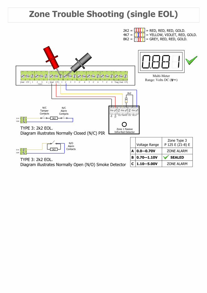
Zone Trouble Shooting (single EOL)
2K2 = = RED, RED, RED, GOLD. 4K7 = = YELLOW, VIOLET, RED, GOLD. 8K2 = = GREY, RED, RED, GOLD.
Gnd 12V 1 C 2 3 C 4 5 C 6 7 C 8 Tmp Gnd 12V Outputs
Gnd 12V 1 2 3 4
Zone 1 Passive Infra-Red Detector
0v
12v EOL TAMPER EOL RELAY
2k2
TYPE 3: 2k2 EOL. Diagram illustrates Normally Closed (N/C) PIR
N/C Alarm
Contacts
2K2 Z1-8
COM
N/C Tamper Contacts
TYPE 3: 2k2 EOL. Diagram illustrates Normally Open (N/O) Smoke Detector
N/O Alarm
Contacts 2K2 Z1-8
COM
Voltage Range
Zone Type 3 P 125 E (Z1-8) E
0.0—0.70V ZONE ALARM
0.70—1.10V SEALED
1.10—5.00V ZONE ALARM
A
B
C
Multi-Meter Range: Volts DC ( )
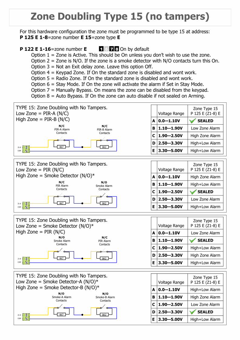
Zone Doubling Type 15 (no tampers)
Voltage Range
Zone Type 15 P 125 E (Z1-8) E
0.0—1.10V SEALED
1.10—1.90V Low Zone Alarm
1.90—2.50V High Zone Alarm
A
B
C
E 3.30—5.00V High+Low Alarm
D 2.50—3.30V High+Low Alarm
N/C PIR-A Alarm
Contacts
4K7 Z1-8
COM
N/C PIR-B Alarm
Contacts
8K2
TYPE 15: Zone Doubling with No Tampers. Low Zone = PIR-A (N/C) High Zone = PIR-B (N/C)
N/C PIR Alarm Contacts
4K7 Z1-8
COM
N/O Smoke Alarm
Contacts
8K2
Voltage Range
Zone Type 15 P 125 E (Z1-8) E
0.0—1.10V High Zone Alarm
1.10—1.90V High+Low Alarm
1.90—2.50V SEALED
A
B
C
E 3.30—5.00V High+Low Alarm
D 2.50—3.30V Low Zone Alarm
TYPE 15: Zone Doubling with No Tampers. Low Zone = PIR (N/C) High Zone = Smoke Detector (N/O)*
Voltage Range
Zone Type 15 P 125 E (Z1-8) E
0.0—1.10V Low Zone Alarm
1.10—1.90V SEALED
1.90—2.50V High+Low Alarm
A
B
C
E 3.30—5.00V High+Low Alarm
D 2.50—3.30V High Zone Alarm
N/O Smoke Alarm
Contacts
4K7 Z1-8
COM
N/C PIR Alarm Contacts
8K2
TYPE 15: Zone Doubling with No Tampers. Low Zone = Smoke Detector (N/O)* High Zone = PIR (N/C)
Voltage Range
Zone Type 15 P 125 E (Z1-8) E
0.0—1.10V High+Low Alarm
1.10—1.90V High Zone Alarm
1.90—2.50V Low Zone Alarm
A
B
C
E 3.30—5.00V High+Low Alarm
D 2.50—3.30V SEALED
N/O Smoke-A Alarm
Contacts
4K7 Z1-8
COM
N/O Smoke-B Alarm
Contacts
8K2
TYPE 15: Zone Doubling with No Tampers. Low Zone = Smoke Detector-A (N/O)* High Zone = Smoke Detector-B (N/O)*
For this hardware configuration the zone must be programmed to be type 15 at address: P 125 E 1-8=zone number E 15=zone type E P 122 E 1-16=zone number E On by default Option 1 = Zone is Active. This should be On unless you don’t wish to use the zone. Option 2 = Zone is N/O. If the zone is a smoke detector with N/O contacts turn this On. Option 3 = Not an Exit delay zone. Leave this option Off. Option 4 = Keypad Zone. If On the standard zone is disabled and wont work. Option 5 = Radio Zone. If On the standard zone is disabled and wont work. Option 6 = Stay Mode. If On the zone will activate the alarm if Set in Stay Mode. Option 7 = Manually Bypass. On means the zone can be disabled from the keypad. Option 8 = Auto Bypass. If On the zone can auto disable if not sealed on Arming.
1 6 7 8
Voltage Range
Zone Type 14 P 125 E (Z1-8) E
0.0—0.70V Low Zone Tamper
0.70—1.40V SEALED
1.40—2.30V Low Zone Alarm
A
B
C
E 2.80—3.30V High+Low Alarm
D 2.30—2.80V High Zone Alarm
F 3.30—5.0V High Zone Tamper
Alarm Contacts N/C
4K7 Z1-8
COM
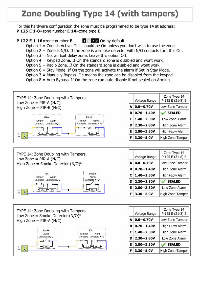
TYPE 14: Zone Doubling with Tampers. Low Zone = PIR-A (N/C) High Zone = PIR-B (N/C)
2K2
PIR-A Tamper Contacts
Alarm Contacts N/C
8K2
PIR-B Tamper Contacts
Zone Doubling Type 14 (with tampers)
Voltage Range
Zone Type 14 P 125 E (Z1-8) E
0.0—0.70V Low Zone Tamper
0.70—1.40V High Zone Alarm
1.40—2.30V High+Low Alarm
A
B
C
E 2.80—3.30V Low Zone Alarm
D 2.30—2.80V SEALED
F 3.30—5.0V High Zone Tamper
Alarm Contacts N/C
4K7 Z1-8
COM
TYPE 14: Zone Doubling with Tampers. Low Zone = PIR-A (N/C) High Zone = Smoke Detector (N/O)*
2K2
PIR Tamper Contacts
Alarm Contacts N/O
8K2
Smoke
Voltage Range
Zone Type 14 P 125 E (Z1-8) E
0.0—0.70V Low Zone Tamper
0.70—1.40V High+Low Alarm
1.40—2.30V High Zone Alarm
A
B
C
E 2.80—3.30V SEALED
D 2.30—2.80V Low Zone Alarm
F 3.30—5.0V High Zone Tamper
Alarm Contacts N/C
8K2 Z1-8
COM
TYPE 14: Zone Doubling with Tampers. Low Zone = Smoke Detector (N/O)* High Zone = PIR-A (N/C)
2K2
PIR Tamper Contacts
Alarm Contacts N/O
4K7
Smoke
For this hardware configuration the zone must be programmed to be type 14 at address: P 125 E 1-8=zone number E 14=zone type E P 122 E 1-16=zone number E On by default Option 1 = Zone is Active. This should be On unless you don’t wish to use the zone. Option 2 = Zone is N/O. If the zone is a smoke detector with N/O contacts turn this On. Option 3 = Not an Exit delay zone. Leave this option Off. Option 4 = Keypad Zone. If On the standard zone is disabled and wont work. Option 5 = Radio Zone. If On the standard zone is disabled and wont work. Option 6 = Stay Mode. If On the zone will activate the alarm if Set in Stay Mode. Option 7 = Manually Bypass. On means the zone can be disabled from the keypad. Option 8 = Auto Bypass. If On the zone can auto disable if not sealed on Arming.
1 6 7 8
Gnd 12V 1 C 2 3 C 4 Outputs
Gnd 12V 1 2 3 4
Zone 1 Passive Infra-Red Detector
0v
12v EOL TAMPER EOL RELAY
2k2
Zone 5 Passive Infra-Red Detector
0v
12v EOL TAMPER EOL RELAY
PIR 2 = Zone 5
PIR 1 = Zone 1
4k7
8k2
Link
Gnd 12V 1 C 2 3 C 4 Outputs
Gnd 12V 1 2 3 4
Zone 1 Passive Infra-Red Detector
0v
12v EOL TAMPER EOL RELAY
Zone 5 Passive Infra-Red Detector
0v
12v EOL TAMPER EOL RELAY
To Zone 5 Zone 1& 5
4k7
8k2
Link 2k2
Alarm Contacts N/C
4K7 Z1-8
COM 2K2
PIR-A Tamper Contacts
Alarm Contacts N/C
8K2
PIR-B Tamper Contacts
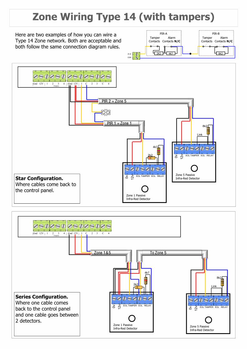
Zone Wiring Type 14 (with tampers)
Here are two examples of how you can wire a Type 14 Zone network. Both are acceptable and both follow the same connection diagram rules.
Star Configuration. Where cables come back to the control panel.
Series Configuration. Where one cable comes back to the control panel and one cable goes between 2 detectors.
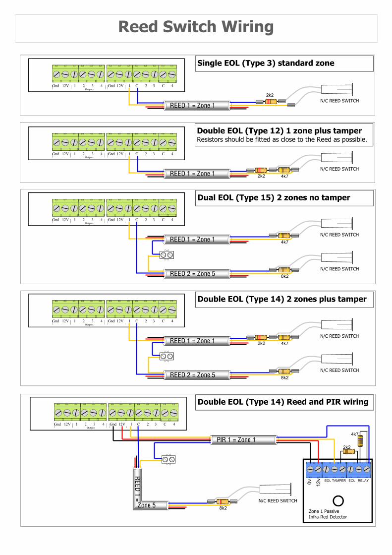
Single EOL (Type 3) standard zone
Reed Switch Wiring
N/C REED SWITCH
Gnd 12V 1 C 2 3 C 4 Outputs
Gnd 12V 1 2 3 4
2k2
REED 1 = Zone 1
N/C REED SWITCH
Gnd 12V 1 C 2 3 C 4 Outputs
Gnd 12V 1 2 3 4
2k2 REED 1 = Zone 1 4k7
N/C REED SWITCH
Outputs Gnd 12V 1 2 3 4
2k2 REED 1 = Zone 1 4k7
N/C REED SWITCH REED 2 = Zone 5 8k2
Gnd 12V 1 C 2 3 C 4
N/C REED SWITCH
Outputs Gnd 12V 1 2 3 4
REED 1 = Zone 1 4k7
N/C REED SWITCH REED 2 = Zone 5 8k2
Gnd 12V 1 C 2 3 C 4
Outputs Gnd 12V 1 2 3 4
N/C REED SWITCH
8k2 Zone 1 Passive Infra-Red Detector
0v
12v EOL TAMPER EOL RELAY
2k2 PIR 1 = Zone 1
4k7
Zone 5
REED 1 =
Gnd 12V 1 C 2 3 C 4
Double EOL (Type 12) 1 zone plus tamper Resistors should be fitted as close to the Reed as possible.
Dual EOL (Type 15) 2 zones no tamper
Double EOL (Type 14) 2 zones plus tamper
Double EOL (Type 14) Reed and PIR wiring
1 2 4
3
Gnd 12V 1 C 2 3 C 4 Outputs
Gnd 12V 1 2 3 4
2k2
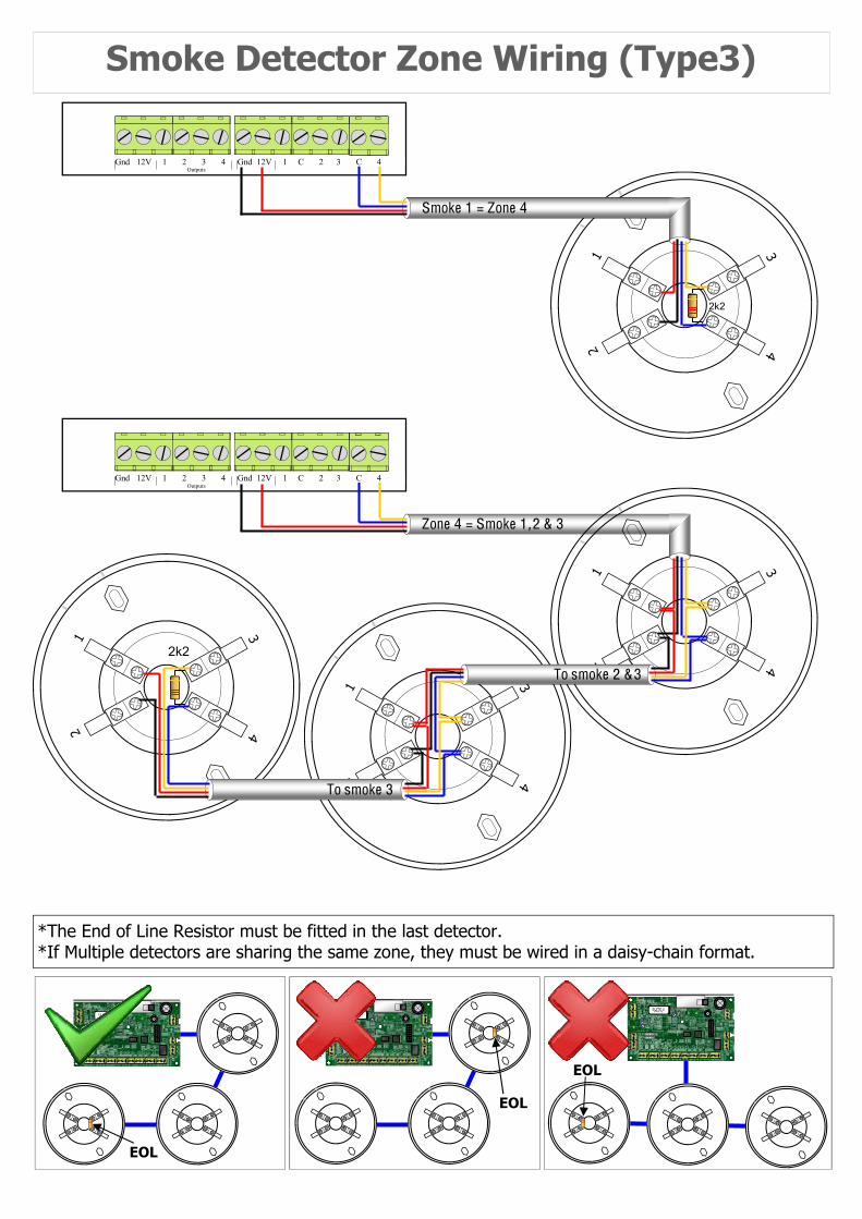
Smoke 1 = Zone 4
*The End of Line Resistor must be fitted in the last detector. *If Multiple detectors are sharing the same zone, they must be wired in a daisy-chain format.
Smoke Detector Zone Wiring (Type3)
Gnd 12V 1 C 2 3 C 4 Outputs
Gnd 12V 1 2 3 4
2k2
1 2 4
3
1 2 4
3
1 2 4
3
Zone 4 = Smoke 1 , 2 & 3
To smoke 2 & 3
To smoke 3
EOL
EOL
EOL
Lin Dat Clk Neg Pos
Lin Dat Clk Neg Pos
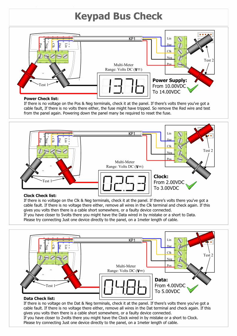
Keypad Bus Check
Lin Dat Clk Neg Pos Multi-Meter
Range: Volts DC ( )
KP1
Lin D
at C
lk N
eg Pos
Power Supply: From 10.00VDC To 14.00VDC
Power Check list: If there is no voltage on the Pos & Neg terminals, check it at the panel. If there’s volts there you've got a cable fault, If there is no volts there either, the fuse might have tripped. So remove the Red wire and test from the panel again. Powering down the panel many be required to reset the fuse.
KP1
Lin D
at C
lk N
eg Pos
Multi-Meter Range: Volts DC ( )
Clock: From 2.00VDC To 3.00VDC
Clock Check list: If there is no voltage on the Clk & Neg terminals, check it at the panel. If there’s volts there you've got a cable fault. If there is no voltage there either, remove all wires in the Clk terminal and check again. If this gives you volts then there is a cable short somewhere, or a faulty device connected. If you have closer to 5volts there you might have the Data wired in by mistake or a short to Data. Please try connecting Just one device directly to the panel, on a 1meter length of cable.
KP1
Lin D
at C
lk N
eg Pos
Multi-Meter Range: Volts DC ( )
Data Check list: If there is no voltage on the Dat & Neg terminals, check it at the panel. If there’s volts there you've got a cable fault. If there is no voltage there either, remove all wires in the Dat terminal and check again. If this gives you volts then there is a cable short somewhere, or a faulty device connected. If you have closer to 2volts there you might have the Clock wired in by mistake or a short to Clock. Please try connecting Just one device directly to the panel, on a 1meter length of cable.
Data: From 4.00VDC To 5.00VDC
Test 1
Test 2
Test 1
Test 1
Test 2
Test 2
ON
1
ANT
RX-16 MF349 v090618
(303, 433 & 915MHz)
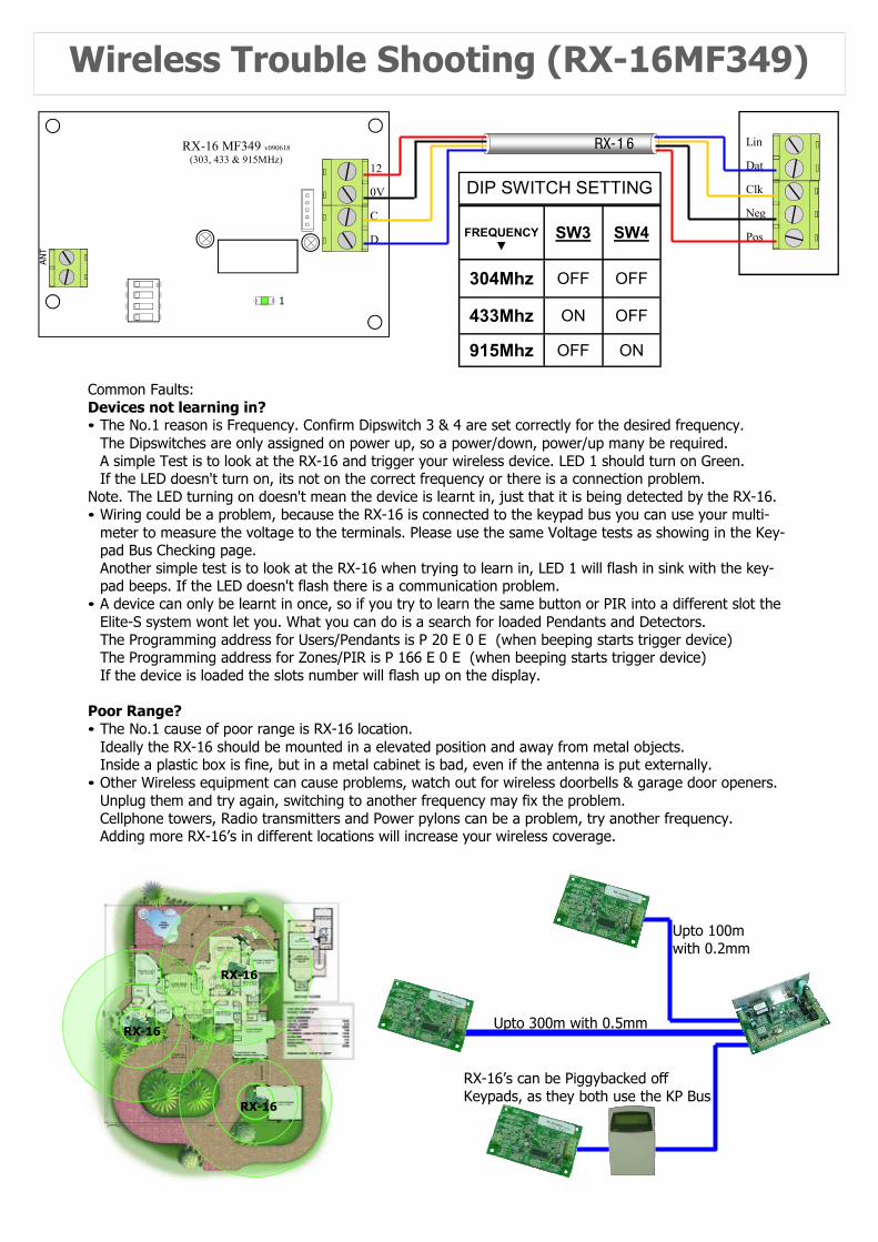
Wireless Trouble Shooting (RX-16MF349)
Lin Dat Clk Neg Pos
RX-1 6
12 0V C D
Common Faults: Devices not learning in? • The No.1 reason is Frequency. Confirm Dipswitch 3 & 4 are set correctly for the desired frequency. The Dipswitches are only assigned on power up, so a power/down, power/up many be required. A simple Test is to look at the RX-16 and trigger your wireless device. LED 1 should turn on Green. If the LED doesn't turn on, its not on the correct frequency or there is a connection problem. Note. The LED turning on doesn't mean the device is learnt in, just that it is being detected by the RX-16. • Wiring could be a problem, because the RX-16 is connected to the keypad bus you can use your multi-
meter to measure the voltage to the terminals. Please use the same Voltage tests as showing in the Key-pad Bus Checking page.
Another simple test is to look at the RX-16 when trying to learn in, LED 1 will flash in sink with the key-pad beeps. If the LED doesn't flash there is a communication problem.
• A device can only be learnt in once, so if you try to learn the same button or PIR into a different slot the Elite-S system wont let you. What you can do is a search for loaded Pendants and Detectors.
The Programming address for Users/Pendants is P 20 E 0 E (when beeping starts trigger device) The Programming address for Zones/PIR is P 166 E 0 E (when beeping starts trigger device) If the device is loaded the slots number will flash up on the display. Poor Range? • The No.1 cause of poor range is RX-16 location. Ideally the RX-16 should be mounted in a elevated position and away from metal objects. Inside a plastic box is fine, but in a metal cabinet is bad, even if the antenna is put externally. • Other Wireless equipment can cause problems, watch out for wireless doorbells & garage door openers. Unplug them and try again, switching to another frequency may fix the problem. Cellphone towers, Radio transmitters and Power pylons can be a problem, try another frequency. Adding more RX-16’s in different locations will increase your wireless coverage.
RX-16
RX-16
RX-16
Upto 300m with 0.5mm
Upto 100m with 0.2mm
RX-16’s can be Piggybacked off Keypads, as they both use the KP Bus
FREQUENCY
▼ SW3 SW4
304Mhz OFF OFF
433Mhz ON OFF
915Mhz OFF ON
DIP SWITCH SETTING