Embed Size (px)
Citation preview

©2021 Advanced Energy Industries, Inc.
ARTESYNLPS200-M SERIES 250 Watts (forced air)150 Watts (convection)
SPECIAL FEATURES
Medical and ITE safeties
Active power factor correction
3” x 5” footprint
Less than 1U high
EN61000-3-2 compliant
Remote sense
Power fail
Adjustable main output
Built-in Class B EMI filter
Overvoltage protection
Overload protection
Thermal overload protection
Isolated 12 V Fan output
LPX200 enclosure kit available
SAFETY
TUV 62368,60601-1
UL 62368,60601-1
cULus 62368,60601-1
CB Certificate & report
CE Mark (LVD)
TYPICAL APPLICATIONS
ITE
Medical
PRODUCT DESCRIPTION
Advanced Energy’s Artesyn LPS200-M series power supplies are compact open-frame designs; measuring just 3 x 5 in, with a height of only 1.5 in, they have a typical full load efficiency of 88 % and a power density in excess of 11 watts per cubic inch. The supplies are primarily intended for use in information technology equipment (ITE) and light industrial systems, as well as for equipment intended for non-patient contact and non-patient critical use in low power medical, dental and laboratory applications.
The power supplies have a full load ambient operating temperature range of 0 to +50 degree Celsius without de-rating and can cold-start from temperatures as low as -20 degrees Celsius. Between 50 and 70 degrees Celsius, the output should be derated by 2.5 percent per degree.
AT A GLANCE
Total Power
150 to 250 Watts
Input Voltage
90 to 264 Vac
# of Outputs
Single

LPS200-M Series
2advancedenergy.com Rev. 12.10.20_#1.8
OptionsOptionsOptionsOptions
None
MODEL NUMBERS
Model NumberOutput Voltage
Minimum Load
Maximum Load with Convection Cooling
Maximum Load with 30CFM
Forced Air
Peak Load1Regulation2
Ripple P/P3
LPS202-M 5V 0A 20A 40A 44A ±2% 50mV
LPS203-M 12V 0A 10.3A 20.8A 22A ±2% 120mV
LPS204-M 15V 0A 8.3A 16.6A 18A ±2% 150mV
LPS205-M 24V 0A 5.2A 10.4A 11.5A ±2% 240mV
LPS208-M 48V 0A 2.6A 5.2A 5.8A ±2% 480mV
Note 1 - Peak current lasting<30seconds with a maximum 10% duty cycle.Note 2 - At 25OC including initial tolerance, line voltage, load currents and output voltages adjusted to factory settings.Note 3 - Peak-to-peak with 20MHz bandwidth and 10uF (tantalum capacitor) in parallel with a 0.1uF capacitor at rated line voltage and load ranges.

LPS200-M Series
3advancedenergy.com Rev. 12.10.20_#1.8
Absolute Maximum Ratings
Stress in excess of those listed in the “Absolute Maximum Ratings” may cause permanent damage to the power supply. These are stress ratings only and functional operation of the unit is not implied at these or any other conditions above those given in the operational sections of this TRN. Exposure to any absolute maximum rated condition for extended periods may adversely affect the power supply’s reliability.
ELECTRICAL SPECIFICATIONS
Table 1. Absolute Maximum Ratings
Parameter Model Symbol Min Typ Max Unit
Input VoltageAC continuous operationDC continuous operation
All modelsAll models
VIN,AC
VIN,DC
90120
--
264300
VacVdc
Maximum Output Power (Main+Fan)Convection continuous operation
LPS202-MLPS203-MLPS204-MLPS205-MLPS208-M
PO,maxCC
-----
-----
100125125125125
W
Maximum Output Power (Main+Fan)Force air continuous operation-30CFM
LPS202-MLPS203-MLPS204-MLPS205-MLPS208-M
PO,maxFA
-----
-----
200250250250250
W
Isolation VoltageInput to outputs
Input to safety groundOutput to output IsolationOutputs to safety ground
All modelsAll modelsAll modelsAll models
----
----
40001500100500
VacVacVdcVac
Ambient Operating Temperature All models TA 0 - +701 OC
Cold Start-up Temperature All models TST -20 - - OC
Storage Temperature All models TSTG -40 - +85 OC
Humidity (non-condensing)Operating
Non-operatingAll modelsAll models
1010
--
9095
%%
AltitudeOperating
Non-operatingAll modelsAll models
-500-1000
--
13,0002
50,000feetfeet
Note 1 - Derate each output at 2.5% per degree C from 50ºC to 70ºC.Note 2 - Derate maximum operating temperature by 1ºC per 1,000 feet above 13,000 feet.

LPS200-M Series
4advancedenergy.com Rev. 12.10.20_#1.8
Input Specifications
ELECTRICAL SPECIFICATIONS
Table 2. Input Specifications
Parameter Condition Symbol Min Typ Max Unit
Operating Input Voltage, AC All VIN,AC 90 - 264 Vac
Input AC Source Frequency All fIN,AC 47 - 63 Hz
Operating Input Voltage, DC All VIN,DC 120 300 VDC
Maximum Input Current(IO = IO,max,)
VIN,AC = 90VacVIN,AC = 264Vac
IIN,max - -3.51.5
ARMS
No Load Input Power All PIN - - 10 W
No Load Input CurrentVINAC = 90Vac
VIN,AC = 264VacIIN,no_load - -
250150
mARMS
Harmonic Line Currents All THD Per EN61000-3-2
Power Factor All - 0.99 -
Startup Surge Current (Inrush)@ 25°C
VIN,AC = 230Vac Cold start - - 50 APK
Input AC Low Line Start-up Voltage IO = 0 VIN,AC-start 84 - 89 Vac
Input AC Under Voltage Lockout Voltage IO = 0 VIN,AC-stop 70 - 80 Vac
Input DC Low Line Start-up Voltage IO = 0 VIN,AC-start 110 - 119 Vdc
Input DC Under Voltage Lockout Voltage IO = 0 VIN,AC-stop 102 - 109 Vdc
PFC Switching Frequency VIN,AC = 180Vac fSW,PFC 30 - 68 KHz
DCDC Switching Frequency All fSW,DC-DC 260 - 300 KHz
Operating Efficiency @ 25oCIO = IO,max
VIN,AC = 100Vacη - 86 - %
Hold Up Time VIN,AC=115Vac tHold-Up 16 - - mSec
Turn On Delay VIN,AC=90Vac tTurn-on - - 2 Sec
Leakage Current to safety ground VIN=264Vac,fIN=50/60Hz IIN,leakage - - 275 uA
System Stability:Phase Margin
Gain Margin330uF/A
Capacitive Load4510
--
--
ØdB

LPS200-M Series
5advancedenergy.com Rev. 12.10.20_#1.8
Output Specifications
ELECTRICAL SPECIFICATIONS
Table 3. Output Specifications
Parameter Condition Symbol Min Typ Max Unit
Output Regulation
LPS202-M LPS203-M LPS204-M LPS205-M LPS208-M
VO=90~264VacVO
4.9011.7614.7023.52 47.04
5.0012.0015.0024.0048.00
5.1012.2415.3024.4848.96
V
All models VFAN 11.4 12.0 12.6
Output Ripple, pk-pk
LPS202-M LPS203-M LPS204-M LPS205-M LPS208-M
Measure with a 0.1μF ceramic capacitor in parallel with a 10μF
tantalum capacitor, 0 to 20MHz bandwidth
VO
-----
-----
50.0120.0150.0240.0 480.0
mVPK-PK
All models VFAN - - 120.0
Output Current
LPS202-M LPS203-M LPS204-M LPS205-MLPS208-M
Convection CoolingIO
00000
-----
20.010.38.35.22.6
A
All models IFAN 0 - 0.5
Output Current
LPS202-M LPS203-M LPS204-M LPS205-M LPS208-M
30CFM Force AirIO
00000
-----
40.020.816.610.45.2
A
All models IFAN 0 - 1.0
Output Power
LPS202-M LPS203-M LPS204-M LPS205-M LPS208-M
VO=90~264Vac/127~300Vdc
Natural convection coolingPo
-----
100125125125125
-----
W
Output Power
LPS202-M LPS203-M LPS204-M LPS205-M LPS208-M
Vo=90~264Vac/127~300Vdc
Lengthwise/Sideways Forced air cooling of
30CFM
Po
-----
200250250250250
-----
W
VO Load CapacitanceStart up
Using CR load and capacitive load in parallel
- 0 - 330 mF/A
VO Dynamic Response - Peak Deviation
50% load change (From 50% to 100%)
Slew rate = 1A/us100uF/A
±%VO - - 3 %
VO Dynamic Response - Setting Time
50% load change (From 50% to 100%)
Slew rate = 1A/us100uF/A
Ts - - 500 uSec

LPS200-M Series
6advancedenergy.com Rev. 12.10.20_#1.8
Output Specifications
ELECTRICAL SPECIFICATIONS
Table 3. Output Specifications Con’t
Parameter Condition Symbol Min Typ Max Unit
Output Adjust Range
LPS202-M LPS203-MLPS204-MLPS205-MLPS208-M
VIN,AC = 115VacIO = 50% of IO,maxFA
IFAN = 0VO
4.510.813.521.643.2
-----
5.513.216.526.452.8
V
VO Turn On Overshoot
LPS202-MLPS203-MLPS204-MLPS205-MLPS208-M
IO = 0, IFAN = 0 VO
-----
-----
5.1512.3615.4524.7249.44
V
VO Long Term StabilityIo=Full load, VO=100Vac,
Max change over 24 hours after thermal equilibrium
±%VO - - 1.0 %
VO Over Voltage Protection Latch off
(AC recycle to reset)%VO 130 - 150 %
VO Over Current Protection All %IO 110 - 160 %
Over Temperature Protection All Auto Recovery
Short Circuit Protection All Auto Recovery
Remote Sense, + and -Maximum compensation
at each output lineVSENSE - - 400 mV

LPS200-M Series
7advancedenergy.com Rev. 12.10.20_#1.8
LPS202-M Performance Curves
ELECTRICAL SPECIFICATIONS
Figure 1: LPS202-M Turn-on delay
Vin = 90Vac Load: Io = 40A, IFAN = 0A
Ch 1: VIN Ch 2: Vo Ch 3: Power Fail
Figure 2: LPS202-M Hold-up Time
Vin = 90Vac Load: Io = 40A, IFAN = 0A
Ch 1: VIN Ch 2: Vo Ch 3: Power Fail
Figure 4: LPS202-M Input Current Waveform
Vin = 115Vac Load: Io = 40A, IFAN = 0A
Ch 1: IIN
Figure 5: LPS202-M Output Voltage Startup Characteristic
Vin = 90Vac Load: Io = 40A, IFAN = 0A
Ch 1: Vo Ch 2: Power Fail Output Capacitance = 330uF/A
Figure 6: LPS202-M Ripple and Noise Measurement
Vin = 115Vac Load: Io = 40A, IFAN = 0A
Ch 1: Vo
Figure 3: LPS202-M Inrush Current
Vin = 230Vac Load: Io = 0A, IFAN = 0A, Turn on at 90 deg
Ch 1: VIN Ch 2: IIN

LPS200-M Series
8advancedenergy.com Rev. 12.10.20_#1.8
LPS202-M Performance Curves
ELECTRICAL SPECIFICATIONS
Figure 7: LPS202-M Transient Response – Vo Deviation
Vin = 115Vac Load: Io = 100% to 50%, 1A/us slew rate
Ch 1: Vo Ch 2: Io
Figure 8: LPS202-M Transient Response – Vo Deviation
Vin = 115Vac Load: Io = 50% to 100%, 1A/us slew rate
Ch 1: Vo Ch 2: Io
Figure 10: LPS202-M Efficiency Curves @ 25 degC
30 CFM Forced Air
Vin = 90 to 264Vac Load: Io = 0 to 40A, IFAN = 0A
Figure 11: LPS202-M Derating Curves
Vin = 115Vac Load: Io = 0 to 40A, IFAN = 0A
Figure 9: LPS202-M Efficiency Curves @ 25 degC
Convection Cooling
Vin = 90 to 264Vac Load: Io = 0 to 20A, IFAN = 0A
Ou
tpu
t C
urr
en
t (A
)E
ffic
ien
cy
(%
)
Eff
icie
ncy
(%
)LPS2 0 2 - M Ef f iciency ( %)
70
75
80
85
90
95
0 5 10 15 20 25 30 35 40
Output Current (A)
90V ac 115V ac 230Vac 264V ac
LPS2 0 2 -M Thermal A irf low D erat ing
0
5
10
15
20
25
30
35
40
45
0 10 20 30 40 50 60 70
Ambient Temperature (oC)
0 LFM 200LFM
LPS2 0 2 - M Ef f iciency ( %)
55
60
65
70
75
80
85
90
95
0 2 4 6 8 10 12 14 16 18 20
Output Current (A)
90V ac 115V ac 230Vac 264V ac

LPS200-M Series
9advancedenergy.com Rev. 12.10.20_#1.8
LPS203-M Performance Curves
ELECTRICAL SPECIFICATIONS
Figure 12: LPS203-M Turn-on delay
Vin = 90Vac Load: Io = 20.8A, IFAN = 0A
Ch 1: VIN Ch 2: Vo Ch 3: Power Fail
Figure 13: LPS203-M Hold-up Time
Vin = 90Vac Load: Io = 20.8A, IFAN = 0A
Ch 1: VIN Ch 2: Vo Ch 3: Power Fail
Figure 15: LPS203-M Input Current Waveform
Vin = 115Vac Load: Io = 20.8A, IFAN = 0A
Ch 1: IIN
Figure 16: LPS203-M Output Voltage Startup Characteristic
Vin = 90Vac Load: Io = 20.8A, IFAN = 0A
Ch 1: Vo Ch 2: Power Fail Output Capacitance = 330uF/A
Figure 17: LPS203-M Ripple and Noise Measurement
Vin = 115Vac Load: Io = 20.8A, IFAN = 0A
Ch 1: Vo
Figure 14: LPS203-M Inrush Current
Vin = 230Vac Load: Io = 0A, IFAN = 0A, Turn on at 90 deg
Ch 1: VIN Ch 2: IIN

LPS200-M Series
10advancedenergy.com Rev. 12.10.20_#1.8
LPS203-M Performance Curves
ELECTRICAL SPECIFICATIONS
Figure 18: LPS203-M Transient Response – Vo Deviation
Vin = 115Vac Load: Io = 100% to 50%, 1A/us slew rate
Ch 1: Vo Ch 2: Io
Figure 19: LPS203-M Transient Response – Vo Deviation
Vin = 115Vac Load: Io = 50% to 100%, 1A/us slew rate
Ch 1: Vo Ch 2: Io
Figure 21: LPS203-M Efficiency Curves @ 25 degC
30 CFM Forced Air
Vin = 90 to 264Vac Load: Io = 0 to 20.8A, IFAN = 0A
Figure 22: LPS203-M Derating Curves
Vin = 115Vac Load: Io = 0 to 20.8A, IFAN = 0A
Figure 20: LPS203-M Efficiency Curves @ 25 degC
Convection Cooling
Vin = 90 to 264Vac Load: Io = 0 to 10.4A, IFAN = 0A
Ou
tpu
t C
urr
en
t (A
)E
ffic
ien
cy
(%
)
Eff
icie
ncy
(%
)LPS2 0 3 - M Ef f iciency ( %)
60
65
70
75
80
85
90
95
0 1 2 3 4 5 6 7 8 9 10
Output Current (A)
90V ac 115V ac 230V ac 264Vac
LPS2 0 3 - M Ef f iciency ( %)
70
75
80
85
90
95
0 2 4 6 8 10 12 14 16 18 20
Output Current (A)
90V ac 115V ac 230V ac 264Vac
LPS2 0 3 -M Thermal A irf low D erat ing
0
5
10
15
20
25
0 10 20 30 40 50 60 70
Ambient Temperature (oC)
0 LFM 200 LFM

LPS200-M Series
11advancedenergy.com Rev. 12.10.20_#1.8
LPS204-M Performance Curves
ELECTRICAL SPECIFICATIONS
Figure 23: LPS204-M Turn-on delay
Vin = 90Vac Load: Io = 16.6A, IFAN = 0A
Ch 1: VIN Ch 2: Vo Ch 3: Power Fail
Figure 24: LPS204-M Hold-up Time
Vin = 90Vac Load: Io = 16.6A, IFAN = 0A
Ch 1: VIN Ch 2: Vo Ch 3: Power Fail
Figure 26: LPS204-M Input Current Waveform
Vin = 115Vac Load: Io = 16.6A, IFAN = 0A
Ch 1: IIN
Figure 27: LPS204-M Output Voltage Startup Characteristic
Vin = 90Vac Load: Io = 16.6A, IFAN = 0A
Ch 1: Vo Ch 2: Power Fail Output Capacitance = 330uF/A
Figure 28: LPS204-M Ripple and Noise Measurement
Vin = 115Vac Load: Io = 16.6A, IFAN = 0A
Ch 1: Vo
Figure 25: LPS204-M Inrush Current
Vin = 230Vac Load: Io = 0A, IFAN = 0A, Turn on at 90 deg
Ch 1: VIN Ch 2: IIN

LPS200-M Series
12advancedenergy.com Rev. 12.10.20_#1.8
LPS204-M Performance Curves
ELECTRICAL SPECIFICATIONS
Figure 29: LPS204-M Transient Response – Vo Deviation
Vin = 115Vac Load: Io = 100% to 50%, 1A/us slew rate
Ch 1: Vo Ch 2: Io
Figure 30: LPS204-M Transient Response – Vo Deviation
Vin = 115Vac Load: Io = 50% to 100%, 1A/us slew rate
Ch 1: Vo Ch 2: Io
Figure 32: LPS204-M Efficiency Curves @ 25 degC
30 CFM Forced Air
Vin = 90 to 264Vac Load: Io = 0 to 16.6A, IFAN = 0A
Figure 33: LPS204-M Derating Curves
Vin = 115Vac Load: Io = 0 to 16.6A, IFAN = 0A
Figure 31: LPS204-M Efficiency Curves @ 25 degC
Convection Cooling
Vin = 90 to 264Vac Load: Io = 0 to 8.3A, IFAN = 0A
Ou
tpu
t C
urr
en
t (A
)E
ffic
ien
cy
(%
)
Eff
icie
ncy
(%
)LPS2 0 4 - M Ef f iciency ( %)
60
65
70
75
80
85
90
95
0 1 2 3 4 5 6 7 8
Output Current (A)
90V ac 115V ac 230Vac 264V ac
LPS2 0 4 - M Ef f iciency ( %)
70
75
80
85
90
95
0 2 4 6 8 10 12 14 16
Output Current (A)
90V ac 115V ac 230V ac 264Vac
LPS2 0 4 -M Thermal A irf low D erat ing
0
2
4
6
8
10
12
14
16
18
0 10 20 30 40 50 60 70
Ambient Temperature (oC)
0 LFM 200 LFM

LPS200-M Series
13advancedenergy.com Rev. 12.10.20_#1.8
LPS205-M Performance Curves
ELECTRICAL SPECIFICATIONS
Figure 34: LPS205-M Turn-on delay
Vin = 90Vac Load: Io = 10.4A, IFAN = 0A
Ch 1: VIN Ch 2: Vo Ch 3: Power Fail
Figure 35: LPS205-M Hold-up Time
Vin = 90Vac Load: Io = 10.4A, IFAN = 0A
Ch 1: VIN Ch 2: Vo Ch 3: Power Fail
Figure 37: LPS205-M Input Current Waveform
Vin = 115Vac Load: Io = 10.4A, IFAN = 0A
Ch 1: IIN
Figure 38: LPS205-M Output Voltage Startup Characteristic
Vin = 90Vac Load: Io = 10.4A, IFAN = 0A
Ch 1: Vo Ch 2: Power Fail Output Capacitance = 330uF/A
Figure 39: LPS205-M Ripple and Noise Measurement
Vin = 115Vac Load: Io = 10.4A, IFAN = 0A
Ch 1: Vo
Figure 36: LPS205-M Inrush Current
Vin = 230Vac Load: Io = 0A, IFAN = 0A, Turn on at 90 deg
Ch 1: VIN Ch 2: IIN

LPS200-M Series
14advancedenergy.com Rev. 12.10.20_#1.8
LPS205-M Performance Curves
ELECTRICAL SPECIFICATIONS
Figure 40: LPS205-M Transient Response – Vo Deviation
Vin = 115Vac Load: Io = 100% to 50%, 1A/us slew rate
Ch 1: Vo Ch 2: Io
Figure 41: LPS205-M Transient Response – Vo Deviation
Vin = 115Vac Load: Io = 50% to 100%, 1A/us slew rate
Ch 1: Vo Ch 2: Io
Figure 43: LPS205-M Efficiency Curves @ 25 degC
30 CFM Forced Air
Vin = 90 to 264Vac Load: Io = 0 to 10.4A, IFAN = 0A
Figure 44: LPS205-M Derating Curves
Vin = 115Vac Load: Io = 0 to 10.4A, IFAN = 0A
Figure 42: LPS205-M Efficiency Curves @ 25 degC
Convection Cooling
Vin = 90 to 264Vac Load: Io = 0 to 5.2A, IFAN = 0A
Ou
tpu
t C
urr
en
t (A
)E
ffic
ien
cy
(%
)
Eff
icie
ncy
(%
)LPS2 0 5- M Ef f iciency ( %)
55
60
65
70
75
80
85
90
95
0 0.5 1 1.5 2 2.5 3 3.5 4 4.5 5
Output Current (A)
90V ac 115V ac 230V ac 264Vac
LPS2 0 5- M Ef f iciency ( %)
65
70
75
80
85
90
95
0 1 2 3 4 5 6 7 8 9 10
Output Current (A)
90V ac 115V ac 230V ac 264Vac
LPS2 0 5-M Thermal A irf low D erat ing
0
2
4
6
8
10
12
0 10 20 30 40 50 60 70
Ambient Temperature (oC)
0 LFM 200 LFM

LPS200-M Series
15advancedenergy.com Rev. 12.10.20_#1.8
LPS208-M Performance Curves
ELECTRICAL SPECIFICATIONS
Figure 45: LPS208-M Turn-on delay
Vin = 90Vac Load: Io = 5.2A, IFAN = 0A
Ch 1: VIN Ch 2: Vo Ch 3: Power Fail
Figure 46: LPS208-M Hold-up Time
Vin = 90Vac Load: Io = 5.2A, IFAN = 0A
Ch 1: VIN Ch 2: Vo Ch 3: Power Fail
Figure 48: LPS208-M Input Current Waveform
Vin = 115Vac Load: Io = 5.2A, IFAN = 0A
Ch 1: IIN
Figure 49: LPS208-M Output Voltage Startup Characteristic
Vin = 90Vac Load: Io = 5.2A, IFAN = 0A
Ch 1: Vo Ch 2: Power Fail Output Capacitance = 330uF/A
Figure 50: LPS208-M Ripple and Noise Measurement
Vin = 115Vac Load: Io = 5.2A, IFAN = 0A
Ch 1: Vo
Figure 47: LPS208-M Inrush Current
Vin = 230Vac Load: Io = 0A, IFAN = 0A, Turn on at 90 deg
Ch 1: VIN Ch 2: IIN

LPS200-M Series
16advancedenergy.com Rev. 12.10.20_#1.8
LPS208-M Performance Curves
ELECTRICAL SPECIFICATIONS
Figure 51: LPS208-M Transient Response – Vo Deviation
Vin = 115Vac Load: Io = 100% to 50%, 1A/us slew rate
Ch 1: Vo Ch 2: Io
Figure 52: LPS208-M Transient Response – Vo Deviation
Vin = 115Vac Load: Io = 50% to 100%, 1A/us slew rate
Ch 1: Vo Ch 2: Io
Figure 54: LPS208-M Efficiency Curves @ 25 degC
30 CFM Forced Air
Vin = 90 to 264Vac Load: Io = 0 to 5.2A, IFAN = 0A
Figure 55: LPS208-M Derating Curves
Vin = 115Vac Load: Io = 0 to 5.2A, IFAN = 0A
Figure 53: LPS208-M Efficiency Curves @ 25 degC
Convection Cooling
Vin = 90 to 264Vac Load: Io = 0 to 2.6A, IFAN = 0A
Ou
tpu
t C
urr
en
t (A
)E
ffic
ien
cy
(%
)
Eff
icie
ncy
(%
)LPS2 0 8 - M Ef f iciency ( %)
60
65
70
75
80
85
90
95
0 0.3 0.6 0.9 1.2 1.5 1.8 2.1 2.4
Output Current (A)
90V ac 115V ac 230V ac 264Vac
LPS2 0 8 - M Ef f iciency ( %)
70
75
80
85
90
95
0 0.5 1 1.5 2 2.5 3 3.5 4 4.5 5
Output Current (A)
90V ac 115V ac 230V ac 264Vac
LPS2 0 8 -M Thermal A irf low D erat ing
0
1
2
3
4
5
6
0 10 20 30 40 50 60 70
Ambient Temperature (oC)
0 LFM 200 LFM

LPS200-M Series
17advancedenergy.com Rev. 12.10.20_#1.8
Protection Function Specifications
Input Fuse
LPS200-M series power supply is equipped with an internal non user serviceable 5A, 250 Vac for fault protection in both the ‘line’ and ‘neutral’ lines input.
Over Voltage Protection (OVP)
The power supply main Vo output will latch off during output overvoltage with the AC line recycled to reset the latch.
LPS202-M
LPS203-M
LPS204-M
LPS205-M
LPS208-M
ELECTRICAL SPECIFICATIONS
Parameter Min Typ Max Unit
VO Output Overvoltage 6.5 / 7.5 V
Parameter Min Typ Max Unit
VO Output Overvoltage 15.6 / 18.0 V
Parameter Min Typ Max Unit
VO Output Overvoltage 19.5 / 22.5 V
Parameter Min Typ Max Unit
VO Output Overvoltage 31.2 / 36.0 V
Parameter Min Typ Max Unit
VO Output Overvoltage 62.4 / 72.0 V
LPS200-M Series
18advancedenergy.com Rev. 12.10.20_#1.8
Protection Function Specifications
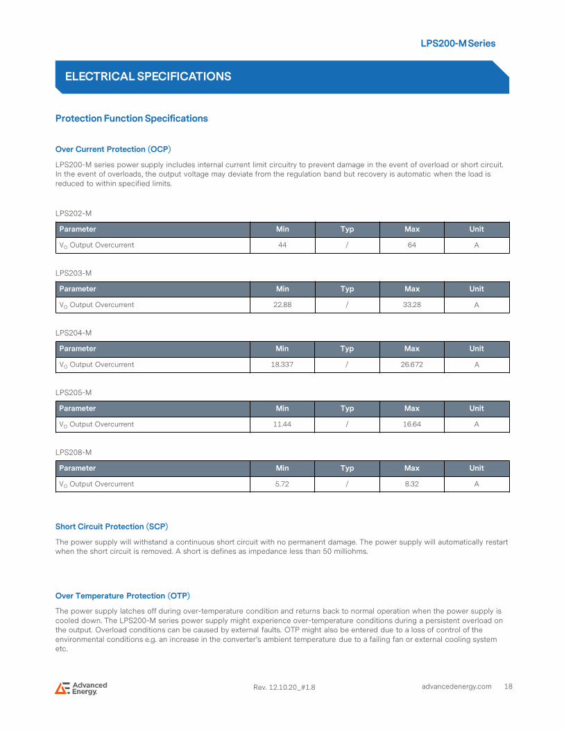
Over Current Protection (OCP)
LPS200-M series power supply includes internal current limit circuitry to prevent damage in the event of overload or short circuit. In the event of overloads, the output voltage may deviate from the regulation band but recovery is automatic when the load isreduced to within specified limits.
LPS202-M
LPS203-M
LPS204-M
LPS205-M
LPS208-M
Short Circuit Protection (SCP)
The power supply will withstand a continuous short circuit with no permanent damage. The power supply will automatically restartwhen the short circuit is removed. A short is defines as impedance less than 50 milliohms.
Over Temperature Protection (OTP)
The power supply latches off during over-temperature condition and returns back to normal operation when the power supply is cooled down. The LPS200-M series power supply might experience over-temperature conditions during a persistent overload on the output. Overload conditions can be caused by external faults. OTP might also be entered due to a loss of control of the environmental conditions e.g. an increase in the converter’s ambient temperature due to a failing fan or external cooling systemetc.
ELECTRICAL SPECIFICATIONS
Parameter Min Typ Max Unit
VO Output Overcurrent 44 / 64 A
Parameter Min Typ Max Unit
VO Output Overcurrent 22.88 / 33.28 A
Parameter Min Typ Max Unit
VO Output Overcurrent 18.337 / 26.672 A
Parameter Min Typ Max Unit
VO Output Overcurrent 11.44 / 16.64 A
Parameter Min Typ Max Unit
VO Output Overcurrent 5.72 / 8.32 A

LPS200-M Series
19advancedenergy.com Rev. 12.10.20_#1.8
Mechanical Outlines (Dimensioning and Mounting Locations)
- All dimensions in inches [mm], tolerance is +/-0.02” [0.5mm]
- Mounting holes M1 and M2 should be grounded for EMI purpose
- Mounting hole M1 is safety ground connection
- Requires mounting on standoffs 0.20” [5.0mm] in height
MECHANICAL SPECIFICATIONS

LPS200-M Series
20advancedenergy.com Rev. 12.10.20_#1.8
Connector Definitions
AC Input Connector – SK1
Pin 1 - Neutral
Pin 3 - Line
Earth Ground - GND
Output Connector – SK2
TB-1 – Common
TB-2 – Main output
Control Signal Header - SK3
Pin 1 – + Remote Sense
Pin 2 – - Remote Sense
Pin 3 – N/C
Pin 4 – N/C
Pin 5 – Power Fail
Pin 6 – Common
Pin 7 – N/C
Pin 8 – Common
Pin 9 – +12V FAN
Pin 10 – + 12V FAN Return (isolated)1
Note 1 - FAN Return is isolated from the main Output Return
Note 2 - Recommended Screw Torque for SK2 terminal (M3.5 X 0.6P) = 6-8 Kgf-cm
MECHANICAL SPECIFICATIONS

LPS200-M Series
21advancedenergy.com Rev. 12.10.20_#1.8
Power / Signal Mating Connectors and Pin Types
LPS200-M connector kit can be ordered separately. Connector Kit #: 70-841-020.
A LPS200-M connector kit contains the following:
- 1pcs Molex 09-50-8031 header housing for SK1
- 4pcs Molex 08-52-0113 crimp pins for Molex 09-50-8031
- 1pcs Molex 01-90020001 insulated female lug for GND
- 2pcs Molex 01-90990044 insulated snap spade terminals for SK2
- 1pcs Molex 90142-0010 header housing for SK5
- 12pcs Molex 90119-2110 crimp pins for Molex 90142-0010
MECHANICAL SPECIFICATIONS
Table 4. Mating Connectors for LPS200-M Series
ReferenceReferenceReferenceReference VendorVendorVendorVendor Mating Connector or EquivalentMating Connector or EquivalentMating Connector or EquivalentMating Connector or EquivalentMating Pins/Terminals or Mating Pins/Terminals or Mating Pins/Terminals or Mating Pins/Terminals or EquivalentEquivalentEquivalentEquivalent
SK1Molex 09-50-8031 08-52-0113
Landwin 3060S0302 3360T011P
GND Molex 01-90020001
SK2 Molex 01-90990044
SK3Molex 90142-0010 90119-2110
AMP 87977-3 87309-8

LPS200-M Series
22advancedenergy.com Rev. 12.10.20_#1.8
Weight
The LPS200-M series weight is 0.75lb / 340g maximum.
MECHANICAL SPECIFICATIONS

LPS200-M Series
23advancedenergy.com Rev. 12.10.20_#1.8
EMC Immunity
LPS200-M series power supply is designed to meet the following EMC immunity specifications.
ENVIRONMENTAL SPECIFICATIONS
Table 5. Environmental SpecificationsTable 5. Environmental SpecificationsTable 5. Environmental SpecificationsTable 5. Environmental Specifications
DocumentDocumentDocumentDocument DescriptionDescriptionDescriptionDescription
FCC Part 15 Subpart J Class B/ EN55032, Level B
Conducted and Radiated EMI Limits
EN61000-3-2 Harmonics
IEC/EN 61000-4-2 Electromagnetic Compatibility (EMC) - Testing and measurement techniques –Electrostatic discharge immunity test. +/-8KV air, +/-4KV contact discharge, performance Criteria B
IEC/EN 61000-4-3 Electromagnetic Compatibility (EMC) - Testing and measurement techniques, Radiated, radio-frequency, electromagnetic field immunity test
IEC/EN 61000-4-4 Electromagnetic Compatibility (EMC) - Testing and measurement techniques, Electrical Fast Transient/Burst Immunity Test. 2KV for AC power port, 1.0KV for DC ports, I/O and signal ports performance Criteria B
IEC/EN 61000-4-5 Electromagnetic Compatibility (EMC) - Testing and measurement techniques – 2KV common mode and 1KV differential mode for AC ports and 0.5kV differential mode for DC power, I/O and signal ports, performance criteria B.
IEC/EN 61000-4-6 Electromagnetic Compatibility (EMC) - Testing and measurement techniques - Radio frequency common mode, Levels 3V (rms) Modulated AM 80%.
IEC/EN 61000-4-8 Electromagnetic Compatibility (EMC) - Testing and measurement techniques : Power Frequency Magnetic Immunity, 1 A/m.

LPS200-M Series
24advancedenergy.com Rev. 12.10.20_#1.8
Safety Certifications
The LPS200-M series power supply is intended for inclusion in other equipment and the installer must ensure that it is in compliance with all the requirements of the end application. This product is only for inclusion by professional installers within other equipment and must not be operated as a stand alone product.
ENVIRONMENTAL SPECIFICATIONS
Table 6. Safety Certifications for LPS200-M Series Power Supply System
StandardStandardStandardStandard DescriptionDescriptionDescriptionDescription
UL 62368-1 US and Canada Requirements
CSA 22.2 No. 62368-1Information Technology Equipment - Safety - Part 1:General Requirements (Bi-National standard, with UL 60950-1)
EN62368-1 European Requirements
CB Certificate and Report (All CENELEC Countries)

LPS200-M Series
25advancedenergy.com Rev. 12.10.20_#1.8
ENVIRONMENTAL SPECIFICATIONS
EMI Emissions
The LPS200-M series has been designed to comply with the Class B limits of EMI requirements of EN55032 (FCC Part 15) and CISPR 22 (EN55032) for emissions and relevant sections of EN61000 (IEC 61000) for immunity.
The unit is enclosed inside a metal box, tested at 150W using resistive load with cooling fan.
Conducted Emissions
The applicable standard for conducted emissions is EN55032 (FCC Part 15). Conducted noise can appear as both differential mode and common mode noise currents. Differential mode noise is measured between the two input lines, with the major components occurring at the supply fundamental switching frequency and its harmonics. Common mode noise, a contributor to both radiated emissions and input conducted emissions, is measured between the input lines and system ground and can be broadband in nature.
Conducted EMI emissions specifications of the LPS200-M series:
Radiated Emissions
Unlike conducted EMI, radiated EMI performance in a system environment may differ drastically from that in a stand-alone power supply. The shielding effect provided by the system enclosure may bring the EMI level from Class A to Class B. It is thus recommended that radiated EMI be evaluated in a system environment. The applicable standard is EN55022 Class A (FCC Part 15). Testing ac-dc convertors as a stand-alone component to the exact requirements of EN55022 can be difficult, because the standard calls for 1m leads to be attached to the input and outputs and aligned such as to maximize the disturbance. In such a set-up, it is possible to form a perfect dipole antenna that very few ac-dc convertors could pass. However, the standard also states that ‘an attempt should be made to maximize the disturbance consistent with the typical application by varying the configuration of the test sample’.
ParameterParameterParameterParameter ModelModelModelModel SymbolSymbolSymbolSymbol MinMinMinMin TypTypTypTyp MaxMaxMaxMax UnitUnitUnitUnit
FCC Part 15, class B All Margin 6 - - dB
CISPR 22 (EN55032) class B All Margin 6 - - dB
EN 60601-1-2: 2001 All Margin 6 - - dB
VCCI Class II All Margin 6 - - dB
The LPS200-M series power supply have internal EMI filters to ensure the convertor’s conducted EMI levels comply with EN55032 (FCC Part 15) Class B and EN55032 (CISPR 22) Class B limits. The EMI measurements are performed with resistive loads under forced air convection at maximum rated loading.
Sample of EN55032 Conducted EMI Measurement at 100Vac input
Note: Orange Line refers to Advanced Energy Quasi Peak margin, which is 6dB below the CISPR international limit. Pink Line refers to Advanced Energy Average margin, which is 6dB below the CISPR international limit.
LPS200-M Series
26advancedenergy.com Rev. 12.10.20_#1.8
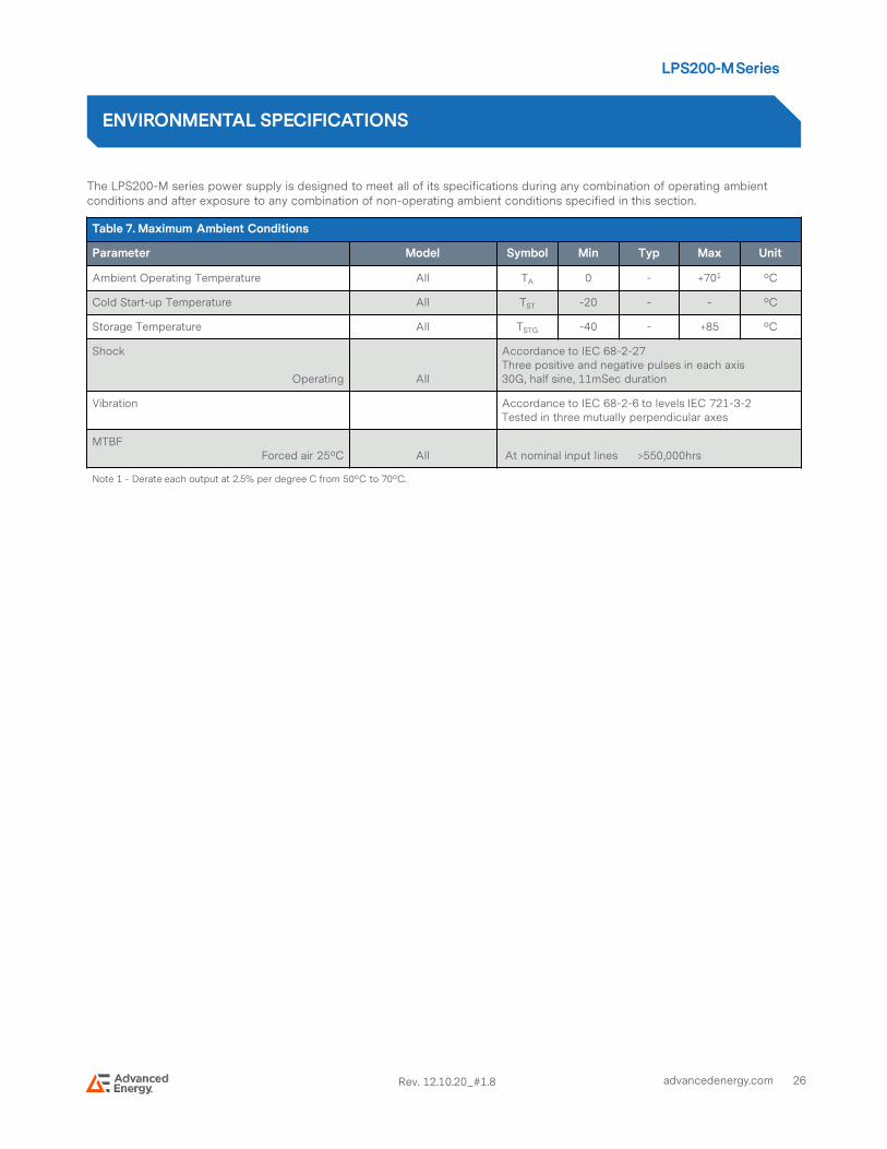
The LPS200-M series power supply is designed to meet all of its specifications during any combination of operating ambient conditions and after exposure to any combination of non-operating ambient conditions specified in this section.
ENVIRONMENTAL SPECIFICATIONS
Table 7. Maximum Ambient Conditions
Parameter Model Symbol Min Typ Max Unit
Ambient Operating Temperature All TA 0 - +701 ºC
Cold Start-up Temperature All TST -20 - - ºC
Storage Temperature All TSTG -40 - +85 ºC
Shock
Operating All
Accordance to IEC 68-2-27Three positive and negative pulses in each axis 30G, half sine, 11mSec duration
Vibration Accordance to IEC 68-2-6 to levels IEC 721-3-2Tested in three mutually perpendicular axes
MTBFForced air 25ºC All At nominal input lines >550,000hrs
Note 1 - Derate each output at 2.5% per degree C from 50ºC to 70ºC.

LPS200-M Series
27advancedenergy.com Rev. 12.10.20_#1.8
AC Input (SK1)
This connector supplies the AC Mains to the LPS200-M series power supply.
Pin 1 - Neutral
Pin 3 – Line
Earth Ground (GND)
This tab connector is the safety ground connection and should be connected to AC input earth ground.
GND - Earth Ground (Safety Ground)
Main Output (SK2)
These terminals provide the main output for the LPS200-M.
TB-1 - Common
TB-2 - Main output
Vo Output voltage adjustment
The main output of the LPS200-M series power supply can be adjusted by +/- 10% from its nominal output voltage via the potentiometer VR1. Since the 12V Fan Supply is not independently regulated, its output voltage may change according to Vo setpoint.
10-Pin header connector (SK3)
The LPS200-M series power supply contains an isolated 12V output for powering a cooling fan or as a aux power source. This 12V Fan Supply is provided by pin9/pin10 of header connector SK3.
Pin 1 – +Remote Sense
Pin 2 – -Remote Sense
Pin 3 – NC
Pin 4 – NC
Pin 5 – Power Fail
Pin 6 – Common
Pin 7 – NC
Pin 8 – Common
Pin 9 – +12V Fan
Pin 10 – -12V Fan Return
POWER AND CONTROL SIGNAL DESCRIPTIONS
LPS200-M Series
28advancedenergy.com Rev. 12.10.20_#1.8
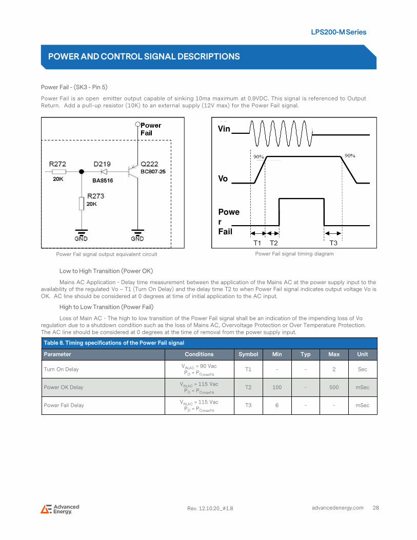
Power Fail - (SK3 - Pin 5)
Power Fail is an open emitter output capable of sinking 10ma maximum at 0.9VDC. This signal is referenced to Output Return. Add a pull-up resistor (10K) to an external supply (12V max) for the Power Fail signal.
Low to High Transition (Power OK)
Mains AC Application - Delay time measurement between the application of the Mains AC at the power supply input to the availability of the regulated Vo – T1 (Turn On Delay) and the delay time T2 to when Power Fail signal indicates output voltage Vo is OK. AC line should be considered at 0 degrees at time of initial application to the AC input.
High to Low Transition (Power Fail)
Loss of Main AC - The high to low transition of the Power Fail signal shall be an indication of the impending loss of Vo regulation due to a shutdown condition such as the loss of Mains AC, Overvoltage Protection or Over Temperature Protection. The AC line should be considered at 0 degrees at the time of removal from the power supply input.
POWER AND CONTROL SIGNAL DESCRIPTIONS
Vin
Vo
Power Fail signal timing diagram
PowerFail
Power Fail signal output equivalent circuit
Table 8. Timing specifications of the Power Fail signal
Parameter Conditions Symbol Min Typ Max Unit
Turn On DelayVIN,AC = 90 VacPO = PO,maxFA
T1 - - 2 Sec
Power OK DelayVIN,AC = 115 Vac
PO = PO,maxFA
T2 100 - 500 mSec
Power Fail DelayVIN,AC = 115 Vac
PO = PO,maxFA
T3 6 - - mSec

LPS200-M Series
29advancedenergy.com Rev. 12.10.20_#1.8
+Remote Sense, -Remote Sense (Remote Sensing) – (SK3 – Pin 1 and Pin 2)
The main output of the LPS200-M series power supply is equipped with a Remote Sensing capability that will compensate for a voltage drop of up to a 0.5V between the output terminals of the supply and the sensed voltage point (load). This feature is implemented by connecting the Vo +Remote Sense (pin 1) and the Vo –Remote Sense (pin 2) terminals to the positive and negative rails of the main output, respectively, at a location that is near to the load. Care should be taken inthe routing of the sense lines as any noise sources or additional filtering components introduced into the voltage rail may affect the stability of the power supply. The LPS200-M series power supply will operate appropriately without the sense lines connected; however it is recommended that the sense lines be connected directly to the main output terminals if remote sensing is not required.
The power supply is protected against damage caused by inadvertent reverse connection of the Remote Sense lines.
Remote sensing has no effect on the +12V FAN output.
Note: The maximum output voltage of the LPS200-M series power supply is limited to +10% above the nominal setting, trimming the main output above the nominal may limit the maximum amount of voltage sense compensation.
POWER AND CONTROL SIGNAL DESCRIPTIONS
LPS200-M Series
30advancedenergy.com Rev. 12.10.20_#1.8
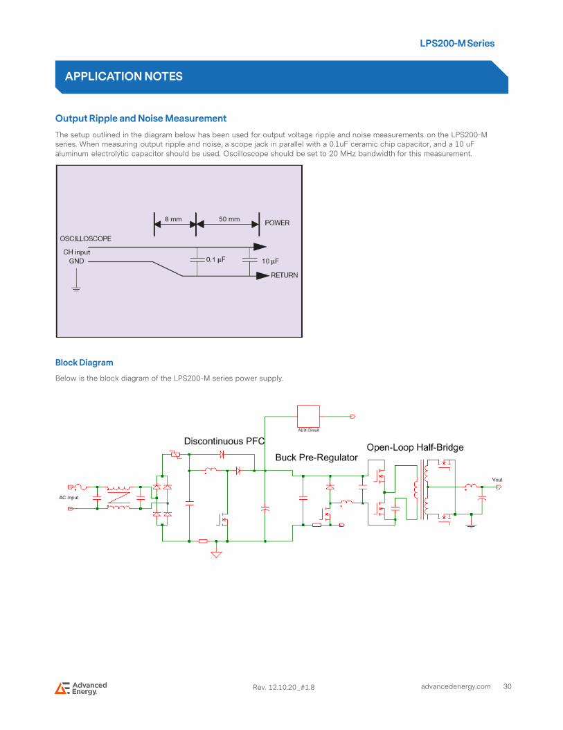
Output Ripple and Noise Measurement
The setup outlined in the diagram below has been used for output voltage ripple and noise measurements on the LPS200-M series. When measuring output ripple and noise, a scope jack in parallel with a 0.1uF ceramic chip capacitor, and a 10 uFaluminum electrolytic capacitor should be used. Oscilloscope should be set to 20 MHz bandwidth for this measurement.
Block Diagram
Below is the block diagram of the LPS200-M series power supply.
APPLICATION NOTES

LPS200-M Series
31advancedenergy.com Rev. 12.10.20_#1.8
RECORD OF REVISION AND CHANGES
IssueIssueIssueIssue DateDateDateDate DescriptionDescriptionDescriptionDescription OriginatorsOriginatorsOriginatorsOriginators
1.1 10.17.2011 First Issue J. Zhu
1.2 10.02.2014 Update thermal derating curve K. Wang
1.3 09.23.2015 Add “Input AC /DC Under Voltage Lockout Voltage” in Table 2 K. Wang
1.4 10.28.2015 Change the word "Emerson” to “Artesyn” K. Wang
1.5 12.13.2016 Update the weight information K. Wang
1.6 03.15.2017 Add the recommended screw torque K. Wang
1.7 06.12.2017 Update the OCP format K. Wang
1.8 06.18.2020 Update safety cert from 60950 to 62368 K. Wang
1.9 12.10.2020 Update pin definition for fan Return K. Wang

AIF06ZPFC
LPS200-M - Rev. 12.10.20_#1.8
For international contact information,
visit advancedenergy.com.
[email protected] (Sales Support)
[email protected] (Technical Support)
+1 888 412 7832
ABOUTADVANCEDENERGY
Advanced Energy (AE) has devoted more than three
decades to perfecting power for its global customers. AE
designs and manufactures highly engineered, precision
power conversion, measurement and control solutions for
mission-critical applications and processes.
Our products enable customer innovation in complex
applications for a wide range of industries including
semiconductor equipment, industrial, manufacturing,
telecommunications, data center computing, and medical.
With deep applications know-how and responsive service
and support across the globe, we build collaborative
partnerships to meet rapid technological developments,
propel growth for our customers, and innovate the future
of power.
Specifications are subject to changewithout notice. Not responsible
for errors or omissions.©2020 Advanced Energy Industries, Inc. All rights
reserved. Advanced Energy®, andAE® are U.S. trademarks
of Advanced Energy Industries, Inc.