Embed Size (px)
Citation preview
Article ID: 5069
Configuring Advanced Radio Settings on
the WAP371
Objective
Radio settings are used to configure the wireless radio antenna and its properties on
the wireless access point (WAP) device so that communications can be fast,
congestion free, and tailored to the desired network setup. This configuration is
helpful in a situation where the WAP is surrounded by other WAPs, and settings like
channel mode and frequency need to be changed to achieve smooth communication.
If multiple WAPs in close proximity are broadcasting at the same frequency or
channel, the transmitted data can become corrupted or canceled out, which greatly
decreases performance.
The objective of this document is to explain how to configure Advanced Radio
Settings on the WAP371 Access Point.
Note: For information on how to configure Basic Radio Settings on the WAP371, refer
to the article Basic Radio Settings on the WAP371.
Applicable Devices
WAP371
Software Version
v1.1.2.3
Configuring Advanced Radio Settings
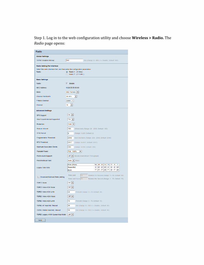
Step 1. Log in to the web configuration utility and choose Wireless > Radio. The
Radio page opens:
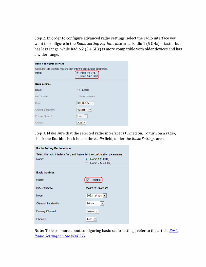
Step 2. In order to configure advanced radio settings, select the radio interface you
want to configure in the Radio Setting Per Interface area. Radio 1 (5 GHz) is faster but
has less range, while Radio 2 (2.4 GHz) is more compatible with older devices and has
a wider range.
Step 3. Make sure that the selected radio interface is turned on. To turn on a radio,
check the Enable check box in the Radio field, under the Basic Settings area.
Note: To learn more about configuring basic radio settings, refer to the article Basic
Radio Settings on the WAP371.
Note: If you are enabling Radio 1 (5 GHz) with 80 MHz bandwidth, a notice will
appear warning that this configuration may draw more power than can be delivered
by IEEE 802.3af PoE standards. If the WAP is being powered PoE, switch to a power
adapter or an IEEE 802.3at PSE (Power Source Equipment). Click OK to continue.
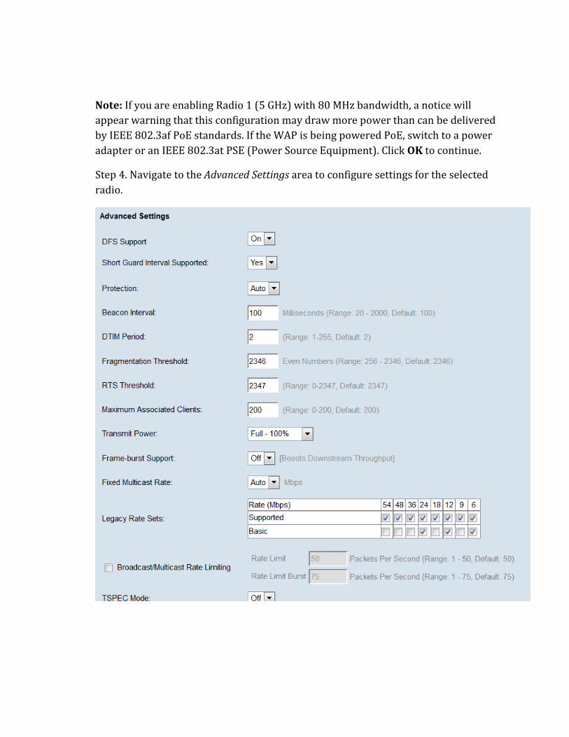
Step 4. Navigate to the Advanced Settings area to configure settings for the selected
radio.
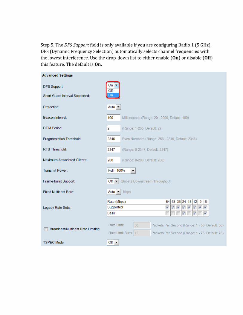
Step 5. The DFS Support field is only available if you are configuring Radio 1 (5 GHz).
DFS (Dynamic Frequency Selection) automatically selects channel frequencies with
the lowest interference. Use the drop-down list to either enable (On) or disable (Off)
this feature. The default is On.
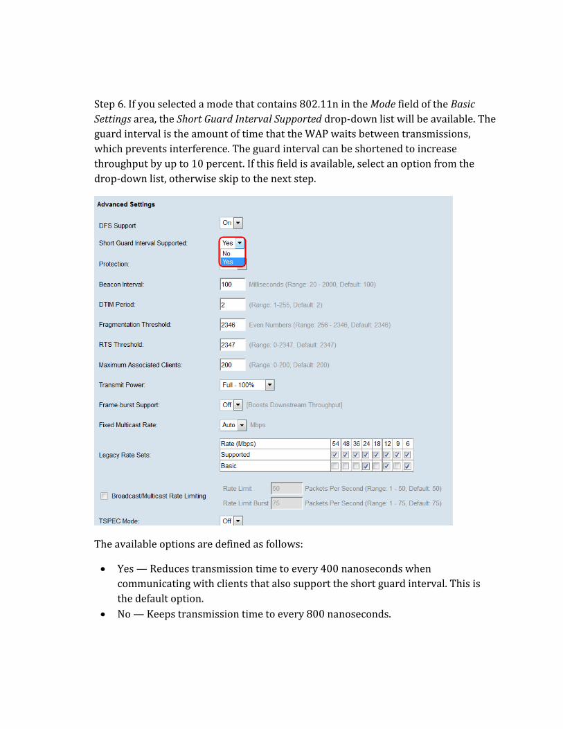
Step 6. If you selected a mode that contains 802.11n in the Mode field of the Basic
Settings area, the Short Guard Interval Supported drop-down list will be available. The
guard interval is the amount of time that the WAP waits between transmissions,
which prevents interference. The guard interval can be shortened to increase
throughput by up to 10 percent. If this field is available, select an option from the
drop-down list, otherwise skip to the next step.
The available options are defined as follows:
Yes — Reduces transmission time to every 400 nanoseconds when
communicating with clients that also support the short guard interval. This is
the default option.
No — Keeps transmission time to every 800 nanoseconds.
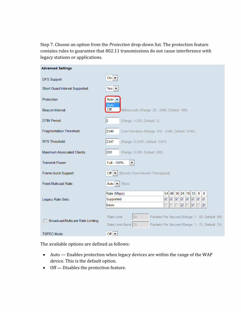
Step 7. Choose an option from the Protection drop-down list. The protection feature
contains rules to guarantee that 802.11 transmissions do not cause interference with
legacy stations or applications.
The available options are defined as follows:
Auto — Enables protection when legacy devices are within the range of the WAP
device. This is the default option.
Off — Disables the protection feature.

Step 8. In the Beacon Interval field, enter the interval of milliseconds between beacon
frame transmissions. Beacon frames announce the existence of the wireless network.
The value must be between 20 to 2000 milliseconds. The default behavior is to send a
beacon frame once every 100 milliseconds. It is recommended to not change this
value, as a misconfigured beacon interval can cause clients to be unable to connect.
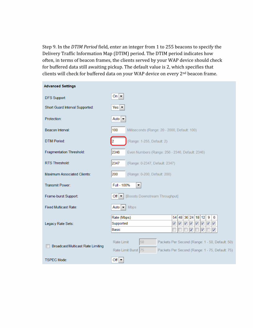
Step 9. In the DTIM Period field, enter an integer from 1 to 255 beacons to specify the
Delivery Traffic Information Map (DTIM) period. The DTIM period indicates how
often, in terms of beacon frames, the clients served by your WAP device should check
for buffered data still awaiting pickup. The default value is 2, which specifies that
clients will check for buffered data on your WAP device on every 2nd beacon frame.
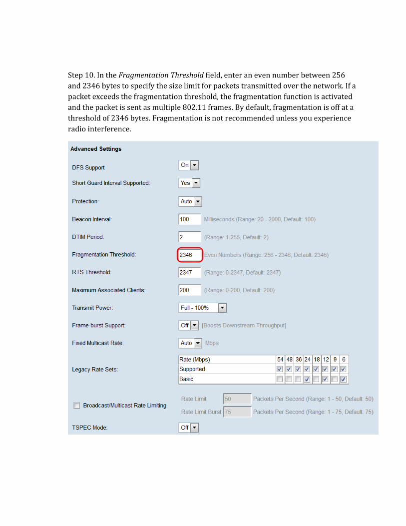
Step 10. In the Fragmentation Threshold field, enter an even number between 256
and 2346 bytes to specify the size limit for packets transmitted over the network. If a
packet exceeds the fragmentation threshold, the fragmentation function is activated
and the packet is sent as multiple 802.11 frames. By default, fragmentation is off at a
threshold of 2346 bytes. Fragmentation is not recommended unless you experience
radio interference.
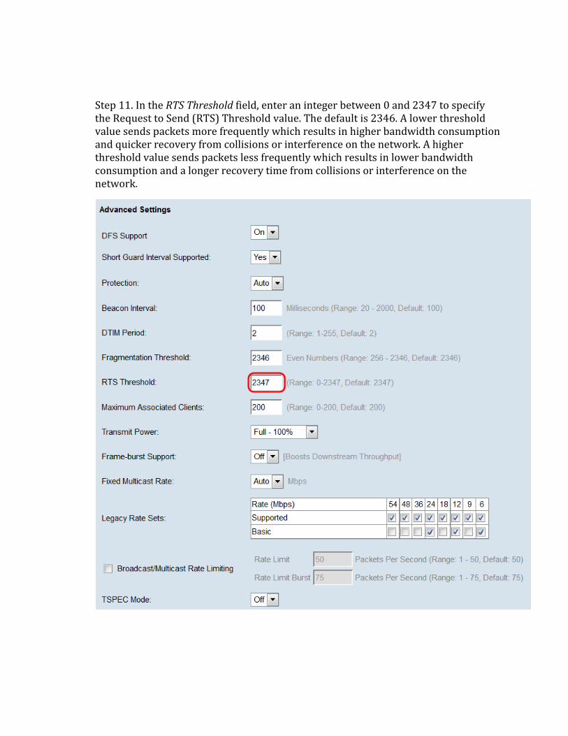
Step 11. In the RTS Threshold field, enter an integer between 0 and 2347 to specify the Request to Send (RTS) Threshold value. The default is 2346. A lower threshold value sends packets more frequently which results in higher bandwidth consumption and quicker recovery from collisions or interference on the network. A higher threshold value sends packets less frequently which results in lower bandwidth consumption and a longer recovery time from collisions or interference on the network.
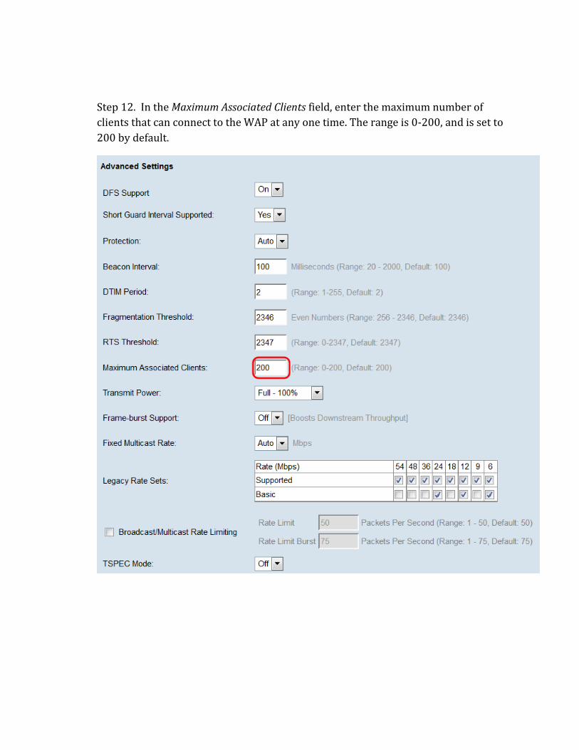
Step 12. In the Maximum Associated Clients field, enter the maximum number of
clients that can connect to the WAP at any one time. The range is 0-200, and is set to
200 by default.
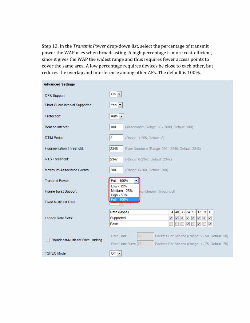
Step 13. In the Transmit Power drop-down list, select the percentage of transmit
power the WAP uses when broadcasting. A high percentage is more cost-efficient,
since it gives the WAP the widest range and thus requires fewer access points to
cover the same area. A low percentage requires devices be close to each other, but
reduces the overlap and interference among other APs. The default is 100%.
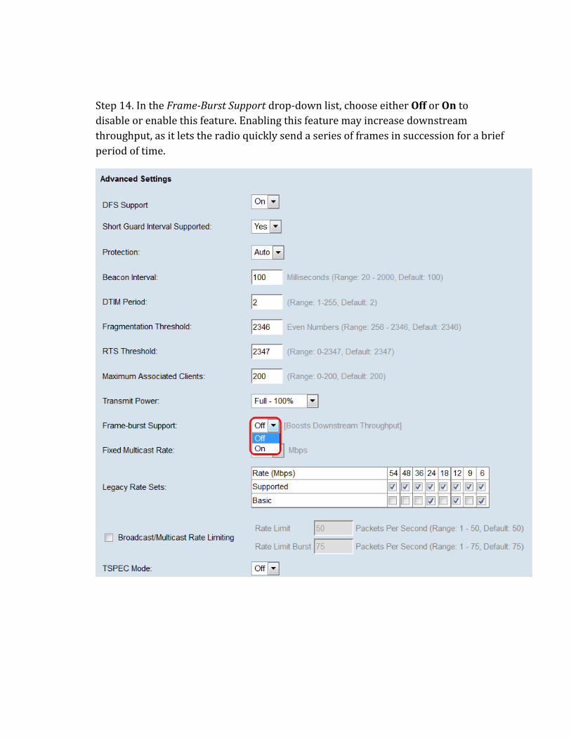
Step 14. In the Frame-Burst Support drop-down list, choose either Off or On to
disable or enable this feature. Enabling this feature may increase downstream
throughput, as it lets the radio quickly send a series of frames in succession for a brief
period of time.
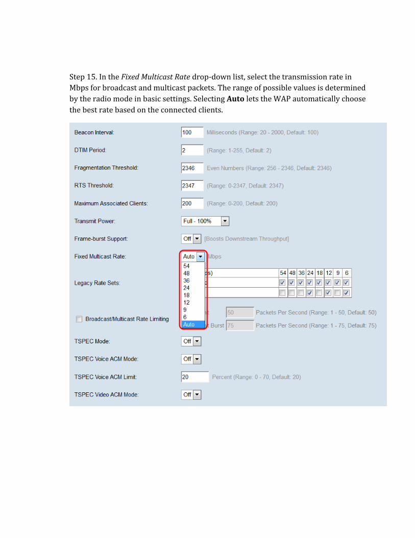
Step 15. In the Fixed Multicast Rate drop-down list, select the transmission rate in
Mbps for broadcast and multicast packets. The range of possible values is determined
by the radio mode in basic settings. Selecting Auto lets the WAP automatically choose
the best rate based on the connected clients.
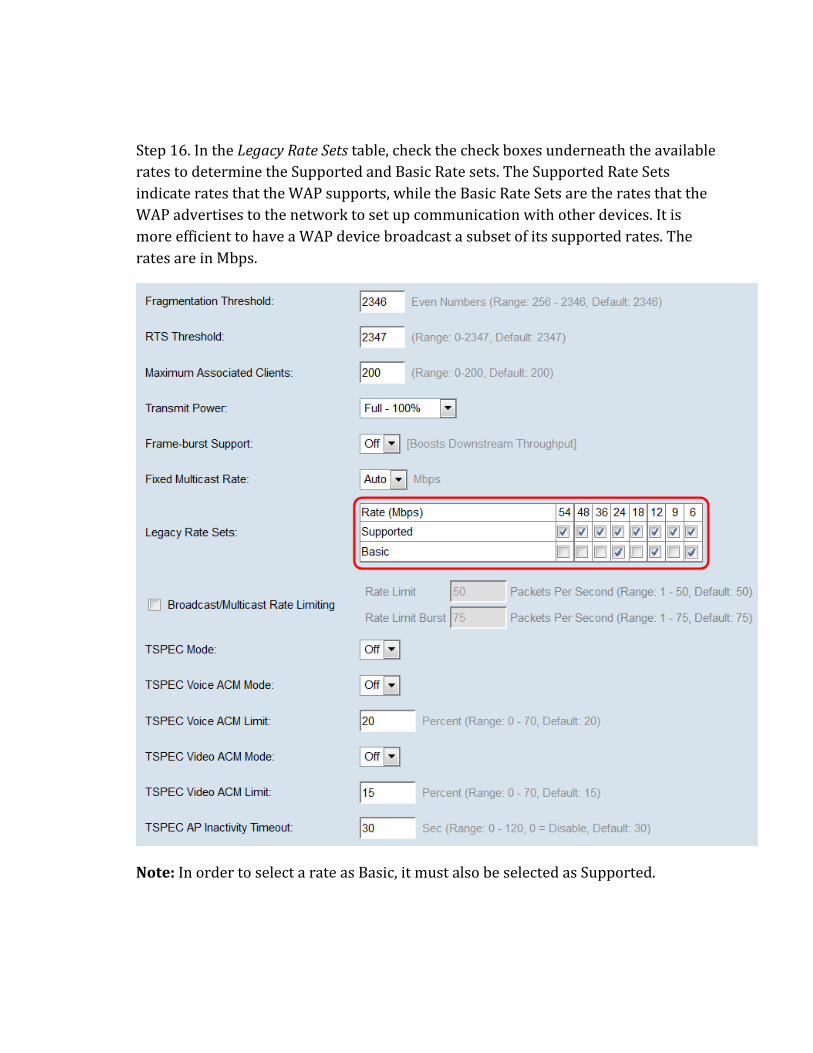
Step 16. In the Legacy Rate Sets table, check the check boxes underneath the available
rates to determine the Supported and Basic Rate sets. The Supported Rate Sets
indicate rates that the WAP supports, while the Basic Rate Sets are the rates that the
WAP advertises to the network to set up communication with other devices. It is
more efficient to have a WAP device broadcast a subset of its supported rates. The
rates are in Mbps.
Note: In order to select a rate as Basic, it must also be selected as Supported.
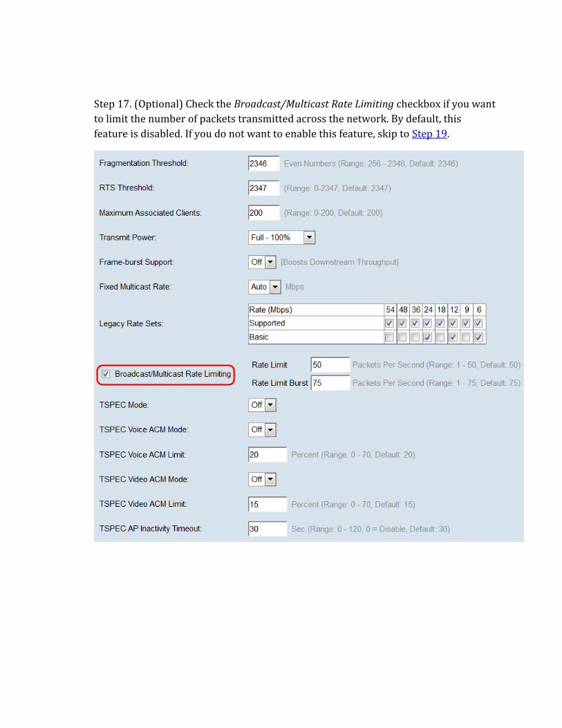
Step 17. (Optional) Check the Broadcast/Multicast Rate Limiting checkbox if you want
to limit the number of packets transmitted across the network. By default, this
feature is disabled. If you do not want to enable this feature, skip to Step 19.
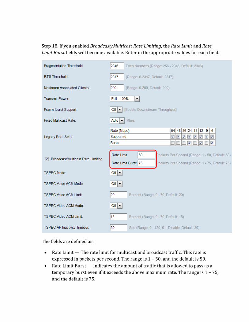
Step 18. If you enabled Broadcast/Multicast Rate Limiting, the Rate Limit and Rate
Limit Burst fields will become available. Enter in the appropriate values for each field.
The fields are defined as:
Rate Limit — The rate limit for multicast and broadcast traffic. This rate is
expressed in packets per second. The range is 1 – 50, and the default is 50.
Rate Limit Burst — Indicates the amount of traffic that is allowed to pass as a
temporary burst even if it exceeds the above maximum rate. The range is 1 – 75,
and the default is 75.
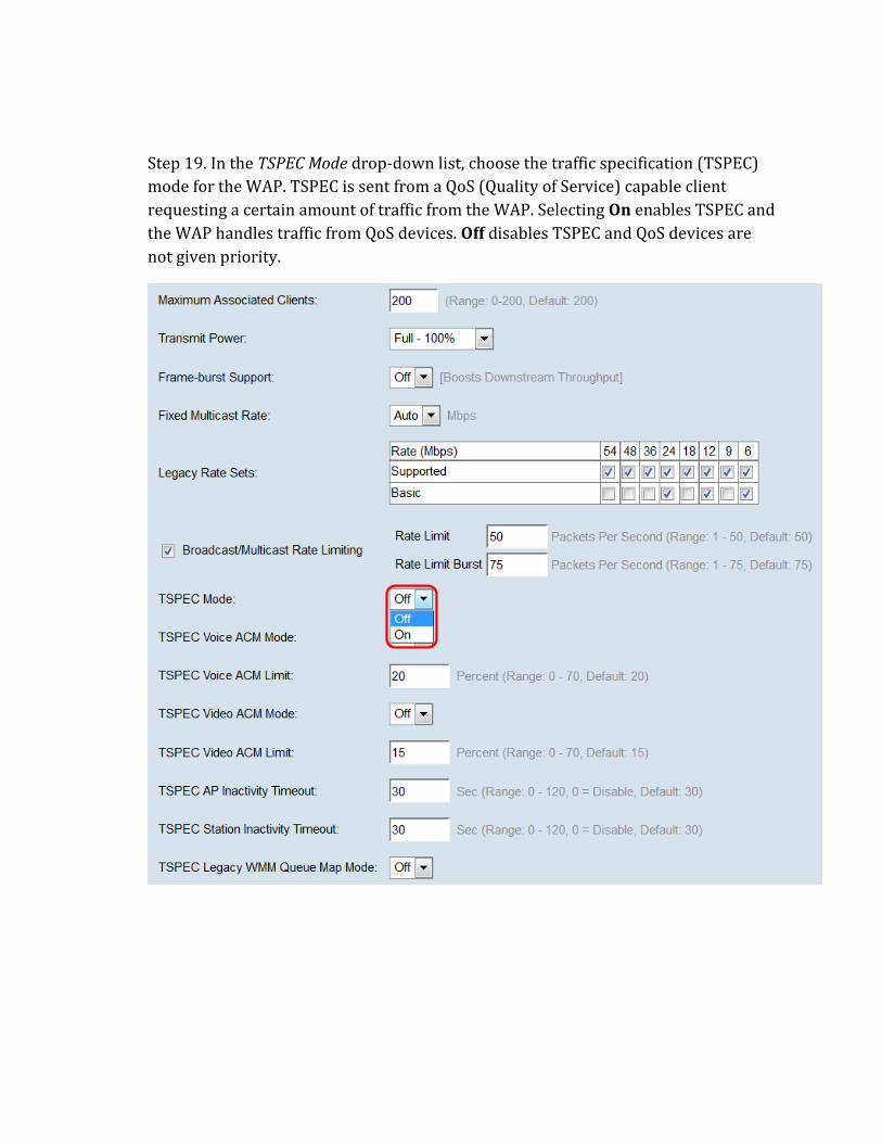
Step 19. In the TSPEC Mode drop-down list, choose the traffic specification (TSPEC)
mode for the WAP. TSPEC is sent from a QoS (Quality of Service) capable client
requesting a certain amount of traffic from the WAP. Selecting On enables TSPEC and
the WAP handles traffic from QoS devices. Off disables TSPEC and QoS devices are
not given priority.
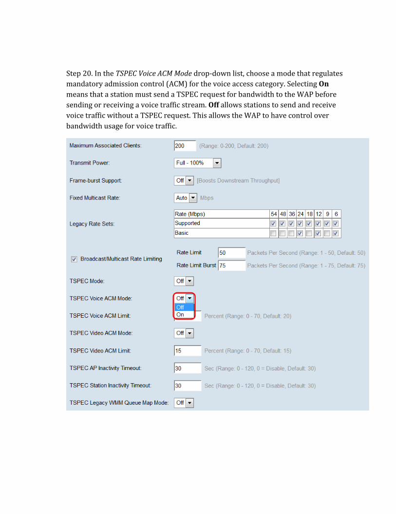
Step 20. In the TSPEC Voice ACM Mode drop-down list, choose a mode that regulates
mandatory admission control (ACM) for the voice access category. Selecting On
means that a station must send a TSPEC request for bandwidth to the WAP before
sending or receiving a voice traffic stream. Off allows stations to send and receive
voice traffic without a TSPEC request. This allows the WAP to have control over
bandwidth usage for voice traffic.
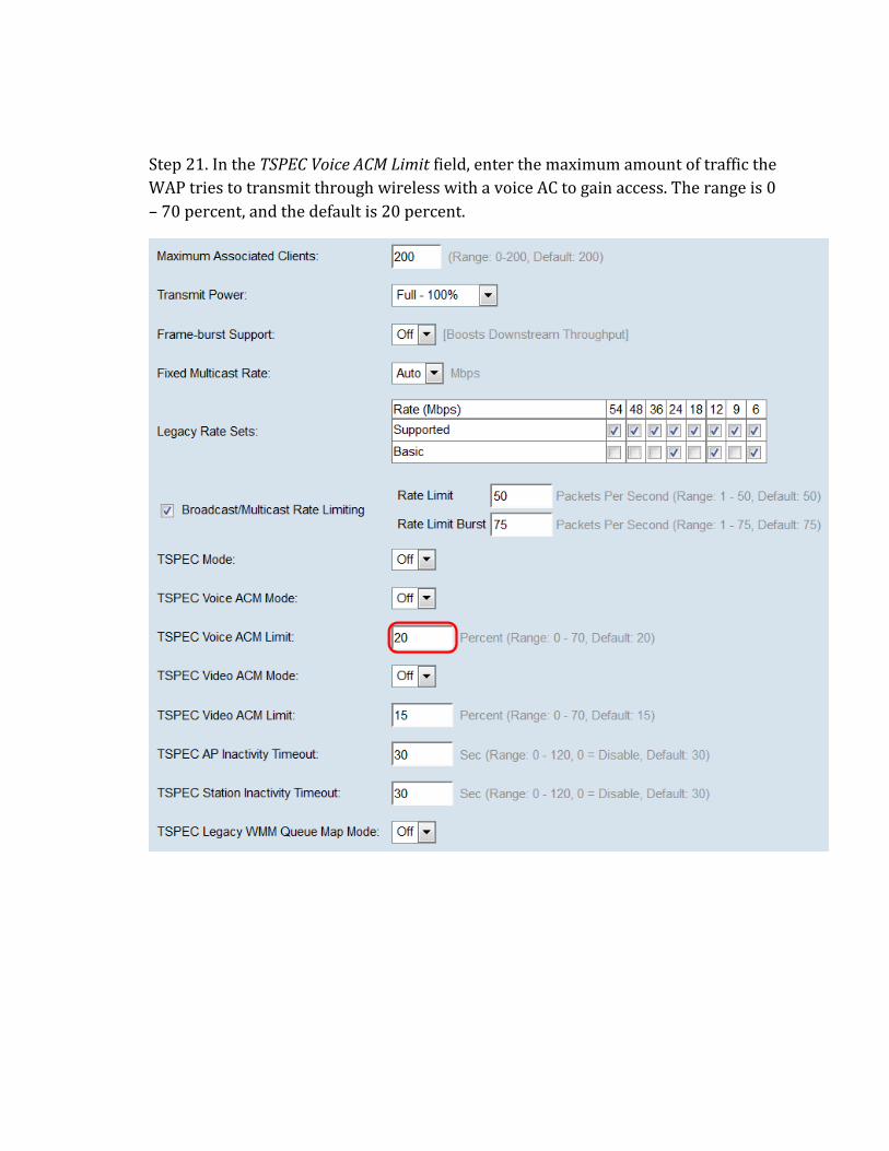
Step 21. In the TSPEC Voice ACM Limit field, enter the maximum amount of traffic the
WAP tries to transmit through wireless with a voice AC to gain access. The range is 0
– 70 percent, and the default is 20 percent.
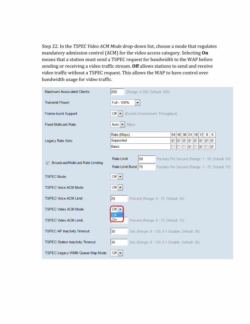
Step 22. In the TSPEC Video ACM Mode drop-down list, choose a mode that regulates
mandatory admission control (ACM) for the video access category. Selecting On
means that a station must send a TSPEC request for bandwidth to the WAP before
sending or receiving a video traffic stream. Off allows stations to send and receive
video traffic without a TSPEC request. This allows the WAP to have control over
bandwidth usage for video traffic.
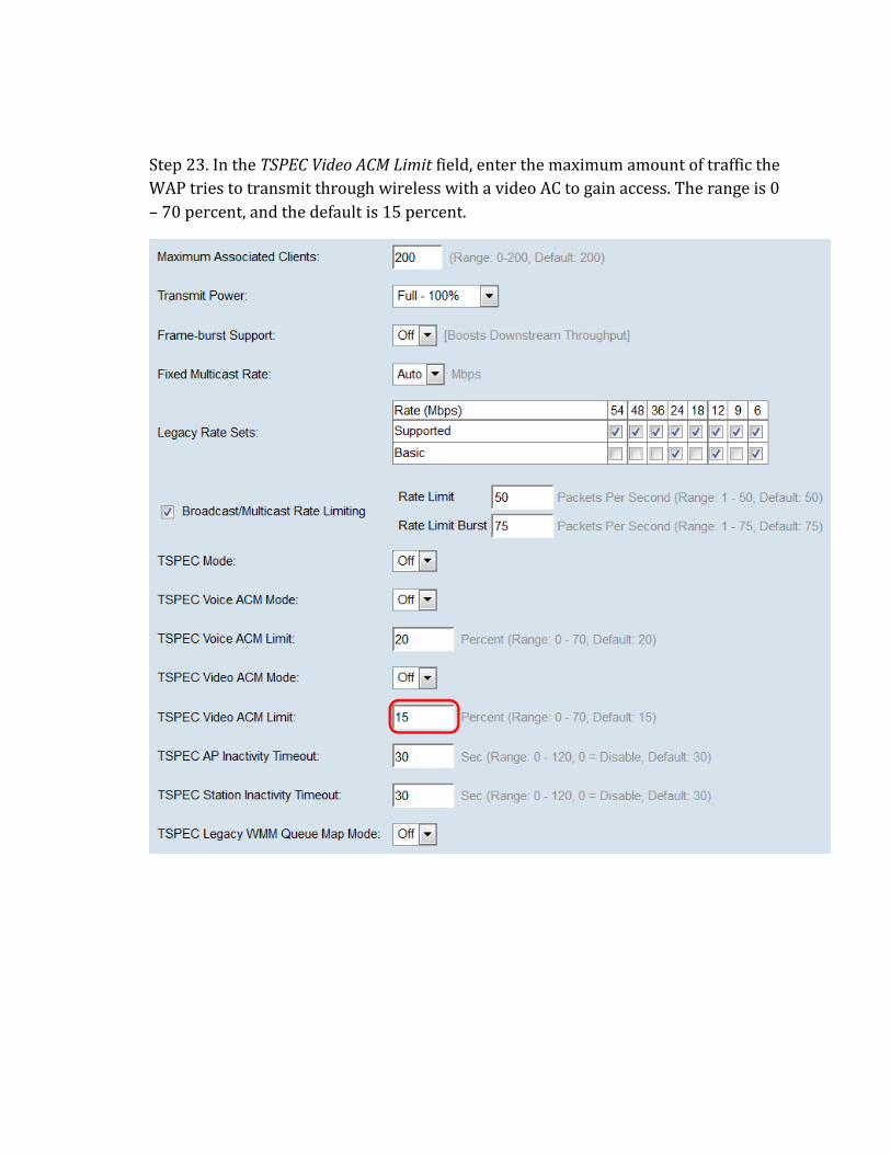
Step 23. In the TSPEC Video ACM Limit field, enter the maximum amount of traffic the
WAP tries to transmit through wireless with a video AC to gain access. The range is 0
– 70 percent, and the default is 15 percent.
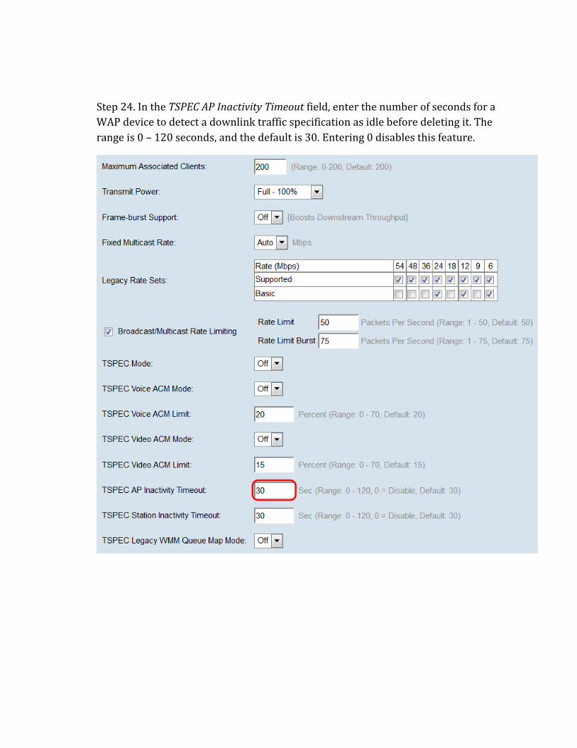
Step 24. In the TSPEC AP Inactivity Timeout field, enter the number of seconds for a
WAP device to detect a downlink traffic specification as idle before deleting it. The
range is 0 – 120 seconds, and the default is 30. Entering 0 disables this feature.
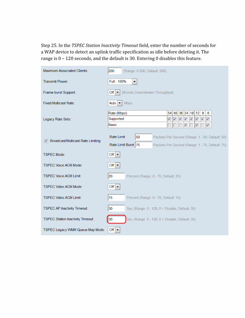
Step 25. In the TSPEC Station Inactivity Timeout field, enter the number of seconds for
a WAP device to detect an uplink traffic specification as idle before deleting it. The
range is 0 – 120 seconds, and the default is 30. Entering 0 disables this feature.
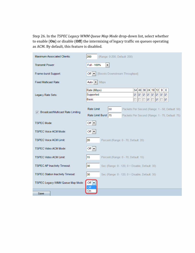
Step 26. In the TSPEC Legacy WMM Queue Map Mode drop-down list, select whether
to enable (On) or disable (Off) the intermixing of legacy traffic on queues operating
as ACM. By default, this feature is disabled.
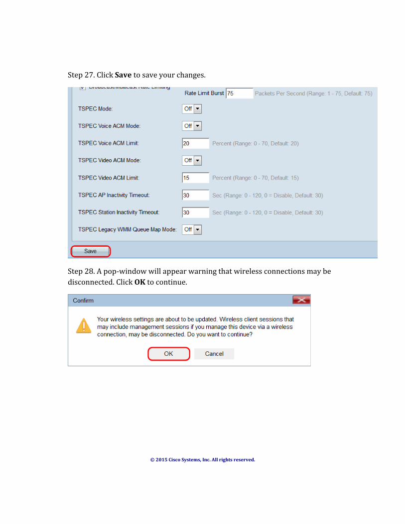
Step 27. Click Save to save your changes.
Step 28. A pop-window will appear warning that wireless connections may be
disconnected. Click OK to continue.
© 2015 Cisco Systems, Inc. All rights reserved.