Embed Size (px)
Citation preview
8/10/2019 Article Kim 2009 Suppression in Electrical Facilities
http://slidepdf.com/reader/full/article-kim-2009-suppression-in-electrical-facilities 1/15
http://www.nrc-cnrc.gc.ca/irc
Fire and explosion protection of electrical installations with new
advanced suppression systems
NRCC - 5 1 2 3 5
K i m , A . K .
D e c e m b e r 2 0 0 9
A version of this document is published in / Une version de ce document se trouve dans:
Hazardous Areas Conference 2009, Calgary, AB, June 17-18, 2009, pp. 1-13
The material in this document is covered by the provisions of the Copyright Act, by Canadian laws, policies, regulations and international
agreements. Such provisions serve to identify the information source and, in specific instances, to prohibit reproduction of materials withoutwritten permission. For more information visit http://laws.justice.gc.ca/en/showtdm/cs/C-42
Les renseignements dans ce document sont protégés par la Loi sur le droit d'auteur, par les lois, les politiques et les règlements du Canada etdes accords internationaux. Ces dispositions permettent d'identifier la source de l'information et, dans certains cas, d'interdire la copie dedocuments sans permission écrite. Pour obtenir de plus amples renseignements : http://lois.justice.gc.ca/fr/showtdm/cs/C-42

8/10/2019 Article Kim 2009 Suppression in Electrical Facilities
http://slidepdf.com/reader/full/article-kim-2009-suppression-in-electrical-facilities 2/15
8/10/2019 Article Kim 2009 Suppression in Electrical Facilities
http://slidepdf.com/reader/full/article-kim-2009-suppression-in-electrical-facilities 3/15
FIRE AND EXPLOSION PROTECTION OF ELECTRICAL INSTALLATIONS
WITH NEW ADVANCED SUPPRESSION SYSTEMS
by
Andrew Kim*
Abstract
There is a potential for a very large fire or explosion when using electrical equipment
in areas where flammable gases could accumulate or in room containing power transformers.
Recently, several new fire suppression technologies have been developed to provide
protection in an environment with an explosive atmosphere or to provide suppression of a
large fire involving electrical equipment, such as power transformers.
The National Research Council of Canada (NRC) has carried out projects to evaluate
the fire and explosion protection effectiveness of new technologies. In one project, the
explosion suppression effectiveness of hybrid gas generators in providing safety to occupants
in a compartment against a deflagration type explosion was evaluated. Hybrid gas generator
systems combine gas generator technology with a liquid fire suppression agent. Three hybrid
gas generator systems evaluated used HFC-227ea (FM-200), Novec1230, and water as
suppression agents, respectively. Several aspects of the systems, such as toxicity issues, and
the effect of additives on the suppression performance, were studied.
In another project, the effectiveness of a newly developed compressed-air-foam (CAF)
system was evaluated for power transformer applications. The performance of the CAF
system was compared to that of sprinkler system, which is the current NFPA (National Fire
Protection Association) fire protection requirement for protecting power transformers.
INTRODUCTION
There is a potential for a very large fire or explosion when using electrical equipment
in areas where flammable gases could accumulate or in room containing power transformers.
Recently, several new fire suppression technologies have been developed to provide
protection in an environment with an explosive atmosphere or to provide suppression of alarge fire involving electrical equipment, such as power transformers.
The National Research Council of Canada (NRC) has carried out projects to evaluate
the fire and explosion protection effectiveness of new technologies. In one project, the
explosion suppression effectiveness of hybrid gas generators in providing safety to occupants
in a compartment against a deflagration type explosion was evaluated. In another project, the
* Andrew Kim, Senior Research Officer, Fire Research Program, Bldg. M-59,
Institute for Research in Construction, National Research Council of Canada,
1200 Montreal Road, Ottawa, Ontario, K1A 0R6,
Phone #: (613) 993-9555e-mail: [email protected]
8/10/2019 Article Kim 2009 Suppression in Electrical Facilities
http://slidepdf.com/reader/full/article-kim-2009-suppression-in-electrical-facilities 4/15
effectiveness of a newly developed compressed-air-foam (CAF) system was evaluated for
power transformer applications.
This paper deals with both the explosion protection of flammable liquid fuels and fire
suppression of large fires involving power transformers.
EXPLOSION PROTECTION
In electrical installations, there is a potential for a deflagration type explosion because
of the presence of flammable liquids and high electric energy. Flammable liquid may leak
from its container, and it may be ignited if there is an electric arcing from a high-voltage
equipment, creating an explosive environment. There may be an occupant in the space, and
explosion in this space is a serious threat to the safety of the occupant.
In order to protect the occupants and equipment in the space, a deflagration type
explosion must be extinguished in a few hundred milliseconds. The key for explosion
suppression is to detect and arrest combustion while it is still in the incipient stage. This isachieved by rapidly discharging a suppressant to directly terminate the explosion reaction and
flame propagation before a destructive pressure rise is reached.
NRC has been working on projects to provide safety to occupants in a small
compartment, such as crew compartment of armoured vehicles, with new advanced fire
suppression systems. Even though the focus of the projects was armoured vehicle crew
compartment, the results applies to any space where deflagration type explosion may occur.
Experimental Set-up and Procedures
The real-scale explosion suppression experiments were conducted in a compartment
constructed to simulate the crew compartment of armoured vehicles. Three explosion
suppression systems, with full-system hardware including optical fire sensors and electronic
controller, were evaluated.
Test Compartment
A test compartment simulating the back half of an armoured vehicle crew
compartment was constructed to carry out explosion suppression experiments. The cross-
section area of the test compartment was 2.52 m2, and it was 1.5 m in length and the total
volume of the test compartment was 3.78 m
3
. The test compartment had an access door witha dimension of 1.04 m x 1.04 m. This door also acted as a pressure relief vent to protect the
compartment integrity.
Explosion Scenario
A fire explosion in the test compartment was generated with a fuel spray using a twin-
fluid (gasoline and air) nozzle (Securiplex 90o, 5L/min) and a hot wire ignition source.
Gasoline was used as the fuel. An electric igniter was used to ignite the fuel spray and
produce an explosion in the test compartment. Gasoline spray into the test compartment was
limited to a 2 - 3 s duration, however, air supply to the compartment through the twin fluid
nozzle was continuously maintained during the whole duration of the experiments. At thesame time, the hot wire igniter was maintained hot during the entire duration of the
8/10/2019 Article Kim 2009 Suppression in Electrical Facilities
http://slidepdf.com/reader/full/article-kim-2009-suppression-in-electrical-facilities 5/15
experiments to simulate the presence of hot fragments. A continuous supply of air and the
presence of the hot ignition wire increased the possibility of re-ignition, resulting in a very
challenging scenario for explosion suppression.
Explosion Extinguishing Systems
Three types of hybrid gas generator systems for suppressing explosions were used in
the experiments. Hybrid gas generator systems combine gas generator technology with a
liquid fire suppression agent. The three liquid fire suppression agents were HFC-227ea
whose brand name is FM-200, Novec1230, and water. These hybrid extinguishers apply a
novel method to deliver suppression agents. A gas generator can produce a large quantity of
inert gases (mainly N2, CO2 and H2O vapour) by combustion of solid propellants. The heat
and pressure generated by the combustion of the propellant in the gas generator are used to
heat and expel the suppression agent (FM-200, Novec1230 or water). The super fast
discharge of a large quantity of inert gases, combined with the fire suppression action of the
agent, is used to provide explosion protection for the crew compartment.
The hybrid gas generator systems with their flame detectors were mounted on the wall
of the test compartment, opposite to the fuel spray. A high-speed optical triple IR flame
detector was used to detect the initiation of the explosion in the test compartment.
For the hybrid gas generator with FM-200 tests, the maximum capacity of the hybrid
fire extinguisher was approximately 1.5 L, and the amount of FM-200 contained in the
extinguisher was 2.26 kg, enough to produce a 7% concentration in the test compartment. For
the hybrid gas generator with water tests, the maximum capacity of the hybrid fire
extinguisher was 1.5 L in an initial test. However, since the extinguisher did not perform well
in the test, the size of the extinguisher was increased to 2.25 L in subsequent tests.
For the hybrid gas generator with Novec1230 tests, two sizes of hybrid fire
extinguisher were used, because several different concentrations of Novec1230 was tried in
the tests. The maximum capacity of the smaller fire extinguisher was 1.5 L, and the
maximum capacity of the larger fire extinguisher was 2.5 L. The amount of Novec1230 used
in the tests varied between 2.4 kg to 4.0 kg. These amounts were sufficient to produce 4.45%
to 7.2% concentration in the test compartment.
In some of the tests, additive was used to evaluate its effect on explosion suppression
capability. The additive used in the hybrid gas generators with FM-200 and Novec1230 was
sodium bicarbonate, and the additive used in the hybrid gas generator with water was potassium acetate.
Experimental Results and Discussion
Experiments were carried out to study the performance of three hybrid gas generator
systems in extinguishing explosions in the test compartment with and without additives.
Explosion Experiments without Suppression
Baseline experiments were conducted to determine the explosion conditions in the test
compartment, such as fire size, maximum compartment temperature and pressure, and to
8/10/2019 Article Kim 2009 Suppression in Electrical Facilities
http://slidepdf.com/reader/full/article-kim-2009-suppression-in-electrical-facilities 6/15
evaluate the potential damage caused by explosion incidents when it was not protected by
the suppression system.
The results indicated that although only a small amount of fuel was involved, the
explosion in the compartment was quite severe, creating high temperatures and large
overpressure, as well as low oxygen and high CO and CO2 levels in the compartment. Forexample, the maximum temperatures generated in the experiments ranged from 820 to
1020oC, and the maximum overpressure from 1050 to 2300 Pa. The minimum oxygen
concentrations in the experiments ranged from 8.96 to 13.37%, depending on the amount of
fuel discharged into the compartment. The test showed that with this type of explosion, the
equipment and personnel in the test compartment would have little chance of survival, when
no protection was provided.
Explosion Suppression with FM-200
In one of the experiments, one hybrid gas generator extinguisher containing 2.26 kg of
FM-200, which would produce 7% concentration in the test compartment, was used. Thenozzle of the extinguisher was aimed towards the fire source located at one corner of the
compartment. No obstacle was placed in the compartment.
The fire ignited at 113 ms after the fuel discharge, and the agent discharge activated at
46 ms after the fire ignition. The explosion was extinguished at 228 ms after the ignition.
However, the fire re-ignited at 2840 ms after the first explosion was extinguished. At the re-
ignition moment, both the agent and fuel discharge into the compartment were completed, but
the igniter was still maintained hot.
Since the level of thermal decomposition products generated during suppression was
determined by the fire intensity and the duration of the reaction time between the agent and
flame, the re-ignition resulted in very high HF and COF2 concentrations in the compartment.
The average HF concentration over a 2 min period in the experiment was approximately
5,000 ppm. At the same time, the oxygen concentration in the compartment dropped to 10%,
and CO and CO2 concentrations exceeded 1.0 and 4.0%, respectively.
In order to evaluate the impact of discharge direction on the explosion suppression, the
direction of the extinguisher nozzle was adjusted to aim sideways toward the back of the
compartment. With the nozzle direction changed to aim sideways, the explosion was
extinguished at 153 ms after the ignition, and there was no re-ignition in the compartment.
The suppression performance of the hybrid gas generator/FM-200 extinguisher with nozzleaiming sideways was significantly better than with nozzle aimed at the fire source.
Since the explosion was quickly extinguished, the amount of thermal decomposition
products generated in the experiment was very small. The 2-min average HF concentration
was 61 ppm. The average COF2 concentration was 24 ppm.
When an obstacle, which was a 254 mm diameter tube, was located between the fire
source and the extinguisher, it created a much more challenging condition in the test
compartment for the explosion suppression systems.
With the nozzle of the extinguisher aimed directly towards the center of the obstacle,the hybrid gas generator/FM-200 extinguisher extinguished the explosion at 189 ms after
8/10/2019 Article Kim 2009 Suppression in Electrical Facilities
http://slidepdf.com/reader/full/article-kim-2009-suppression-in-electrical-facilities 7/15
ignition. However, the fire re-ignited at 1336 ms after the first explosion was extinguished.
Since the explosion re-ignited, HF and COF2 concentrations in the compartment were very
high. The 2-min average HF concentration was 5063 ppm, and the average COF2
concentration was 4947 ppm.
When the nozzle direction of the hybrid extinguisher was changed to aim sidewaystowards the back of the compartment, it performed better. The hybrid extinguisher
extinguished the explosion at 206 ms after ignition. However, the fuel re-ignited at 2259 ms
after the first explosion was extinguished. At re-ignition, there was no fuel discharge into the
compartment but the igniter was still maintained hot. The re-ignited flame was very small
and limited to around the igniter, and self-extinguished quickly. As a result, the amount of
thermal decomposition products generated in this experiment was much less than the amount
in previous experiment with the nozzle aimed at the obstacle. The average HF concentration
was 1616 ppm, and the average COF2 concentration was 676 ppm.
To evaluate the effect of an additive on the explosion suppression and the generation
of thermal decomposition products, full-scale experiments were carried out using sodium bicarbonate as an additive.
250 g of sodium bicarbonate was mixed with 2.26 kg of FM-200 in the hybrid
extinguisher. The nozzle of the hybrid extinguisher was aimed toward the obstacle, which
was in-between the fire source and the extinguisher. The hybrid extinguisher extinguished the
explosion at 193 ms after ignition, and there was no re-ignition afterwards. Dust or sodium
bicarbonate residues were observed on the compartment walls after the explosion suppression.
Since the explosion was quickly extinguished, the amount of HF and COF2 generated during
the suppression was very small, with average HF concentration of 15 ppm and average COF2
concentration of 7 ppm.
Explosion Suppression with Novec1230
A series of tests were conducted with hybrid fire extinguisher (HFE) using
Novec1230. In an initial test, a HFE with 4.0 kg (2.5 L) of Novec1230, which would produce
a 7.2% concentration if all of the agent mixed uniformly in the compartment, was used. The
nozzle was facing sideways toward the back of the compartment, and there was no obstacle in
the compartment during the test.
The HFE system detected the ignition of the explosion in the compartment, and
extinguished the explosion at 195 ms after ignition. There was no re-ignition of the fuelafterwards. Because it was a successful extinguishment, the amount of thermal
decomposition by-products (HF and COF2) generated in the test was very low (average values
less than 100 ppm).
In the next test, the test conditions were similar to the previous test, except that an
obstacle was placed in the compartment. A 254 mm diameter cylindrical tube obstacle was
placed approximately 1 m in front of the fire source in the test compartment.
The HFE system extinguished the explosion at 177 ms after ignition, and there was no
re-ignition. Normally, having an obstacle in the compartment makes it more challenging for
the suppression system to extinguish the explosion. However, in this test, the obstacle did notmake much difference in the extinguishment time. It is possible that with a sideway
8/10/2019 Article Kim 2009 Suppression in Electrical Facilities
http://slidepdf.com/reader/full/article-kim-2009-suppression-in-electrical-facilities 8/15
discharge, the obstacle located in front of the hybrid fire extinguisher did not interfere with
the discharge of the agent, and the system adequately extinguished the explosion.
Further tests with smaller amounts of Novec1230 showed that the performance of the
HFE system was affected by the amount of Novec1230 used. When 3.2 kg (2.0 L) of
Novec1230, which would produce a 5.84% concentration in the compartment, was dischargedsideways by the HFE, the explosion was successfully extinguished without re-ignition. With
a further reduction of Novec1230 to 2.4 kg (1.5 L) of Novec1230, the HFE failed to provide
successful extinguishment. The explosion was extinguished, but there was re-ignition.
When the nozzle direction was changed to face the obstacle, even 3.2 kg of
Novec1230 was not enough to extinguish the explosion without re-ignition.
When sodium bicarbonate was used as an additive, explosion suppression performance
of the HFE improved significantly. With 250 g of sodium bicarbonate, 2.4 kg (1.5 L) of
Novec1230, which would produce 4.45% concentration, was sufficient to extinguish the
explosion in the test compartment without re-ignition, even under the challenging condition ofhaving an obstacle in the compartment and discharging towards the obstacle.
After several additional tests, it was found that if no additive was used, the minimum
amount of Novec1230 required to provide successful extinguishment of the explosion in the
compartment was 3.6 kg (2.2 L), which would produce 6.39% concentration in the
compartment.
Explosion Suppression with Water
Tests were conducted using a hybrid extinguisher with water. The hybrid extinguisher
with 1.5 kg of water, when the nozzle direction was facing the fire, could not extinguish the
explosion. When the amount of water was increased from 1.5 kg to 2.25 kg, the explosion
was extinguished at 240 ms after the fire ignition, but quickly re-ignited at 300 ms after the
first explosion was extinguished.
When the nozzle direction of the hybrid extinguisher was changed to aim sideways
towards the back of the compartment, the hybrid extinguisher with 2.25 kg of water reduced
the fire size but could not extinguish the explosion. This is somewhat different from the
findings of the experiments with hybrid gas generator with halocarbon agents. With the
gaseous system, the results showed that with the agent discharging sideways, the performance
of both the hybrid/FM200 and hybrid/Novec1230 extinguishers was improved. With thehybrid water extinguisher, however, the performance was not improved by discharging water
sideways. As observed in the experiment, unlike a gaseous agent, some of the discharged
water was lost when discharged sideways, as fine water droplets hit the side and back walls
and adhered to them before reaching the fire source. The failure of explosion suppression led
to high temperatures (1018oC) and large overpressure (3049 Pa) in the compartment.
Performance of the hybrid extinguisher with water improved when an additive was
used. When 2.25 kg of water solution with 48% potassium acetate and 4% soap was used in
the hybrid water extinguisher, it extinguished the explosion at 264 ms after the fire ignition.
However, when the water discharge was completed, a blue flame appeared around the igniter.
The fuel re-ignited at 415 ms after the first explosion was extinguished and the fire quicklyspread to the whole compartment. When the weight percentage of the additive used was
8/10/2019 Article Kim 2009 Suppression in Electrical Facilities
http://slidepdf.com/reader/full/article-kim-2009-suppression-in-electrical-facilities 9/15
increased to 4% soap and 58% potassium acetate, the explosion was extinguished at 462 ms
after the fire ignition, and there was no subsequent re-ignition.
When an obstacle was placed in the compartment, it created a much more challenging
condition in the compartment for the extinguishing system. With an obstacle in the
compartment, the hybrid extinguisher with 2.25 kg of water could not extinguish theexplosion in the compartment without re-ignition, even with 58% potassium acetate additive.
Summary
The experimental results showed that an explosion in a compartment by a fuel spray
would be a serious threat to any occupant in the compartment and would cause major damage
to equipment. However, the deflagration-type explosion can be controlled or extinguished by
appropriate extinguishing systems.
The experiments showed that the hybrid gas generator with FM-200, Novec1230 or
water, could extinguish an explosion in the compartment. The explosion suppression performances of the extinguishers were affected by the agent discharge direction and the use
of additives.
A hybrid gas generator extinguisher with 1.5 kg of water failed to extinguish the
explosion in the compartment. However, a hybrid water extinguisher containing 2.25 kg of
water was able to extinguish the explosion at 240 ms, but the fuel spray quickly re-ignited
after the first explosion was extinguished. Adding potassium acetate to water as an additive
improved the explosion suppression performance of the hybrid water extinguisher. However,
when an obstacle was placed in the compartment, the hybrid water extinguisher failed to
prevent re-ignition of the explosion in the compartment, even with 58% potassium acetate
additive.
POWER TRANSFORMER FIRE PROTECTION
Power transformers deal with high voltage electric power and there is always a
possibility of fire incidents in power transformers. Because of the high possibility of fire
occurrence and the important role they play in supplying electric power to the community, the
power transformers must have a proper fire protection system in place to provide the best fire
protection.
Current fire protection systems for power transformers using sprinklers require a large
quantity of water, which may cause a problem to their electrical function as well as creating
water damage and environmental impacts. Clean-up after fire suppression is another problem.
Power transformers contain hazardous materials, and any run-off water from the fire
suppression activities has to be collected. It is a costly proposition to provide infrastructure to
contain the run-off water resulting from the fire suppression of a power transformer fire.
NRC has developed a means of producing Compressed-Air-Foam (CAF) in a fixed
pipe system. This system provides superior quality foam with uniform distribution and high
momentum. In previous studies, NRC has proven by full-scale tests that CAF has superior
fire suppression performance compared to current foam or sprinkler systems. Therefore, CAFmay be an ideal solution in providing fire protection for power transformers, with its superior
8/10/2019 Article Kim 2009 Suppression in Electrical Facilities
http://slidepdf.com/reader/full/article-kim-2009-suppression-in-electrical-facilities 10/15
fire suppression performance and low water requirement, thus minimizing the clean-up
problem.
Recently, a study was carried out to develop a CAF distribution system and to
evaluate the fire suppression capability of the CAF system for the protection of power
transformers. This section describes the experimental facility, including the powertransformer mock-up and instrumentation, and presents experimental results of the fire
suppression capability of the CAF system for power transformer protection.
Experimental Set-up and Procedure
A series of full-scale fire tests was carried out to determine the fire suppression
capability of the CAF system using a power transformer mock-up facility. Also, one full-
scale fire test was carried out with a traditional water deluge system, to compare the fire
suppression capabilities of the newly-developed CAF system with the water deluge system in
providing fire protection for power transformers.
Power Transformer Mock-up Test Facility
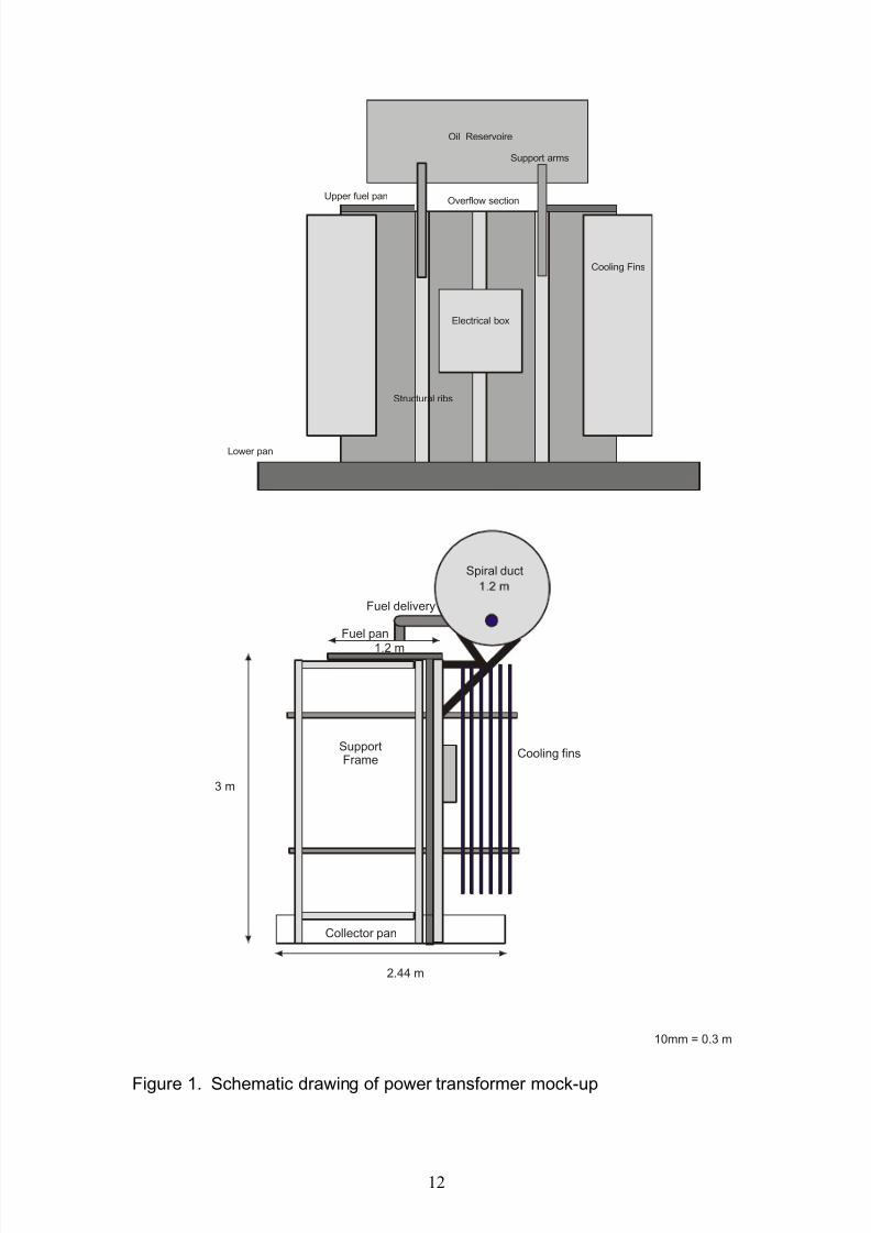
A mock-up power transformer was constructed for the experimental study. The power
transformer mock-up was constructed of 20 gauge formed steel panels fastened to a tubular
steel frame 3.9 m wide by 1.2 m deep by 3 m high. This was a scale representation of an
actual power transformer at Hydro Quebec’s Berri Station in Montreal. The mock-up was
built to represent the front half of the transformer including the oil reservoir and cooling fins.
Figure 1 shows the schematic drawing of the power transformer mock-up.
The fire scenario envisioned in the power transformer fire was an explosion in the
main transformer body due to internal arcing, resulting in the blowing of a high voltage
bushing through the top of the power transformer or the rupturing of the transformer oil
reservoir leaking oil onto the top of the transformer. The oil on top of the transformer would
be involved in fire and overflowing over the side and front of the power transformer,
producing cascading fires as well as pool fires around the bottom of the transformer. This
worst case fire scenario for the power transformer was simulated in this experimental study.
Test Fuels
Tests were conducted using electrical insulating oil typically used in power
transformers. The electrical insulating oil used in the tests was Voltesso 35, which was produced by Imperial Oil. Voltesso 35 has a density of 877 kg/m3 at 15ºC, and its flash point
is 150ºC. The normal operating temperature of the insulating oil in the power transformer is
75ºC. Therefore, during the experiments, the electrical insulating oil was pre-heated to
approximately 75ºC before it was ignited for the test.
Suppression Systems
A CAF distribution system was developed for the power transformer protection.
Several CAF configurations were studied to determine the most efficient way to distribute
foam around the vertical and horizontal obstacles of the power transformer. The final CAF
system selected for this project incorporated two types of nozzles; Large Flow Gear DrivenRotary (GDR) Nozzle and Small Flow Turbine Action Rotary (TAR) Nozzle. The TAR
8/10/2019 Article Kim 2009 Suppression in Electrical Facilities
http://slidepdf.com/reader/full/article-kim-2009-suppression-in-electrical-facilities 11/15
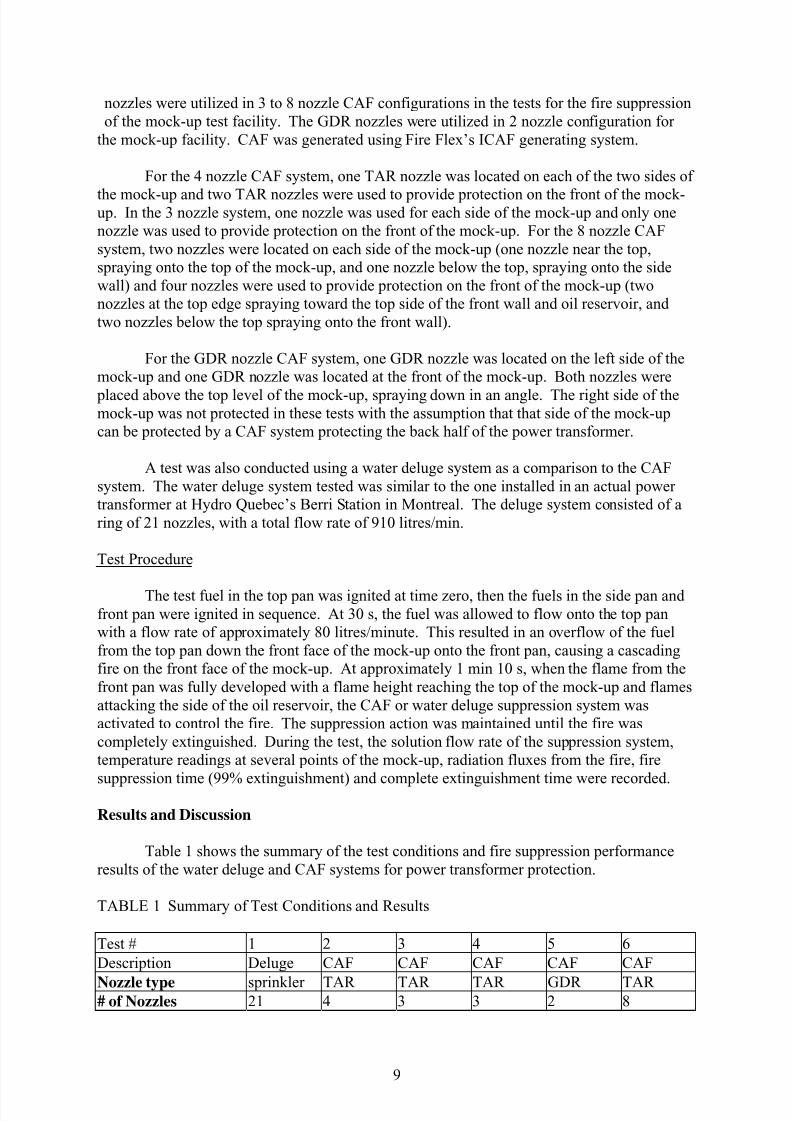
nozzles were utilized in 3 to 8 nozzle CAF configurations in the tests for the fire suppression
of the mock-up test facility. The GDR nozzles were utilized in 2 nozzle configuration for
the mock-up facility. CAF was generated using Fire Flex’s ICAF generating system.
For the 4 nozzle CAF system, one TAR nozzle was located on each of the two sides of
the mock-up and two TAR nozzles were used to provide protection on the front of the mock-up. In the 3 nozzle system, one nozzle was used for each side of the mock-up and only one
nozzle was used to provide protection on the front of the mock-up. For the 8 nozzle CAF
system, two nozzles were located on each side of the mock-up (one nozzle near the top,
spraying onto the top of the mock-up, and one nozzle below the top, spraying onto the side
wall) and four nozzles were used to provide protection on the front of the mock-up (two
nozzles at the top edge spraying toward the top side of the front wall and oil reservoir, and
two nozzles below the top spraying onto the front wall).
For the GDR nozzle CAF system, one GDR nozzle was located on the left side of the
mock-up and one GDR nozzle was located at the front of the mock-up. Both nozzles were
placed above the top level of the mock-up, spraying down in an angle. The right side of themock-up was not protected in these tests with the assumption that that side of the mock-up
can be protected by a CAF system protecting the back half of the power transformer.
A test was also conducted using a water deluge system as a comparison to the CAF
system. The water deluge system tested was similar to the one installed in an actual power
transformer at Hydro Quebec’s Berri Station in Montreal. The deluge system consisted of a
ring of 21 nozzles, with a total flow rate of 910 litres/min.
Test Procedure
The test fuel in the top pan was ignited at time zero, then the fuels in the side pan and
front pan were ignited in sequence. At 30 s, the fuel was allowed to flow onto the top pan
with a flow rate of approximately 80 litres/minute. This resulted in an overflow of the fuel
from the top pan down the front face of the mock-up onto the front pan, causing a cascading
fire on the front face of the mock-up. At approximately 1 min 10 s, when the flame from the
front pan was fully developed with a flame height reaching the top of the mock-up and flames
attacking the side of the oil reservoir, the CAF or water deluge suppression system was
activated to control the fire. The suppression action was maintained until the fire was
completely extinguished. During the test, the solution flow rate of the suppression system,
temperature readings at several points of the mock-up, radiation fluxes from the fire, fire
suppression time (99% extinguishment) and complete extinguishment time were recorded.
Results and Discussion
Table 1 shows the summary of the test conditions and fire suppression performance
results of the water deluge and CAF systems for power transformer protection.
TABLE 1 Summary of Test Conditions and Results
Test # 1 2 3 4 5 6
Description Deluge CAF CAF CAF CAF CAF
Nozzle type sprinkler TAR TAR TAR GDR TAR# of Nozzles 21 4 3 3 2 8
8/10/2019 Article Kim 2009 Suppression in Electrical Facilities
http://slidepdf.com/reader/full/article-kim-2009-suppression-in-electrical-facilities 12/15
Foam Type none Class A Class A Class B Class B Class B
Foam Concent. (%) none 1 1 2 2 2
Flow Rate (L/min) 910 88 66 66 160 160
Pre-heat (ºC) 75 76.5 76 77 75 75
Pre-burn time
(min:s)1:20 1:21 1:27 2:26 1:25 1:15
Application time
to suppress (min:s)2:05 1:09 2:16 1:21 1:33 1:13
Application time
to extinguish (min:s)3:53 1:24* 4:02 2:54 1:58 1:29
* pan on the side did not receive foam and was left burning
In Test #1, the water deluge system had 21 spray nozzles, and had total flow rate of
910 L/min. The water deluge system took 2 min 5 s to control (99% extinguishment, obtainedfrom heat flux meter data; heat flux value is 1% of the peak heat flux value) the fire,
eventually extinguishing it completely in 3 min 53 s. This fire suppression performance of
the water deluge system will be the basis of comparison for all the CAF systems tested in this
study.
In Test #2, 4 TAR nozzles were used in the CAF system. Total flow rate was 88
L/min, and Class A foam concentrate was used at 1%. The CAF system controlled the fire in
1 min 9 s and extinguished most of the fire, except one small pan on the side, in 1 min 24 s.
The foam distribution was not ideal, and the small side pan did not receive proper foam
distribution density and was left burning. In subsequent tests, the side nozzle of the TAR
CAF system was adjusted to improve its foam distribution.
In Test #3, 3 TAR nozzles were used in the CAF system, with the angle of the side
nozzle adjusted to improve the foam distribution. The total flow rate was 66 L/min. The
CAF system controlled the fire in 2 min 16 s and extinguished the fire in 4 min 2 s. The test
showed similar fire suppression performances by the CAF system with 3 TAR nozzles (test
#3) and the water deluge system (Test #1), however, the CAF system used less than 8% of the
water flow rate of the water deluge system.
Test #4 was similar to Test #3, except Class B foam concentrate was used instead of
Class A. Also, in Test #4, the pre-burn time was extended to 2 min 26 s, which made the fireto grow bigger and produced a much more challenging fire scenario for the suppression
system. Even with such a large fire, a 3 TAR nozzle CAF system, using 2% Class B foam
concentrate, extinguished the transformer fire in 2 min 54 s.
Test #5 used a 2 GDR nozzle CAF system. The CAF system using 2% Class B foam
concentrate controlled the fire in 1 min 33 s and extinguished it in 1 min 58 s.
In Test #6, an 8 TAR nozzle CAF system was used. The CAF system using 2% Class
B foam concentrate controlled the fire in 1 min 13 s and extinguished it in 1 min 29 s.
Summary
8/10/2019 Article Kim 2009 Suppression in Electrical Facilities
http://slidepdf.com/reader/full/article-kim-2009-suppression-in-electrical-facilities 13/15
The test results showed that the CAF system, either with 2 large GDR nozzles or with
3 or 4 small TAR nozzles, performed much better than the water deluge system with 21
sprinkler heads. The CAF system with 3 TAR nozzles using 1% Class A foam concentrate
extinguished the test fire in 4 min 2 s, which is almost the same as the results of the water
deluge system. However, the 3 TAR CAF system used less than 8% of the total water flow
rate of the water deluge system.
The CAF system with 2 GDR nozzles using 2% Class B foam concentrate
extinguished the test fire in 1 min 58 s, which is almost one half of the extinguishment time of
the water deluge system. And, the water usage was less than 18% of the total flow rate of the
water deluge system. The CAF system with 8 TAR nozzles using 2% Class B foam
concentrate extinguished the test fire in 1 min 29 s, with far less water requirement than the
water deluge system.
The study shows that a CAF system can provide the required fire protection for power
transformers, more effectively with much less water requirement, compared to a traditional
water deluge system.
8/10/2019 Article Kim 2009 Suppression in Electrical Facilities
http://slidepdf.com/reader/full/article-kim-2009-suppression-in-electrical-facilities 14/15
Cooling Fins
Structural ribs
Oil Reservoire
Support arms
Electrical box
Upper fuel pan
Lower pan
Overflow section
Spiral duct
Cooling finsSupportFrame
Fuel delivery
Fuel pan
Collector pan
3 m
1.2 m
2.44 m
Side view Transformer SetupScale 10mm = 0.3 m
Figure 1. Schematic drawing of power transformer mock-up
8/10/2019 Article Kim 2009 Suppression in Electrical Facilities
http://slidepdf.com/reader/full/article-kim-2009-suppression-in-electrical-facilities 15/15
CONCLUSION
There is a potential for a very large fire or explosion when using electrical equipment in
areas where flammable gases could accumulate or in room containing power transformers.
NRC has carried out projects using several newly-developed fire suppression technologies to
provide protection in an environment with an explosive atmosphere or to provide suppression ofa large fire involving electrical equipment, such as power transformers.
In one project, the explosion suppression effectiveness of hybrid gas generators in providing safety to occupants in a compartment against a deflagration type explosion was
evaluated. Several aspects of the systems, such as toxicity issues, and the effect of additives on
the suppression performance, were also studied.
In another project, the effectiveness of a newly developed compressed-air-foam (CAF)
system was evaluated for power transformer applications. The performance of the CAF system
was compared to that of sprinkler system, which is the current NFPA (National Fire Protection
Association) fire protection requirement for protecting power transformers.
In both projects, the fire suppression systems used in the projects (hybrid gas generatorwith liquid halocarbon agents for the explosion protection and CAF system for power
transformer protection), provided adequate protection for both the explosion protection and
suppression of large fires involving power transformers.
13


![Turbine suppression[2]](https://img.pdfslide.net/doc/110x75/546d3cafb4af9f662c8b53ba/turbine-suppression2.jpg)