Embed Size (px)
Citation preview
English-1© 2011 Midmark Corp. | 60 Vista Drive Versailles, OH 45380 USA | 1.800.643.6275 | 1.937.526.3662 | www.midmark.com
TP20
1 R
ev. A
Artizan® Expressions Streamline-Center™ Installation Applies to Models:SC144-200SC120-200SC96-200
Special Tools:None
Language of origin: English
003-2640-00 Rev. AB5 (3/2/22)
Equipment Alert Inspect all components for shipping damages. A concealed damage report must be filed with the carrier (by the person receiving the goods) within 15 days of delivery.
Note:All wiring, including disconnect, and plumbing must be installed by a licensed electrician or plumbing contractor following applicable local, city, and national codes.
Note:Cabinet hardware, configuration, and options may vary. General cabinet hardware, configuration, and options shown for assembly example purposes only.
Style G
English-2© 2011 Midmark Corp. | 60 Vista Drive Versailles, OH 45380 USA | 1.800.643.6275 | 1.937.526.3662 | www.midmark.com
TP20
1 R
ev. A
Equipment Alert Indicates a potentially hazardous situation which could result in equipment damage if not avoided.
Caution Indicates a potentially hazardous situation which may result in minor or moderate injury if not avoided. It may also be used to alert against unsafe practices
WARNING Indicates a potentially hazardous situation which could result in serious injury if not avoided.
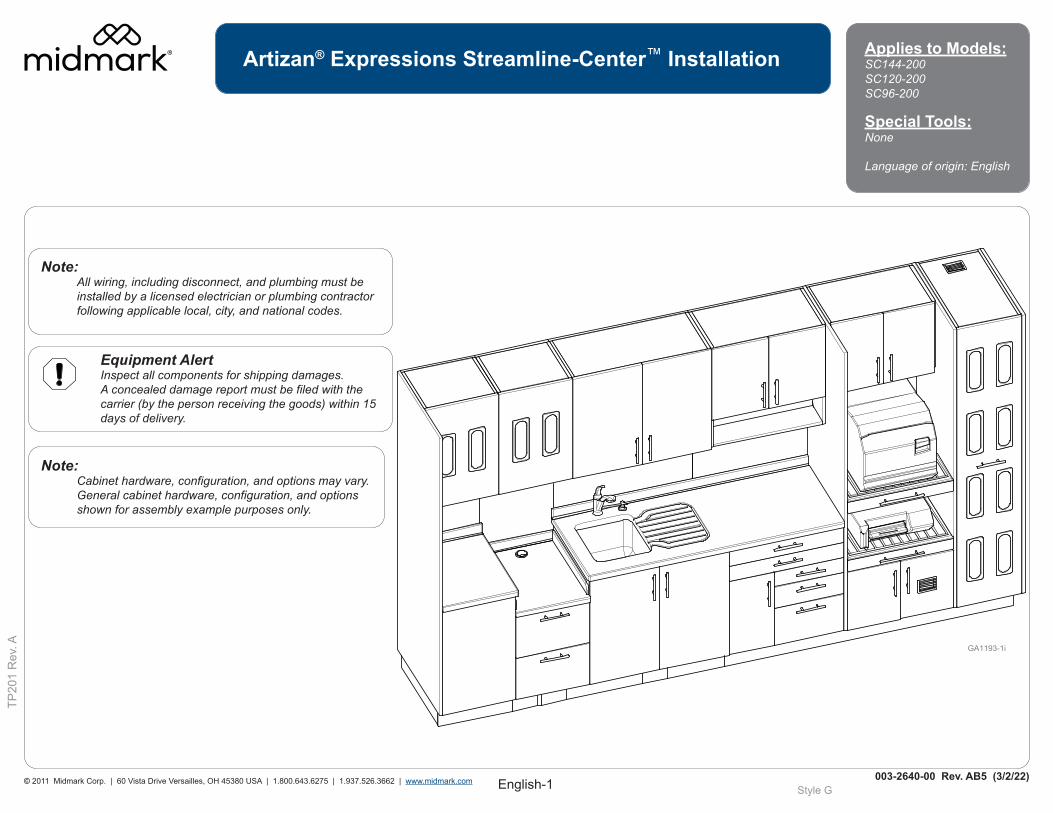
Important Information and SymbolsThese symbols may appear on your equipment and / or in the manuals.
Note:Amplifies a procedure, practice or condition.
Disposal of Equipment / Consumable GoodsAt the end of this products life, the unit, accessories and other consumable goods may be contaminated from normal use. Consult local codes and ordinates for proper disposal of this equipment and other consumables.
Pressure Limits
Humidity Limit
100 F
38 C
41 F
5 C
Temperature Limit
Type B Applied Part
Protective Earth Ground
No StackingCorrugated Recycle
Fragile
Keep Dry
AC (Alternating Current)
Proper Shipping Orientation
Consult User Guide
Transportation / Storage / Operating ConditionsTransportation / Storage Temperature Range: ..0°F to 140°F (-18°C to 60°C) Relative Humidity:...............................................10% to 90% (Non-Condensing) Atmospheric Pressure:.......................................7.2 PSI to 15.3 PSI (50 kPa to 106 kPa) Operating Temperature Range...........................59°F to 95°F (15°C to 35°C)
~
Intended UseThe Artizan® Expressions line of cabinetry is intended for use by the professional dental practitioners as supporting products in their practice providing adequate storage and technology integration for typical operatory products and equipment while still retaining an aesthetic appeal. The cabinetry should be designed to address the needs that the dental practitioners have when working in the operatory.
Contact Information:Midmark Corporation115 G.L. Comer RoadGlasgow, Kentucky 42141 Phone: 1-800-643-6275 ext. 88015Fax: (270)-651-1732
English-3© 2011 Midmark Corp. | 60 Vista Drive Versailles, OH 45380 USA | 1.800.643.6275 | 1.937.526.3662 | www.midmark.com
TP20
1 R
ev. A
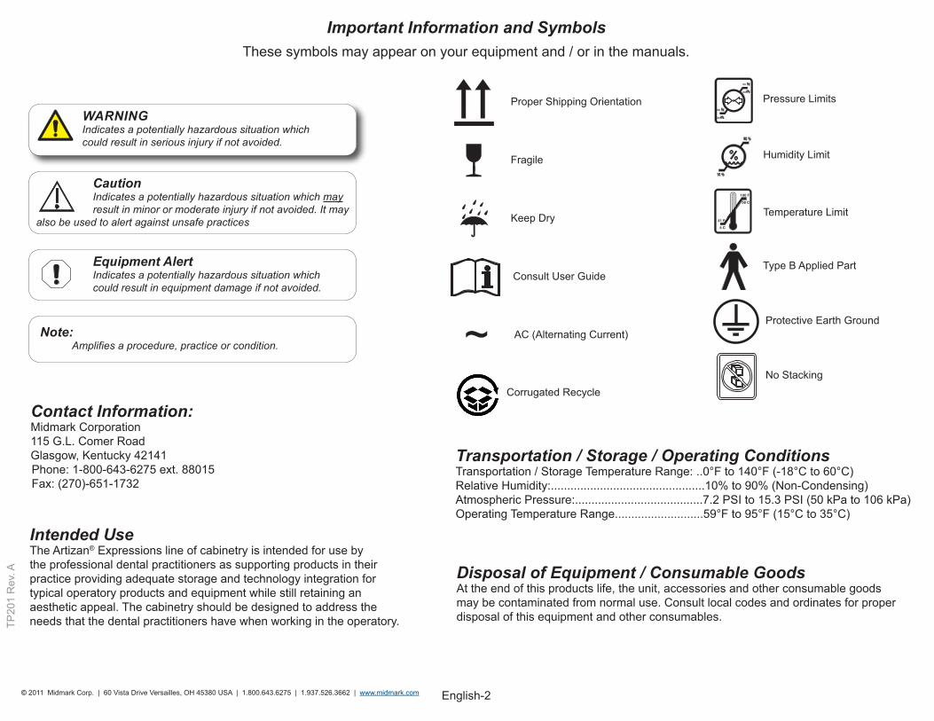
1/4-20 x 5/8” Hex Head
1/4-20 x 1-14” Flat Head Phillips
Male Panel-Stud Connector
Female Panel Connector Mirror Mount
Bumper
Connector Housing (without flange rim)
Spreading Bolt (8MM Drill Hole) Locking Shelf
Support
Glass Shelf Support Shelf Support
5/16 x 3” Hex Head Lag Bolt
6 x 1-5/8” Drywall Screw
6 x 1” Drywall Screw
M6 Connecting Bolt
3/8” x 3” LG Floor Anchor
#8 x 2-1/2” Flat Head Phillips
#8 x 3/4” Pan Head Phillips
#10-24 x 3/8” Pan Head Phillips
M6 x 14 MM LG EURO w/ Shoulder Screw
1” Cap Cover
Hardware
English-4© 2011 Midmark Corp. | 60 Vista Drive Versailles, OH 45380 USA | 1.800.643.6275 | 1.937.526.3662 | www.midmark.com
TP20
1 R
ev. A
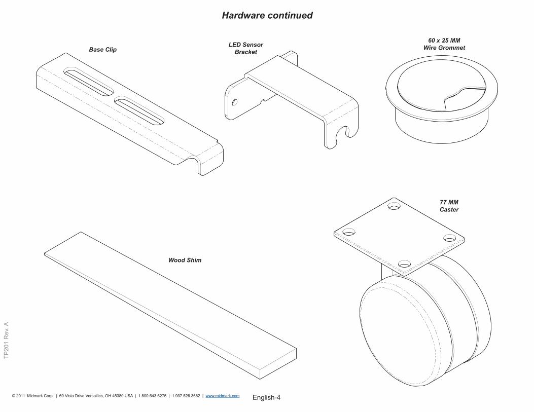
Base ClipLED Sensor
Bracket
Wood Shim
77 MM Caster
60 x 25 MM Wire Grommet
Hardware continued
English-5© 2011 Midmark Corp. | 60 Vista Drive Versailles, OH 45380 USA | 1.800.643.6275 | 1.937.526.3662 | www.midmark.com
TP20
1 R
ev. A
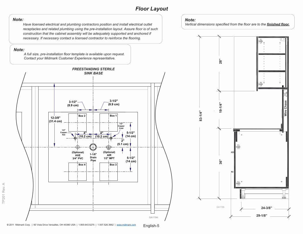
Note:A full size, pre-installation floor template is available upon request. Contact your Midmark Customer Experience representative.
Note:Have licensed electrical and plumbing contractors position and install electrical outlet receptacles and related plumbing using the pre-installation layout. Assure floor is of such construction that the cabinet assembly will be adequately supported and anchored if necessary. If necessary contact a licensed contractor to reinforce the flooring.
83-1
/4”
Wire
Cha
se
19-1
/4”
28”
36”
24-3/8”
29-1/8”
GA1195
Note:Vertical dimensions specified from the floor are to the finished floor.
FREESTANDING STERILESINK BASE
Floor Layout
English-6© 2011 Midmark Corp. | 60 Vista Drive Versailles, OH 45380 USA | 1.800.643.6275 | 1.937.526.3662 | www.midmark.com
TP20
1 R
ev. A
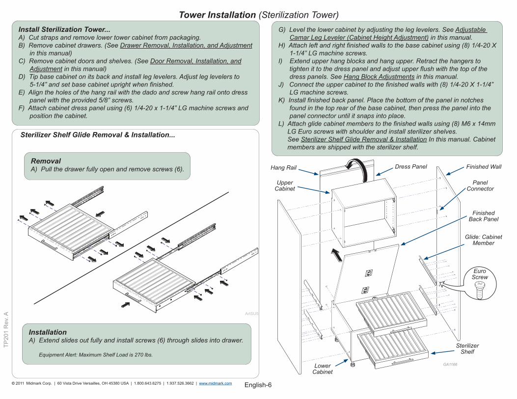
Tower Installation (Sterilization Tower)Install Sterilization Tower...A) Cut straps and remove lower tower cabinet from packaging. B) Remove cabinet drawers. (See Drawer Removal, Installation, and Adjustment in this manual) C) Remove cabinet doors and shelves. (See Door Removal, Installation, and Adjustment in this manual) D) Tip base cabinet on its back and install leg levelers. Adjust leg levelers to 5-1/4” and set base cabinet upright when finished. E) Align the holes of the hang rail with the dado and screw hang rail onto dress panel with the provided 5/8” screws. F) Attach cabinet dress panel using (6) 1/4-20 x 1-1/4” LG machine screws and position the cabinet.
G) Level the lower cabinet by adjusting the leg levelers. See Adjustable Camar Leg Leveler (Cabinet Height Adjustment) in this manual. H) Attach left and right finished walls to the base cabinet using (8) 1/4-20 X 1-1/4” LG machine screws. I) Extend upper hang blocks and hang upper. Retract the hangers to tighten it to the dress panel and adjust upper flush with the top of the dress panels. See Hang Block Adjustments in this manual. J) Connect the upper cabinet to the finished walls with (8) 1/4-20 X 1-1/4” LG machine screws. K) Install finished back panel. Place the bottom of the panel in notches found in the top rear of the base cabinet, then press the panel into the panel connector until it snaps into place. L) Attach glide cabinet members to the finished walls using (8) M6 x 14mm LG Euro screws with shoulder and install sterilizer shelves. See Sterilizer Shelf Glide Removal & Installation In this manual. Cabinet members are shipped with the sterilizer shelf.
GA1166
EuroScrew
Hang Rail Dress Panel Finished Wall
Panel Connector
Upper Cabinet
Finished Back Panel
Glide: Cabinet Member
Lower Cabinet
Sterilizer Shelf
Sterilizer Shelf Glide Removal & Installation...
RemovalA) Pull the drawer fully open and remove screws (6).
InstallationA) Extend slides out fully and install screws (6) through slides into drawer.
Equipment Alert: Maximum Shelf Load is 270 lbs.
English-7© 2011 Midmark Corp. | 60 Vista Drive Versailles, OH 45380 USA | 1.800.643.6275 | 1.937.526.3662 | www.midmark.com
TP20
1 R
ev. A
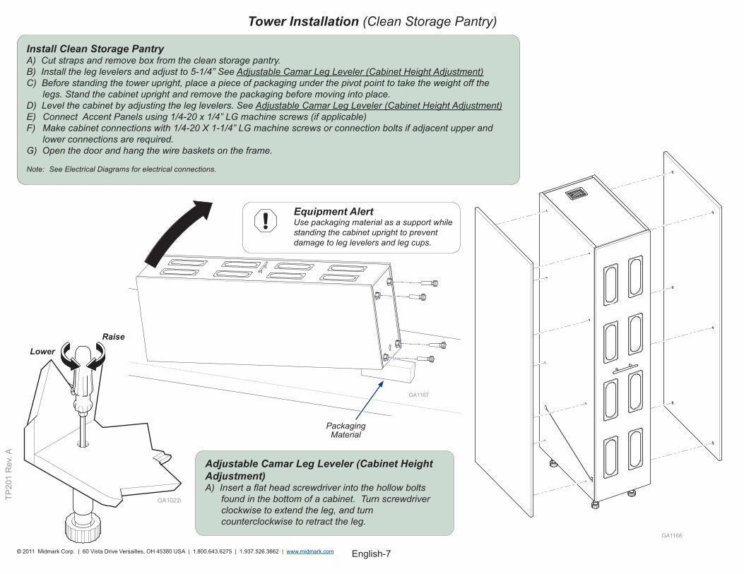
Tower Installation (Clean Storage Pantry)
Adjustable Camar Leg Leveler (Cabinet Height Adjustment)A) Insert a flat head screwdriver into the hollow bolts found in the bottom of a cabinet. Turn screwdriver clockwise to extend the leg, and turn counterclockwise to retract the leg.
GA1167
GA1168
Equipment Alert Use packaging material as a support while standing the cabinet upright to prevent damage to leg levelers and leg cups.
Packaging Material
RaiseLower
Install Clean Storage PantryA) Cut straps and remove box from the clean storage pantry. B) Install the leg levelers and adjust to 5-1/4” See Adjustable Camar Leg Leveler (Cabinet Height Adjustment) C) Before standing the tower upright, place a piece of packaging under the pivot point to take the weight off the legs. Stand the cabinet upright and remove the packaging before moving into place. D) Level the cabinet by adjusting the leg levelers. See Adjustable Camar Leg Leveler (Cabinet Height Adjustment) E) Connect Accent Panels using 1/4-20 x 1/4” LG machine screws (if applicable) F) Make cabinet connections with 1/4-20 X 1-1/4” LG machine screws or connection bolts if adjacent upper and lower connections are required. G) Open the door and hang the wire baskets on the frame.
Note: See Electrical Diagrams for electrical connections.
English-8© 2011 Midmark Corp. | 60 Vista Drive Versailles, OH 45380 USA | 1.800.643.6275 | 1.937.526.3662 | www.midmark.com
TP20
1 R
ev. A
Tower Installation (Tray Storage Tower)
GA1170
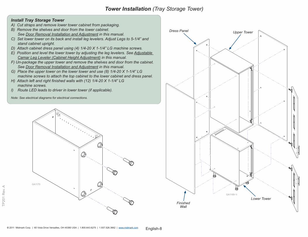
Install Tray Storage TowerA) Cut straps and remove lower tower cabinet from packaging. B) Remove the shelves and door from the lower cabinet. See Door Removal Installation and Adjustment in this manual. C) Set lower tower on its back and install leg levelers. Adjust Legs to 5-1/4” and stand cabinet upright. D) Attach cabinet dress panel using (4) 1/4-20 X 1-1/4” LG machine screws. E) Position and level the lower tower by adjusting the leg levelers. See Adjustable Camar Leg Leveler (Cabinet Height Adjustment) in this manual. F) Un-package the upper tower and remove the shelves and door from the cabinet. See Door Removal Installation and Adjustment in this manual. G) Place the upper tower on the lower tower and use (8) 1/4-20 X 1-1/4” LG machine screws to attach the top cabinet to the lower cabinet and dress panel. H) Attach left and right finished walls with (12) 1/4-20 X 1-1/4” LG machine screws. I) Route LED leads to driver in lower tower (if applicable).
Note: See electrical diagrams for electrical connections.
GA1169-1i
Lower Tower
Upper TowerDress Panel
Finished Wall
English-9© 2011 Midmark Corp. | 60 Vista Drive Versailles, OH 45380 USA | 1.800.643.6275 | 1.937.526.3662 | www.midmark.com
TP20
1 R
ev. A
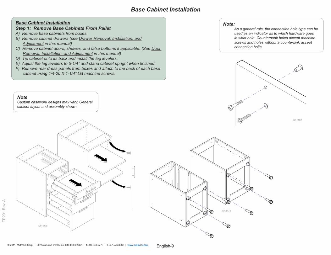
Base Cabinet Installation Step 1: Remove Base Cabinets From PalletA) Remove base cabinets from boxes. B) Remove cabinet drawers (see Drawer Removal, Installation, and Adjustment in this manual) C) Remove cabinet doors, shelves, and false bottoms if applicable. (See Door Removal, Installation, and Adjustment in this manual) D) Tip cabinet onto its back and install the leg levelers. E) Adjust the leg levelers to 5-1/4” and stand cabinet upright when finished. F) Remove rear dress panels from boxes and attach to the back of each base cabinet using 1/4-20 X 1-1/4” LG machine screws.
Base Cabinet Installation
GA1175
NoteCustom casework designs may vary. General cabinet layout and assembly shown.
Note:As a general rule, the connection hole type can be used as an indicator as to which hardware goes in what hole. Countersunk holes accept machine screws and holes without a countersink accept connection bolts.
GA1192
GA1250i
English-10© 2011 Midmark Corp. | 60 Vista Drive Versailles, OH 45380 USA | 1.800.643.6275 | 1.937.526.3662 | www.midmark.com
TP20
1 R
ev. A
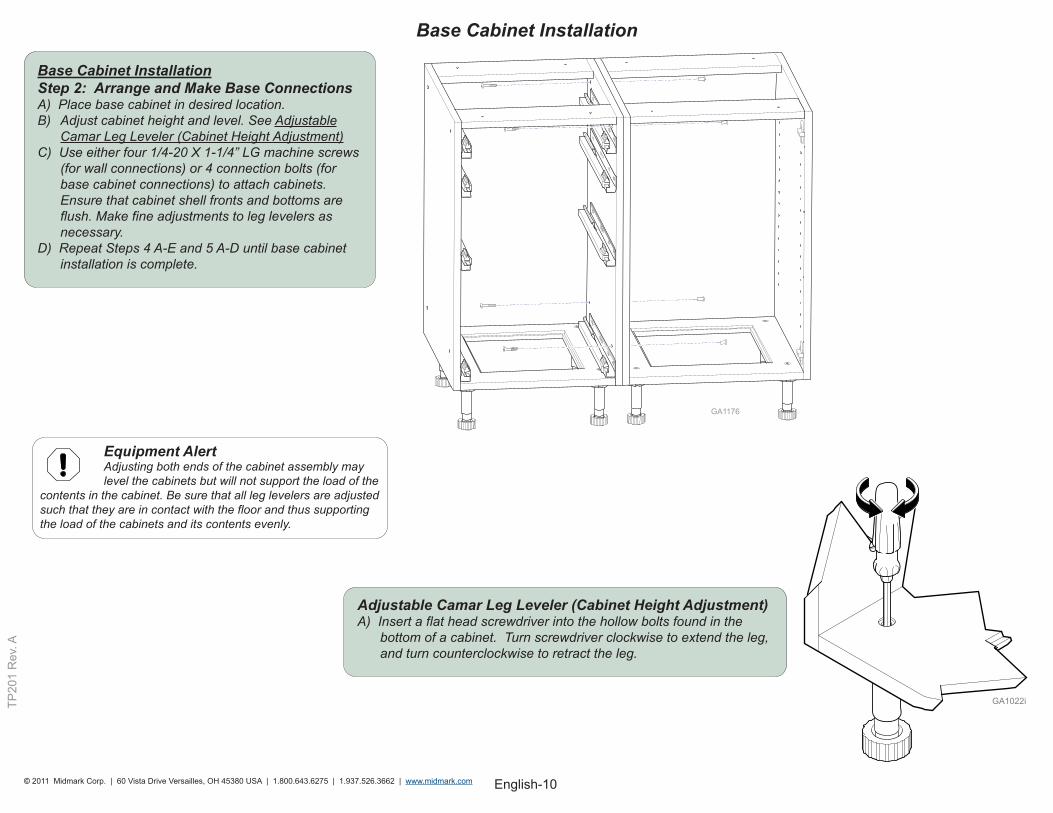
Base Cabinet Installation Step 2: Arrange and Make Base ConnectionsA) Place base cabinet in desired location. B) Adjust cabinet height and level. See Adjustable Camar Leg Leveler (Cabinet Height Adjustment) C) Use either four 1/4-20 X 1-1/4” LG machine screws (for wall connections) or 4 connection bolts (for base cabinet connections) to attach cabinets. Ensure that cabinet shell fronts and bottoms are flush. Make fine adjustments to leg levelers as necessary. D) Repeat Steps 4 A-E and 5 A-D until base cabinet installation is complete.
Base Cabinet Installation
Equipment Alert Adjusting both ends of the cabinet assembly may level the cabinets but will not support the load of the contents in the cabinet. Be sure that all leg levelers are adjusted such that they are in contact with the floor and thus supporting the load of the cabinets and its contents evenly.
GA1176
Adjustable Camar Leg Leveler (Cabinet Height Adjustment)A) Insert a flat head screwdriver into the hollow bolts found in the bottom of a cabinet. Turn screwdriver clockwise to extend the leg, and turn counterclockwise to retract the leg.
English-11© 2011 Midmark Corp. | 60 Vista Drive Versailles, OH 45380 USA | 1.800.643.6275 | 1.937.526.3662 | www.midmark.com
TP20
1 R
ev. A
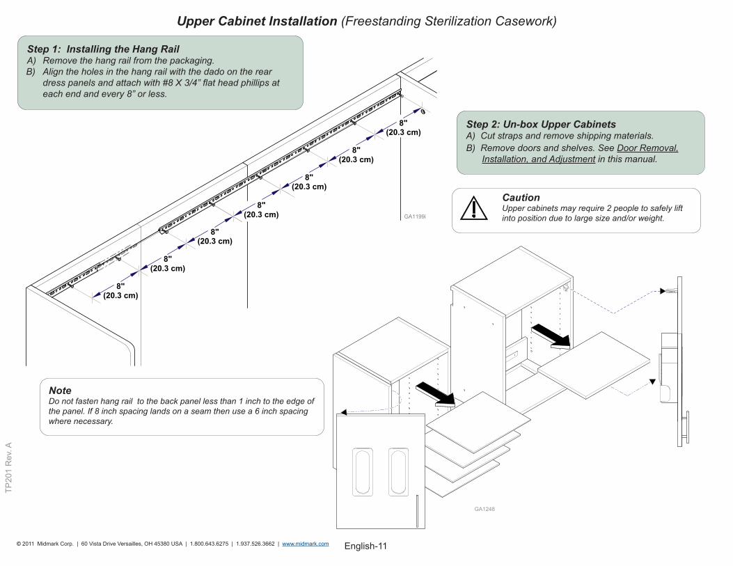
Step 2: Un-box Upper CabinetsA) Cut straps and remove shipping materials. B) Remove doors and shelves. See Door Removal,
Installation, and Adjustment in this manual.
Caution Upper cabinets may require 2 people to safely lift into position due to large size and/or weight.
Upper Cabinet Installation (Freestanding Sterilization Casework)
NoteDo not fasten hang rail to the back panel less than 1 inch to the edge of the panel. If 8 inch spacing lands on a seam then use a 6 inch spacing where necessary.
GA1248
Step 1: Installing the Hang RailA) Remove the hang rail from the packaging. B) Align the holes in the hang rail with the dado on the rear dress panels and attach with #8 X 3/4” flat head phillips at each end and every 8” or less.
English-12© 2011 Midmark Corp. | 60 Vista Drive Versailles, OH 45380 USA | 1.800.643.6275 | 1.937.526.3662 | www.midmark.com
TP20
1 R
ev. A
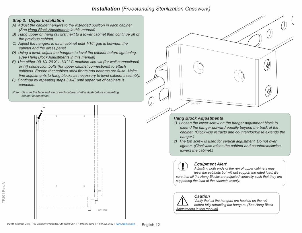
Installation (Freestanding Sterilization Casework)
Caution Verify that all the hangers are hooked on the rail before fully retracting the hangers. (See Hang Block Adjustments in this manual)
Equipment Alert Adjusting both ends of the run of upper cabinets may level the cabinets but will not support the rated load. Be sure that all the Hang Blocks are adjusted vertically such that they are supporting the load of the cabinets evenly.
Hang Block Adjustments 1) Loosen the lower screw on the hanger adjustment block to
extend the hanger outward equally beyond the back of the cabinet. (Clockwise retracts and counterclockwise extends the hanger.)
2) The top screw is used for vertical adjustment. Do not overtighten. (Clockwise raises the cabinet and counterclockwise lowers the cabinet.)
Step 3: Upper InstallationA) Adjust the cabinet hangers to the extended position in each cabinet. (See Hang Block Adjustments in this manual)B) Hang upper on hang rail first next to a tower cabinet then continue off of the previous cabinet. C) Adjust the hangers in each cabinet until 1/16” gap is between the cabinet and the dress panel.D) Using a level, adjust the hangers to level the cabinet before tightening. (See Hang Block Adjustments in this manual) E) Use either (4) 1/4-20 X 1-1/4” LG machine screws (for wall connections) or (4) connection bolts (for upper cabinet connections) to attach cabinets. Ensure that cabinet shell fronts and bottoms are flush. Make fine adjustments to hang blocks as necessary to level cabinet assembly. F) Continue by repeating steps 3 A-E until upper run of cabinets is complete. Note: Be sure the face and top of each cabinet shell is flush before completing cabinet connections.
English-13© 2011 Midmark Corp. | 60 Vista Drive Versailles, OH 45380 USA | 1.800.643.6275 | 1.937.526.3662 | www.midmark.com
TP20
1 R
ev. A
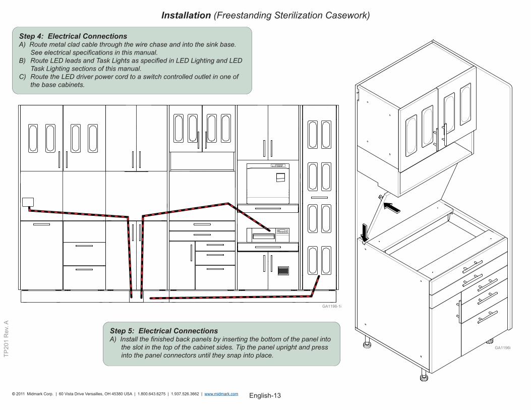
Step 4: Electrical ConnectionsA) Route metal clad cable through the wire chase and into the sink base. See electrical specifications in this manual. B) Route LED leads and Task Lights as specified in LED Lighting and LED Task Lighting sections of this manual. C) Route the LED driver power cord to a switch controlled outlet in one of the base cabinets.
Step 5: Electrical ConnectionsA) Install the finished back panels by inserting the bottom of the panel into the slot in the top of the cabinet sides. Tip the panel upright and press into the panel connectors until they snap into place.
Installation (Freestanding Sterilization Casework)
English-14© 2011 Midmark Corp. | 60 Vista Drive Versailles, OH 45380 USA | 1.800.643.6275 | 1.937.526.3662 | www.midmark.com
TP20
1 R
ev. A
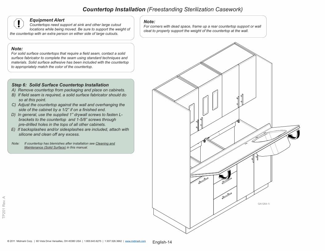
Step 6: Solid Surface Countertop InstallationA) Remove countertop from packaging and place on cabinets. B) If field seam is required, a solid surface fabricator should do so at this point. C) Adjust the countertop against the wall and overhanging the side of the cabinet by a 1/2” if on a finished end.D) In general, use the supplied 1” drywall screws to fasten L- brackets to the countertop and 1-5/8” screws through pre-drilled holes in the tops of all other cabinets. E) If backsplashes and/or sidesplashes are included, attach with silicone and clean off any excess.
Note: If countertop has blemishes after installation see Cleaning and Maintenance (Solid Surface) in this manual.
Note:For solid surface countertops that require a field seam, contact a solid surface fabricator to complete the seam using standard techniques and materials. Solid surface adhesive has been included with the countertop to appropriately match the color of the countertop.
Equipment Alert Countertops need support at sink and other large cutout locations while being moved. Be sure to support the weight of the countertop with an extra person on either side of large cutouts.
Note:For corners with dead space, frame up a rear countertop support or wall cleat to properly support the weight of the countertop at the wall.
Countertop Installation (Freestanding Sterilization Casework)
English-15© 2011 Midmark Corp. | 60 Vista Drive Versailles, OH 45380 USA | 1.800.643.6275 | 1.937.526.3662 | www.midmark.com
TP20
1 R
ev. A
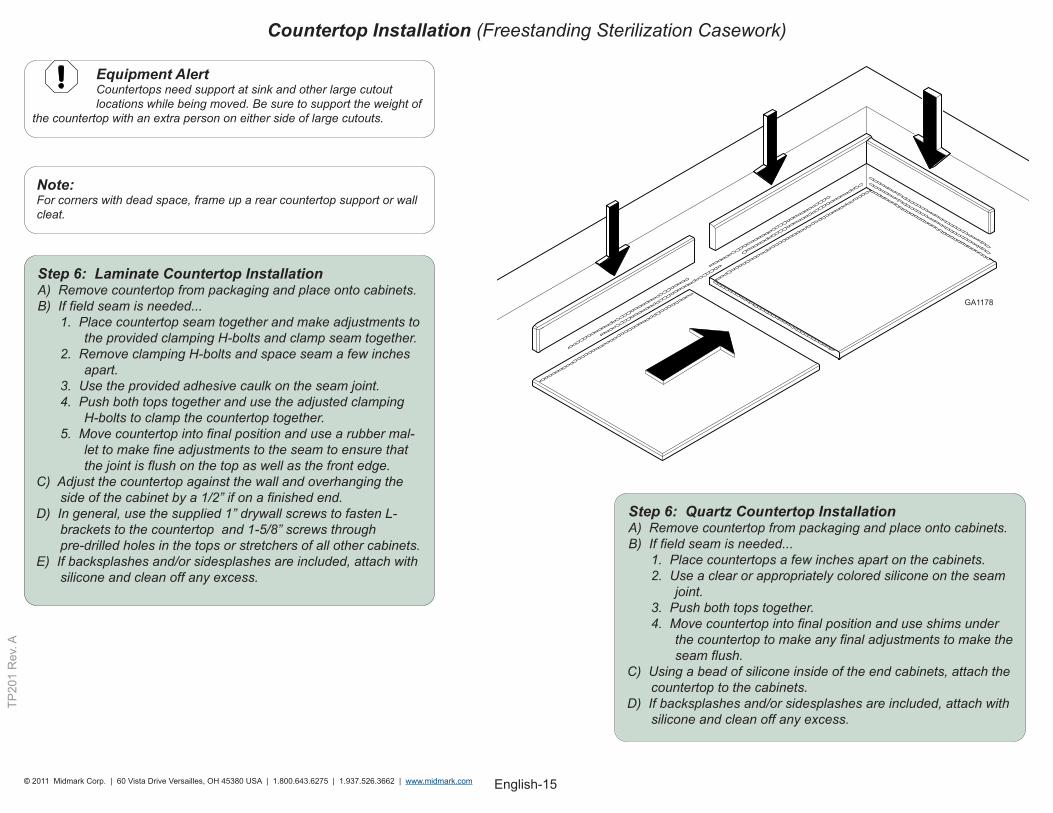
Step 6: Laminate Countertop InstallationA) Remove countertop from packaging and place onto cabinets. B) If field seam is needed...
1. Place countertop seam together and make adjustments to the provided clamping H-bolts and clamp seam together.
2. Remove clamping H-bolts and space seam a few inches apart.
3. Use the provided adhesive caulk on the seam joint.4. Push both tops together and use the adjusted clamping
H-bolts to clamp the countertop together. 5. Move countertop into final position and use a rubber mal-
let to make fine adjustments to the seam to ensure that the joint is flush on the top as well as the front edge.
C) Adjust the countertop against the wall and overhanging the side of the cabinet by a 1/2” if on a finished end. D) In general, use the supplied 1” drywall screws to fasten L- brackets to the countertop and 1-5/8” screws through pre-drilled holes in the tops or stretchers of all other cabinets. E) If backsplashes and/or sidesplashes are included, attach with silicone and clean off any excess.
Step 6: Quartz Countertop InstallationA) Remove countertop from packaging and place onto cabinets. B) If field seam is needed...
1. Place countertops a few inches apart on the cabinets.2. Use a clear or appropriately colored silicone on the seam
joint.3. Push both tops together.4. Move countertop into final position and use shims under
the countertop to make any final adjustments to make the seam flush.
C) Using a bead of silicone inside of the end cabinets, attach the countertop to the cabinets. D) If backsplashes and/or sidesplashes are included, attach with silicone and clean off any excess.
Note:For corners with dead space, frame up a rear countertop support or wall cleat.
Equipment Alert Countertops need support at sink and other large cutout locations while being moved. Be sure to support the weight of the countertop with an extra person on either side of large cutouts.
GA1178
Countertop Installation (Freestanding Sterilization Casework)
English-16© 2011 Midmark Corp. | 60 Vista Drive Versailles, OH 45380 USA | 1.800.643.6275 | 1.937.526.3662 | www.midmark.com
TP20
1 R
ev. A
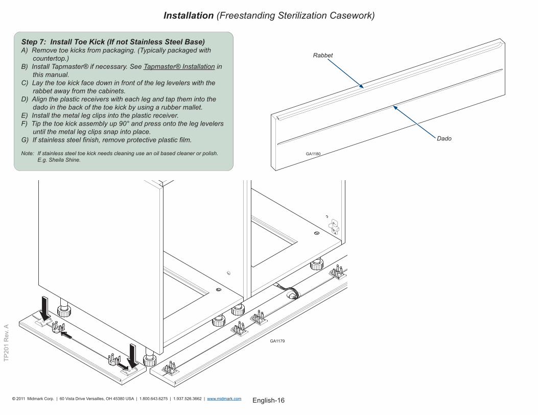
Step 7: Install Toe Kick (If not Stainless Steel Base)A) Remove toe kicks from packaging. (Typically packaged with countertop.) B) Install Tapmaster® if necessary. See Tapmaster® Installation in this manual. C) Lay the toe kick face down in front of the leg levelers with the rabbet away from the cabinets. D) Align the plastic receivers with each leg and tap them into the dado in the back of the toe kick by using a rubber mallet. E) Install the metal leg clips into the plastic receiver. F) Tip the toe kick assembly up 90° and press onto the leg levelers until the metal leg clips snap into place. G) If stainless steel finish, remove protective plastic film. Note: If stainless steel toe kick needs cleaning use an oil based cleaner or polish. E.g. Sheila Shine.
GA1180
GA1179
Rabbet
Dado
Installation (Freestanding Sterilization Casework)
English-17© 2011 Midmark Corp. | 60 Vista Drive Versailles, OH 45380 USA | 1.800.643.6275 | 1.937.526.3662 | www.midmark.com
TP20
1 R
ev. A
Tapmaster® Installation
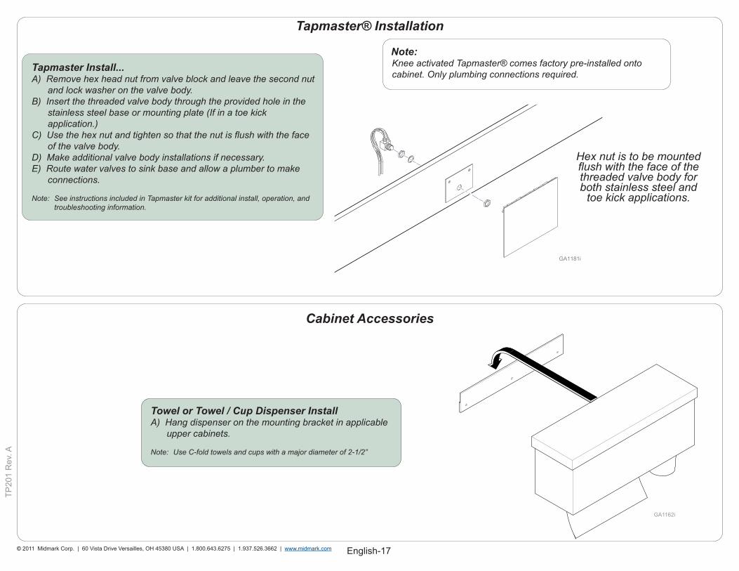
Note:Knee activated Tapmaster® comes factory pre-installed onto cabinet. Only plumbing connections required.
Tapmaster Install...A) Remove hex head nut from valve block and leave the second nut and lock washer on the valve body. B) Insert the threaded valve body through the provided hole in the stainless steel base or mounting plate (If in a toe kick application.) C) Use the hex nut and tighten so that the nut is flush with the face of the valve body. D) Make additional valve body installations if necessary. E) Route water valves to sink base and allow a plumber to make connections. Note: See instructions included in Tapmaster kit for additional install, operation, and troubleshooting information.
Hex nut is to be mounted flush with the face of the threaded valve body for both stainless steel and
toe kick applications.
Towel or Towel / Cup Dispenser InstallA) Hang dispenser on the mounting bracket in applicable upper cabinets.
Note: Use C-fold towels and cups with a major diameter of 2-1/2”
Cabinet Accessories
GA1162i
English-18© 2011 Midmark Corp. | 60 Vista Drive Versailles, OH 45380 USA | 1.800.643.6275 | 1.937.526.3662 | www.midmark.com
TP20
1 R
ev. A
LED Lighting
LED Task Lighting
LED Leads
DriverPower Cord
Switch Controlled
Outlet Snap-in Panel
Clip
Screw
Task Light
8”
Upper Cabinet Bottom Hole
Upper Cabinet
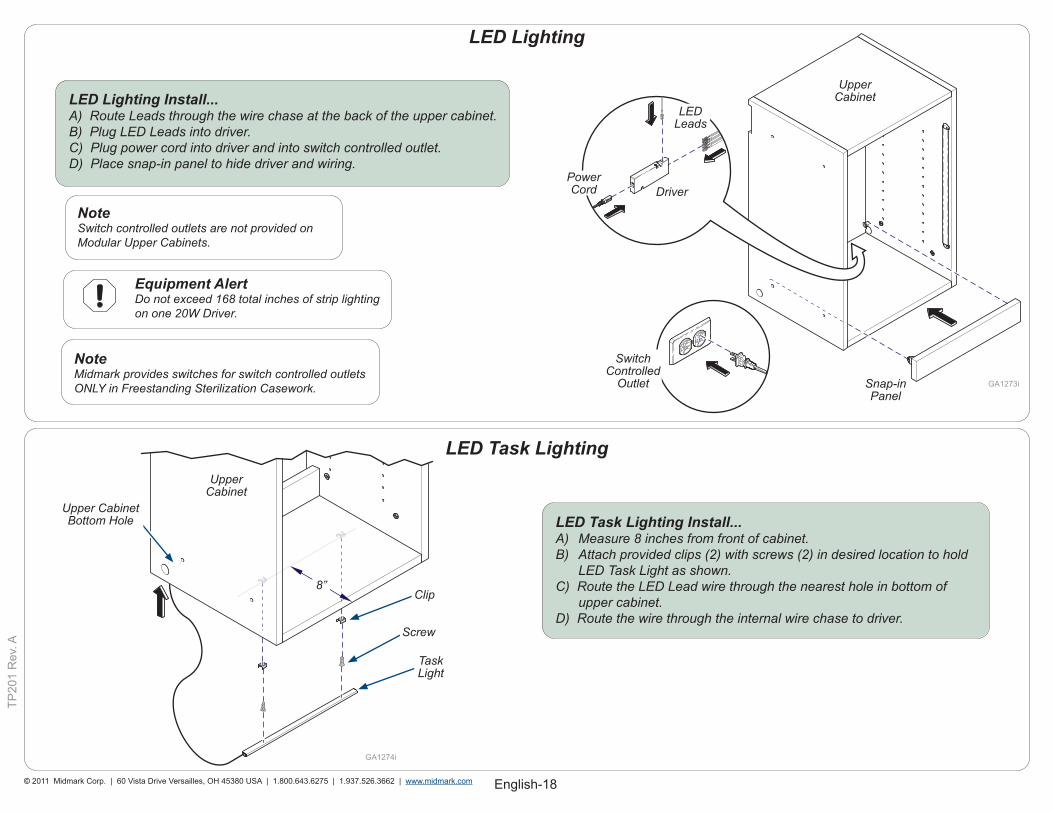
LED Task Lighting Install...A) Measure 8 inches from front of cabinet. B) Attach provided clips (2) with screws (2) in desired location to hold LED Task Light as shown. C) Route the LED Lead wire through the nearest hole in bottom of upper cabinet. D) Route the wire through the internal wire chase to driver.
Upper Cabinet
LED Lighting Install...A) Route Leads through the wire chase at the back of the upper cabinet. B) Plug LED Leads into driver. C) Plug power cord into driver and into switch controlled outlet. D) Place snap-in panel to hide driver and wiring.
Equipment Alert Do not exceed 168 total inches of strip lighting on one 20W Driver.
NoteSwitch controlled outlets are not provided on Modular Upper Cabinets.
NoteMidmark provides switches for switch controlled outlets ONLY in Freestanding Sterilization Casework.
English-19© 2011 Midmark Corp. | 60 Vista Drive Versailles, OH 45380 USA | 1.800.643.6275 | 1.937.526.3662 | www.midmark.com
TP20
1 R
ev. A
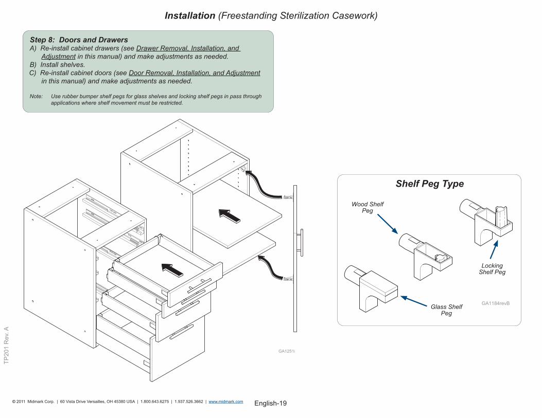
Step 8: Doors and DrawersA) Re-install cabinet drawers (see Drawer Removal, Installation, and Adjustment in this manual) and make adjustments as needed. B) Install shelves. C) Re-install cabinet doors (see Door Removal, Installation, and Adjustment in this manual) and make adjustments as needed.
Note: Use rubber bumper shelf pegs for glass shelves and locking shelf pegs in pass through applications where shelf movement must be restricted.
Shelf Peg Type
Glass Shelf Peg
Wood Shelf Peg
Locking Shelf Peg
Installation (Freestanding Sterilization Casework)
English-20© 2011 Midmark Corp. | 60 Vista Drive Versailles, OH 45380 USA | 1.800.643.6275 | 1.937.526.3662 | www.midmark.com
TP20
1 R
ev. A
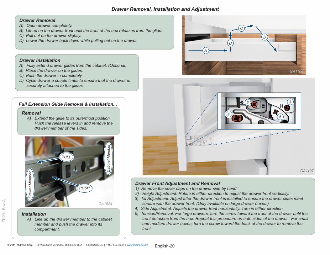
Drawer InstallationA) Fully extend drawer glides from the cabinet. (Optional)B) Place the drawer on the glides. C) Push the drawer in completely. D) Cycle drawer a couple times to ensure that the drawer is
securely attached to the glides.
Drawer RemovalA) Open drawer completely. B) Lift up on the drawer front until the front of the box releases from the glide. C) Pull out on the drawer slightly. D) Lower the drawer back down while pulling out on the drawer.
Drawer Front Adjustment and Removal1) Remove the cover caps on the drawer side by hand.2) Height Adjustment: Rotate in either direction to adjust the drawer front vertically.3) Tilt Adjustment: Adjust after the drawer front is installed to ensure the drawer sides meet
square with the drawer front. (Only available on large drawer boxes.)4) Side Adjustment: Adjusts the drawer front horizontally. Turn in either direction.5) Tension/Removal: For large drawers, turn the screw toward the front of the drawer until the
front detaches from the box. Repeat this procedure on both sides of the drawer. For small and medium drawer boxes, turn the screw toward the back of the drawer to remove the front.
Drawer Removal, Installation and Adjustment
RemovalA) Extend the glide to its outermost position. Push the release levers in and remove the
drawer member of the sides.
Full Extension Glide Removal & Installation...
InstallationA) Line up the drawer member to the cabinet
member and push the drawer into its compartment.
A
B
C
D
GA1106
GA1107
45
32
PUSH
PULL
Cab
inet
Mem
ber
Dra
wer
Mem
ber
GA1024
English-21© 2011 Midmark Corp. | 60 Vista Drive Versailles, OH 45380 USA | 1.800.643.6275 | 1.937.526.3662 | www.midmark.com
TP20
1 R
ev. A
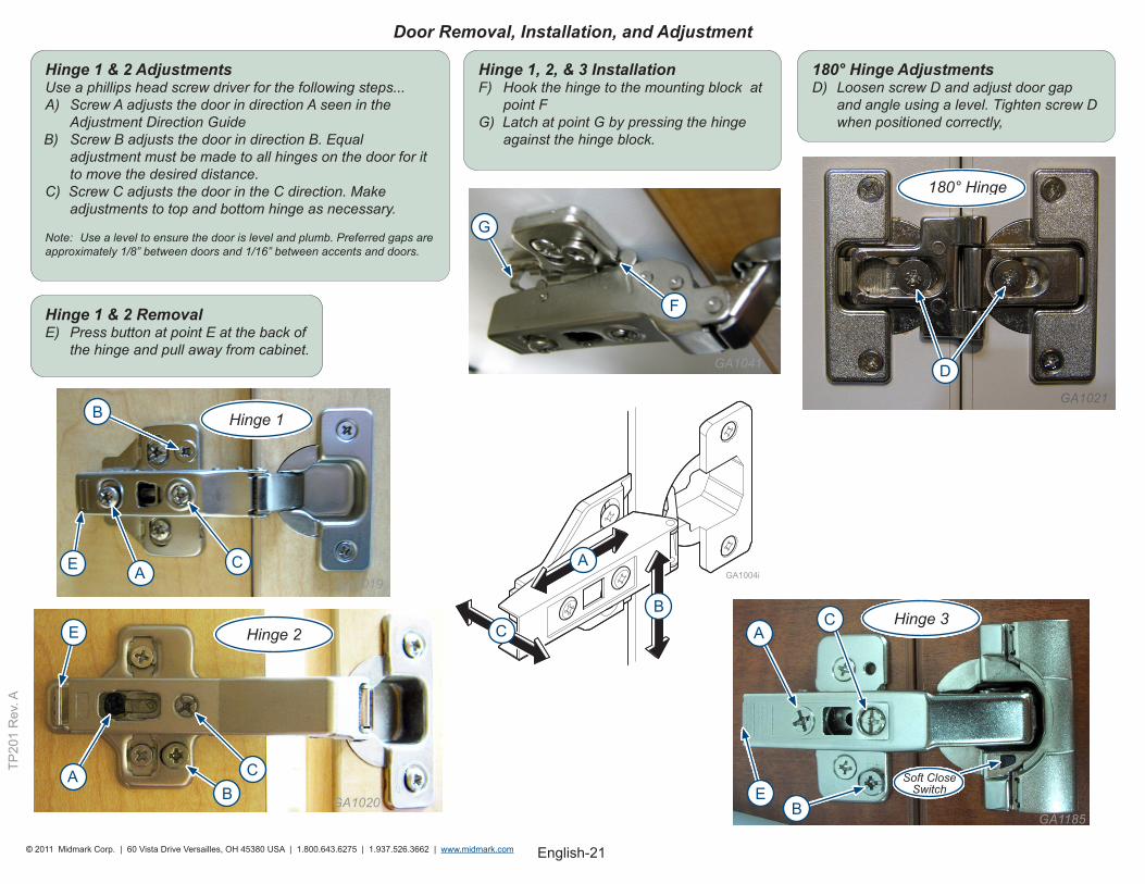
Hinge 1 & 2 AdjustmentsUse a phillips head screw driver for the following steps...A) Screw A adjusts the door in direction A seen in the
Adjustment Direction GuideB) Screw B adjusts the door in direction B. Equal adjustment must be made to all hinges on the door for it to move the desired distance.C) Screw C adjusts the door in the C direction. Make adjustments to top and bottom hinge as necessary.
Note: Use a level to ensure the door is level and plumb. Preferred gaps are approximately 1/8” between doors and 1/16” between accents and doors.
180° Hinge AdjustmentsD) Loosen screw D and adjust door gap and angle using a level. Tighten screw D when positioned correctly,
180° Hinge
Hinge 1 & 2 RemovalE) Press button at point E at the back of the hinge and pull away from cabinet.
Door Removal, Installation, and Adjustment
Hinge 1
Hinge 1, 2, & 3 InstallationF) Hook the hinge to the mounting block at point F G) Latch at point G by pressing the hinge against the hinge block.
Hinge 2Hinge 3
Soft Close Switch
E
D
C
B
A
G
F
AB
C
E
GA1019
GA1020
GA1021
A
CB
E
C
B
A
GA1185
GA1041
English-22© 2011 Midmark Corp. | 60 Vista Drive Versailles, OH 45380 USA | 1.800.643.6275 | 1.937.526.3662 | www.midmark.com
TP20
1 R
ev. A
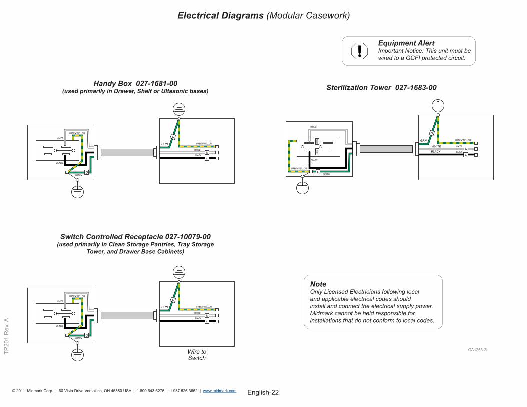
Electrical Diagrams (Modular Casework)
Sterilization Tower 027-1683-00Handy Box 027-1681-00 (used primarily in Drawer, Shelf or Ultasonic bases)
NoteOnly Licensed Electricians following local and applicable electrical codes should install and connect the electrical supply power. Midmark cannot be held responsible for installations that do not conform to local codes.
Equipment Alert Important Notice: This unit must be wired to a GCFI protected circuit.
Switch Controlled Receptacle 027-10079-00 (used primarily in Clean Storage Pantries, Tray Storage
Tower, and Drawer Base Cabinets)
Wire to Switch
English-23© 2011 Midmark Corp. | 60 Vista Drive Versailles, OH 45380 USA | 1.800.643.6275 | 1.937.526.3662 | www.midmark.com
TP20
1 R
ev. A
GRN
BLACK
WHITE WHITE
BLACK
GREEN/ YELLOW
L
N
G
RESETT
ES
T
GGREEN/ YELLOW
WHITE
BLACK
GREEN
L
NWHITE WHITE
GRN
BLACK BLACK
GREEN/ YELLOW
G
WHITE BLACK
GGREEN
GREEN/ YELLOW
GRN
BLACK
WHITE WHITE
BLACK
GREEN/ YELLOW
L
N
G
RESETT
ES
T
GGREEN/ YELLOW
WHITE
BLACK
GREEN
L
NWHITE WHITE
GRN
BLACK BLACK
GREEN/ YELLOW
G
WHITE BLACK
GGREEN
GREEN/ YELLOW
WHITE BLACK
GGREEN
GREEN/ YELLOW
L
NWHITE WHITE
GRN
BLACK BLACK
GREEN/ YELLOW
G
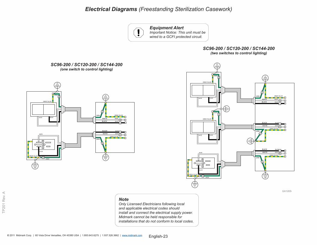
Equipment Alert Important Notice: This unit must be wired to a GCFI protected circuit.
SC96-200 / SC120-200 / SC144-200 (one switch to control lighting)
NoteOnly Licensed Electricians following local and applicable electrical codes should install and connect the electrical supply power. Midmark cannot be held responsible for installations that do not conform to local codes.
SC96-200 / SC120-200 / SC144-200 (two switches to control lighting)
Electrical Diagrams (Freestanding Sterilization Casework)
English-24© 2011 Midmark Corp. | 60 Vista Drive Versailles, OH 45380 USA | 1.800.643.6275 | 1.937.526.3662 | www.midmark.com
TP20
1 R
ev. A
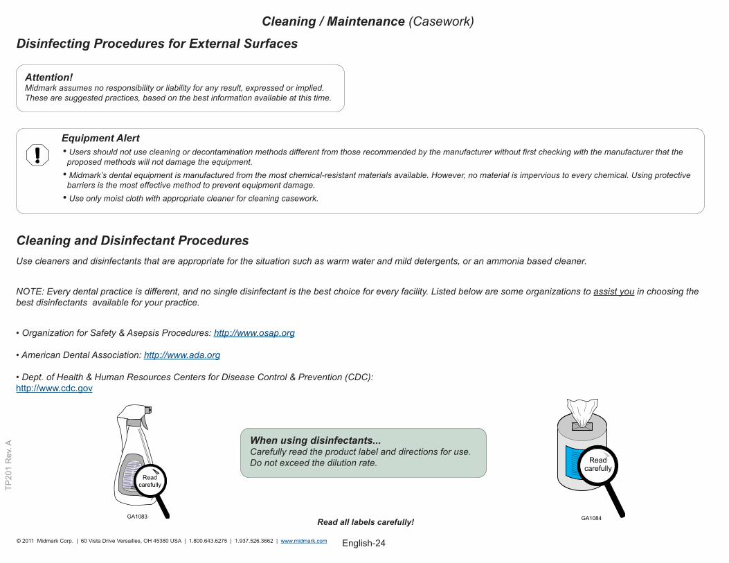
Disinfecting Procedures for External Surfaces
Attention!Midmark assumes no responsibility or liability for any result, expressed or implied. These are suggested practices, based on the best information available at this time.
When using disinfectants...Carefully read the product label and directions for use. Do not exceed the dilution rate.
Read all labels carefully!
Cleaning and Disinfectant ProceduresUse cleaners and disinfectants that are appropriate for the situation such as warm water and mild detergents, or an ammonia based cleaner.
NOTE: Every dental practice is different, and no single disinfectant is the best choice for every facility. Listed below are some organizations to assist you in choosing the best disinfectants available for your practice.
• Organization for Safety & Asepsis Procedures: http://www.osap.org • American Dental Association: http://www.ada.org • Dept. of Health & Human Resources Centers for Disease Control & Prevention (CDC): http://www.cdc.gov
Equipment Alert • Users should not use cleaning or decontamination methods different from those recommended by the manufacturer without first checking with the manufacturer that the
proposed methods will not damage the equipment. • Midmark’s dental equipment is manufactured from the most chemical-resistant materials available. However, no material is impervious to every chemical. Using protective
barriers is the most effective method to prevent equipment damage.• Use only moist cloth with appropriate cleaner for cleaning casework.
Cleaning / Maintenance (Casework)
English-25© 2011 Midmark Corp. | 60 Vista Drive Versailles, OH 45380 USA | 1.800.643.6275 | 1.937.526.3662 | www.midmark.com
TP20
1 R
ev. A
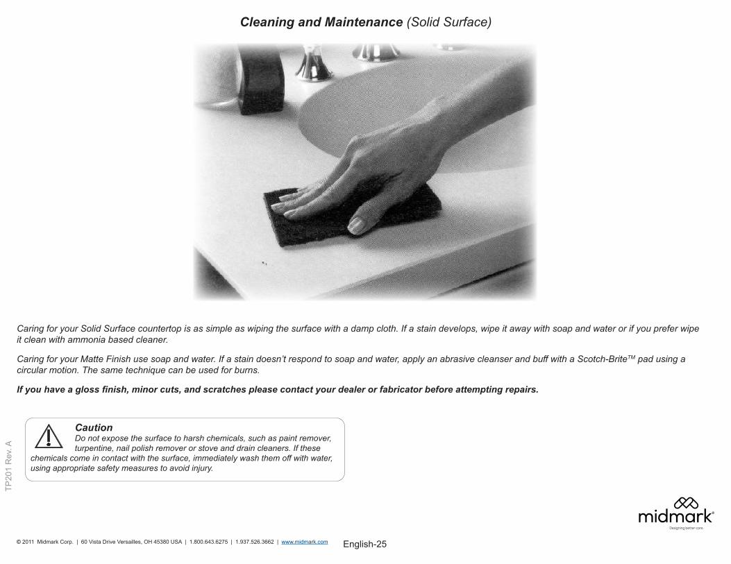
Caution Do not expose the surface to harsh chemicals, such as paint remover, turpentine, nail polish remover or stove and drain cleaners. If these chemicals come in contact with the surface, immediately wash them off with water, using appropriate safety measures to avoid injury.
Cleaning and Maintenance (Solid Surface)
Caring for your Solid Surface countertop is as simple as wiping the surface with a damp cloth. If a stain develops, wipe it away with soap and water or if you prefer wipe it clean with ammonia based cleaner.
Caring for your Matte Finish use soap and water. If a stain doesn’t respond to soap and water, apply an abrasive cleanser and buff with a Scotch-BriteTM pad using a circular motion. The same technique can be used for burns.
If you have a gloss finish, minor cuts, and scratches please contact your dealer or fabricator before attempting repairs.


![1728EX+ : Programming Guide - safe-tech · 02 ... Streamline section Streamline Streamline section Streamline section ... 1728EX+ : Programming Guide Keywords [English] Created Date:](https://img.pdfslide.net/doc/110x75/5b84d6a77f8b9aec488d14a4/1728ex-programming-guide-safe-02-streamline-section-streamline-streamline.jpg)