Embed Size (px)
Citation preview
Aruba 3000, 6000/M3 Revision C4 and Dell W-3000, W-6000M3|FIPS 140-2 Level 2 Release Supplement
Aruba 3000, 6000/M3 Revision C4 and
Dell W-3000, W-6000M3 Controllers with ArubaOS FIPS
Firmware Non-Proprietary Security Policy FIPS 140-2 Level 2 Release
Supplement
Version 2.4 December 2013
2| Aruba 3000, 6000/M3 Revision C4 and Dell W-3000, W-6000M3|FIPS 140-2 Level 2 Release Supplement
Copyright
© 2013 Aruba Networks, Inc. Aruba Networks trademarks include , Aruba Networks®, Aruba Wireless Networks®, the registered Aruba the Mobile Edge Company logo, Aruba Mobility Management System®, Mobile Edge Architecture®, People Move. Networks Must Follow®, RFProtect®, Green Island®. All rights reserved. All other trademarks are the property of their respective owners. Open Source Code
Certain Aruba products include Open Source software code developed by third parties, including software code subject to the GNU General Public License (GPL), GNU Lesser General Public License (LGPL), or other Open Source Licenses. The Open Source code used can be found at this site:
http://www.arubanetworks.com/open_source
Legal Notice
The use of Aruba Networks, Inc. switching platforms and software, by all individuals or corporations, to terminate other vendors’ VPN client devices constitutes complete acceptance of liability by that individual or corporation for this action and indemnifies, in full, Aruba Networks, Inc. from any and all legal actions that might be taken against it with respect to infringement of copyright on behalf of those vendors.
Warranty
This hardware product is protected by the standard Aruba warranty of one year parts/labor. For more information, refer to the ARUBACARE SERVICE AND SUPPORT TERMS AND CONDITIONS.
Altering this device (such as painting it) voids the warranty.
Copyright
© 2013 Aruba Networks, Inc. Aruba Networks trademarks include, Aruba Networks®, Aruba Wireless Networks®,the registered Aruba the Mobile Edge Company logo, and Aruba Mobility Management System®. Dell™, the DELL™ logo, andPowerConnect™ are trademarks of Dell Inc.
www.arubanetworks.com 1344 Crossman Avenue Sunnyvale, California 94089 Phone: 408.227.4500 Fax 408.227.4550
Aruba 3000, 6000/M3 Revision C4 and Dell W-3000, W-6000M3|FIPS 140-2 Level 2 Release Supplement |3
Preface ................................................................................................................................................................................... 6
This security policy document can be copied and distributed freely. ........................................................................... 6
Purpose of this Document ............................................................................................................................................... 6
Aruba Dell Relationship ................................................................................................................................................... 6
Related Documents ......................................................................................................................................................... 8
Additional Product Information ...................................................................................................................... 8
The Aruba 3000 and 6000/M3 Revision C4 Controllers ................................................................................................. 9
Overview ............................................................................................................................................................................ 9
Physical Description ....................................................................................................................................................... 10
Dimensions .................................................................................................................................................. 10
Cryptographic Module Boundaries .............................................................................................................. 11
Chassis ........................................................................................................................................................ 11
FIPS 140-2 Level 2 Features............................................................................................................................................ 15
Intended Level of Security ............................................................................................................................................ 15
Physical Security ............................................................................................................................................................ 16
Operational Environment .............................................................................................................................................. 16
Logical Interfaces ........................................................................................................................................................... 16
Roles and Services ........................................................................................................................................................ 17
Crypto Officer Role ...................................................................................................................................... 17
User Role ..................................................................................................................................................... 21
Authentication Mechanisms ......................................................................................................................... 22
Unauthenticated Services ............................................................................................................................ 23
Cryptographic Key Management ................................................................................................................................. 23
Implemented Algorithms .............................................................................................................................. 23
Non-FIPS Approved Algorithms .................................................................................................................. 24
Critical Security Parameters ........................................................................................................................ 24
Self-Tests ......................................................................................................................................................................... 29
Alternating Bypass State ............................................................................................................................................... 30
Mitigation of Other Attacks ............................................................................................................................................ 30
4| Aruba 3000, 6000/M3 Revision C4 and Dell W-3000, W-6000M3|FIPS 140-2 Level 2 Release Supplement
XSec ............................................................................................................................................................ 30
Wireless Intrusion Detection ........................................................................................................................ 31
Unique Station and User Classification .............................................................................................................. 31
Detecting and Disabling Rogue APs ................................................................................................................... 31
Denial of Service and Impersonation Protection ......................................................................................... 31
Man-in-the-Middle Protection ...................................................................................................................... 32
Policy Definition and Enforcement ............................................................................................................... 32
Using Wireless to Protect your Wired Network ............................................................................................ 32
Using Wireless to Protect your Existing Wireless Network .......................................................................... 32
Installing the Controller ...................................................................................................................................................... 33
Pre-Installation Checklist ............................................................................................................................................... 33
Precautions ..................................................................................................................................................................... 33
Product Examination ................................................................................................................................... 34
Package Contents ....................................................................................................................................... 34
Minimum Configuration for the Aruba 6000-400 .......................................................................................... 34
Tamper-Evident Labels ................................................................................................................................................. 35
Reading TELs .............................................................................................................................................. 35
Required TEL Locations .............................................................................................................................. 35
To Detect Opening the Chassis Cover ............................................................................................................... 36
To Detect the Removal of Any Module or Cover Plate ..................................................................................... 36
To Detect Access to Restricted Ports ................................................................................................................. 36
To Detect Access to Restricted Port ................................................................................................................... 36
To Detect Opening the Chassis Cover ............................................................................................................... 36
Applying TELs ............................................................................................................................................. 37
Ongoing Management ....................................................................................................................................................... 38
Crypto Officer Management .......................................................................................................................................... 38
User Guidance ................................................................................................................................................................ 38
Setup and Configuration ................................................................................................................................................... 39
Setting Up Your Controller ............................................................................................................................................ 39
Enabling FIPS Mode ...................................................................................................................................................... 39
Enabling FIPS with the Setup Wizard .......................................................................................................... 39
Enabling FIPS with the WebUI .................................................................................................................... 39
Disallowed FIPS Mode Configurations ....................................................................................................................... 40

Aruba 3000, 6000/M3 Revision C4 and Dell W-3000, W-6000M3|FIPS 140-2 Level 2 Release Supplement |5
6| Aruba 3000, 6000/M3 Revision C4 and Dell W-3000, W-6000M3|FIPS 140-2 Level 2 Release Supplement
Preface
This security policy document can be copied and distributed freely.
Purpose of this Document This release supplement provides information regarding the Aruba 3000,6000/M3 Revision C4 Controllers and Dell W-3000 and W-6000 M3 controllers with FIPS 140-2 Level 2 validation from Aruba Networks. The material in this supplement modifies the general Aruba hardware and firmware documentation included with this product and should be kept with your Aruba product documentation.
This supplement primarily covers the non-proprietary Cryptographic Module Security Policy for the Aruba Controller. This security policy describes how the switch meets the security requirements of FIPS 140-2 Level 2 and how to place and maintain the switch in a secure FIPS 140-2 mode. This policy was prepared as part of the FIPS 140-2 Level 2 validation of the product.
FIPS 140-2 (Federal Information Processing Standards Publication 140-2, Security Requirements for Cryptographic Modules) details the U.S. Government requirements for cryptographic modules. More information about the FIPS 140-2 standard and validation program is available on the National Institute of Standards and Technology (NIST) Web-site at:
http://csrc.nist.gov/groups/STM/cmvp/index.html
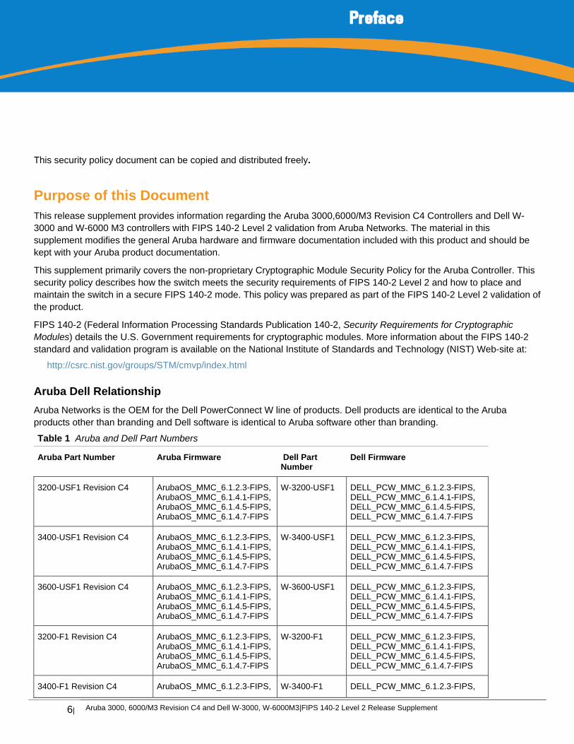
Aruba Dell Relationship
Aruba Networks is the OEM for the Dell PowerConnect W line of products. Dell products are identical to the Aruba products other than branding and Dell software is identical to Aruba software other than branding.
Table 1 Aruba and Dell Part Numbers
Aruba Part Number Aruba Firmware Dell Part Number
Dell Firmware
3200-USF1 Revision C4 ArubaOS_MMC_6.1.2.3-FIPS, ArubaOS_MMC_6.1.4.1-FIPS, ArubaOS_MMC_6.1.4.5-FIPS, ArubaOS_MMC_6.1.4.7-FIPS
W-3200-USF1 DELL_PCW_MMC_6.1.2.3-FIPS, DELL_PCW_MMC_6.1.4.1-FIPS, DELL_PCW_MMC_6.1.4.5-FIPS, DELL_PCW_MMC_6.1.4.7-FIPS
3400-USF1 Revision C4 ArubaOS_MMC_6.1.2.3-FIPS, ArubaOS_MMC_6.1.4.1-FIPS, ArubaOS_MMC_6.1.4.5-FIPS, ArubaOS_MMC_6.1.4.7-FIPS
W-3400-USF1 DELL_PCW_MMC_6.1.2.3-FIPS, DELL_PCW_MMC_6.1.4.1-FIPS, DELL_PCW_MMC_6.1.4.5-FIPS, DELL_PCW_MMC_6.1.4.7-FIPS
3600-USF1 Revision C4 ArubaOS_MMC_6.1.2.3-FIPS, ArubaOS_MMC_6.1.4.1-FIPS, ArubaOS_MMC_6.1.4.5-FIPS, ArubaOS_MMC_6.1.4.7-FIPS
W-3600-USF1 DELL_PCW_MMC_6.1.2.3-FIPS, DELL_PCW_MMC_6.1.4.1-FIPS, DELL_PCW_MMC_6.1.4.5-FIPS, DELL_PCW_MMC_6.1.4.7-FIPS
3200-F1 Revision C4 ArubaOS_MMC_6.1.2.3-FIPS, ArubaOS_MMC_6.1.4.1-FIPS, ArubaOS_MMC_6.1.4.5-FIPS, ArubaOS_MMC_6.1.4.7-FIPS
W-3200-F1 DELL_PCW_MMC_6.1.2.3-FIPS, DELL_PCW_MMC_6.1.4.1-FIPS, DELL_PCW_MMC_6.1.4.5-FIPS, DELL_PCW_MMC_6.1.4.7-FIPS
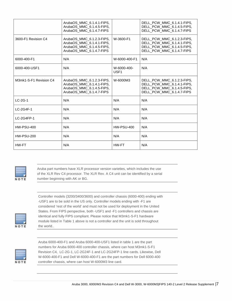
3400-F1 Revision C4 ArubaOS_MMC_6.1.2.3-FIPS, W-3400-F1 DELL_PCW_MMC_6.1.2.3-FIPS,
Aruba 3000, 6000/M3 Revision C4 and Dell W-3000, W-6000M3|FIPS 140-2 Level 2 Release Supplement |7
ArubaOS_MMC_6.1.4.1-FIPS, ArubaOS_MMC_6.1.4.5-FIPS, ArubaOS_MMC_6.1.4.7-FIPS
DELL_PCW_MMC_6.1.4.1-FIPS, DELL_PCW_MMC_6.1.4.5-FIPS, DELL_PCW_MMC_6.1.4.7-FIPS
3600-F1 Revision C4 ArubaOS_MMC_6.1.2.3-FIPS, ArubaOS_MMC_6.1.4.1-FIPS, ArubaOS_MMC_6.1.4.5-FIPS, ArubaOS_MMC_6.1.4.7-FIPS
W-3600-F1 DELL_PCW_MMC_6.1.2.3-FIPS, DELL_PCW_MMC_6.1.4.1-FIPS, DELL_PCW_MMC_6.1.4.5-FIPS, DELL_PCW_MMC_6.1.4.7-FIPS
6000-400-F1 N/A W-6000-400-F1 N/A
6000-400-USF1 N/A W-6000-400-USF1
N/A
M3mk1-S-F1 Revision C4 ArubaOS_MMC_6.1.2.3-FIPS, ArubaOS_MMC_6.1.4.1-FIPS, ArubaOS_MMC_6.1.4.5-FIPS, ArubaOS_MMC_6.1.4.7-FIPS
W-6000M3 DELL_PCW_MMC_6.1.2.3-FIPS, DELL_PCW_MMC_6.1.4.1-FIPS, DELL_PCW_MMC_6.1.4.5-FIPS, DELL_PCW_MMC_6.1.4.7-FIPS
LC-2G-1 N/A N/A N/A
LC-2G4F-1 N/A N/A N/A
LC-2G4FP-1 N/A N/A N/A
HW-PSU-400 N/A HW-PSU-400 N/A
HW-PSU-200 N/A N/A N/A
HW-FT N/A HW-FT N/A
Aruba part numbers have XLR processor version varieties, which includes the use
of the XLR Rev C4 processor. The XLR Rev. A C4 unit can be identified by a serial
number beginning with AK or BG.
Controller models (3200/3400/3600) and controller chassis (6000-400) ending with
-USF1 are to be sold in the US only. Controller models ending with -F1 are
considered ‘rest of the world’ and must not be used for deployment in the United
States. From FIPS perspective, both -USF1 and -F1 controllers and chassis are
identical and fully FIPS compliant. Please notice that M3mk1-S-F1 hardware
module listed in Table 1 above is not a controller and the unit is sold throughout
the world..
Aruba 6000-400-F1 and Aruba 6000-400-USF1 listed in table 1 are the part
numbers for Aruba 6000-400 controller chassis, where can host M3mk1-S-F1
Revision C4, LC-2G-1, LC-2G24F-1 and LC-2G24FP-1 line cards. Likewise, Dell
W-6000-400-F1 and Dell W-6000-400-F1 are the part numbers for Dell 6000-400
controller chassis, where can host W-6000M3 line card.
8| Aruba 3000, 6000/M3 Revision C4 and Dell W-3000, W-6000M3|FIPS 140-2 Level 2 Release Supplement
There is no Dell equivalent for the LC-2G-1, LC- 2G24F-1, or LC-2G24FP-1. Aruba
Line Cards LC-2G-1, LC-2G24F-1 and LC2G24FP-1 are no longer sold by Aruba,
but are supported by the Aruba 6000-400 chassis until November 1, 2015. These
optional line cards can be replaced by the hardware M3mk1-S-F1 Revision C4
accordingly. Please notice that none of the Aruba Line cards (LC-2G-1, LC-2G24F-
1 and LC2G24FP-1) performs cryptographic operations.
As both Aruba and Dell products are identical, throughout this document, the
descriptions to each Aruba product will be applied to its respective Dell product
accordingly.
Related Documents The following items are part of the complete installation and operations documentation included with this product:
Aruba 6000 Mobility Controller Installation Guide
Aruba 3000-series Mobility Controller Installation Guide
ArubaOS 6.1 User Guide
ArubaOS 6.1 CLI Reference Guide
ArubaOS 6.1 Quick Start Guide
ArubaOS 6.1 Upgrade Guide
Aruba AP Installation Guides
Additional Product Information
More information is available from the following sources:
The Aruba Networks Web-site contains information on the full line of products from Aruba Networks:
http://www.arubanetworks.com
The Dell Web site contains information on the full line of products from Dell.
http://www.dell.com/
The NIST Validated Modules Web-site contains contact information for answers to technical or sales-related questions for the product:
http://csrc.nist.gov/groups/STM/cmvp/index.html
Aruba 3000, 6000/M3 Revision C4 and Dell W-3000, W-6000M3|FIPS 140-2 Level 2 Release Supplement |9
The Aruba 3000 and 6000/M3 Revision C4 Controllers This chapter introduces the Aruba 3000 and 6000/M3 Revision C4 Controllers with FIPS 140-2 Level 2 validation. It describes the purpose of the controller, its physical attributes, and its interfaces.
Overview Aruba Networks has developed a purpose-built Wireless LAN voice and data switching solution designed to specifically address the needs of large-scale WiFi network deployments for Government agencies and global enterprises. The Aruba Controller solution provides advanced security and management of the corporate RF environment and enforces User security and service policies to both wired and wireless users.
The Aruba Wireless FIPS 140-2 Level 2 validated Controlling platform serves value-add high speed data and QoS assured voice services to thousands of mobile wireless users simultaneously from a single, cost effective, redundant and scalable solution that performs centralized functionality for:
Uncompromised User security, authentication and encryption
Stateful LAN-speed firewalling
VPN termination
Wireless intrusion detection, prevention and rogue containment
RF Air monitoring
Powerful packet processing switching
Mobility management
Advanced RF management
Advanced User and network service / element management
The Aruba FIPS 140-2 Level 2 validated Controller solution is a highly available, modular and upgradeable switching
platform which connects, con-trols, secures, and intelligently integrates wireless Access Points and Air Monitors into the
wired LAN, serving as a gateway between a wireless network and the wired network. The wireless network traffic from the
APs is securely tunneled over a L2/L3 network and is terminated centrally on the switch via 10/100/1000 Ethernet physical
interfaces where it is authenticated, assigned the appropriate security policies and VLAN assignments and up-linked onto
the wired network.
The Aruba Controller solution consists of the three major components:
Aruba Controller. This is an enterprise-class switch into which multiple Access Points (APs) and Air Monitors (AMs)
may be directly or in-directly (tunneled over a L2/L3 network) connected and controlled.
Aruba Wireless Access Point. This is a next-generation wireless transceiver which func-tions as an AP or AM.
Although third-party APs can be used with the Aruba WLAN sys-tem, the Aruba AP provides the most comprehensive
features and simpler integration.
Aruba ArubaOS Switch firmware. This firmware intelligently integrates the Controller and APs to provide load
balancing, rate limiting, self-healing, authentication, mobility, security, firewalls, encryption, and centralization for
monitoring and upgrades.
The Aruba switch configurations validated during the cryptographic module testing included:
10| Aruba 3000, 6000/M3 Revision C4 and Dell W-3000, W-6000M3|FIPS 140-2 Level 2 Release Supplement
Aruba 3200 Revision C4
Aruba 3400 Revision C4
Aruba 3600 Revision C4
There are two versions of the M3mk1-S-F1, Revision C4. Revision C4 supports AES-GCM (see “Cryptographic Key
Management” on page 21 for more information).
Aruba 6000-400 chassis (no more than four Aruba line cards, including the combinations among M3mk1-S-F1
[Revision C4], LC-2G-1, LC-2G24F-1, or LC-2G24FP-1, in a single hardware configuration). Please notice that the
use of LC-2G-1, LC-2G24F-1 and LC-2G24FP-1 is optional, but at least one M3mk1-S-F1 is required in a single
hardware configuration).
The exact firmware versions validated were ArubaOS_MMC_6.1.2.3-FIPS, ArubaOS_MMC_6.1.4.1-FIPS,
ArubaOS_MMC_6.1.4.5-FIPS, ArubaOS_MMC_6.1.4.7-FIPS and Dell_PCW_MMC_6.1.2.3-FIPS,
DELL_PCW_MMC_6.1.4.1-FIPS, DELL_PCW_MMC_6.1.4.5-FIPS, DELL_PCW_MMC_6.1.4.7-FIPS
Physical Description
Dimensions
The Aruba 6000-400 controller chassis has the following physical dimensions:
3 RU chassis is designed to fit in a standard 19" rack. A separate mounting kit is needed for a 23" rack.
Size:
Width 17.4" (19" rack width)
Height 5.25" (3 RU)—3.5" for the card slots plus 1 RU for the power supply slots
Depth 14"
Maximum weight: Up to 58 lbs (26.5 kg)
The Aruba 3200 Controller has the following physical dimensions:
1 RU chassis is designed to fit in a standard 19" rack with the included mounting kit. A separate mounting kit is needed
for a 23" rack.
Size:
Width 13.8"
Height 1.75" (1 RU)
Depth 11.7"
Maximum weight: Up to 7.1 lbs (3.2 kg)
The Aruba 3400 and 3600 Controllers have the following physical dimensions:
1 RU chassis is designed to fit in a standard 19" rack with the included mounting kit. A separate mounting kit is needed
for a 23" rack.
Size:
Width 13.8"
Height 1.75" (1 RU)
Depth 11.7"
Maximum weight: Up to 7.4 lbs (3.4 kg)
Aruba 3000, 6000/M3 Revision C4 and Dell W-3000, W-6000M3|FIPS 140-2 Level 2 Release Supplement |11
Cryptographic Module Boundaries
For FIPS 140-2 Level 2 validation, the Controller has been validated as a multi-chip standalone cryptographic module. The steel chassis physically encloses the complete set of hardware (including supervisor cards, line cards, the fan tray, the power supplies utilized within the Aruba 6000-400 controller) and firmware components and represents the cryptographic boundary of the switch. The cryptographic boundary is defined as encompassing the top, front, left, right, rear, and bottom surfaces of the chassis.
Chassis
The Aruba 6000-400 controller chassis is designed to be modular. All of the modular components, consisting of the switching supervisor and network line cards, the fan tray, and the power supplies, are accessible from the front of the chassis.
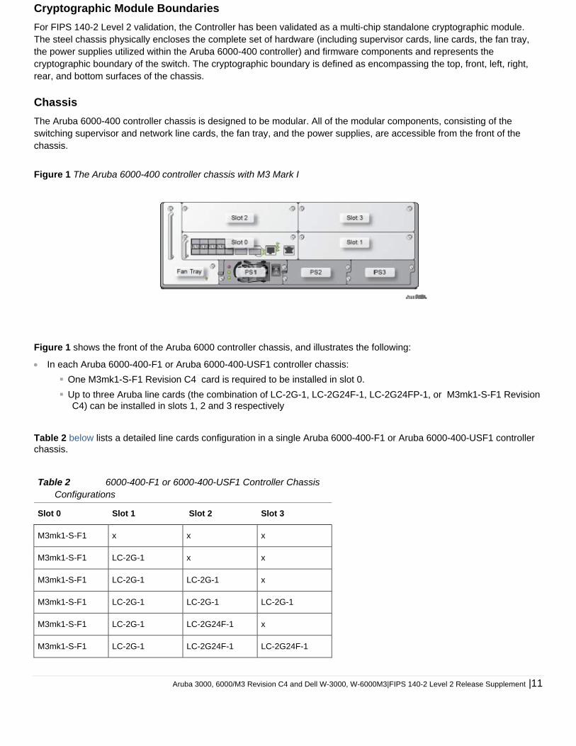
Figure 1 The Aruba 6000-400 controller chassis with M3 Mark I
Figure 1 shows the front of the Aruba 6000 controller chassis, and illustrates the following:
In each Aruba 6000-400-F1 or Aruba 6000-400-USF1 controller chassis:
One M3mk1-S-F1 Revision C4 card is required to be installed in slot 0.
Up to three Aruba line cards (the combination of LC-2G-1, LC-2G24F-1, LC-2G24FP-1, or M3mk1-S-F1 Revision C4) can be installed in slots 1, 2 and 3 respectively
Table 2 below lists a detailed line cards configuration in a single Aruba 6000-400-F1 or Aruba 6000-400-USF1 controller chassis.
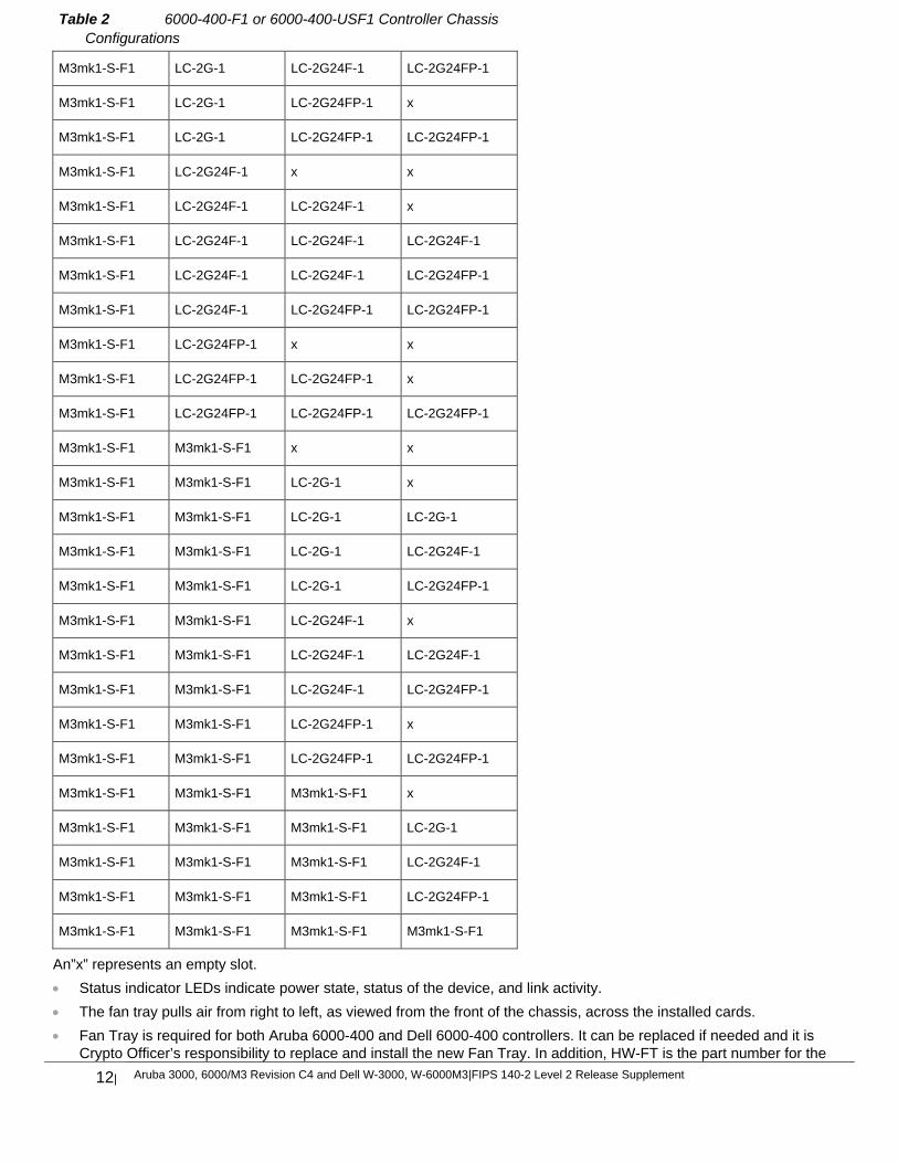
Table 2 6000-400-F1 or 6000-400-USF1 Controller Chassis Configurations
Slot 0 Slot 1 Slot 2 Slot 3
M3mk1-S-F1 x x x
M3mk1-S-F1 LC-2G-1 x x
M3mk1-S-F1 LC-2G-1 LC-2G-1 x
M3mk1-S-F1 LC-2G-1 LC-2G-1 LC-2G-1
M3mk1-S-F1 LC-2G-1 LC-2G24F-1 x
M3mk1-S-F1 LC-2G-1 LC-2G24F-1 LC-2G24F-1
12| Aruba 3000, 6000/M3 Revision C4 and Dell W-3000, W-6000M3|FIPS 140-2 Level 2 Release Supplement
Table 2 6000-400-F1 or 6000-400-USF1 Controller Chassis Configurations
M3mk1-S-F1 LC-2G-1 LC-2G24F-1 LC-2G24FP-1
M3mk1-S-F1 LC-2G-1 LC-2G24FP-1 x
M3mk1-S-F1 LC-2G-1 LC-2G24FP-1 LC-2G24FP-1
M3mk1-S-F1 LC-2G24F-1 x x
M3mk1-S-F1 LC-2G24F-1 LC-2G24F-1 x
M3mk1-S-F1 LC-2G24F-1 LC-2G24F-1 LC-2G24F-1
M3mk1-S-F1 LC-2G24F-1 LC-2G24F-1 LC-2G24FP-1
M3mk1-S-F1 LC-2G24F-1 LC-2G24FP-1 LC-2G24FP-1
M3mk1-S-F1 LC-2G24FP-1 x x
M3mk1-S-F1 LC-2G24FP-1 LC-2G24FP-1 x
M3mk1-S-F1 LC-2G24FP-1 LC-2G24FP-1 LC-2G24FP-1
M3mk1-S-F1 M3mk1-S-F1 x x
M3mk1-S-F1 M3mk1-S-F1 LC-2G-1 x
M3mk1-S-F1 M3mk1-S-F1 LC-2G-1 LC-2G-1
M3mk1-S-F1 M3mk1-S-F1 LC-2G-1 LC-2G24F-1
M3mk1-S-F1 M3mk1-S-F1 LC-2G-1 LC-2G24FP-1
M3mk1-S-F1 M3mk1-S-F1 LC-2G24F-1 x
M3mk1-S-F1 M3mk1-S-F1 LC-2G24F-1 LC-2G24F-1
M3mk1-S-F1 M3mk1-S-F1 LC-2G24F-1 LC-2G24FP-1
M3mk1-S-F1 M3mk1-S-F1 LC-2G24FP-1 x
M3mk1-S-F1 M3mk1-S-F1 LC-2G24FP-1 LC-2G24FP-1
M3mk1-S-F1 M3mk1-S-F1 M3mk1-S-F1 x
M3mk1-S-F1 M3mk1-S-F1 M3mk1-S-F1 LC-2G-1
M3mk1-S-F1 M3mk1-S-F1 M3mk1-S-F1 LC-2G24F-1
M3mk1-S-F1 M3mk1-S-F1 M3mk1-S-F1 LC-2G24FP-1
M3mk1-S-F1 M3mk1-S-F1 M3mk1-S-F1 M3mk1-S-F1
An”x” represents an empty slot.
Status indicator LEDs indicate power state, status of the device, and link activity.
The fan tray pulls air from right to left, as viewed from the front of the chassis, across the installed cards.
Fan Tray is required for both Aruba 6000-400 and Dell 6000-400 controllers. It can be replaced if needed and it is Crypto Officer’s responsibility to replace and install the new Fan Tray. In addition, HW-FT is the part number for the
Aruba 3000, 6000/M3 Revision C4 and Dell W-3000, W-6000M3|FIPS 140-2 Level 2 Release Supplement |13
fan tray used in both Aruba 6000-400-F1, Aruba 6000-400-USF1, Dell W-6000-400-F1 and Dell W-6000-400-USF1 chassis.
PS1, PS2, and PS3 are for Power Supply modules. The number of power supplies required for the system depends on the number of Line Cards installed, and whether to include redundancy for fault tolerance (please refer to the Aruba 6000 Mobility Controller Installation Guide). It is Crypto Officer’s responsibility to install the power supplies. The two available power supplies are:
200 W Power Supply (HW-PSU-200) can be used in Aruba 6000-400 controller
400 W Power Supply (HW-PSU-400) can be used in Aruba 6000-400 or Dell 6000-400 controllers
When using more than one power supply, verify that they are all of the same type. Do not mix 200 W and 400 W
power supplies in the same chassis.
HW-PSU-400 and HW-PSU-200 are the part numbers for the power supply used in
Aruba 6000-400-F1 or Aruba 6000-400-USF1 chassis; HW-PSU-400 is the only type of
power supply used in Dell W-6000-400-F1 or W-6000-400-USF1 chassis.
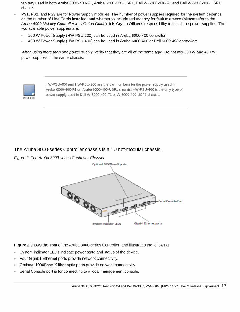
The Aruba 3000-series Controller chassis is a 1U not-modular chassis.
Figure 2 The Aruba 3000-series Controller Chassis
Figure 2 shows the front of the Aruba 3000-series Controller, and illustrates the following:
System indicator LEDs indicate power state and status of the device.
Four Gigabit Ethernet ports provide network connectivity.
Optional 1000Base-X fiber optic ports provide network connectivity.
Serial Console port is for connecting to a local management console.

14| Aruba 3000, 6000/M3 Revision C4 and Dell W-3000, W-6000M3|FIPS 140-2 Level 2 Release Supplement
Aruba 3000, 6000/M3 Revision C4 and Dell W-3000, W-6000M3|FIPS 140-2 Level 2 Release Supplement |15
FIPS 140-2 Level 2 Features
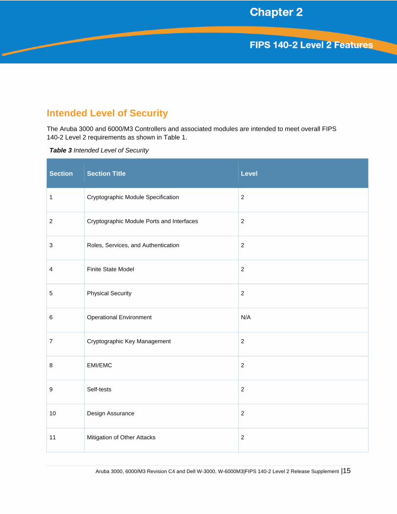
Intended Level of Security
The Aruba 3000 and 6000/M3 Controllers and associated modules are intended to meet overall FIPS 140-2 Level 2 requirements as shown in Table 1.
Table 3 Intended Level of Security
Section Section Title Level
1 Cryptographic Module Specification 2
2 Cryptographic Module Ports and Interfaces 2
3 Roles, Services, and Authentication 2
4 Finite State Model 2
5 Physical Security 2
6 Operational Environment N/A
7 Cryptographic Key Management 2
8 EMI/EMC 2
9 Self-tests 2
10 Design Assurance 2
11 Mitigation of Other Attacks 2
16| Aruba 3000, 6000/M3 Revision C4 and Dell W-3000, W-6000M3|FIPS 140-2 Level 2 Release Supplement
Physical Security
The Aruba Controller is a scalable, multi-processor standalone network device and is enclosed in a robust steel housing. The switch enclosure is resistant to probing and is opaque within the visible spectrum. The enclosure of the switch has been designed to satisfy FIPS 140-2 Level 2 physical security requirements.
For the Aruba 6000-400 the left, top, right, and bottom surfaces are irremovable. The rear panel can be removed by unscrewing fifteen screws. The switch has a number of components at front side, including four slots for supervisor and line cards, one fan tray, and three power supplies. Each of the components is attached with two screws.
For the Aruba 3000-series the left, right, front, rear, and bottom surfaces are irremovable. The top panel can be removed by unscrewing two screws. A metallic opaque shield is installed at the factory during manufacturing and can not be removed by the User.
For physical security, the Aruba 6000-400 chassis requires Tamper-Evident Labels (TELs) to allow the detection of the opening of the chassis covers; the removal or replacement of any module or cover plate, and to block the Serial console port.
The Aruba 3000-series Controllers require Tamper-Evident Labels (TELs) to allow the detection of the opening of the chassis cover and to block the Serial console port.
To protect the Aruba 3000 and 6000/M3 Controllers from any tampering with the product, TELs should be applied by the Crypto Officer as covered under “Tamper-Evident Labels” on page 33.
Operational Environment
The operational environment is non-modifiable. The control plane Operating System (OS) is Linux, a real-time, multi-threaded operating system that supports memory protection between processes. Access to the underlying Linux implementation is not provided directly. Only Aruba Networks provided interfaces are used, and the CLI is a restricted command set.
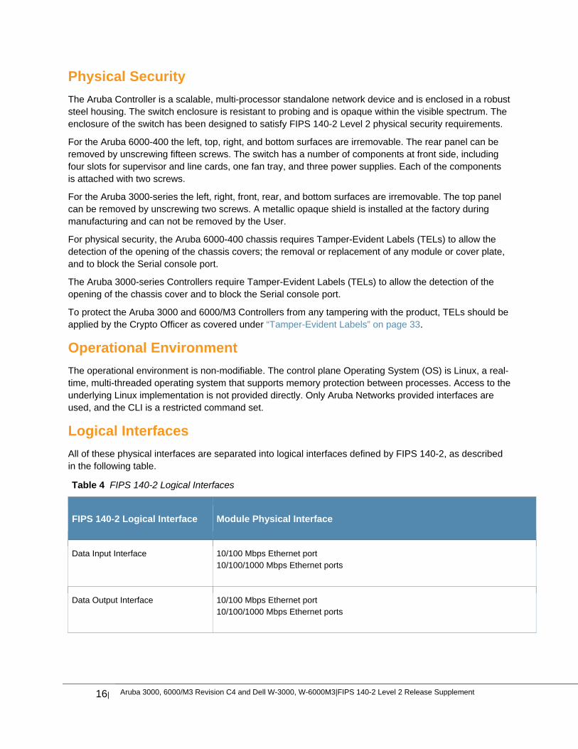
Logical Interfaces
All of these physical interfaces are separated into logical interfaces defined by FIPS 140-2, as described in the following table.
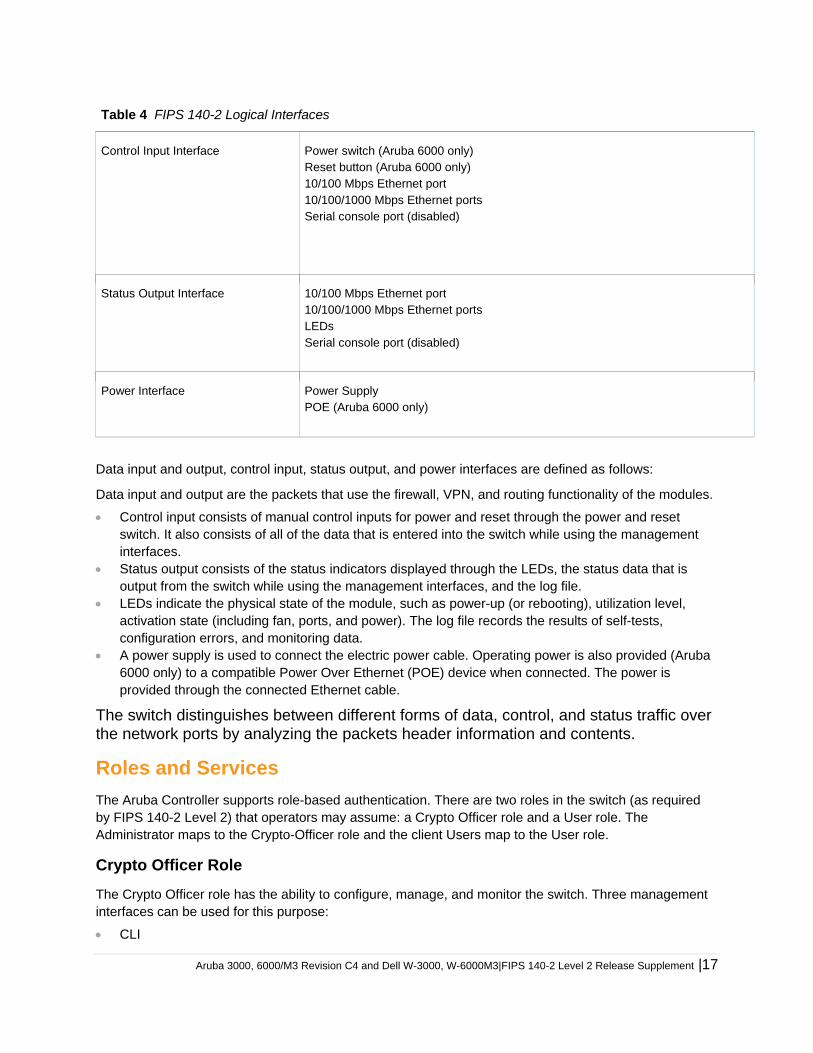
Table 4 FIPS 140-2 Logical Interfaces
FIPS 140-2 Logical Interface Module Physical Interface
Data Input Interface 10/100 Mbps Ethernet port 10/100/1000 Mbps Ethernet ports
Data Output Interface 10/100 Mbps Ethernet port 10/100/1000 Mbps Ethernet ports
Aruba 3000, 6000/M3 Revision C4 and Dell W-3000, W-6000M3|FIPS 140-2 Level 2 Release Supplement |17
Table 4 FIPS 140-2 Logical Interfaces
Control Input Interface Power switch (Aruba 6000 only) Reset button (Aruba 6000 only) 10/100 Mbps Ethernet port 10/100/1000 Mbps Ethernet ports Serial console port (disabled)
Status Output Interface 10/100 Mbps Ethernet port 10/100/1000 Mbps Ethernet ports LEDs Serial console port (disabled)
Power Interface Power Supply POE (Aruba 6000 only)
Data input and output, control input, status output, and power interfaces are defined as follows:
Data input and output are the packets that use the firewall, VPN, and routing functionality of the modules.
Control input consists of manual control inputs for power and reset through the power and reset switch. It also consists of all of the data that is entered into the switch while using the management interfaces.
Status output consists of the status indicators displayed through the LEDs, the status data that is output from the switch while using the management interfaces, and the log file.
LEDs indicate the physical state of the module, such as power-up (or rebooting), utilization level, activation state (including fan, ports, and power). The log file records the results of self-tests, configuration errors, and monitoring data.
A power supply is used to connect the electric power cable. Operating power is also provided (Aruba 6000 only) to a compatible Power Over Ethernet (POE) device when connected. The power is provided through the connected Ethernet cable.
The switch distinguishes between different forms of data, control, and status traffic over the network ports by analyzing the packets header information and contents.
Roles and Services
The Aruba Controller supports role-based authentication. There are two roles in the switch (as required by FIPS 140-2 Level 2) that operators may assume: a Crypto Officer role and a User role. The Administrator maps to the Crypto-Officer role and the client Users map to the User role.
Crypto Officer Role
The Crypto Officer role has the ability to configure, manage, and monitor the switch. Three management interfaces can be used for this purpose:
CLI
18| Aruba 3000, 6000/M3 Revision C4 and Dell W-3000, W-6000M3|FIPS 140-2 Level 2 Release Supplement
The Crypto Officer can use the CLI to perform non-security-sensitive and security-sensitive monitoring and configuration. The CLI can be accessed remotely by using the SSHv2 secured management session over the Ethernet ports or locally over the serial port. In FIPS mode, the serial port is disabled.
Web Interface
The Crypto Officer can use the Web Interface as an alternative to the CLI. The Web Interface provides a highly intuitive, graphical interface for a comprehensive set of switch management tools. The Web Interface can be accessed from a TLS-enabled Web browser using HTTPS (HTTP with Secure Socket Layer) on logical port 4343.
Bootrom Monitor Mode
In Bootrom monitor mode, the Crypto Officer can reboot, update the Bootrom, issue file system-related commands, modify network parameters, and issue various show commands. The Crypto Officer can only enter this mode by pressing any key during the first four seconds of initialization. Bootrom Monitor Mode is disabled in FIPS mode.
The Crypto Officer can also use SNMPv1/2c/3 to remotely perform non-security-sensitive monitoring and
use get and getnext commands. See the table below for descriptions of the services available to the
Crypto Officer role.
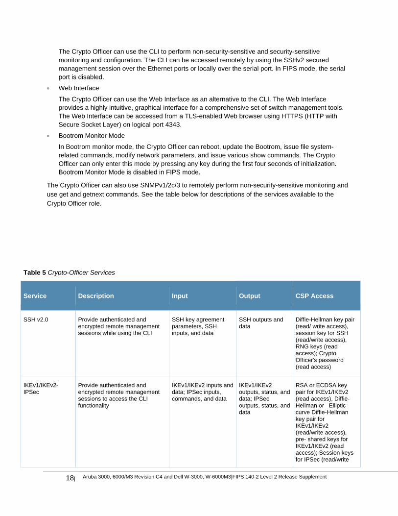
Table 5 Crypto-Officer Services
Service Description Input Output CSP Access
SSH v2.0 Provide authenticated and encrypted remote management sessions while using the CLI
SSH key agreement parameters, SSH inputs, and data
SSH outputs and data
Diffie-Hellman key pair (read/ write access), session key for SSH (read/write access), RNG keys (read access); Crypto Officer's password (read access)
IKEv1/IKEv2-IPSec
Provide authenticated and encrypted remote management sessions to access the CLI functionality
IKEv1/IKEv2 inputs and data; IPSec inputs, commands, and data
IKEv1/IKEv2 outputs, status, and data; IPSec outputs, status, and data
RSA or ECDSA key pair for IKEv1/IKEv2 (read access), Diffie-Hellman or Elliptic curve Diffie-Hellman key pair for IKEv1/IKEv2 (read/write access), pre- shared keys for IKEv1/IKEv2 (read access); Session keys for IPSec (read/write
Aruba 3000, 6000/M3 Revision C4 and Dell W-3000, W-6000M3|FIPS 140-2 Level 2 Release Supplement |19
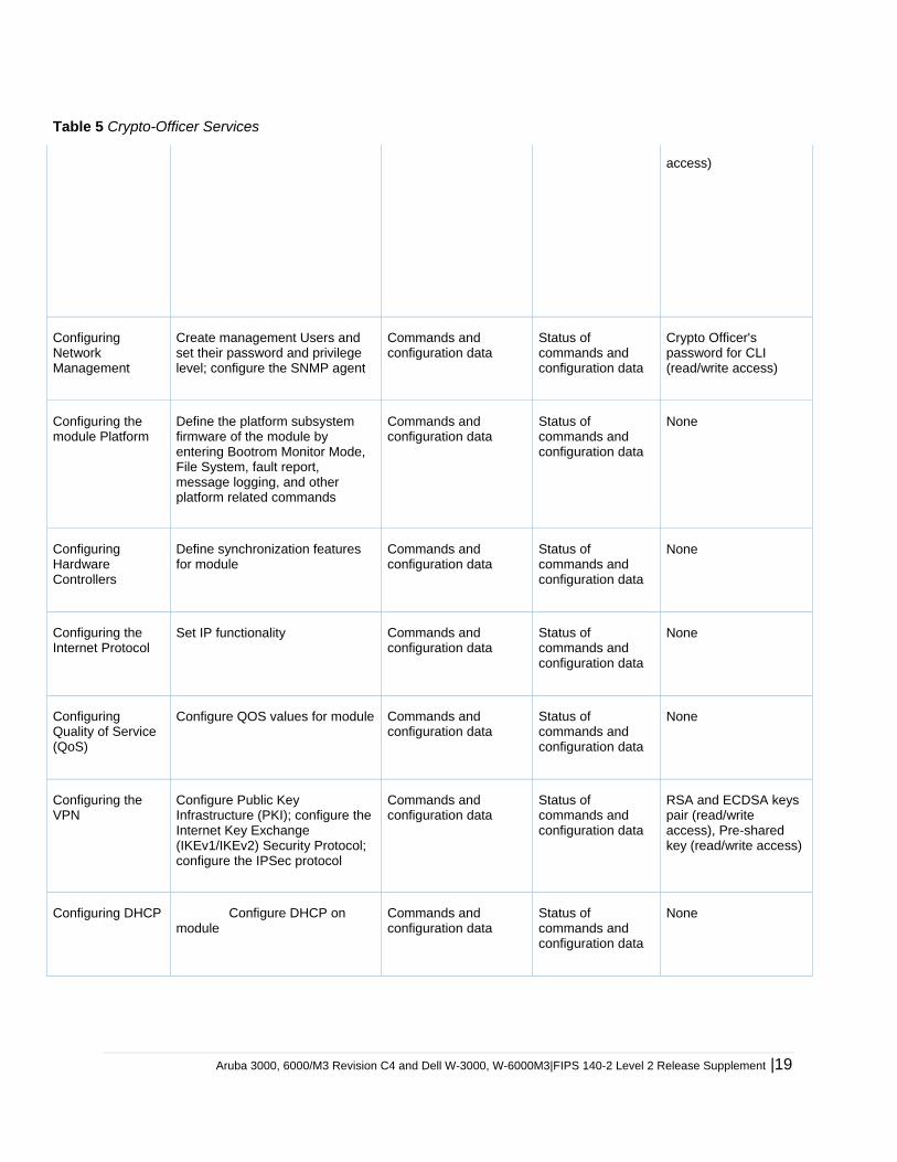
Table 5 Crypto-Officer Services
access)
Configuring Network Management
Create management Users and set their password and privilege level; configure the SNMP agent
Commands and configuration data
Status of commands and configuration data
Crypto Officer's password for CLI (read/write access)
Configuring the module Platform
Define the platform subsystem firmware of the module by entering Bootrom Monitor Mode, File System, fault report, message logging, and other platform related commands
Commands and configuration data
Status of commands and configuration data
None
Configuring Hardware Controllers
Define synchronization features for module
Commands and configuration data
Status of commands and configuration data
None
Configuring the Internet Protocol
Set IP functionality Commands and configuration data
Status of commands and configuration data
None
Configuring Quality of Service (QoS)
Configure QOS values for module Commands and configuration data
Status of commands and configuration data
None
Configuring the VPN
Configure Public Key Infrastructure (PKI); configure the Internet Key Exchange (IKEv1/IKEv2) Security Protocol; configure the IPSec protocol
Commands and configuration data
Status of commands and configuration data
RSA and ECDSA keys pair (read/write access), Pre-shared key (read/write access)
Configuring DHCP Configure DHCP on module
Commands and configuration data
Status of commands and configuration data
None
20| Aruba 3000, 6000/M3 Revision C4 and Dell W-3000, W-6000M3|FIPS 140-2 Level 2 Release Supplement
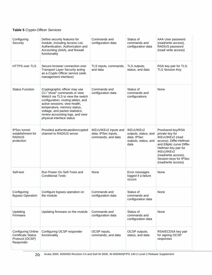
Table 5 Crypto-Officer Services
Configuring Security
Define security features for module, including Access List, Authentication, Authorization and Accounting (AAA), and firewall functionality
Commands and configuration data
Status of commands and configuration data
AAA User password (read/write access), RADIUS password (read/ write access)
HTTPS over TLS Secure browser connection over Transport Layer Security acting as a Crypto Officer service (web management interface)
TLS inputs, commands, and data
TLS outputs, status, and data
RSA key pair for TLS; TLS Session Key
Status Function Cryptographic officer may use CLI "show" commands or view WebUI via TLS to view the switch configuration, routing tables, and active sessions; view health, temperature, memory status, voltage, and packet statistics; review accounting logs, and view physical interface status
Commands and configuration data
Status of commands and configurations
None
IPSec tunnel establishment for RADIUS protection
Provided authenticated/encrypted channel to RADIUS server
IKEv1/IKEv2 inputs and data; IPSec inputs, commands, and data
IKEv1/IKEv2 outputs, status, and data; IPSec outputs, status, and data
Preshared key/RSA private key for IKEv1/IKEv2 (read access), Diffie-Hellman and Elliptic curve Diffie-Hellman key pair for IKEv1/IKEv2 (read/write access), Session keys for IPSec (read/write access)
Self-test Run Power On Self-Tests and Conditional Tests
None Error messages logged if a failure occurs
None
Configuring Bypass Operation
Configure bypass operation on the module
Commands and configuration data
Status of commands and configuration data
None
Updating Firmware
Updating firmware on the module Commands and configuration data
Status of commands and configuration data
None
Configuring Online Certificate Status Protocol (OCSP) Responder
Configuring OCSP responder functionality
OCSP inputs, commands, and data
OCSP outputs, status, and data
RSA/ECDSA key pair for signing OCSP responses
Aruba 3000, 6000/M3 Revision C4 and Dell W-3000, W-6000M3|FIPS 140-2 Level 2 Release Supplement |21
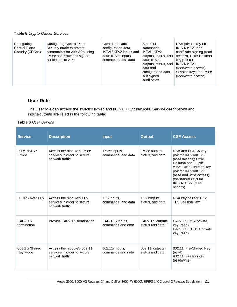
Table 5 Crypto-Officer Services
Configuring Control Plane Security (CPSec)
Configuring Control Plane Security mode to protect communication with APs using IPSec and issue self signed certificates to APs
Commands and configuration data, IKEv1/IKEv2 inputs and data; IPSec inputs, commands, and data
Status of commands, IKEv1/IKEv2 outputs, status, and data; IPSec outputs, status, and data and configuration data, self signed certificates
RSA private key for IKEv1/IKEv2 and certificate signing (read access), Diffie-Hellman key pair for IKEv1/IKEv2 (read/write access), Session keys for IPSec (read/write access)
User Role
The User role can access the switch’s IPSec and IKEv1/IKEv2 services. Service descriptions and inputs/outputs are listed in the following table:
Table 6 User Service
Service Description Input Output CSP Access
IKEv1/IKEv2-IPSec
Access the module's IPSec services in order to secure network traffic
IPSec inputs, commands, and data
IPSec outputs, status, and data
RSA and ECDSA key pair for IKEv1/IKEv2 (read access); Diffie-Hellman and Elliptic curve Diffie-Hellman key pair for IKEv1/IKEv2 (read and write access); pre-shared keys for IKEv1/IKEv2 (read access)
HTTPS over TLS Access the module’s TLS services in order to secure network traffic
TLS inputs, commands, and data
TLS outputs, status, and data
RSA key pair for TLS; TLS Session Key
EAP-TLS termination
Provide EAP-TLS termination EAP-TLS inputs, commands and data
EAP-TLS outputs, status and data
EAP-TLS RSA private key (read) EAP-TLS ECDSA private key (read)
802.11i Shared Key Mode
Access the module’s 802.11i services in order to secure network traffic
802.11i inputs, commands and data
802.11i outputs, status and data
802.11i Pre-Shared Key (read) 802.11i Session key (read/write)
22| Aruba 3000, 6000/M3 Revision C4 and Dell W-3000, W-6000M3|FIPS 140-2 Level 2 Release Supplement
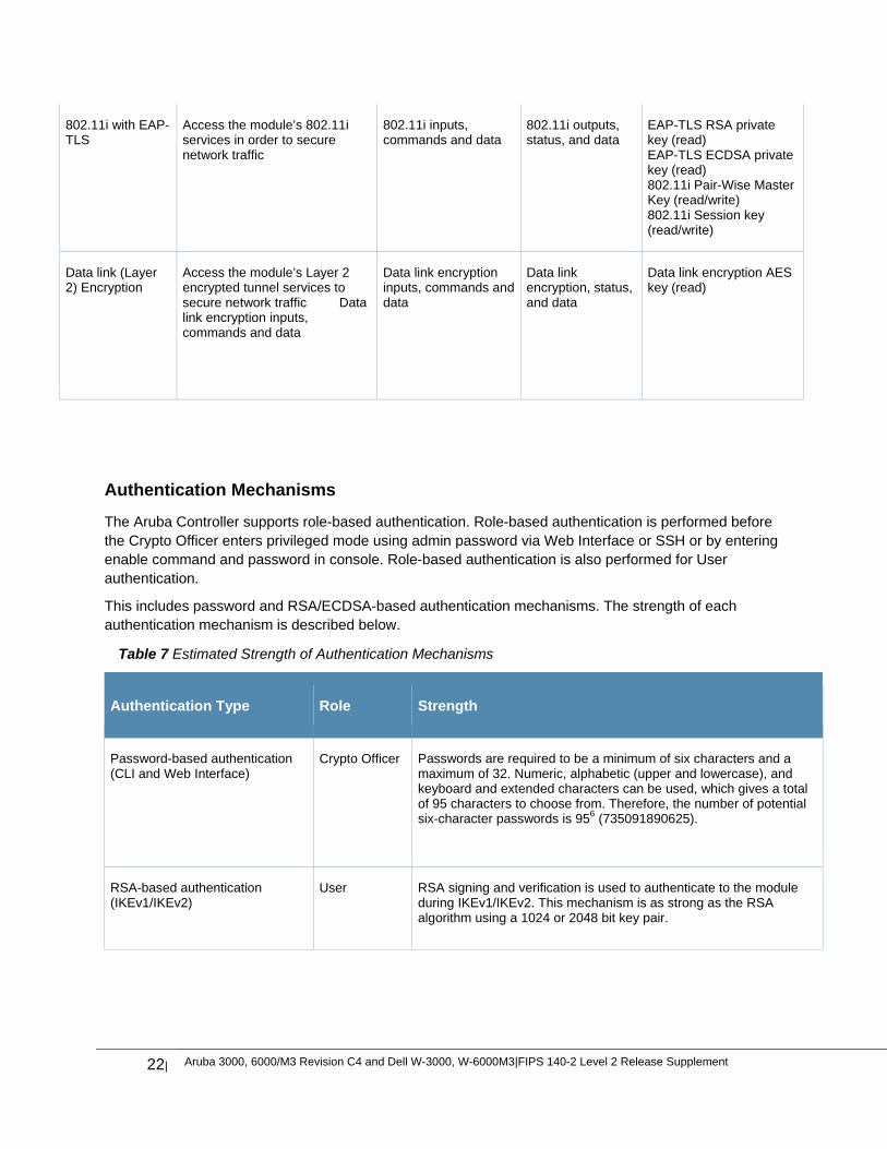
802.11i with EAP-TLS
Access the module’s 802.11i services in order to secure network traffic
802.11i inputs, commands and data
802.11i outputs, status, and data
EAP-TLS RSA private key (read) EAP-TLS ECDSA private key (read) 802.11i Pair-Wise Master Key (read/write) 802.11i Session key (read/write)
Data link (Layer 2) Encryption
Access the module’s Layer 2 encrypted tunnel services to secure network traffic Data link encryption inputs, commands and data
Data link encryption inputs, commands and data
Data link encryption, status, and data
Data link encryption AES key (read)
Authentication Mechanisms
The Aruba Controller supports role-based authentication. Role-based authentication is performed before the Crypto Officer enters privileged mode using admin password via Web Interface or SSH or by entering enable command and password in console. Role-based authentication is also performed for User authentication.
This includes password and RSA/ECDSA-based authentication mechanisms. The strength of each authentication mechanism is described below.
Table 7 Estimated Strength of Authentication Mechanisms
Authentication Type Role Strength
Password-based authentication (CLI and Web Interface)
Crypto Officer Passwords are required to be a minimum of six characters and a maximum of 32. Numeric, alphabetic (upper and lowercase), and keyboard and extended characters can be used, which gives a total of 95 characters to choose from. Therefore, the number of potential six-character passwords is 956 (735091890625).
RSA-based authentication (IKEv1/IKEv2)
User RSA signing and verification is used to authenticate to the module during IKEv1/IKEv2. This mechanism is as strong as the RSA algorithm using a 1024 or 2048 bit key pair.
Aruba 3000, 6000/M3 Revision C4 and Dell W-3000, W-6000M3|FIPS 140-2 Level 2 Release Supplement |23
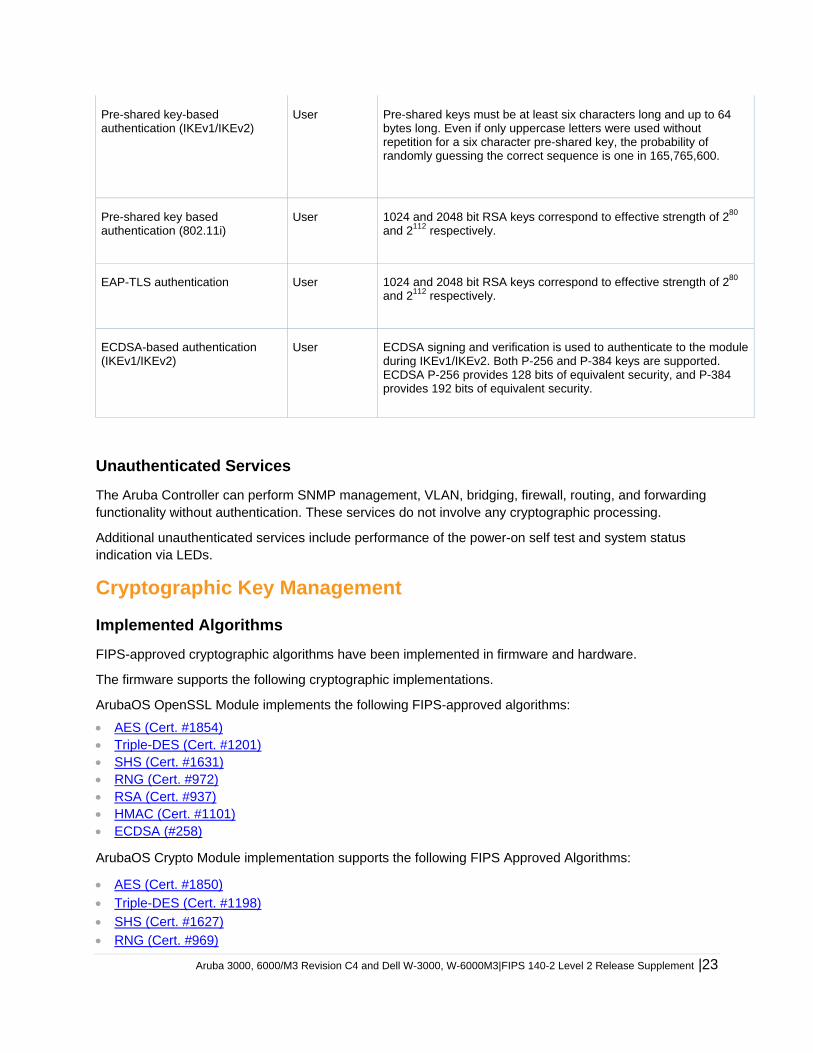
Pre-shared key-based authentication (IKEv1/IKEv2)
User Pre-shared keys must be at least six characters long and up to 64 bytes long. Even if only uppercase letters were used without repetition for a six character pre-shared key, the probability of randomly guessing the correct sequence is one in 165,765,600.
Pre-shared key based authentication (802.11i)
User 1024 and 2048 bit RSA keys correspond to effective strength of 280 and 2112 respectively.
EAP-TLS authentication User 1024 and 2048 bit RSA keys correspond to effective strength of 280 and 2112 respectively.
ECDSA-based authentication (IKEv1/IKEv2)
User ECDSA signing and verification is used to authenticate to the module during IKEv1/IKEv2. Both P-256 and P-384 keys are supported. ECDSA P-256 provides 128 bits of equivalent security, and P-384 provides 192 bits of equivalent security.
Unauthenticated Services
The Aruba Controller can perform SNMP management, VLAN, bridging, firewall, routing, and forwarding functionality without authentication. These services do not involve any cryptographic processing.
Additional unauthenticated services include performance of the power-on self test and system status indication via LEDs.
Cryptographic Key Management
Implemented Algorithms
FIPS-approved cryptographic algorithms have been implemented in firmware and hardware.
The firmware supports the following cryptographic implementations.
ArubaOS OpenSSL Module implements the following FIPS-approved algorithms:
AES (Cert. #1854) Triple-DES (Cert. #1201) SHS (Cert. #1631) RNG (Cert. #972) RSA (Cert. #937) HMAC (Cert. #1101) ECDSA (#258)
ArubaOS Crypto Module implementation supports the following FIPS Approved Algorithms:
AES (Cert. #1850)
Triple-DES (Cert. #1198)
SHS (Cert. #1627)
RNG (Cert. #969)
24| Aruba 3000, 6000/M3 Revision C4 and Dell W-3000, W-6000M3|FIPS 140-2 Level 2 Release Supplement
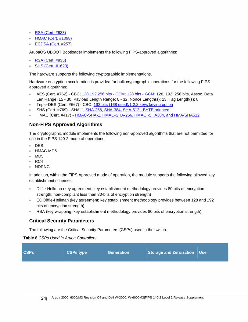
RSA (Cert. #933)
HMAC (Cert. #1098)
ECDSA (Cert. #257)
ArubaOS UBOOT Bootloader implements the following FIPS-approved algorithms:
RSA (Cert. #935)
SHS (Cert. #1629)
The hardware supports the following cryptographic implementations.
Hardware encryption acceleration is provided for bulk cryptographic operations for the following FIPS approved algorithms:
AES (Cert. #762) - CBC; 128,192,256 bits - CCM; 128 bits - GCM; 128, 192, 256 bits, Assoc. Data Len Range: 15 - 30, Payload Length Range: 0 - 32, Nonce Length(s): 13, Tag Length(s): 8
Triple-DES (Cert. #667) - CBC; 192 bits (168 used)/1,2,3 keys keying option SHS (Cert. #769) - SHA-1, SHA-256, SHA-384, SHA-512 - BYTE oriented HMAC (Cert. #417) - HMAC-SHA-1, HMAC-SHA-256, HMAC -SHA384, and HMA-SHA512
Non-FIPS Approved Algorithms
The cryptographic module implements the following non-approved algorithms that are not permitted for use in the FIPS 140-2 mode of operations:
DES HMAC-MD5 MD5 RC4 NDRNG
In addition, within the FIPS Approved mode of operation, the module supports the following allowed key
establishment schemes:
Diffie-Hellman (key agreement; key establishment methodology provides 80 bits of encryption
strength; non-compliant less than 80-bits of encryption strength)
EC Diffie-Hellman (key agreement; key establishment methodology provides between 128 and 192
bits of encryption strength)
RSA (key wrapping; key establishment methodology provides 80 bits of encryption strength)
Critical Security Parameters
The following are the Critical Security Parameters (CSPs) used in the switch.
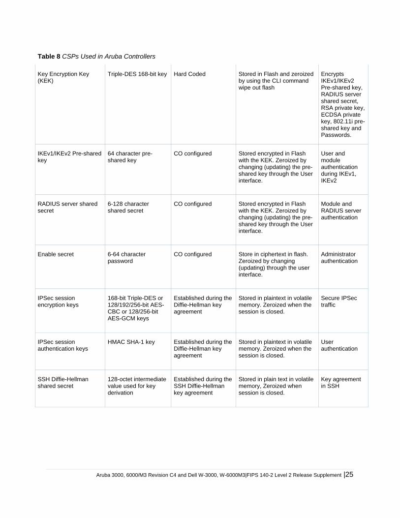
Table 8 CSPs Used in Aruba Controllers
CSPs CSPs type Generation Storage and Zeroization Use
Aruba 3000, 6000/M3 Revision C4 and Dell W-3000, W-6000M3|FIPS 140-2 Level 2 Release Supplement |25
Table 8 CSPs Used in Aruba Controllers
Key Encryption Key (KEK)
Triple-DES 168-bit key Hard Coded Stored in Flash and zeroized by using the CLI command wipe out flash
Encrypts IKEv1/IKEv2 Pre-shared key, RADIUS server shared secret, RSA private key, ECDSA private key, 802.11i pre-shared key and Passwords.
IKEv1/IKEv2 Pre-shared key
64 character pre-shared key
CO configured Stored encrypted in Flash with the KEK. Zeroized by changing (updating) the pre-shared key through the User interface.
User and module authentication during IKEv1, IKEv2
RADIUS server shared secret
6-128 character shared secret
CO configured Stored encrypted in Flash with the KEK. Zeroized by changing (updating) the pre-shared key through the User interface.
Module and RADIUS server authentication
Enable secret 6-64 character password
CO configured Store in ciphertext in flash. Zeroized by changing (updating) through the user interface.
Administrator authentication
IPSec session encryption keys
168-bit Triple-DES or 128/192/256-bit AES-CBC or 128/256-bit AES-GCM keys
Established during the Diffie-Hellman key agreement
Stored in plaintext in volatile memory. Zeroized when the session is closed.
Secure IPSec traffic
IPSec session authentication keys
HMAC SHA-1 key Established during the Diffie-Hellman key agreement
Stored in plaintext in volatile memory. Zeroized when the session is closed.
User authentication
SSH Diffie-Hellman shared secret
128-octet intermediate value used for key derivation
Established during the SSH Diffie-Hellman key agreement
Stored in plain text in volatile memory, Zeroized when session is closed.
Key agreement in SSH
26| Aruba 3000, 6000/M3 Revision C4 and Dell W-3000, W-6000M3|FIPS 140-2 Level 2 Release Supplement
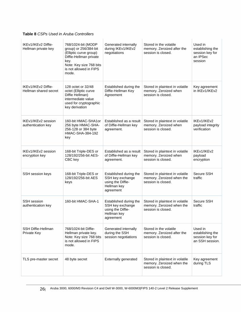
Table 8 CSPs Used in Aruba Controllers
IKEv1/IKEv2 Diffie-Hellman private key
768/1024-bit (MODP group) or 256/384-bit (Elliptic curve group) Diffie-Hellman private key. Note: Key size 768 bits is not allowed in FIPS mode.
Generated internally during IKEv1/IKEv2 negotiations
Stored in the volatile memory. Zeroized after the session is closed.
Used in establishing the session key for an IPSec session
IKEv1/IKEv2 Diffie-Hellman shared secret
128 octet or 32/48 octet (Elliptic curve Diffie Hellman) intermediate value used for cryptographic key derivation
Established during the Diffie-Hellman Key Agreement
Stored in plaintext in volatile memory. Zeroized when session is closed.
Key agreement in IKEv1/IKEv2
IKEv1/IKEv2 session authentication key
160-bit HMAC-SHA1or 256 byte HMAC-SHA-256-128 or 384 byte HMAC-SHA-384-192 key
Established as a result of Diffie-Hellman key agreement.
Stored in plaintext in volatile memory. Zeroized when session is closed.
IKEv1/IKEv2 payload integrity verification
IKEv1/IKEv2 session encryption key
168-bit Triple-DES or 128/192/256-bit AES-CBC key
Established as a result of Diffie-Hellman key agreement.
Stored in plaintext in volatile memory. Zeroized when session is closed.
IKEv1/IKEv2 payload encryption
SSH session keys 168-bit Triple-DES or 128/192/256-bit AES keys
Established during the SSH key exchange using the Diffie-Hellman key agreement
Stored in plaintext in volatile memory. Zeroized when the session is closed.
Secure SSH traffic
SSH session authentication key
160-bit HMAC-SHA-1 Established during the SSH key exchange using the Diffie-Hellman key agreement
Stored in plaintext in volatile memory. Zeroized when the session is closed.
Secure SSH traffic
SSH Diffie-Hellman Private Key
768/1024-bit Diffie-Hellman private key. Note: Key size 768 bits is not allowed in FIPS mode.
Generated internally during the SSH session negotiations
Stored in the volatile memory. Zeroized after the session is closed.
Used in establishing the session key for an SSH session.
TLS pre-master secret 48 byte secret Externally generated Stored in plaintext in volatile memory. Zeroized when the session is closed.
Key agreement during TLS
Aruba 3000, 6000/M3 Revision C4 and Dell W-3000, W-6000M3|FIPS 140-2 Level 2 Release Supplement |27
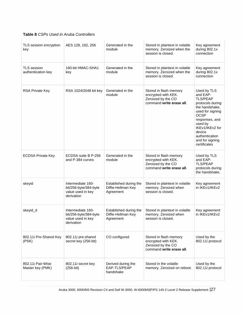
Table 8 CSPs Used in Aruba Controllers
TLS session encryption key
AES 128, 192, 256 Generated in the module
Stored in plaintext in volatile memory. Zeroized when the session is closed.
Key agreement during 802.1x connection
TLS session authentication key
160-bit HMAC-SHA1 key
Generated in the module
Stored in plaintext in volatile memory. Zeroized when the session is closed.
Key agreement during 802.1x connection
RSA Private Key RSA 1024/2048 bit key Generated in the module
Stored in flash memory encrypted with KEK. Zeroized by the CO command write erase all.
Used by TLS and EAP-TLS/PEAP protocols during the handshake, used for signing OCSP responses, and used by IKEv1/IKEv2 for device authentication and for signing certificates
ECDSA Private Key ECDSA suite B P-256 and P-384 curves
Generated in the module
Stored in flash memory encrypted with KEK. Zeroized by the CO command write erase all.
Used by TLS and EAP-TLS/PEAP protocols during the handshake.
skeyid Intermediate 160-bit/256-byte/384-byte value used in key derivation
Established during the Diffie-Hellman Key Agreement
Stored in plaintext in volatile memory. Zeroized when session is closed.
Key agreement in IKEv1/IKEv2
skeyid_d Intermediate 160-bit/256-byte/384-byte value used in key derivation
Established during the Diffie-Hellman Key Agreement
Stored in plaintext in volatile memory. Zeroized when session is closed.
Key agreement in IKEv1/IKEv2
802.11i Pre-Shared Key (PSK)
802.11i pre-shared secret key (256-bit)
CO configured Stored in flash memory encrypted with KEK. Zeroized by the CO command write erase all.
Used by the 802.11i protocol
802.11i Pair-Wise Master key (PMK)
802.11i secret key (256-bit)
Derived during the EAP-TLS/PEAP handshake
Stored in the volatile memory. Zeroized on reboot.
Used by the 802.11i protocol
28| Aruba 3000, 6000/M3 Revision C4 and Dell W-3000, W-6000M3|FIPS 140-2 Level 2 Release Supplement
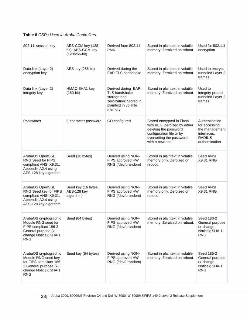
Table 8 CSPs Used in Aruba Controllers
802.11i session key AES-CCM key (128 bit), AES-GCM key (128/256-bit)
Derived from 802.11 PMK
Stored in plaintext in volatile memory. Zeroized on reboot.
Used for 802.11i encryption
Data link (Layer 2) encryption key
AES key (256 bit) Derived during the EAP-TLS handshake
Stored in plaintext in volatile memory. Zeroized on reboot.
Used to encrypt tunneled Layer 2 frames
Data link (Layer 2) integrity key
HMAC-SHA1 key (160-bit)
Derived during EAP-TLS handshake storage and zeroization: Stored in plaintext in volatile memory
Stored in plaintext in volatile memory. Zeroized on reboot.
Used to integrity-protect tunneled Layer 2 frames
Passwords 6-character password CO configured Stored encrypted in Flash with KEK. Zeroized by either deleting the password configuration file or by overwriting the password with a new one.
Authentication for accessing the management interfaces, RADIUS authentication
ArubaOS OpenSSL RNG Seed for FIPS compliant ANSI X9.31, Appendix A2.4 using AES-128 key algorithm
Seed (16 bytes) Derived using NON-FIPS approved HW RNG (/dev/urandom)
Stored in plaintext in volatile memory only. Zeroized on reboot.
Seed ANSI X9.31 RNG
ArubaOS OpenSSL RNG Seed key for FIPS compliant ANSI X9.31, Appendix A2.4 using AES-128 key algorithm
Seed key (16 bytes, AES-128 key algorithm)
Derived using NON-FIPS approved HW RNG (/dev/urandom)
Stored in plaintext in volatile memory only. Zeroized on reboot.
Seed ANSI X9.31 RNG
ArubaOS cryptographic Module RNG seed for FIPS compliant 186-2 General purpose (x-change Notice); SHA-1 RNG
Seed (64 bytes) Derived using NON-FIPS approved HW RNG (/dev/urandom)
Stored in plaintext in volatile memory. Zeroized on reboot.
Seed 186-2 General purpose (x-change Notice); SHA-1 RNG
ArubaOS cryptographic Module RNG seed key for FIPS compliant 186-2 General purpose (x-change Notice); SHA-1 RNG
Seed key (64 bytes) Derived using NON-FIPS approved HW RNG (/dev/urandom)
Stored in plaintext in volatile memory. Zeroized on reboot.
Seed 186-2 General purpose (x-change Notice); SHA-1 RNG
Aruba 3000, 6000/M3 Revision C4 and Dell W-3000, W-6000M3|FIPS 140-2 Level 2 Release Supplement |29
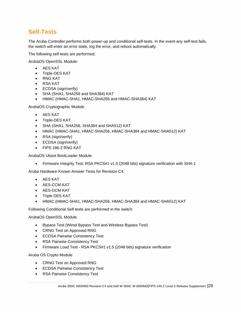
Self-Tests
The Aruba Controller performs both power-up and conditional self-tests. In the event any self-test fails, the switch will enter an error state, log the error, and reboot automatically.
The following self-tests are performed:
ArubaOS OpenSSL Module:
AES KAT Triple-DES KAT RNG KAT RSA KAT ECDSA (sign/verify) SHA (SHA1, SHA256 and SHA384) KAT HMAC (HMAC-SHA1, HMAC-SHA256 and HMAC-SHA384) KAT
ArubaOS Cryptographic Module
AES KAT
Triple-DES KAT
SHA (SHA1, SHA256, SHA384 and SHA512) KAT
HMAC (HMAC-SHA1, HMAC-SHA256, HMAC-SHA384 and HMAC-SHA512) KAT
RSA (sign/verify)
ECDSA (sign/verify)
FIPS 186-2 RNG KAT
ArubaOS Uboot BootLoader Module
Firmware Integrity Test: RSA PKCS#1 v1.5 (2048 bits) signature verification with SHA-1
Aruba Hardware Known Answer Tests for Revision C4:
AES KAT
AES-CCM KAT
AES-GCM KAT
Triple DES KAT
HMAC (HMAC-SHA1, HMAC-SHA256, HMAC-SHA384 and HMAC-SHA512) KAT
Following Conditional Self-tests are performed in the switch:
ArubaOS OpenSSL Module
Bypass Test (Wired Bypass Test and Wireless Bypass Test)
CRNG Test on Approved RNG
ECDSA Pairwise Consistency Test
RSA Pairwise Consistency Test
Firmware Load Test - RSA PKCS#1 v1.5 (2048 bits) signature verification
Aruba OS Crypto Module
CRNG Test on Approved RNG
ECDSA Pairwise Consistency Test
RSA Pairwise Consistency Test
30| Aruba 3000, 6000/M3 Revision C4 and Dell W-3000, W-6000M3|FIPS 140-2 Level 2 Release Supplement
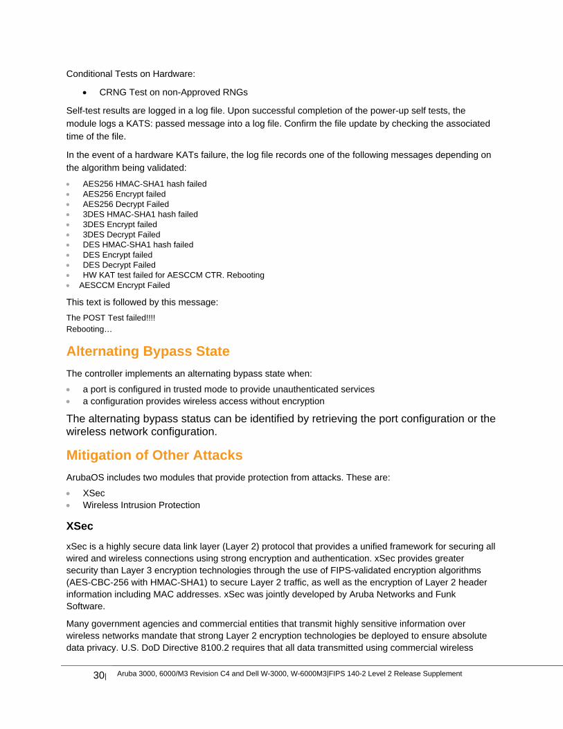
Conditional Tests on Hardware:
CRNG Test on non-Approved RNGs
Self-test results are logged in a log file. Upon successful completion of the power-up self tests, the
module logs a KATS: passed message into a log file. Confirm the file update by checking the associated
time of the file.
In the event of a hardware KATs failure, the log file records one of the following messages depending on
the algorithm being validated:
AES256 HMAC-SHA1 hash failed AES256 Encrypt failed AES256 Decrypt Failed 3DES HMAC-SHA1 hash failed 3DES Encrypt failed 3DES Decrypt Failed DES HMAC-SHA1 hash failed DES Encrypt failed DES Decrypt Failed HW KAT test failed for AESCCM CTR. Rebooting AESCCM Encrypt Failed
This text is followed by this message:
The POST Test failed!!!! Rebooting…
Alternating Bypass State
The controller implements an alternating bypass state when:
a port is configured in trusted mode to provide unauthenticated services a configuration provides wireless access without encryption
The alternating bypass status can be identified by retrieving the port configuration or the wireless network configuration.
Mitigation of Other Attacks
ArubaOS includes two modules that provide protection from attacks. These are:
XSec Wireless Intrusion Protection
XSec
xSec is a highly secure data link layer (Layer 2) protocol that provides a unified framework for securing all wired and wireless connections using strong encryption and authentication. xSec provides greater security than Layer 3 encryption technologies through the use of FIPS-validated encryption algorithms (AES-CBC-256 with HMAC-SHA1) to secure Layer 2 traffic, as well as the encryption of Layer 2 header information including MAC addresses. xSec was jointly developed by Aruba Networks and Funk Software.
Many government agencies and commercial entities that transmit highly sensitive information over wireless networks mandate that strong Layer 2 encryption technologies be deployed to ensure absolute data privacy. U.S. DoD Directive 8100.2 requires that all data transmitted using commercial wireless
Aruba 3000, 6000/M3 Revision C4 and Dell W-3000, W-6000M3|FIPS 140-2 Level 2 Release Supplement |31
devices be encrypted at Layer 2 or Layer 3. The U.S. Navy and Army are requiring Layer 2 encryption, and cryptographic engines used for all sensitive government communications must be validated as meeting FIPS 140-2 requirements.
xSec has been designed to address this requirement and to provide a number of additional benefits.
Wireless Intrusion Detection
Aruba’s Wireless Intrusion Protection (WIP) module eliminates the need for a separate system of RF sensors and security appliances. The WIP module provides extraordinary capabilities to Aruba’s enterprise mobility system, giving administrators visibility into the network, along with the power to thwart malicious wireless attacks, impersonations and unauthorized intrusions.
Wireless intrusion detection is only the first step in securing the corporate environment from unwanted wireless access. Without adequate measures to quickly shut down intrusions, detection is almost worthless. Without accurate classification of APs and stations (e.g., valid, rogue, or neighbor), providing an automated response to possible intrusion is impossible.
Aruba access points constantly scan all channels of the RF spectrum, capturing all 802.11 traffic and locally examining the captured data. Only policy violations are sent to the central controller to ensure minimal impact on wired network performance. While scanning the environment, the Aruba system learns about all wireless APs and stations and classifies these devices based on traffic flows seen on the wire and in the air. This traffic is collected and correlated on the controller.
Aruba’s WIP module provides both detection and prevention capabilities. Users and devices are detected and classified so administrators can react to both unintentional and malicious WLAN access. No other system on the market provides such capabilities.
Unique Station and User Classification
Aruba’s patent-pending classification system automatically identifies and classifies all APs and stations connected to the network. The system works by comparing traffic seen in the air with traffic seen on the wire. When a match is found, it is known with certainty that the device belongs to the local network rather than a neighboring network. This avoids false alarms for the administrator, because only true rogue devices are classified as such.
Detecting and Disabling Rogue APs
Aruba’s classification algorithms allow the system to accurately determine who is a threat and who is not. Once classified as rogue, these APs can be automatically disabled. Administrators are also notified of the presence of rogue devices, along with their precise physical location on a floor plan, so that they may be removed from the network.
Denial of Service and Impersonation Protection
Wireless networks, by their nature, make an attractive target for denial of service attacks. Such attacks include software that floods the network with association requests, attacks that make a laptop look like thousands of APs, and deauthentication floods. Aruba controllers equipped with the Aruba WIP module maintain signatures of many different wireless attacks and are able to block them so service is not disrupted.
Advanced Denial of Service (DoS) protection keeps enterprises safe against a variety of wireless attacks, including association and de-authentication floods, honeypots and AP and station impersonations. Based
32| Aruba 3000, 6000/M3 Revision C4 and Dell W-3000, W-6000M3|FIPS 140-2 Level 2 Release Supplement
on location signatures and client classification, Aruba access points will drop illegal requests and generate alerts to notify administrators of the attack.
Man-in-the-Middle Protection
One of the common attacks possible in wireless networks is the “man-in-the-middle” attack. During a man-in-the-middle attack, a hacker masquerades as a legitimate AP. Then, acting as a relay point, this man-in-the-middle fools users and other APs into sending data through the unauthorized device. An attacker can then modify or corrupt data or conduct password-cracking routines.
Aruba access points monitor the air to detect other wireless stations masquerading as valid APs. When such masquerading is detected, appropriate defense mechanisms are put into place. Aruba controllers also track unique “signatures” for each wireless client in the network. If a new station is introduced claiming to be a particular client, but without the proper signature, a station impersonation attack is detected.
Policy Definition and Enforcement
Aruba WIP provides a number of policies that can be configured to take automatic action when a policy is violated. Examples of wireless policies include weak WEP implementation detection, AP misconfiguration protection, ad-hoc network detection and protection, unauthorized NIC type detection, wireless bridge detection and more.
Using Wireless to Protect your Wired Network
Even if wireless LANs are not sanctioned at this time, no security conscious company can afford to do nothing. Aruba’s WIP will keep wireless traffic from working its way into the wired network through rogue APs unknowingly attached to a network port. With Aruba’s mobility system equipped with WIP, the enterprise network is protected against wireless security holes. And when the enterprise is ready to deploy wireless LANs, the Aruba system can be easily reconfigured to provide a scalable and secure wireless LAN infrastructure.
Using Wireless to Protect your Existing Wireless Network
Aruba’s mobility system with WIP delivers the detection and protection necessary to keep your existing wireless network safe from undesirable wireless access. ArubaOS WIP complements and enhances any existing WLAN deployment, including Cisco deployments, by providing advanced RF security and control features not found in first-generation wireless products.
Aruba 3000, 6000/M3 Revision C4 and Dell W-3000, W-6000M3|FIPS 140-2 Level 2 Release Supplement |33
Installing the Controller
This chapter covers the physical installation of the Aruba 3000 and 6000/M3 Controllers with FIPS 140-2 Level 2 validation. The Crypto Officer is responsible for ensuring that the following procedures are used to place the switch in a FIPS-approved mode of operation.
This chapter covers the following installation topics:
Precautions to be observed during installation Requirements for the switch components and rack mounting gear Selecting a proper environment for the switch Mounting the switch in a rack Connecting power to the switch
Pre-Installation Checklist
You will need the following during installation:
Aruba 3000 and 6000/M3 Controller components. Aruba 3000 and 6000/M3 rack mounting kit. Phillips or cross-head screwdriver. 19-inch equipment rack or equivalent. 3U rack space for the Aruba 6000-400 and 1U rack space for the Aruba 3000-Series with 10 cm (4 inches) clearance
to the left, right, front, and rear of the rack. Another person to help position the switch. Aruba power cord for each power supply, rated to at least 10 A with IEC320 connector. Adequate power supplies and electrical power. Cool, non-condensing air 0 to 40 ºC (32 to 104 ºF). May require air conditioning. Management Station (PC) with 10/100 Mbps Ethernet port and SSH software. A 4- or 8-conductor Category 5 UTP Ethernet cable.
Precautions Installation should be performed only by a trained technician. Dangerous voltage in excess of 240 VAC is always present while the Aruba power supply is plugged into an electrical
outlet. Remove all rings, jewelry, and other potentially conductive material before working with this product. Never insert foreign objects into the chassis, the power supply, or any other component, even when the power
supplies have been turned off, unplugged, or removed. Main power is fully disconnected from the switch only by unplugging all power cords from their power outlets. For
safety reasons, make sure the power outlets and plugs are within easy reach of the operator. Do not handle electrical cables that are not insulated. This includes any network cables. Keep water and other fluids away from the product. Comply with electrical grounding standards during all phases of installation and operation of the product. Do not allow
the switch chassis, network ports, power supplies, or mounting brackets to contact any device, cable, object, or person attached to a different electrical ground. Also, never connect the device to external storm grounding sources.
Installation or removal of the chassis or any module must be performed in a static-free environment. The proper use of anti-static body straps and mats is strongly recommended.
Keep modules in anti-static packaging when not installed in the chassis.
34| Aruba 3000, 6000/M3 Revision C4 and Dell W-3000, W-6000M3|FIPS 140-2 Level 2 Release Supplement
Do not ship or store this product near strong electromagnetic, electrostatic, magnetic or radioactive fields.
Do not disassemble chassis or modules. They have no internal user-serviceable parts. When service or repair is needed, contact Aruba Networks.
Product Examination
The units are shipped to the Crypto Officer in factory-sealed boxes using trusted commercial carrier shipping companies. The Crypto Officer should examine the carton for evidence of tampering. Tamper-evidence includes tears, scratches, and other irregularities in the packaging.
Package Contents
The product carton should include the following:
Aruba 3000 and 6000/M3 Controller Rack mounting kit Aruba User Documentation CD Tamper-Evident Labels
Minimum Configuration for the Aruba 6000-400
The Aruba 6000-400 controller chassis must include the following basic components:
One modular switch chassis One fan tray One Aruba M3mk1-S-F1 card in slot 0 Power Supply
The number and type of power supplies required depends on the number of line
cards installed in the chassis (refer to the Aruba 6000 Mobility Controller Installation
Guide). It is the Crypto Office's responsibility to install all required power supplies
during module setup phase.
The switch is shipped with all required modules installed.
The Aruba 3000 series do not have minimum configurations, as they are fixed
configuration chassis.
Aruba 3000, 6000/M3 Revision C4 and Dell W-3000, W-6000M3|FIPS 140-2 Level 2 Release Supplement |35
Tamper-Evident Labels
After testing, the Crypto Officer must apply Tamper-Evident Labels (TELs) to the switch. When applied properly, the TELs allow the Crypto Officer to detect the opening of the chassis cover, the removal or replacement of modules or cover plates, or physical access to restricted ports. Vendor provides FIPS 140 designated TELs which have met the physical security testing requirements for tamper evident labels under the FIPS 140-2 Standard. TELs are not endorsed by the Cryptographic Module Validation Program (CMVP).
The tamper-evident labels shall be installed for the module to operate in a FIPS
Approved mode of operation.
Aruba Provides double the required amount of TELs. If a customer requires
replacement TELs, please call customer support and Aruba will provide the TELs
(Part # 4010061-01).
The Crypto officer shall be responsible for keeping the extra TELs at a safe location
and managing the use of the TELs.
Reading TELs
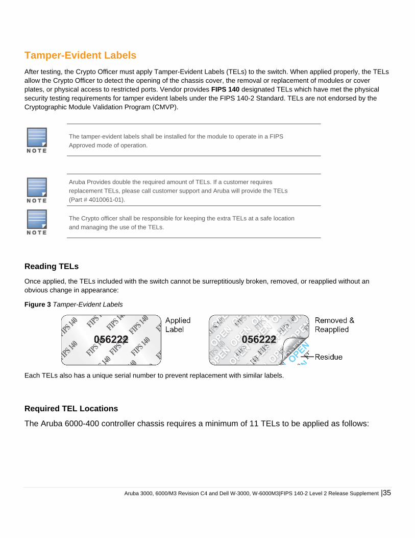
Once applied, the TELs included with the switch cannot be surreptitiously broken, removed, or reapplied without an obvious change in appearance:
Figure 3 Tamper-Evident Labels
Each TELs also has a unique serial number to prevent replacement with similar labels.
Required TEL Locations
The Aruba 6000-400 controller chassis requires a minimum of 11 TELs to be applied as follows:
36| Aruba 3000, 6000/M3 Revision C4 and Dell W-3000, W-6000M3|FIPS 140-2 Level 2 Release Supplement
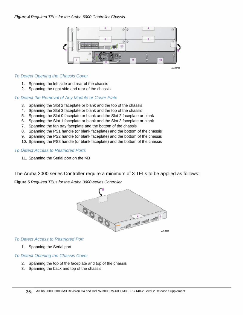
Figure 4 Required TELs for the Aruba 6000 Controller Chassis
To Detect Opening the Chassis Cover
1. Spanning the left side and rear of the chassis 2. Spanning the right side and rear of the chassis
To Detect the Removal of Any Module or Cover Plate
3. Spanning the Slot 2 faceplate or blank and the top of the chassis 4. Spanning the Slot 3 faceplate or blank and the top of the chassis 5. Spanning the Slot 0 faceplate or blank and the Slot 2 faceplate or blank 6. Spanning the Slot 1 faceplate or blank and the Slot 3 faceplate or blank 7. Spanning the fan tray faceplate and the bottom of the chassis 8. Spanning the PS1 handle (or blank faceplate) and the bottom of the chassis 9. Spanning the PS2 handle (or blank faceplate) and the bottom of the chassis 10. Spanning the PS3 handle (or blank faceplate) and the bottom of the chassis
To Detect Access to Restricted Ports
11. Spanning the Serial port on the M3
The Aruba 3000 series Controller require a minimum of 3 TELs to be applied as follows:
Figure 5 Required TELs for the Aruba 3000-series Controller
To Detect Access to Restricted Port
1. Spanning the Serial port
To Detect Opening the Chassis Cover
2. Spanning the top of the faceplate and top of the chassis 3. Spanning the back and top of the chassis
Aruba 3000, 6000/M3 Revision C4 and Dell W-3000, W-6000M3|FIPS 140-2 Level 2 Release Supplement |37
Applying TELs
The Crypto Officer should employ TELs as follows:
Before applying a TEL, make sure the target surfaces are clean and dry. Do not cut, trim, punch, or otherwise alter the TEL. Apply the wholly intact TEL firmly and completely to the target surfaces. Ensure that TEL placement is not defeated by simultaneous removal of multiple modules. Allow 24 hours for the TEL adhesive seal to completely cure. Record the position and serial number of each applied TEL in a security log.
Once the TELs are applied, the Crypto Officer (CO) should perform initial setup and configuration as described in the next chapter.
38| Aruba 3000, 6000/M3 Revision C4 and Dell W-3000, W-6000M3|FIPS 140-2 Level 2 Release Supplement
Ongoing Management
The Aruba 3000 and 6000/M3 Controllers meet FIPS 140-2 Level 2 requirements. The information below describe how to keep the switch in FIPS-approved mode of operation. The Crypto Officer must ensure that the switch is kept in a FIPS-approved mode of operation.
Crypto Officer Management
The Crypto Officer must ensure that the switch is always operating in a FIPS-approved mode of operation. This can be achieved by ensuring the following:
FIPS mode must be enabled on the switch before Users are permitted to use the switch (see “Enabling FIPS Mode” on page 37)
The admin role must be root. Passwords must be at least six characters long. VPN services can only be provided by IPsec or L2TP over IPsec. Access to the switch Web Interface is permitted only using HTTPS over a TLS tunnel. Basic HTTP and HTTPS over
SSL are not permitted. Only SNMP read-only may be enabled. Only FIPS-approved algorithms can be used for cryptographic services (such as HTTPS, L2, AES-CBC, SSH, and
IKEv1/IKEv2-IPSec), which include AES, Triple-DES, SHA-1, HMAC SHA-1, and RSA signature and verification. TFTP can only be used to load backup and restore files. These files are: Configuration files (system setup
configuration), the WMS database (radio network configuration), and log files. (FTP and TFTP over IPsec can be used to transfer configuration files.)
The switch logs must be monitored. If a strange activity is found, the Crypto Officer should take the switch off line and investigate.
The Tamper-Evident Labels (TELs) must be regularly examined for signs of tampering. When installing expansion or replacement modules for the Aruba 6000-400, use only FIPS-approved modules,
replace TELs affected by the change, and record the reason for the change, along with the new TEL locations and serial numbers, in the security log.
The Crypto Officer shall not configure the Diffie-Hellman algorithm with 768-bits (Group 1) in FIPS mode for IKEv1/IKEv2-IPSec and SSH.
User Guidance
The User accesses the switch VPN functionality as an IPsec client. The user can also access the switch 802.11i functionality as an 802.11 client. Although outside the boundary of the switch, the User should be directed to be careful not to provide authentication information and session keys to others parties.
Aruba 3000, 6000/M3 Revision C4 and Dell W-3000, W-6000M3|FIPS 140-2 Level 2 Release Supplement |39
Setup and Configuration
The Aruba 3000 and 6000/M3 Controllers meet FIPS 140-2 Level 2 requirements. The sections below describe how to place and keep the switch in FIPS-approved mode of operation. The Crypto Officer (CO) must ensure that the switch is kept in a FIPS-approved mode of operation.
The switch can operate in two modes: the FIPS-approved mode, and the standard non-FIPS mode. By default, the switch operates in non-FIPS mode.
Setting Up Your Controller
To set up your controller:
1. Make sure that the controller is not connected to any device on your network. 2. Boot up the controller. 3. Connect your PC or workstation to a line port on the controller.
For further details, see the ArubaOS 6.1 Quick Start Guide.
Enabling FIPS Mode
For FIPS compliance, users cannot be allowed to access the switch until the CO changes the mode of operation to FIPS mode. There are two ways to enable FIPS mode:
Use the WebUI Use the Setup Wizard
Enabling FIPS with the Setup Wizard
The Setup Wizard allows you to configure access to the controller, install software licenses, and configure wireless local area networks (WLANs) for internal or guest users.
The Setup Wizard is available the first time you connect to and log into the controller or whenever the controller is reset to its factory default configuration. After you complete the Setup Wizard, the controller reboots using the new configuration information you entered.
For details on running the Setup Wizard, see the ArubaOS 6.1 Quick Start Guide.
Enabling FIPS with the WebUI
The default IP address of the controller is 172.16.0.254. When you connect a PC or workstation to a line port on the controller, you can connect to this IP address through a Web browser. The system must be configured to either obtain its IP address via DHCP or have a static IP address on the 172.16.0.0/24 subnetwork.
To log in with the WebUI:
1. Open a Web browser and connect to http://172.16.0.254. 2. Log in. 3. Go to the Configuration > Network > Controller > System Settings page (the default page when you click the
Configuration tab). 4. Click the FIPS Mode for Controller Enable checkbox.
40| Aruba 3000, 6000/M3 Revision C4 and Dell W-3000, W-6000M3|FIPS 140-2 Level 2 Release Supplement
If you need to enable FIPS mode on a controller that is no longer in the factory default configuration, you can either:
Log in through the WebUI as described previously Enable FIPS on the Configuration > Wizards > Controller Wizard page ‘FIPS Enable’ is shown on SSH Command Line Interface (CLI) after issuing the command show fips.
Disallowed FIPS Mode Configurations
When you enable FIPS mode, the following configuration options are disallowed:
All WEP features WPA TKIP mixed mode Any combination of DES, MD5, and PPTP


![Aruba Networks - cyber.gov.au · [MIB] ArubaOS 6.3 MIB Reference Guide, Ref 0511323-01 [FIPS] Aruba 600/3000/6000/7200 FIPS 140-2 Security Policy . Aruba Networks Security Target](https://img.pdfslide.net/doc/110x75/5ea29c799d065e039132c511/aruba-networks-cybergovau-mib-arubaos-63-mib-reference-guide-ref-0511323-01.jpg)