Embed Size (px)
Citation preview
Document Ref: SX018a-EN-EU Sheet 1 of 21
Title
Example: Column splice - non-bearing splice
Eurocode Ref EN 1993-1-8, EN1993-1-1Made by Edurne Nunez Date Mar 2005
CALCULATION SHEET
Checked by Abdul Malik Date Mar 2006
Example: Column splice - non-bearing splice
This example presents a method for verifying the adequacy of a non-bearing column splice using bolted flange and web cover plates. The design forces on the cover plates are determined from the axial load on the column, the nominal moments and shear forces. The design resistances of the cover plates and the bolt groups are then determined. The example also demonstrates the calculation of the tensile tying resistance of the splice for structural integrity.
1 Column Splice Design Resistance This example presents full details and procedures for each of the possible design checks; it also includes diagrams both for the notations and for the dimensions. In practice the presentation would normally be much shorter.
Design procedures are in accordance with guidance in SN023.
Table 1 gives the Section number in this example where the procedure for calculating the design resistance is presented. In Section 13, a summary of the values for design resistances and critical mode of failure are given.
SN023
Table 1: Design resistance of a non-bearing column splice
Mode of failure Section Design Resistance
Flange cover plate compression tension
7 NRd,fp,c
NRd,fp,t
Flange cover plate bolt group 8 VRd,fp
Web cover plate 9 NRd,wp,c
Web cover plate bolt group 10 VRd,wp
Column web bolt group 11 VRd,w
Structural integrity of the splice (under tying force)
12 NRd,u
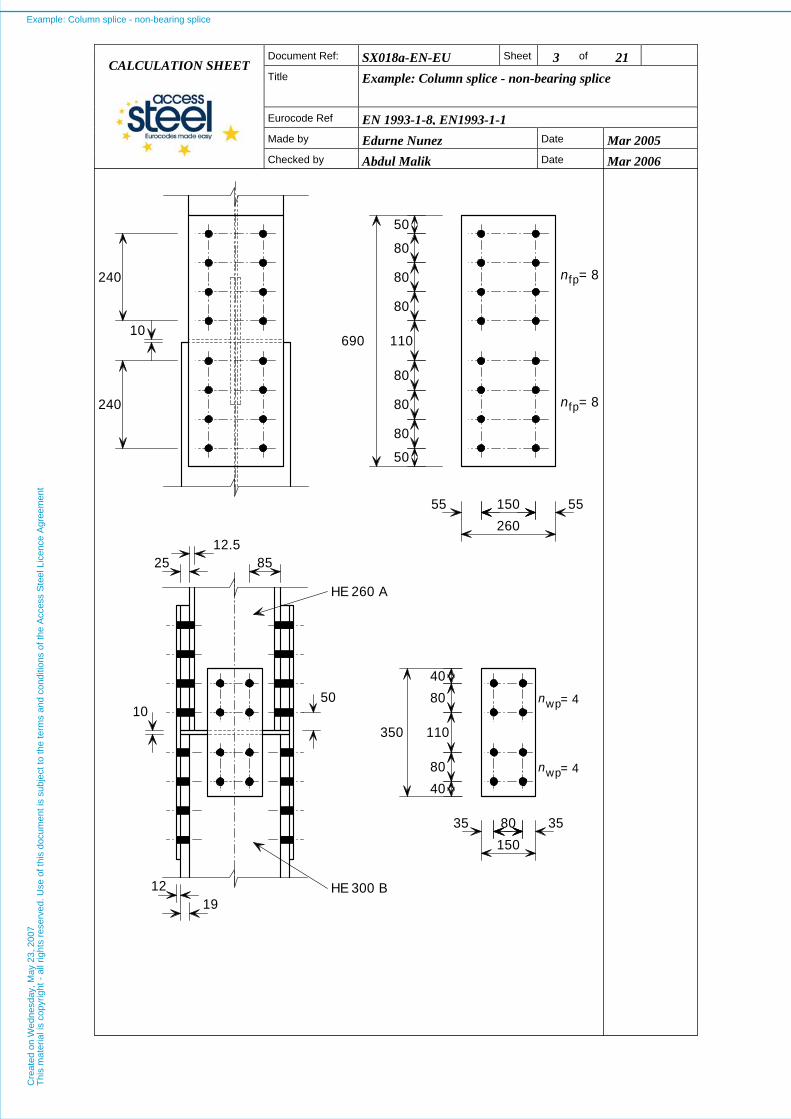
2 Column Splice Details The details of the column splice are based on guidance for initial sizing given in SN024 and are shown in the Figures below.
The hole positions for bolts comply with minimum and maximum spacing, end and edge distance requirements of §3.5 of EN1993-1-8.
EN1993-1-8 §3.5
Example: Column splice - non-bearing spliceC
reat
ed o
n W
edne
sday
, May
23,
200
7T
his
mat
eria
l is
copy
right
- a
ll rig
hts
rese
rved
. Use
of t
his
docu
men
t is
subj
ect t
o th
e te
rms
and
cond
ition
s of
the
Acc
ess
Ste
el L
icen
ce A
gree
men
t

SX018a-EN-EU Sheet 2 of 21 Document Ref:
Title
Example: Column splice - non-bearing splice CALCULATION SHEET
Eurocode Ref EN 1993-1-8, EN1993-1-1Made by Edurne Nunez Date Mar 2005
Checked by Abdul Malik Date Mar 2006
Column splice - Details
1,fp
1,fp
1,fp
1,fp
1,fp
1,fp
1,fp
fp
2,fp
fp
2,fp 2,fpb
p
p
p
p
p
p
p
e
pe e
h
= 8
= 8
n
n
fp
fp
jL
jL
gv 1,fp,j
1,wp
1,wp
1,wp
2,wp 2,wpwp
fp
wp
e
p
p
p
e ep
b
tt
t
h
2,wp
e 1,w
gv
n
n
wp= 4
= 4wp
f,uc
f,lc
t pae 2,w
1,wp,j
Example: Column splice - non-bearing spliceC
reat
ed o
n W
edne
sday
, May
23,
200
7T
his
mat
eria
l is
copy
right
- a
ll rig
hts
rese
rved
. Use
of t
his
docu
men
t is
subj
ect t
o th
e te
rms
and
cond
ition
s of
the
Acc
ess
Ste
el L
icen
ce A
gree
men
t
SX018a-EN-EU Sheet 3 of 21 Document Ref:
Title
Example: Column splice - non-bearing splice CALCULATION SHEET
Eurocode Ref EN 1993-1-8, EN1993-1-1Made by Edurne Nunez Date Mar 2005
Checked by Abdul Malik Date Mar 2006
n
n
fp
fp
n
n
= 8
= 8
= 4
= 4
wp
wp
690
80
80
80
80
80
80
80
80
12.525
1050
1912
350
50
50
110
15055 55260
40
110
40
80150
35 35
85
240
240
10
HE 300 B
HE 260 A
Example: Column splice - non-bearing spliceC
reat
ed o
n W
edne
sday
, May
23,
200
7T
his
mat
eria
l is
copy
right
- a
ll rig
hts
rese
rved
. Use
of t
his
docu
men
t is
subj
ect t
o th
e te
rms
and
cond
ition
s of
the
Acc
ess
Ste
el L
icen
ce A
gree
men
t
Document Ref: SX018a-EN-EU Sheet 4 of 21
Title
Example: Column splice - non-bearing splice
Eurocode Ref EN 1993-1-8, EN1993-1-1Made by Edurne Nunez Date Mar 2005
CALCULATION SHEET
Checked by Abdul Malik Date Mar 2006
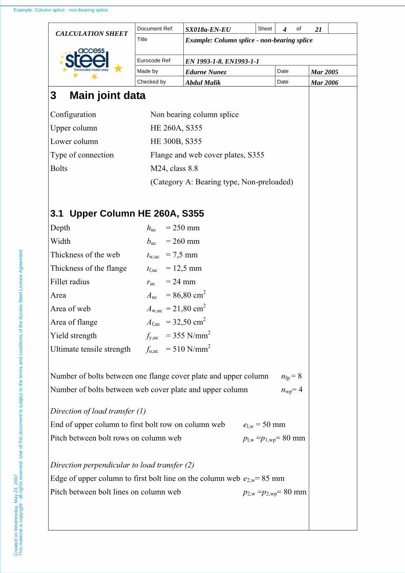
3 Main joint data Configuration Non bearing column splice
Upper column HE 260A, S355
Lower column HE 300B, S355
Type of connection Flange and web cover plates, S355
Bolts M24, class 8.8
(Category A: Bearing type, Non-preloaded)
3.1 Upper Column HE 260A, S355 Depth huc = 250 mm
Width buc = 260 mm
Thickness of the web tw,uc = 7,5 mm
Thickness of the flange tf,uc = 12,5 mm
Fillet radius ruc = 24 mm
Area Auc = 86,80 cm2
Area of web Aw,uc = 21,80 cm2
Area of flange Af,uc = 32,50 cm2
Yield strength fy,uc = 355 N/mm2
Ultimate tensile strength fu,uc = 510 N/mm2
Number of bolts between one flange cover plate and upper column nfp = 8
Number of bolts between web cover plate and upper column nwp= 4
Direction of load transfer (1)
End of upper column to first bolt row on column web el,w = 50 mm
Pitch between bolt rows on column web pl,w =p1,wp= 80 mm
Direction perpendicular to load transfer (2)
Edge of upper column to first bolt line on the column web e2,w= 85 mm
Pitch between bolt lines on column web p2,w =p2,wp= 80 mm
Example: Column splice - non-bearing spliceC
reat
ed o
n W
edne
sday
, May
23,
200
7T
his
mat
eria
l is
copy
right
- a
ll rig
hts
rese
rved
. Use
of t
his
docu
men
t is
subj
ect t
o th
e te
rms
and
cond
ition
s of
the
Acc
ess
Ste
el L
icen
ce A
gree
men
t

Document Ref: SX018a-EN-EU Sheet 5 of 21
Title
Example: Column splice - non-bearing splice
Eurocode Ref EN 1993-1-8, EN1993-1-1Made by Edurne Nunez Date Mar 2005
CALCULATION SHEET
Checked by Abdul Malik Date Mar 2006
3.2 Lower Column HE 300B, S355 Depth hlc = 300 mm
Width blc = 300 mm
Thickness of the web tw,lc = 11 mm
Thickness of the flange tf,lc = 19 mm
Fillet radius rlc = 27 mm
Area Alc = 149,10 cm2
Area of web Aw,lc = 35,10 cm2
Area of flange Af,lc = 57,00 cm2
Yield strength fy,lc = 355 N/mm2
Ultimate tensile strength fu,lc = 510 N/mm2
3.3 Flange cover plate 260 × 12 × 690, S355 Vertical gap between column ends gv = 10 mm
Height hfp = 690 mm
Width bfp = 260 mm
Thickness tfp = 12 mm
Number of bolts between one flange cover plate and upper column nfp = 8
Direction of load transfer (1)
Plate edge to first bolt row el,fp = 50 mm
Pitch between bolt rows pl,fp = 80 mm
Pitch between bolt rows (across joint) pl,fp.j = 110 mm
Direction perpendicular to load transfer (2)
Plate edge to first bolt line e2,fp = 55 mm
Pitch between bolt lines p2,fp = 150 mm
Yield strength fy,p = 355 N/mm2
Ultimate tensile strength fu,p = 510 N/mm2
Example: Column splice - non-bearing spliceC
reat
ed o
n W
edne
sday
, May
23,
200
7T
his
mat
eria
l is
copy
right
- a
ll rig
hts
rese
rved
. Use
of t
his
docu
men
t is
subj
ect t
o th
e te
rms
and
cond
ition
s of
the
Acc
ess
Ste
el L
icen
ce A
gree
men
t
Document Ref: SX018a-EN-EU Sheet 6 of 21
Title
Example: Column splice - non-bearing splice
Eurocode Ref EN 1993-1-8, EN1993-1-1Made by Edurne Nunez Date Mar 2005
CALCULATION SHEET
Checked by Abdul Malik Date Mar 2006
3.4 Flange packs 250 × 25 × 340, S355 Vertical gap between column ends gv = 10 mm
Depth hfp,pa = 340 mm
Width bfp,pa = 250 mm
Thickness tpa = 25 mm
3.5 Web cover plate 150 × 8 × 350, S355 Vertical gap between column ends gv = 10 mm
Height hwp = 350 mm
Width bwp = 150 mm
Thickness twp = 8 mm
Number of bolts between web cover plate and upper column nwp = 4
Direction of load transfer (1)
Plate edge to first bolt row el,wp = 40 mm
Pitch between bolt rows pl,wp = 80 mm
Pitch between bolt rows (across joint) pl,wp,j = 110 mm
Direction perpendicular to load transfer (2)
Plate edge to first bolt line e2,wp = 35 mm
Pitch between bolt lines p2,wp = 80 mm
Yield strength fy,p = 355 N/mm2
Ultimate tensile strength fu,p = 510 N/mm2
3.6 Web packs 150 × 2 × 170, S355 Vertical gap between column ends gv = 10 mm
Height hwp,pa = 170 mm
Width bwp,pa = 150 mm
Thickness twp,pa = 2 mm
Example: Column splice - non-bearing spliceC
reat
ed o
n W
edne
sday
, May
23,
200
7T
his
mat
eria
l is
copy
right
- a
ll rig
hts
rese
rved
. Use
of t
his
docu
men
t is
subj
ect t
o th
e te
rms
and
cond
ition
s of
the
Acc
ess
Ste
el L
icen
ce A
gree
men
t

Document Ref: SX018a-EN-EU Sheet 7 of 21
Title
Example: Column splice - non-bearing splice
Eurocode Ref EN 1993-1-8, EN1993-1-1Made by Edurne Nunez Date Mar 2005
CALCULATION SHEET
Checked by Abdul Malik Date Mar 2006
3.7 Bolts M24, class 8.8 (Category A: Bearing type, Non-preloaded)
Tensile stress area As = 353 mm2
Diameter of the shank d = 24 mm
Diameter of the holes d0 = 26 mm
Yield strength fyb = 640 N/mm2
Ultimate tensile strength fub = 800 N/mm2
4 Partial safety factors γMO = 1,0
γM1 = 1,0
γM2 = 1,25 (for design resistance at ULS)
γM,u = 1,1 (for tying resistance at ULS)
5 Design forces and moments (at ULS) Compression force due to permanent load NEd,G = 825 kN
Compression force due to variable load NEd,Q = 942 kN
Total design force NEd = 1767 kN
Nominal design bending moment
(due to permanent and variable loads) MEd = 15 kNm
Shear force (due to permanent and variable loads) VEd = 8 kN
Tying force NEd,u = 400 kN
Example: Column splice - non-bearing spliceC
reat
ed o
n W
edne
sday
, May
23,
200
7T
his
mat
eria
l is
copy
right
- a
ll rig
hts
rese
rved
. Use
of t
his
docu
men
t is
subj
ect t
o th
e te
rms
and
cond
ition
s of
the
Acc
ess
Ste
el L
icen
ce A
gree
men
t
SX018a-EN-EU Sheet 8 of 21 Document Ref:
Title
Example: Column splice - non-bearing splice CALCULATION SHEET
Eurocode Ref EN 1993-1-8, EN1993-1-1Made by Edurne Nunez Date Mar 2005
Checked by Abdul Malik Date Mar 2006
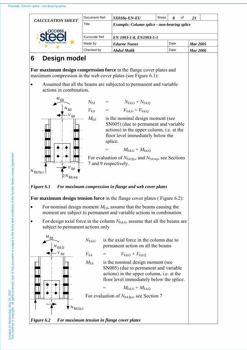
6 Design model For maximum design compression force in the flange cover plates and maximum compression in the web cover plates (see Figure 6.1):
• Assumed that all the beams are subjected to permanent and variable actions in combination.
Ed
Ed
Ed
N
V
M
Ed,fp,cEdN
V
Ed,wpN2
NEd = NEd,G + NEd,Q
VEd = VEd,G + VEd,Q
MEd is the nominal design moment (see SN005) (due to permanent and variable actions) in the upper column, i.e. at the floor level immediately below the splice.
= MEd,G + MEd,Q
For evaluation of NEd,fp,c and NEd,wp, see Sections 7 and 9 respectively.
Figure 6.1 For maximum compression in flange and web cover plates
For maximum design tension force in the flange cover plates ( Figure 6.2):
• For nominal design moment MEd, assume that the beams causing the moment are subject to permanent and variable actions in combination
• For design axial force in the column NEd,G, assume that all the beams are subject to permanent actions only
Ed
Ed
N
V
M
N Ed,fp,t
Ed,G
NEd,G is the axial force in the column due to permanent action on all the beams
VEd = VEd,G + VEd,Q
MEd is the nominal design moment (see SN005) (due to permanent and variable actions) in the upper column, i.e. at the floor level immediately below the splice.
= MEd,G + MEd,Q
For evaluation of NEd,fp,t, see Section 7
Figure 6.2 For maximum tension in flange cover plates
Example: Column splice - non-bearing spliceC
reat
ed o
n W
edne
sday
, May
23,
200
7T
his
mat
eria
l is
copy
right
- a
ll rig
hts
rese
rved
. Use
of t
his
docu
men
t is
subj
ect t
o th
e te
rms
and
cond
ition
s of
the
Acc
ess
Ste
el L
icen
ce A
gree
men
t

SX018a-EN-EU Sheet 9 of 21 Document Ref:
Title
Example: Column splice - non-bearing splice CALCULATION SHEET
Eurocode Ref EN 1993-1-8, EN1993-1-1Made by Edurne Nunez Date Mar 2005
Checked by Abdul Malik Date Mar 2006
7 Flange cover plate NEd,fp,c ≤ NRd,fp,c (1) (For compression in flange cover plate)
NEd,fp,t ≤ NRd,fp,t (2) (For tension in flange cover plate)
Design axial forces
The maximum compressive design force on the flange cover plate (NEd,fp,c) may be calculated from:
( ) ⎟⎟⎠
⎞⎜⎜⎝
⎛++=
uc
ucf,QEd,GEd,
uc
Edcfp,Ed, A
ANN
hMN
∴ ( ) kN 71980,86
32,5042982510260
153cfp,Ed, =⎟
⎠
⎞⎜⎝
⎛×++×
= −N
The maximum tensile design force on the flange cover plate (NEd,fp,t) may be calculated from:
⎟⎟⎠
⎞⎜⎜⎝
⎛−=
uc
ucf,GEd,
uc
Edtfp,Ed, A
AN
hMN
∴ kN 25180,86
32,5082510260
153tfp,Ed, −=⎟
⎠
⎞⎜⎝
⎛×−×
= −N
Note: Since NEd,fp,t is less than zero, there is no tensile force on the flange cover plate and check (2) for tension in the flange cover plate is not required.
SN023
Design resistance The design resistance of the flange cover plate in compression (NRd,fp,c) may be calculated from:
M0
py,fpcfp,Rd, γ
fAN = if p1,fp,j /tfp ≤ 9ε (see note 2 in Table 3.3 of EN1993-1-8)
M1
py,fpfpRd,b,cfp,Rd, γ
fANN
χ== if p1,fp,j /tfp > 9ε
2fpfpfp mm 312012260 =×=×= tbA
p1,fp,j /tfp = 110/12 = 9.2 which is greater than 9ε
EN1993-1-1 §6.2.4(2)
EN1993-1-1 §6.3.1.1(3)
Example: Column splice - non-bearing spliceC
reat
ed o
n W
edne
sday
, May
23,
200
7T
his
mat
eria
l is
copy
right
- a
ll rig
hts
rese
rved
. Use
of t
his
docu
men
t is
subj
ect t
o th
e te
rms
and
cond
ition
s of
the
Acc
ess
Ste
el L
icen
ce A
gree
men
t
SX018a-EN-EU Sheet 10 of 21 Document Ref:
Title
Example: Column splice - non-bearing splice CALCULATION SHEET
Eurocode Ref EN 1993-1-8, EN1993-1-1Made by Edurne Nunez Date Mar 2005
Checked by Abdul Malik Date Mar 2006
For Lcr = 0,6 p1,fp,j and using buckling curve c, χ = 1,0
∴ kN 1108100,1
35531200,1 3cfp,Rd, =×
××= −N
EN1993-1-1 §6.3.1.2
Design check
Since NEd,fp,c < NRd,fp,c (719 kN < 1108 kN), the design axial resistance of the flange cover plate is adequate.
8 Flange cover plate bolt group
fpRd,cfp,Ed, VN ≤
Design axial force The design axial force on the flange cover plate is:
kN 719cfp,Ed, =N (see section 7)
SN023
Design resistances The design resistance of the bolt group for Category A bolts (bearing type):
∑= Rdb,fpRd, FV ( )maxRdb,Rdv,if FF ≥
minRdb,fp )(Fn= maxRdb,Rdv,minRdb, )()(if FFF <≤
Rdv,fpFn= ( ) Rdv,minRdb,if FF >
EN1993-1-8 §3.7
The design bearing resistance of a single bolt on the flange cover plate (Fb,Rd) is given by:
M2
fppu,b1Rdb, γ
α tdfkF =
where:
⎟⎟⎠
⎞⎜⎜⎝
⎛= 01;;
pu,
ubdb ,
ff
αα
⎟⎟⎠
⎞⎜⎜⎝
⎛−−= 52;71417182min
0
fp2,
0
fp2,1 ,,
dp
,;,d
e,k
Example: Column splice - non-bearing spliceC
reat
ed o
n W
edne
sday
, May
23,
200
7T
his
mat
eria
l is
copy
right
- a
ll rig
hts
rese
rved
. Use
of t
his
docu
men
t is
subj
ect t
o th
e te
rms
and
cond
ition
s of
the
Acc
ess
Ste
el L
icen
ce A
gree
men
t

SX018a-EN-EU Sheet 11 of 21 Document Ref:
Title
Example: Column splice - non-bearing splice CALCULATION SHEET
Eurocode Ref EN 1993-1-8, EN1993-1-1Made by Edurne Nunez Date Mar 2005
Checked by Abdul Malik Date Mar 2006
where for the end bolts:
64,0263
503 0
fp1,d =
×==
de
α
and for the inner bolts:
78,041
26380
41
3 0
fp1,d =−
×=−=
dp
α
57,1
510800
pu,
ub ==ff
Hence:
( 64,00,1;57,1;64,0minb == )α for end bolts and
( ) 78,00,1;57,1;78,0minb ==α for inner bolts.
22,47,1
26558,27,1
8,2
0
fp2, =−×
=−de
38,67,126
1504,17,14,1
0
fp2, =−×
=−dp
∴ ( ) 5,25,2;38,6;22,4min1 ==k
Hence:
kN 1881025,1
122451064,05,2)( 3minRdb, =×
××××= −F for end bolts, and
kN 2291025,1
122451078,05,2)( 3maxRdb, =×
××××= −F for inner bolts.
The design shear resistance of a single bolt (Fv,Rd) is given by:
M2
subvpRdv, γ
αβ AfF =
where:
mm 25pa =t
mm 83
243
==d
EN1993-1-8 Table 3.4
Example: Column splice - non-bearing spliceC
reat
ed o
n W
edne
sday
, May
23,
200
7T
his
mat
eria
l is
copy
right
- a
ll rig
hts
rese
rved
. Use
of t
his
docu
men
t is
subj
ect t
o th
e te
rms
and
cond
ition
s of
the
Acc
ess
Ste
el L
icen
ce A
gree
men
t
SX018a-EN-EU Sheet 12 of 21 Document Ref:
Title
Example: Column splice - non-bearing splice CALCULATION SHEET
Eurocode Ref EN 1993-1-8, EN1993-1-1Made by Edurne Nunez Date Mar 2005
Checked by Abdul Malik Date Mar 2006
Since tpa > d/3, the reduction factor should be applied.
( ) ( ) 81,0253248
24938
9
pap =
×+××
=+
=td
dβ
25,1M2 =γ for shear resistance
6,0v =α for class 8.8 bolts
EN1993-1-8 §3.6.1(12)
2s mm 353=A
∴ kN 1101025,1
3538006,081,0 3Rdv, =×
×××= −F
Since Fv,Rd < (Fb,Rd)min i.e 110 kN < 188 kN
1108Rdv,fpfpRd, ×== FnV
∴ kN 880fpRd, =V
Design check Since NEd,fp,c < VRd,fp (719 kN < 880 kN), the design resistance of the flange cover plate bolt group is adequate.
9 Web cover plate
cwp,Rd,wpEd, NN ≤
Design axial force The compressive design force on one web cover plate (NEd,wp) may be calculated from:
uc
ucw,EdwpEd, 2A
ANN =
∴ kN 22280,862
80,211767wpEd, =
××
=N
SN023
Example: Column splice - non-bearing spliceC
reat
ed o
n W
edne
sday
, May
23,
200
7T
his
mat
eria
l is
copy
right
- a
ll rig
hts
rese
rved
. Use
of t
his
docu
men
t is
subj
ect t
o th
e te
rms
and
cond
ition
s of
the
Acc
ess
Ste
el L
icen
ce A
gree
men
t

SX018a-EN-EU Sheet 13 of 21 Document Ref:
Title
Example: Column splice - non-bearing splice CALCULATION SHEET
Eurocode Ref EN 1993-1-8, EN1993-1-1Made by Edurne Nunez Date Mar 2005
Checked by Abdul Malik Date Mar 2006
Design resistance The design resistance of one web cover plate in compression (NRd,wp,c) may be calculated from:
M0
py,wpcwp,Rd, γ
fAN = if p1,wp,j /twp ≤ 9ε (see note 2 , Table 3.3 of EN1993-1-8)
M1
py,wpwpRd,b,cwp,Rd, γ
fANN
χ== if p1,wp,j /twp > 9ε
2wpwpwp mm 12008150 =×=×= tbA
EN1993-1-1 §6.2.4(2)
EN1993-1-1 §6.3.1.1(3)
p1,wp,j /tfp = 110/8 = 13.8 which is greater than 9ε
For Lcr = 0,6 p1,wp,j and using buckling curve c, χ = 0,9
∴ kN 383100,1
35512009,0 3cwp,Rd, =×
××= −N
EN1993-1-1 §6.3.1.2
Design check Since NEd,wp < NRd,wp,c (222 kN < 383 kN), the design resistance of the web cover plate is adequate.
Web cover plates should also be checked for combined bending, shear and axial force in accordance with § 6.2.10 or § 6.2.1 (5) of EN1993-1-1. However in this case the shear force is small and the interaction is judged to be satisfactory by inspection.
10 Web cover plate bolt group
Normally (unless end, edge distances are small) column web bolt group (see section 11) will be critical, but for completeness the verification for the web cover plate bolt group is shown here:
wpRd,wpEd, VN ≤
Design axial force The design axial force on one web cover plate (NEd,wp) was calculated previously as:
NEd,wp = 222 kN
SN023
Example: Column splice - non-bearing spliceC
reat
ed o
n W
edne
sday
, May
23,
200
7T
his
mat
eria
l is
copy
right
- a
ll rig
hts
rese
rved
. Use
of t
his
docu
men
t is
subj
ect t
o th
e te
rms
and
cond
ition
s of
the
Acc
ess
Ste
el L
icen
ce A
gree
men
t
SX018a-EN-EU Sheet 14 of 21 Document Ref:
Title
Example: Column splice - non-bearing splice CALCULATION SHEET
Eurocode Ref EN 1993-1-8, EN1993-1-1Made by Edurne Nunez Date Mar 2005
Checked by Abdul Malik Date Mar 2006
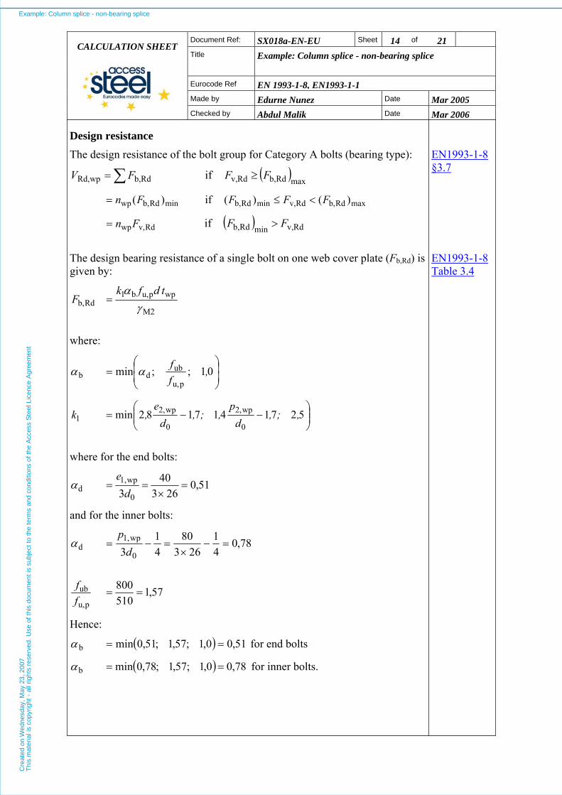
Design resistance The design resistance of the bolt group for Category A bolts (bearing type):
∑= Rdb,wpRd, FV ( )maxRdb,Rdv,if FF ≥
minRdb,wp )(Fn= maxRdb,Rdv,minRdb, )()(if FFF <≤
Rdv,wpFn= ( ) Rdv,minRdb,if FF >
EN1993-1-8 §3.7
The design bearing resistance of a single bolt on one web cover plate (Fb,Rd) is given by:
M2
wppu,b1Rdb, γ
α tdfkF =
EN1993-1-8 Table 3.4
where:
⎟⎟⎠
⎞⎜⎜⎝
⎛= 01;;min
pu,
ubdb ,
ffαα
⎟⎟⎠
⎞⎜⎜⎝
⎛−−= 5271417182min
0
wp2,
0
wp2,1 ,;,
dp
,;,d
e,k
where for the end bolts:
51,0263
403 0
wp1,d =
×==
de
α
and for the inner bolts:
78,041
26380
41
3 0
wp1,d =−
×=−=
dp
α
57,1
510800
pu,
ub ==ff
Hence:
( 51,00,1;57,1;51,0minb == )α for end bolts
( 78,00,1;57,1;78,0minb == )α for inner bolts.
Example: Column splice - non-bearing spliceC
reat
ed o
n W
edne
sday
, May
23,
200
7T
his
mat
eria
l is
copy
right
- a
ll rig
hts
rese
rved
. Use
of t
his
docu
men
t is
subj
ect t
o th
e te
rms
and
cond
ition
s of
the
Acc
ess
Ste
el L
icen
ce A
gree
men
t

SX018a-EN-EU Sheet 15 of 21 Document Ref:
Title
Example: Column splice - non-bearing splice CALCULATION SHEET
Eurocode Ref EN 1993-1-8, EN1993-1-1Made by Edurne Nunez Date Mar 2005
Checked by Abdul Malik Date Mar 2006
07,27,1
26358,27,1
8,2
0
wp2, =−×
=−de
61,27,126
804,17,14,1
0
wp2, =−×
=−dp
∴ ( ) 07,25,2;61,2;07,2min1 ==k
Hence:
kN 831025,1
82451051,007,2)( 3minRdb, =×
××××= −F for end bolts, and
kN 1261025,1
82451078,007,2)( 3maxRdb, =×
××××= −F for inner bolts.
From section 8, the design shear resistance of a single bolt (Fv,Rd), with reduction factor bp =1.0 (i.e. web packing thickness < d/3) would be:
kN 136Rdv, =F
Since Fv,Rd > (Fb,Rd)max i.e 136 kN > 126 kN
∑= Rdb,wpRd, FV
kN 4181262832wpRd, =×+×=V
∴ kN 418wpRd, =V
Design check Since NEd,wp < VRd,wp (222 kN < 418 kN), the design resistance of the web cover plate bolt group is adequate.
Example: Column splice - non-bearing spliceC
reat
ed o
n W
edne
sday
, May
23,
200
7T
his
mat
eria
l is
copy
right
- a
ll rig
hts
rese
rved
. Use
of t
his
docu
men
t is
subj
ect t
o th
e te
rms
and
cond
ition
s of
the
Acc
ess
Ste
el L
icen
ce A
gree
men
t
SX018a-EN-EU Sheet 16 of 21 Document Ref:
Title
Example: Column splice - non-bearing splice CALCULATION SHEET
Eurocode Ref EN 1993-1-8, EN1993-1-1Made by Edurne Nunez Date Mar 2005
Checked by Abdul Malik Date Mar 2006
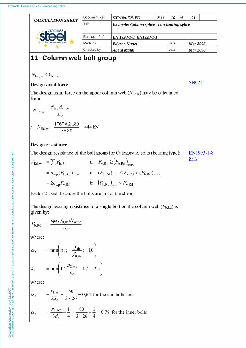
11 Column web bolt group
wRd,wEd, VN ≤
Design axial force
The design axial force on the upper column web (NEd,w) may be calculated from:
uc
ucw,EdwEd,
AAN
N =
∴ kN 44480,86
80,211767wEd, =
×=N
SN023
Design resistance The design resistance of the bolt group for Category A bolts (bearing type):
∑= Rdb,wRd, FV ( )maxRdb,Rdv,if FF ≥
minRdb,wp )(Fn= maxRdb,Rdv,minRdb, )()(if FFF <≤
Rdv,wp2 Fn= ( ) Rdv,minRdb,if FF >
Factor 2 used, because the bolts are in double shear.
EN1993-1-8 §3.7
The design bearing resistance of a single bolt on the column web (Fb,Rd) is given by:
M2
ucw,ucu,b1Rdb, γ
α tdfkF =
where:
⎟⎟⎠
⎞⎜⎜⎝
⎛= 01;;min
ucu,
ubdb ,
ffαα
⎟⎟⎠
⎞⎜⎜⎝
⎛−= 52;7141min
o
wp2,1 ,,
dp
,k
where:
64,0263
503 o
w1,d =
×==
de
α for the end bolts and
78,041
26380
41
3 o
wp1,d =−
×=−=
dp
α for the inner bolts
Example: Column splice - non-bearing spliceC
reat
ed o
n W
edne
sday
, May
23,
200
7T
his
mat
eria
l is
copy
right
- a
ll rig
hts
rese
rved
. Use
of t
his
docu
men
t is
subj
ect t
o th
e te
rms
and
cond
ition
s of
the
Acc
ess
Ste
el L
icen
ce A
gree
men
t
SX018a-EN-EU Sheet 17 of 21 Document Ref:
Title
Example: Column splice - non-bearing splice CALCULATION SHEET
Eurocode Ref EN 1993-1-8, EN1993-1-1Made by Edurne Nunez Date Mar 2005
Checked by Abdul Malik Date Mar 2006
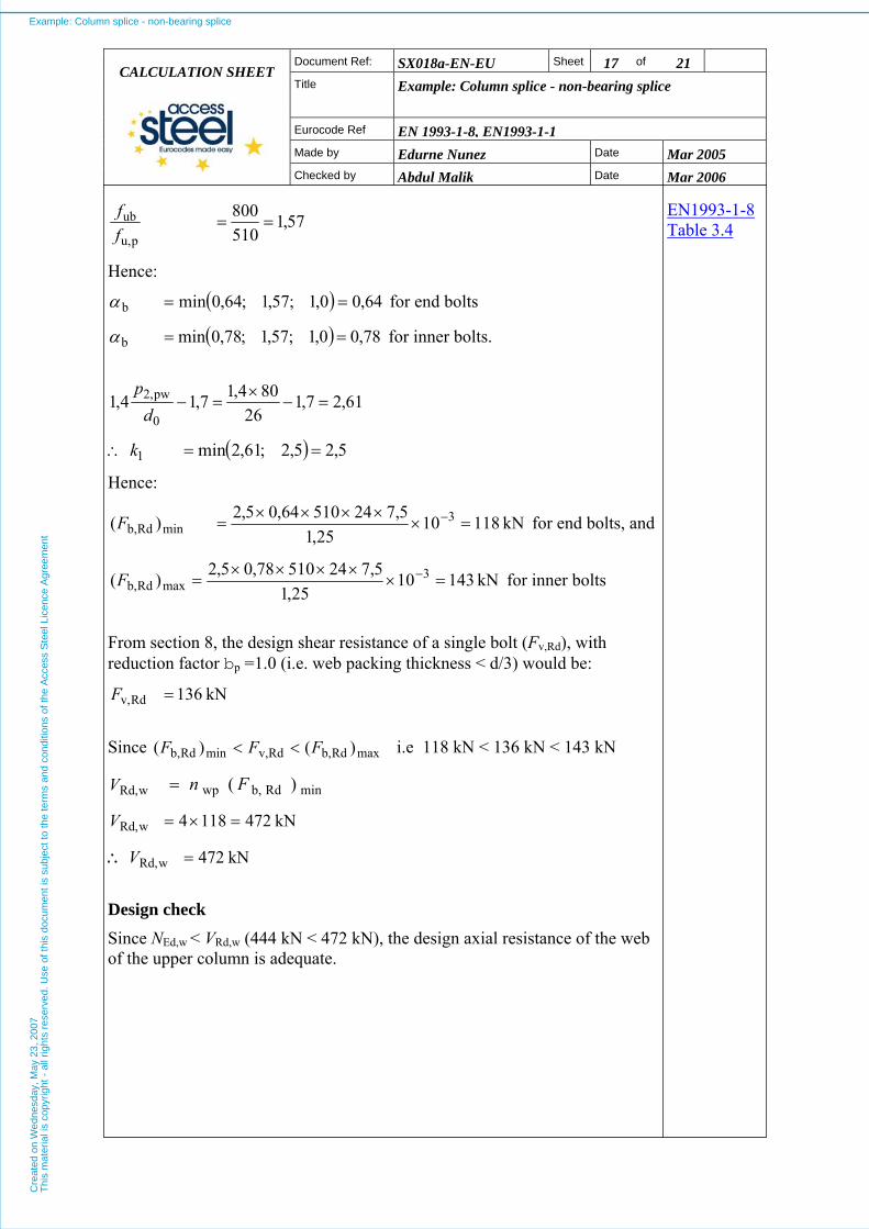
EN1993-1-8 Table 3.457,1
510800
pu,
ub ==ff
Hence:
( 64,00,1;57,1;64,0minb == )α for end bolts
( 78,00,1;57,1;78,0minb == )α for inner bolts.
61,27,1
26804,17,14,1
0
pw2, =−×
=−d
p
∴ ( ) 5,25,2;61,2min1 ==k
Hence:
kN 1181025,1
5,72451064,05,2)( 3minRdb, =×
××××= −F for end bolts, and
kN 1431025,1
5,72451078,05,2)( 3maxRdb, =×
××××= −F for inner bolts
From section 8, the design shear resistance of a single bolt (Fv,Rd), with reduction factor bp =1.0 (i.e. web packing thickness < d/3) would be:
kN 136Rdv, =F
Since i.e 118 kN < 136 kN < 143 kN maxRdb,Rdv,minRdb, )()( FFF <<
wRd,V minRdb,wp )( Fn=
kN 4721184wRd, =×=V
∴ kN 472wRd, =V
Design check Since NEd,w < VRd,w (444 kN < 472 kN), the design axial resistance of the web of the upper column is adequate.
Example: Column splice - non-bearing spliceC
reat
ed o
n W
edne
sday
, May
23,
200
7T
his
mat
eria
l is
copy
right
- a
ll rig
hts
rese
rved
. Use
of t
his
docu
men
t is
subj
ect t
o th
e te
rms
and
cond
ition
s of
the
Acc
ess
Ste
el L
icen
ce A
gree
men
t
SX018a-EN-EU Sheet 18 of 21 Document Ref:
Title
Example: Column splice - non-bearing splice CALCULATION SHEET
Eurocode Ref EN 1993-1-8, EN1993-1-1Made by Edurne Nunez Date Mar 2005
Checked by Abdul Malik Date Mar 2006
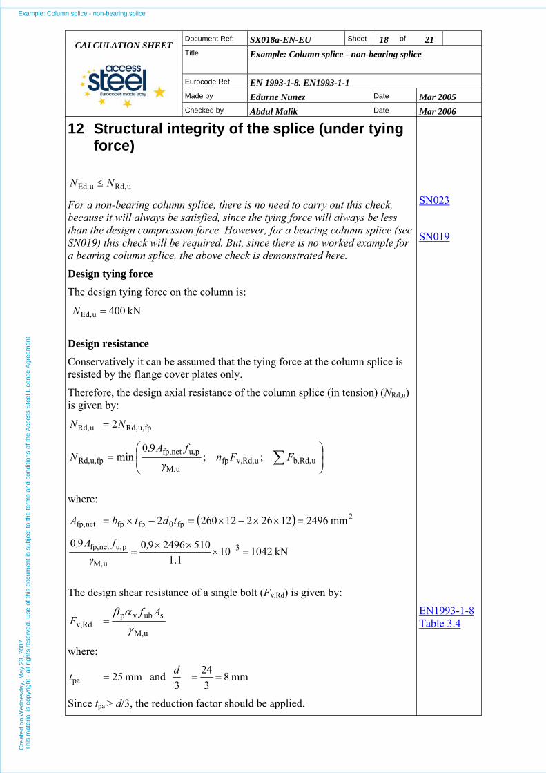
12 Structural integrity of the splice (under tying force)
uRd,uEd, NN ≤
For a non-bearing column splice, there is no need to carry out this check, because it will always be satisfied, since the tying force will always be less than the design compression force. However, for a bearing column splice (see SN019) this check will be required. But, since there is no worked example for a bearing column splice, the above check is demonstrated here.
Design tying force The design tying force on the column is:
kN 400 uEd, =N
SN023
SN019
Design resistance Conservatively it can be assumed that the tying force at the column splice is resisted by the flange cover plates only.
Therefore, the design axial resistance of the column splice (in tension) (NRd,u) is given by:
fpu,Rd,uRd, 2NN =
⎟⎟⎠
⎞⎜⎜⎝
⎛= ∑ uRd,b,uRd,v,fp
uM,
pu,netfp,fpu,Rd, ;;
90min FFn
γfA,
N
where:
( ) 2fp0fpfpnetfp, mm 249612262122602 =××−×=−×= tdtbA
kN 1042101.1
51024969090 3
uM,
pu,netfp, =×××
= −,γ
fA,
The design shear resistance of a single bolt (Fv,Rd) is given by:
uM,
subvpRdv, γ
αβ AfF =
where:
mm 25pa =t and mm 83
243
==d
Since tpa > d/3, the reduction factor should be applied.
EN1993-1-8 Table 3.4
Example: Column splice - non-bearing spliceC
reat
ed o
n W
edne
sday
, May
23,
200
7T
his
mat
eria
l is
copy
right
- a
ll rig
hts
rese
rved
. Use
of t
his
docu
men
t is
subj
ect t
o th
e te
rms
and
cond
ition
s of
the
Acc
ess
Ste
el L
icen
ce A
gree
men
t
SX018a-EN-EU Sheet 19 of 21 Document Ref:
Title
Example: Column splice - non-bearing splice CALCULATION SHEET
Eurocode Ref EN 1993-1-8, EN1993-1-1Made by Edurne Nunez Date Mar 2005
Checked by Abdul Malik Date Mar 2006
( ) ( ) 81,0
253248249
389
pap =
×+××
=+
=td
dβ
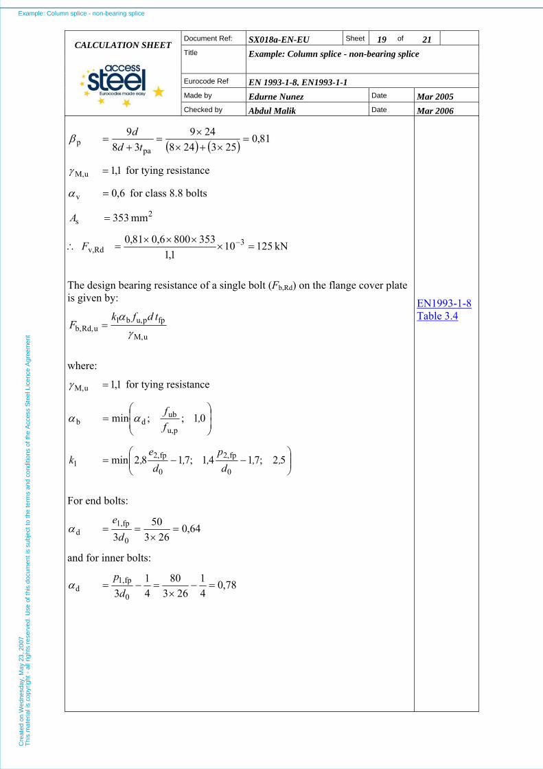
1,1uM, =γ for tying resistance
6,0v =α for class 8.8 bolts
2s mm 353=A
∴ kN 125101,1
3538006,081,0 3Rdv, =×
×××= −F
The design bearing resistance of a single bolt (Fb,Rd) on the flange cover plate is given by:
uM,
fppu,b1uRd,b, γ
α tdfkF =
EN1993-1-8 Table 3.4
where:
1,1uM, =γ for tying resistance
⎟⎟⎠
⎞⎜⎜⎝
⎛= 01;;min
pu,
ubdb ,
ff
αα
⎟⎟⎠
⎞⎜⎜⎝
⎛−−= 52;7141;7182min
0
fp2,
0
fp2,1 ,,
dp
,,d
e,k
For end bolts:
64,0263
503 0
fp1,d =
×==
de
α
and for inner bolts:
78,041
26380
41
3 0
fp1,d =−
×=−=
dp
α
Example: Column splice - non-bearing spliceC
reat
ed o
n W
edne
sday
, May
23,
200
7T
his
mat
eria
l is
copy
right
- a
ll rig
hts
rese
rved
. Use
of t
his
docu
men
t is
subj
ect t
o th
e te
rms
and
cond
ition
s of
the
Acc
ess
Ste
el L
icen
ce A
gree
men
t

SX018a-EN-EU Sheet 20 of 21 Document Ref:
Title
Example: Column splice - non-bearing splice CALCULATION SHEET
Eurocode Ref EN 1993-1-8, EN1993-1-1Made by Edurne Nunez Date Mar 2005
Checked by Abdul Malik Date Mar 2006
57,1
510800
pu,
ub ==ff
Hence:
( 64,00,1;57,1;64,0minb == )α for end bolts, and
( ) 78,00,1;57,1;78,0minb ==α for inner bolts.
22,47,1
26558,27,18,2
0
fp2, =−×
=−d
e
38,67,126
1504,17,14,10
,2 =−×
=−d
p fp
∴ ( ) 5,25,2;38,6;22,4min1 ==k
Hence:
kN 214101,1
122451064,05,2 3uRd,b, =×
××××= −F for end bolts, and
kN 260101,1
122451078,05,2 3uRd,b, =×
××××= −F for inner bolts.
⎟⎟⎠
⎞⎜⎜⎝
⎛= uRd,b,fpuRd,v,fp
uM,
pu,netfp,fpu,Rd, ;;
90min FnFn
γfA,
N
( )26062142;1258;1042minfpu,Rd, ×+××=N
( ) kN 10001988;1000;1042minfpu,Rd, ==N
kN 2000100022 fpu,Rd,uRd, =×== NN
Design check Since NEd,u < NRd,u (400 kN < 2000 kN), the design tying resistance of the column splice is adequate.
Example: Column splice - non-bearing spliceC
reat
ed o
n W
edne
sday
, May
23,
200
7T
his
mat
eria
l is
copy
right
- a
ll rig
hts
rese
rved
. Use
of t
his
docu
men
t is
subj
ect t
o th
e te
rms
and
cond
ition
s of
the
Acc
ess
Ste
el L
icen
ce A
gree
men
t

SX018a-EN-EUDocument Ref: Sheet 21 of 21
Title
Example: Column splice - non-bearing splice CALCULATION SHEET
Eurocode Ref EN 1993-1-8, EN1993-1-1Made by Edurne Nunez Date Mar 2005
Checked by Abdul Malik Date Mar 2006
13 SUMMARY The following table summarizes the values for all the applicable modes of failure. The critical values for normal design and tying are shown in bold type.
Mode of failure Design resistance Design force Ratio:
ResistanceForce
7. Flange cover plate compression
NRd,fp,c = 1108 kN NEd,fp,c = 719 kN 0,65
7. Flange cover plate tension
N/A NEd,fp,t= − 251 kN N/A
8. Flange cover plate bolt group
VRd,fp = 880 kN NEd,fp = 719 kN 0,82
9. Web cover plate NRd,wp,c = 383 kN NEd,wp = 222 kN 0,58
10. Web cover plate bolt group
VRd,wp = 418 kN NEd,wp = 222 kN 0,53
11. Column web bolt group
VRd,w = 472 kN NEd,w = 444 kN 0,94
12. Structural integrity of the splice (under tying force)
NRd,u = 2000 kN NEd,u = 400 kN 0,20
Example: Column splice - non-bearing spliceC
reat
ed o
n W
edne
sday
, May
23,
200
7T
his
mat
eria
l is
copy
right
- a
ll rig
hts
rese
rved
. Use
of t
his
docu
men
t is
subj
ect t
o th
e te
rms
and
cond
ition
s of
the
Acc
ess
Ste
el L
icen
ce A
gree
men
t

Example: Column splice - non-bearing splice SX018a-EN-EU
Quality Record
RESOURCE TITLE Example: Column splice - non-bearing splice
Reference(s)
ORIGINAL DOCUMENT
Name Company Date
Created by Edurne Nunez, SCI 03/2005
Technical content checked by Abdul Malik, SCI 03/2006
Editorial content checked by
Technical content endorsed by the following STEEL Partners:
1. UK G W Owens SCI 17/3/06
2. France A Bureau CTICM 17/3/06
3. Germany A Olsson SBI 17/3/06
4. Sweden C Müller RWTH 17/3/06
5. Spain J Chica Labein 17/3/06
Resource approved by Technical Coordinator
G W Owens SCI 18/07/06
TRANSLATED DOCUMENT
This Translation made by:
Translated resource approved by:
Example: Column splice - non-bearing spliceC
reat
ed o
n W
edne
sday
, May
23,
200
7T
his
mat
eria
l is
copy
right
- a
ll rig
hts
rese
rved
. Use
of t
his
docu
men
t is
subj
ect t
o th
e te
rms
and
cond
ition
s of
the
Acc
ess
Ste
el L
icen
ce A
gree
men
t