Embed Size (px)
Citation preview
AS-InterfaceINSTALLATION GUIDE, TIPS AND TRICKS
2
AS-Interface Installation guide
Tips and Tricks
© www.as-interface.net 3
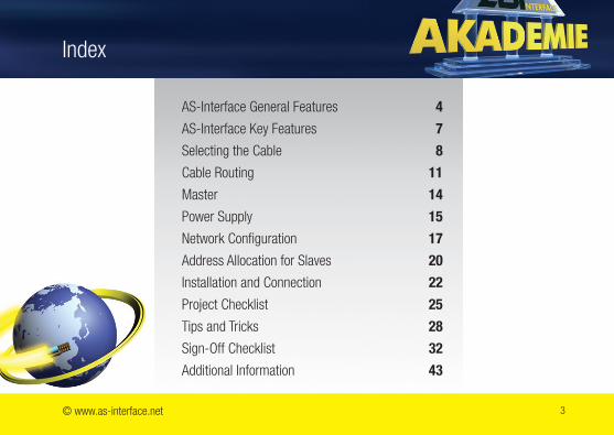
Index
AS-Interface General Features 4
AS-Interface Key Features 7
Selecting the Cable 8
Cable Routing 11
Master 14
Power Supply 15
Network Configuration 17
Address Allocation for Slaves 20
Installation and Connection 22
Project Checklist 25
Tips and Tricks 28
Sign-Off Checklist 32
Additional Information 43
4
AS-Interface,the Worldwide Standard
Europe EN 50295 (since 2008 EN 62026-2)
Worldwide IEC 62026-2
AS-Interface General Features
© www.as-interface.net 5
AS-Interface General Features
R It is important, that only certified products are installed in connection with Bihl+Wiedemann products.
R Products that pass the strict evaluation of an authorized agency are identified by the AS-Interface certification symbol (shadow logo).
6
AS-Interface General Features
R AS-Interface is a potential-free system, symmetrical with respect to ground. Even in industrial environments it offers a high degree of noise immunity without the need for any additional measures such as a shielded cable.
R It is important to not affect the ground symmetry of the system.
R It is possible to use a shielded cable for AS-Interface, but this may have a negative effect on the total network length.
© www.as-interface.net 7
AS-Interface Key Features
R Transmission of data and power on the same cable
R Master / Slave communication process
R Up to 62 slaves on a single AS-Interface network
R Cycle time ≤ 5 ms
R Protection class IP20 to IP69K, depending on housing model
R Standard and safety communications on the same AS-Interface cable
R Maximum network length of 100 m without any topology restrictions ■ Up to 200 m using bus termination ■ Up to 1000 m using repeaters
7
8
We recommend the use of the yellow flat cable
R Two-conductor mechanically coded flat cable ■ Not twisted ■ Not shielded ■ Not terminated
R Data and power over one cable ■ 240 W maximum output power (30 VDC, 8 A)
R Different cable jacket materials are available
R Different colors for different applications
Selecting the Cable
■ PUR ■ TPE
■ EPDM ■ Rubber
■ Yellow: AS-Interface ■ Black: Auxiliary power 24 V (AUX)
© www.as-interface.net 9
Selecting the Cable
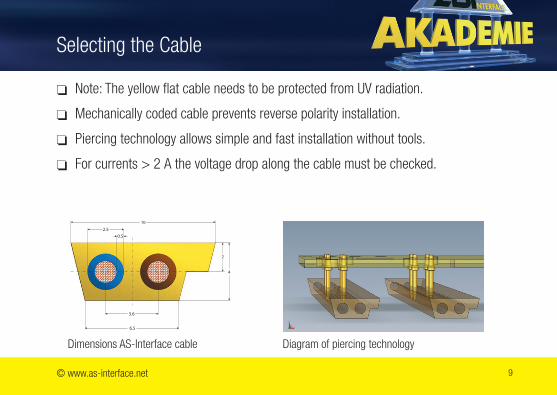
R Note: The yellow flat cable needs to be protected from UV radiation.
R Mechanically coded cable prevents reverse polarity installation.
R Piercing technology allows simple and fast installation without tools.
R For currents > 2 A the voltage drop along the cable must be checked.
Dimensions AS-Interface cable Diagram of piercing technology
2.5
0.5
3.6
6.5
10
Selecting the Cable
If the standard AS-Interface cable cannot be used:
R Almost any standard round cable can be used.
R Two-conductor cable with a conductor diameter between 0.75 mm2 and 2.5 mm2
R In this case, the power requirements and the voltage drop must be checked!
R The attainable network length might be reduced if cables are used that do not conform to the specification.
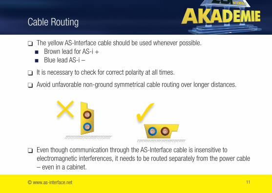
R The yellow AS-Interface cable should be used whenever possible. ■ Brown lead for AS-i + ■ Blue lead AS-i –
R It is necessary to check for correct polarity at all times.
R Avoid unfavorable non-ground symmetrical cable routing over longer distances.
R Even though communication through the AS-Interface cable is insensitive to electromagnetic interferences, it needs to be routed separately from the power cable – even in a cabinet.
© www.as-interface.net 11
Cable Routing
× 3
12
Cable Routing
AS-i −
AS-i −
AS-i −
AS-i +
AS-i +
AS-i +
AS-i −
AS-i +
AS-i −
AS-i +
AS-i −
AS-i +
Falscher Anschluss der Klemmen. AS-i + und AS-i - haben nicht immer den selben Abstand zueinander und es entsteht eine Fläche wo EMV Störungen Probleme verursachen können.
Richtiger Anschluss der Klemmen. AS-i + und AS-i - haben immer den selben Abstand zueinander, was sehr wichtig gegen EMV Störungen ist.
AS-i −
AS-i −
AS-i −
AS-i +
AS-i +
AS-i +
AS-i −
AS-i +
AS-i −
AS-i +
AS-i −
AS-i +
Falscher Anschluss der Klemmen. AS-i + und AS-i - haben nicht immer den selben Abstand zueinander und es entsteht eine Fläche wo EMV Störungen Probleme verursachen können.
Richtiger Anschluss der Klemmen. AS-i + und AS-i - haben immer den selben Abstand zueinander, was sehr wichtig gegen EMV Störungen ist.
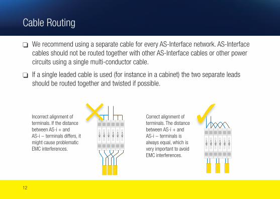
Incorrect alignment of terminals. If the distance between AS-i + and AS-i − terminals differs, it might cause problematic EMC interferences.
Correct alignment of terminals. The distance between AS-i + and AS-i − terminals is always equal, which is very important to avoid EMC interferences.
× 3
R We recommend using a separate cable for every AS-Interface network. AS-Interface cables should not be routed together with other AS-Interface cables or other power circuits using a single multi-conductor cable.
R If a single leaded cable is used (for instance in a cabinet) the two separate leads should be routed together and twisted if possible.
© www.as-interface.net 13
Cable Installation, EMC considerations
R EMC protection through protection diodes, varistors, or RC filters must be used for all switched inductive loads, such as master control relays and relay coils, valves, breakers etc., if this is not already integrated in the products. Please check the manufacturer’s instructions.
R If frequency inverters are installed, the use of network filters, output filters and shielded motor cables are recommended. ■ Observe installation guidelines in the manufacturer’s instructions. ■ Cable shields between filters, frequency inverters, and motors need to be
connected directly to the system ground at both ends, using a sufficient cross section (min. 4 mm2).
R Keep the distance to potential sources of interferences (for example frequency inverters and their cables) as large as possible.
14
R This recommendation is based on Specification 3.0
R All AS-Interface Masters are backward compatible.
R If masters that are designed according to a specification prior to 3.0 are installed, the use of some functions could be limited (for instance diagnostics).
R AS-Interface slaves with the profiles S-7.5.5, S-7.A.5, S-B.A.5, S-7.A.7, S-7.A.A, S-7.A.8, S-7.A.9 and S-6.0 require a master with profile M4 (first defined in AS-interface Specification 3.0).
R All AS-Interface Masters 3.0 comply with profile M4.
Master
© www.as-interface.net 15
Power Supply
R Use only AS-Interface power supplies (PELV). ■ PELV = Protective Extra Low Voltage
R The PE-connector on the AS-Interface power supply (protective earth) must be grounded (if available).
R The ground on the AS-i-network (GND, Ground, Shield) must be connected to the system ground.
R Both AS-i − and AS-i + must not be grounded.
R Output voltage AS-i: 29.5 to 31.6 V DC
R AS-Interface power supplies deliver up to 8 A (model specific).
16
Power Supply
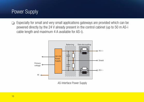
R Especially for small and very small applications gateways are provided which can be powered directly by the 24 V already present in the control cabinet (up to 50 m AS-i cable length and maximum 4 A available for AS-i ).
Primary voltage
Balancing Data decoupling
Shield
AS-i +
AS-i −
30 V DC PowerSupply
PE
AS-Interface Power Supply
© www.as-interface.net 17
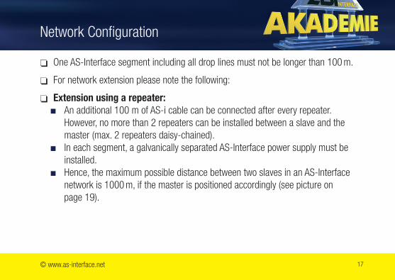
R One AS-Interface segment including all drop lines must not be longer than 100 m.
R For network extension please note the following:
R Extension using a repeater: ■ An additional 100 m of AS-i cable can be connected after every repeater.
However, no more than 2 repeaters can be installed between a slave and the master (max. 2 repeaters daisy-chained).
■ In each segment, a galvanically separated AS-Interface power supply must be installed.
■ Hence, the maximum possible distance between two slaves in an AS-Interface network is 1000 m, if the master is positioned accordingly (see picture on page 19).
Network Configuration
18
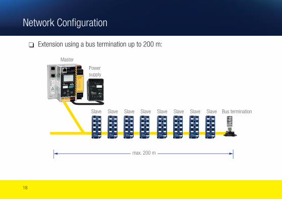
R Extension using a bus termination up to 200 m:
max. 200 m
Master
Slave Slave Slave Slave Slave Slave Slave Bus terminationSlave
Network Configuration
Power supply
© www.as-interface.net 19
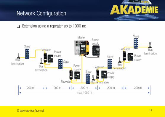
R Extension using a repeater up to 1000 m:
Slave
Slave
Slave
SlaveMaster
Repeater Repeater
Repeater
Repeater
Slave
200 m 200 m 200 m 200 m 200 m
max. 1000 m
Network Configuration
Bus termination
Bus termination
Power supply
Power supply
Power supply
Power supply
Power supply
Bus termination
Bus termination
Bus termination
20
Address Allocation for Slaves
R For AS-Interface 31 slave addresses are available.
R There is a difference between standard address allocation and extended address allocation. The address allocation mode of a slave is set by the manufacturer.
R For standard address allocations, each slave utilizes a full address (1 ... 31).
R For extended address allocation each address can be used by 2 slaves (1A ... 31A, 1B ... 31B).
R Example: Address 3 can be used by: ■ One standard slave with address 3 or ■ One extended slave with address 3A or ■ One extended slave with address 3B or ■ Two extended slaves with addresses 3A and 3B
R Combining a standard and an extended slave in the same address is not possible e.g. 3 and 3A or 3B.
×
3
© www.as-interface.net 21
Address Allocation for Slaves
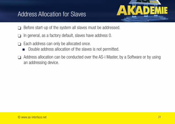
R Before start-up of the system all slaves must be addressed.
R In general, as a factory default, slaves have address 0.
R Each address can only be allocated once. ■ Double address allocation of the slaves is not permitted.
R Address allocation can be conducted over the AS-i Master, by a Software or by using an addressing device.
22
Installation and Connection
R Connecting modules to AS-Interface networks ■ Numerous different module concepts are available from the various
manufacturers. ■ It is necessary to follow the manufacturer’s installation guidelines.
© www.as-interface.net 23
Installation and Connection, I/O Supply
R Whenever possible, sensors and actuators should be supplied directly by the inputs or outputs slave respectively.
R This cable should be kept separate from the power cable and as short as possible. ■ Slave modules should be installed as close as possible to sensors and actuators.
R Ground-free sensors/actuators: Grounding of peripheral devices, galvanically connected with AS-i potential, is not permitted according to specification. It must be avoided to maintain a high degree of interference immunity.
R If the sensor/actuator has a ground connection that is galvanically isolated from the AS-Interface network, it must be connected to the system ground.
24
M12 Connection
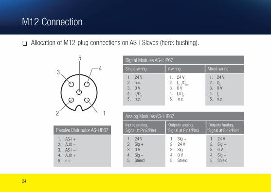
R Allocation of M12-plug connections on AS-i Slaves (here: bushing).
Analog Modules AS-i: IP67
Inputs analog, Signal at Pin2/Pin4
Outputs analog, Signal at Pin1/Pin3
Outputs Analog, Signal at Pin2/Pin4
1. 24 V2. Sig +3. 0 V4. Sig −5. Shield
1. Sig +2. 24 V3. Sig −4. 0 V5. Shield
1. 24 V2. Sig +3. 0 V4. Sig −5. Shield
Digital Modules AS-i: IP67
Single-wiring Y-wiring Mixed-wiring
1. 24 V2. n.c.3. 0 V4. I
n/O
n
5. n.c.
1. 24 V2. I
n+1/O
n+1
3. 0 V4. I
n/O
n
5. n.c.
1. 24 V2. O
n
3. 0 V4. I
n
5. n.c.
12
34
5
Passive Distributor AS-i IP67
1. AS-i +2. AUX −3. AS-i −4. AUX +5. n.c.
© www.as-interface.net 25
Project Checklist
How many inputs and outputs are needed? ■ The number of inputs and outputs determines the number of AS-Interface
networks.
How much power is required for the peripheral devices? ■ The total power demand of the required modules determines the size of the
AS-Interface power supply. Since power supplies cannot be wired in parallel, the size of the installed power supply must be chosen according to the power consumption. If the AS-Interface network is segmented using repeaters, the power for each segment is supplied separately and the entire network can consume considerably more power.
Are special cables needed? ■ In general, a combination of flat and round cables is possible. Environmental
influences must be considered when choosing a suitable cable material.
26
Is the address allocation correct? ■ To maintain installation clarity it is suggested to maintain a list that clearly
identifies each slave with its assigned address. ■ In some cases, the master may not recognize double address allocations as error.
Which modules use which addresses? ■ It is imperative to carefully mark those modules or slaves that already received an
address.
When are modules installed? ■ After the above rules have been observed. The cable can be installed at any time.
Project Checklist
© www.as-interface.net 27
How to configure the system? ■ The configuration is simply read by registering the AS-Interface profile of each
slave into the master. In general, this process occurs automatically, but can also be performed manually using the PLC software.
How will the slaves be recognized? ■ First, it is necessary to check if the master recognized all slaves. Subsequently,
it can be switched into protected mode and then the PLC program can be set to RUN.
How can the system be tested? ■ Input/output tests are performed as usual in the PLC. This means, the sensors
are locally activated and verified in the PLC.
Project Checklist
28
Tips and Tricks
How can the system be activated? ■ Optionally, the operating software can be programmed as usual or an existing
software can be used. If an existing software is to be used, it may be necessary to adjust the symbolic assignment of the addresses.
How to check if ground faults exist on the AS-Interface network? ■ By using a ground fault detection device, available as a separate component as
well as integrated in the master and/or power supply. ■ In general, it is suggested to install a ground fault detection as part of the AS-i
networks. Most of Bihl+Wiedemann devices contain an earth fault monitor.
© www.as-interface.net 29
Tips and Tricks
What else can be done to achieve a higher noise immunity? ■ The connection “Shield” on the AS-i power supply must be connected directly
and with good HF characteristics to the machine ground of the system. This does not present grounding for safety reasons but a functional ground to operate the AS-i cable symmetrically against the ground. If a shielded cable is used, the cable shield must be connected to this point (and only here).
■ Good symmetry should also be maintained towards other electrical noise sources (drives, welding equipment, etc.). The cables connecting active I/O modules and sensors or actuators, respectively, should be limited to a maximum of 2 m.
■ Whenever there is a possibility of high electrostatic charge (for instance polishing machines, die cast machines, or when wrapping/unwrapping plastic foils) it may be necessary to apply additional protective measures, for instance discharge brushes.
30
Can the AS-i cable be routed parallel to power cables? ■ Even if the communication via the AS-Interface is insensitive to noise, it should
still be routed separately from power cables – even in a cabinet. ■ Maximum possible distances to potential interference sources (such as frequency
inverters) should be maintained. ■ Each AS-Interface network should have its own cable, for example AS-Interface
cables should not be routed with other cables using a multi-conductor cable. ■ If single conductors are needed (for instance in cabinets), conductor pairs must
be routed in parallel. Standard single-lead cables must be routed together or twisted.
Tips and Tricks
© www.as-interface.net 31
Tips and Tricks
Considerations when using an 8 A-AS-i power supply
If more than the typically normal 2 A are transferred through the AS-i network, the following limitations need to be considered when designing the network:
■ The voltage drop along the AS-i network increases. Guideline: If 2 A are transferred using 100 m cable with a diameter of 1.5 mm2, the resulting voltage drop is about 5 V.
■ The piercing contacts are designed for certain maximum constant amperage rating, below 8 A. It is very important to refer to the manufacturer’s data sheets.
Considerations when using a standard 24 V power supply ■ The applied AS-i Slaves have to be able to work with 24 V as well. ■ It is recommended that the voltage at the end of the AS-i cable is still at least
20 V.
32
Sign-Off Checklist
R The installation was done according to the installation guidelines of the different manufacturers.
R The segment length is equal to or shorter than 100 m. Segment length is the sum of all “drop lines” in a segment.
R The connection to the slave farthest from the master runs through no more than two repeaters.
R If network extension is accomplished using manufacturer specific products, the manufacturer’s data sheets and information must be observed.
R A distance of at least 10 to 20 cm has been maintained between AS-i networks or sensor networks and medium interference sources such as controls with inductive loads or low power emission supplies.
R The Ground/PE/Shield connection of the AS-i power supplies is connected to the system ground to maintain symmetry.
© www.as-interface.net 33
R A distance larger than 50 cm has been maintained between AS-i networks or sensor networks and strong interferences sources such as: welding robots, switched power supplies and frequency inverters.
R Wherever possible use the yellow profile AS-Interface cable, otherwise use a twisted two-conductor 2×1.5 mm2 cable.
R The current carrying capacity of connection T’s or terminal connectors has been checked (see manufacturer’s data sheet).
R How to apply the bus configuration to the AS-i master? ■ In the master by pushing a key ■ In the control system through the hardware configuration ■ In the control system through a user application
Sign-Off Checklist
34
Sign-Off Checklist
R How are slaves connected to the network documented (type, address, and identification data)? ■ Drawing of the electrical layout ■ Manually inserted in a table ■ Printed table based on the hardware configuration ■ Printed table with data read by the AS-i master
R How is the network topology documented?
The documentation must show the topology such as: line, tree, star, drop lines, etc., and the segmentation with the actually used cable length of AS-i network. AS-i power supplies, slaves with their corresponding address, and repeaters, if used, should be included.
■ Drawing of the electrical layout ■ Graphically ■ Not at all
© www.as-interface.net 35
R Is the maximum power consumption of the AS-i network smaller than the maximum current supplied by the AS-i power supply?
R If used, the 24 V auxiliary power must be checked similarly.
R Theoretical maximum current load: the current requirement can be calculated by referring to the data sheets of the used components.
R The value of the AS-i voltage at the end of each segment (the point farthest away from the AS-i power supply) should be determined under full load. The measurement point (M) must be shown in the network topology. This value must be determined for all segments. ■ The AS-i voltage between AS-i + and AS-i − must be between U± = 26.5 and
31.6 V.
Sign-Off Checklist
36
Sign-Off Checklist
R The current load on the AS-i power supply, measured with a clamp meter under full load conditions, must be compared to the maximum permissible current load of the power supply. This value must be determined for all segments. It is recommended that this maximum load does not exceed 90% of the power supply capacity.
R Using analyzer devices or diagnostic functions in the master, the number of faulty telegrams during operation can be determined. At least 100,000 telegrams need to be evaluated (about 9 minutes for 31 slaves). ■ The three slaves with the largest number of errors should be recorded during
system sign-off. ■ According to the AS-Interface specification, the admissible error rate must be
below 0.1%. Error rate = (faulty telegrams*100)/number of telegrams
R The diagnostic results must be documented (for instance by reading and interpreting the flags in the AS-i masters).
© www.bihl-wiedemann.com 37
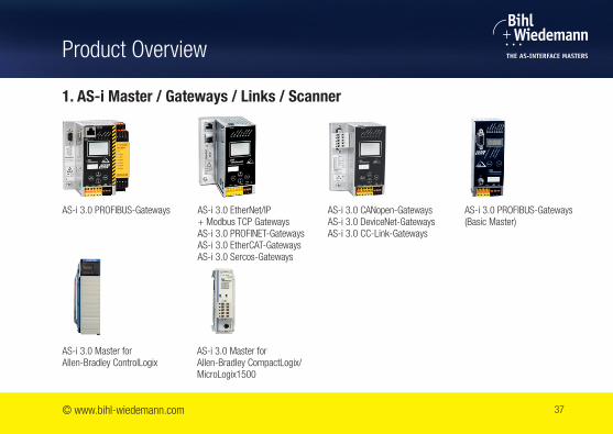
Product Overview
1. AS-i Master / Gateways / Links / Scanner
AS-i 3.0 PROFIBUS-Gateways AS-i 3.0 CANopen-GatewaysAS-i 3.0 DeviceNet-Gateways AS-i 3.0 CC-Link-Gateways
AS-i 3.0 Master forAllen-Bradley ControlLogix
AS-i 3.0 EtherNet/IP + Modbus TCP GatewaysAS-i 3.0 PROFINET-GatewaysAS-i 3.0 EtherCAT-Gateways AS-i 3.0 Sercos-Gateways
AS-i 3.0 PROFIBUS-Gateways(Basic Master)
AS-i 3.0 Master forAllen-Bradley CompactLogix/ MicroLogix1500
38
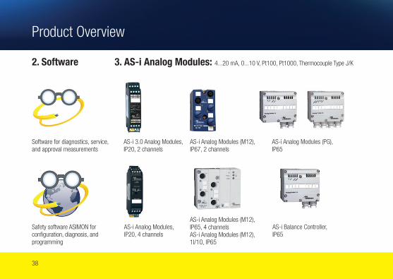
2. Software
Software for diagnostics, service, and approval measurements
AS-i Analog Modules (M12), IP67, 2 channels
AS-i 3.0 Analog Modules,IP20, 2 channels
AS-i Analog Modules (PG), IP65
Safety software ASIMON for configuration, diagnosis, and programming
AS-i Analog Modules (M12),IP65, 4 channelsAS-i Analog Modules (M12), 1I/1O, IP65
AS-i Analog Modules,IP20, 4 channels
AS-i Balance Controller, IP65
3. AS-i Analog Modules: 4...20 mA, 0...10 V, Pt100, Pt1000, Thermocouple Type J/K
Product Overview
© www.bihl-wiedemann.com 39
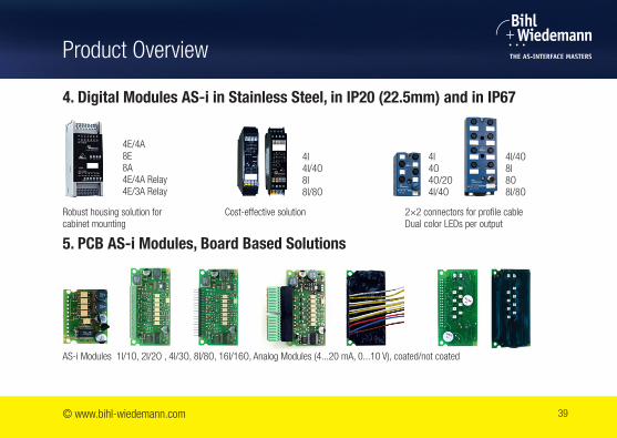
4. Digital Modules AS-i in Stainless Steel, in IP20 (22.5mm) and in IP67
5. PCB AS-i Modules, Board Based Solutions
Robust housing solution for cabinet mounting
Cost-effective solution 2×2 connectors for profile cableDual color LEDs per output
4E/4A8E8A4E/4A Relay4E/3A Relay
4I4I/4O8I8I/8O
4I/4O8I8O8I/8O
4I4O4O/2O4I/4O
AS-i Modules 1I/1O, 2I/2O , 4I/3O, 8I/8O, 16I/16O, Analog Modules (4...20 mA, 0...10 V), coated/not coated
Product Overview
40
Product Overview
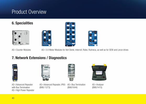
6. Specialities
7. Network Extensions / Diagnostics
AS-i Counter Modules AS-i 3.0 Motor Modules for Itoh Denki, Interroll, Rolex, Rulmeca, as well as for SEW and Lenze drives
AS-i Advanced Repeaterwith Bus TerminationAS-i High Power Repeater
AS-i Analyser (BWU1415)
AS-i Bus Termination (BWU1644)
AS-i Advanced Repeater, IP65 (BWU 1273)

© www.bihl-wiedemann.com 41
8. Power Supplies
AS-i Power Supply, 1.8 A
AS-i Power Supply, 4 A/8 A
AS-i Wide Range Power Supply, 8 A
Power Supply for AS-i Master, 4 A/8 A
AS-i Power Extender AS-i Power Supply, with 3 phases, 8 A
AS-i Module forPower Decoupling
Product Overview

42
9. Safety: for large, medium-size and small systems (up to SIL3/Cat4/PLe)
AS-i 3.0 PROFIBUS-Gateways withintegrated SafetyMonitor
AS-i 3.0 Gateways PROFIsafevia PROFIBUS or PROFINET
AS-i Safety Output Modules AS-i Safety Input/Output Modules, IP20
AS-i Safety Input Modules (M12), IP67
Signaling Devices
AS-i 3.0 EtherNet/IP + Modbus-Gateways*AS-i 3.0 PROFINET- Gateways*AS-i 3.0 EtherCAT- Gateways*AS-i 3.0 Sercos-Gateways**with integrated Safety Monitor
AS-i 3.0 CANopen- Gateways with integrated Safety Monitor
Safety Basic Monitor: Ideal solution forsmall systems
CIP Safety Gateways over EtherNet/IP and Sercos
Product Overview
© www.bihl-wiedemann.com 43
Data sheets and manufacturer’s guidelines
AS-i Academy: www.as-interface.net/media/ academy/content/sys/start/start.en.html
www.bihl-wiedemann.com
Information about further products can be found at www.bihl-wiedemann.com
Notes:These recommendations were made according to specification 3.0None of the contributors can be held responsible for the appearance of any inaccurate information or recommendations. Safety technology is not part of these installation recommendations. Data sheets and manufacturer’s information must be strictly observed!
Additional Information

No longer miss a bus with our Safety Gateways
Bihl+Wiedemann GmbH · Flosswoerthstrasse 41 · 68199 Mannheim, Germany Tel.: +49 (0) 621 33 99 60 · Fax: +49 (0) 621 33 92 239 · [email protected] · www.bihl-wiedemann.com


![[Clarinet institute] wiedemann staccato](https://img.pdfslide.net/doc/110x75/558fd3ba1a28ab1c5e8b461d/clarinet-institute-wiedemann-staccato.jpg)
![[Clarinet_Institute] Wiedemann Staccato.pdf](https://img.pdfslide.net/doc/110x75/5695d0061a28ab9b02909c61/clarinetinstitute-wiedemann-staccatopdf.jpg)