Embed Size (px)
Citation preview

Preface, Contents
AS-Interface (AS-i)1
The AS-i Master 2
Further AS-i System Components3
The Master Mode – Commands, Se-quence, Programming
4
Appendix
References A
Glossary B
SIMATIC NET – Support and Trai-ning C
12/99C79000-G8976-C089Release 03
AS-Interface – Introduction andBasic Information
Manual
SIMATIC NET
Industrial Ethernet
PROFIBUS
AS-Interface
AS-Interface

Safety GuidelinesThis manual contains notices which you should observe to ensure your own personal safety, as well as toprotect the product and connected equipment. These notices are highlighted in the manual by a warningtriangle and are marked as follows according to the level of danger:
!Danger
indicates that death, severe personal injury or substantial property damage will result if proper precautionsare not taken.
!Warning
indicates that death, severe personal injury or substantial property damage can result if proper precau-tions are not taken.
!Caution
indicates that minor personal injury or property damage can result if proper precautions are not taken.
Note
draws your attention to particularly important information on the product, handling the product, or to a particular part of the documentation.
Qualified PersonnelOnly qualified personnel should be allowed to install and work on this equipment. Qualified persons aredefined as persons who are authorized to commission, to ground, and to tag circuits, equipment, and sy-stems in accordance with established safety practices and standards.
Correct UsageNote the following
!Warning
This device and its components may only be used for the applications described in the catalog or thetechnical description, and only in connection with devices or components from other manufacturers whichhave been approved or recommended by Siemens.
This product can only function correctly and safely if it is transported, stored, set up, and installedcorrectly, and operated and maintained as recommended.
TrademarksSIMATIC�, SIMATIC HMI� and SIMATIC NET� are registered trademarks of the SIEMENS AG.
Third parties using for their own purpose any other names in this document which refer to trademarksmight infringe upon the rights of the trademark owners.
We have checked the contents of this manual for agreement with thehardware and software described. Since deviations cannot beprecluded entirely, we cannot guarantee full agreement. However,the data in this manual are reviewed regularly and any necessarycorrections included in subsequent editions. Suggestions forimprovement are welcomed.
Technical data subject to change.� Siemens AG 1999
Disclaimer of LiabilityCopyright � Siemens AG 19989All rights reserved
The reproduction, transmission or use of this document or itscontents is not permitted without express written authority.Offenders will be liable for damages. All rights, including rightscreated by patent grant or registration of a utility model or design, arereserved.
���������
A&DGeschaeftsgebiet Industrie–AutomatisierungPostfach 4848, D-90327 Nuernberg
Siemens Aktiengesellschaft C79000-G8976-C089

iSIMATIC NET AS-Interface – Introduction and Basic InformationC79000-G8976-C089/03
Preface
Purpose of the Manual
This manual contains basic information and an introduction to the AS-Interfacesystem concept and the corresponding system components.
You require this manual to understand the manuals that are shipped with the AS-isystem components, particularly with the AS-i master.
This release of the manual contains supplementary information relating to theexpansion of the AS-i master specification and the extended SIMATIC NETproduct range.
This involves the following aspects:
� The extended addressing mode allows the addressing of up to 62 AS-i slaves.
� Integrated, simple analog value transfer.
The AS-Interface is an open international standard
The AS-Interface is the open international standard EN 50 295. Leadingmanufacturers of actuators and sensors support the AS-Interface world-wide. Theelectrical and mechanical specifications are available for interested companies.
Further Support – Who to Contact
If you have technical questions about using the product described here, pleasecontact your local Siemens representative.
You will find further information in the appendix in “Support and Training”.

Preface
iiSIMATIC NET AS-Interface – Introduction and Basic Information
C79000-G8976-C089/03
Other Documentation
You should also read the product information bulletins supplied with the AS-icomponents from SIMATIC NET and the manuals that can be ordered additionally.
Refer also to the references in the appendix of this manual.
�
iiiSIMATIC NET AS-Interface – Introduction and Basic InformationC79000-G8976-C089/03
Contents
1 AS-Interface (AS-i) 1-1. . . . . . . . . . . . . . . . . . . . . . . . . . . . . . . . . . . . . . . . . . . . . . . . . . . . . .
1.1 Area of Application 1-2. . . . . . . . . . . . . . . . . . . . . . . . . . . . . . . . . . . . . . . . . . . . . .
1.2 Overview of the AS-i System Components 1-4. . . . . . . . . . . . . . . . . . . . . . . . . . 1.2.1 AS-i Masters 1-5. . . . . . . . . . . . . . . . . . . . . . . . . . . . . . . . . . . . . . . . . . . . . . . . . . . . 1.2.2 AS-i Slaves 1-6. . . . . . . . . . . . . . . . . . . . . . . . . . . . . . . . . . . . . . . . . . . . . . . . . . . . . 1.2.3 Further AS-i System Components 1-8. . . . . . . . . . . . . . . . . . . . . . . . . . . . . . . . .
1.3 System Characteristics and Important Data 1-9. . . . . . . . . . . . . . . . . . . . . . . . .
2 The AS-i Masters 2-1. . . . . . . . . . . . . . . . . . . . . . . . . . . . . . . . . . . . . . . . . . . . . . . . . . . . . . .
2.1 AS-i Masters for the SIMATIC S7-200 2-2. . . . . . . . . . . . . . . . . . . . . . . . . . . . . .
2.2 AS-i Masters for the SIMATIC S7-300 2-4. . . . . . . . . . . . . . . . . . . . . . . . . . . . . .
2.3 AS-i Master for SIMATIC S5 PLCs in the Higher Performance Range 2-6. .
2.4 AS-i Master for SIMATIC S5 PLCs in the Lower Performance Range 2-7. . .
2.5 AS-i Gateways 2-8. . . . . . . . . . . . . . . . . . . . . . . . . . . . . . . . . . . . . . . . . . . . . . . . . .
2.6 AS-i Master for ET 200X 2-10. . . . . . . . . . . . . . . . . . . . . . . . . . . . . . . . . . . . . . . . .
2.7 AS-i Master for PC-AT 2-11. . . . . . . . . . . . . . . . . . . . . . . . . . . . . . . . . . . . . . . . . . .
3 Further AS-i System Components 3-1. . . . . . . . . . . . . . . . . . . . . . . . . . . . . . . . . . . . . . .
3.1 The AS-i Cable 3-2. . . . . . . . . . . . . . . . . . . . . . . . . . . . . . . . . . . . . . . . . . . . . . . . .
3.2 AS-i Modules: Blocks of the AS-i Slaves 3-3. . . . . . . . . . . . . . . . . . . . . . . . . . . .
3.3 Installing an AS-i Module 3-5. . . . . . . . . . . . . . . . . . . . . . . . . . . . . . . . . . . . . . . . .
3.4 AS-Interface Repeater / Extender 3-6. . . . . . . . . . . . . . . . . . . . . . . . . . . . . . . . .
3.5 Addressing Unit 3-9. . . . . . . . . . . . . . . . . . . . . . . . . . . . . . . . . . . . . . . . . . . . . . . . .
3.6 SCOPE Diagnostic Software for AS-Interface 3-10. . . . . . . . . . . . . . . . . . . . . . .
4 The Master Mode – Commands, Sequence, Programming 4-1. . . . . . . . . . . . . . . . .
4.1 Master-Slave Principle 4-2. . . . . . . . . . . . . . . . . . . . . . . . . . . . . . . . . . . . . . . . . . . 4.1.1 Tasks and Functions of the AS-i Master 4-3. . . . . . . . . . . . . . . . . . . . . . . . . . . . 4.1.2 How an AS-i Slave Functions 4-4. . . . . . . . . . . . . . . . . . . . . . . . . . . . . . . . . . . . .
4.2 Data Transfer 4-5. . . . . . . . . . . . . . . . . . . . . . . . . . . . . . . . . . . . . . . . . . . . . . . . . . . 4.2.1 The Operating Phases 4-7. . . . . . . . . . . . . . . . . . . . . . . . . . . . . . . . . . . . . . . . . . . 4.2.2 Interface Functions 4-10. . . . . . . . . . . . . . . . . . . . . . . . . . . . . . . . . . . . . . . . . . . . . . 4.2.3 Operating Extended AS-i Slaves with Standard AS-i Masters 4-11. . . . . . . . . .
Contents
ivSIMATIC NET AS-Interface – Introduction and Basic Information
C79000-G8976-C089/03
A References A-1. . . . . . . . . . . . . . . . . . . . . . . . . . . . . . . . . . . . . . . . . . . . . . . . . . . . . . . . . . . . .
B Glossary B-1. . . . . . . . . . . . . . . . . . . . . . . . . . . . . . . . . . . . . . . . . . . . . . . . . . . . . . . . . . . . . . .
C SIMATIC NET – Support and Training C-1. . . . . . . . . . . . . . . . . . . . . . . . . . . . . . . . . . . .
Index
�

1-1SIMATIC NET AS-Interface – Introduction and Basic InformationC79000-G8976-C089/03
AS-Interface (AS-i)
This chapter deals with the following topics:
� The range of applications that can be covered by the AS-Interface
� Which system components are available on the AS-Interface
� The system properties of the AS-Interface
1

AS-Interface (AS-i)
1-2SIMATIC NET AS-Interface – Introduction and Basic Information
C79000-G8976-C089/03
1.1 Area of Application
AS-i Cable Replaces “Cable Harnesses”
The Actuator/Sensor Interface or AS-Interface, normally abbreviated to AS-i, is aconnection system for the lowest process level in automation systems. The cableharnesses previously found at this level are replaced by a single electrical cable,the AS-i cable. Using the AS-i cable and the AS-i master, the simplest binarysensors and actuators can be connected to the control devices at the field level viaAS-i modules.
AS-Interface in SIMATIC
AS-Interface is the SIMATIC product name for the AS-i technology.
Under the name AS-interface, Siemens produces master interface modules forindustrial PCs and programmable controllers. The range of available masterinterface modules is being permanently extended. Up-to-date information can beobtained from your local Siemens office.
The following diagram illustrates the position of AS-i within the automation system.
Cell level
Field level
Industrial Ethernet
PROFIBUS
Processlevel
AS-Interface
AS-Interface
Management level
Figure 1-1
The AS-interface is distinguished by several main characteristics:
� AS-interface is optimized for connecting binary sensors and actuators. The AS-icable is used both for data exchange between the sensors/actuators (AS-islaves) and the AS-i master as well as for power supply to the sensors /actuators.

AS-Interface (AS-i)
1-3SIMATIC NET AS-Interface – Introduction and Basic InformationC79000-G8976-C089/03
� Simple and cost-effective wiring: simple installation with the “penetration”technique, high flexibility with tree-like wiring.
� Fast reaction times: the AS-i master requires a maximum of 5 ms for cyclic dataexchange with up to 31 nodes.
� Nodes (AS-i slaves) on the AS-i cable can be either sensors/actuators with anintegrated AS-i connector or AS-i modules to which up to four conventionalbinary sensors/actuators can be connected.
� With standard AS-i modules, up to 124 actuators/sensors can be operated onthe AS-i cable.
� If you use AS-i modules with the extended addressing mode, up to 186actuators and 248 sensors can be operated with one extended master.
� Extended AS-i masters from SIMATIC NET support extremely simple access toanalog sensors/actuators or modules operating in compliance with theAS-Interface slave profile 7.3/7.4.
AS-i - Open Standard for Network Systems at the Process Level
The electrical and mechanical specifications for AS-i were compiled by elevencompanies active in the field of binary sensors and actuators. The specificationsare available for companies with interests in this field. This makes AS-i an open,heterogeneous standard. With AS-interface, Siemens provides a system complyingwith the AS-i standard.
The “Association for Promoting Interfaces with Bus Capability for Binary Actuatorsand Sensors” (AS-i Association) is responsible for promoting the application anddissemination of the AS-i system; in particular the specification, standardization,certification and general user information.

AS-Interface (AS-i)
1-4SIMATIC NET AS-Interface – Introduction and Basic Information
C79000-G8976-C089/03
1.2 Overview of the AS-i System Components
System Components in the AS-i Network
� AS-i master
� AS-i slaves, distinguished according to their design as follows:
– AS-i modules
– Sensors/actuators with an integrated AS-i connection
� AS-i cable
� AS-i power supply unit
� Addressing unit
� SCOPE for AS-Interface
The following diagram illustrates how the described components can beinterconnected. The tree structure is particularly clear.
SIMATIC, e.g. CP 343-2
BranchBranch M12
4O module with relay contactsfor connecting standardactuators
4I module forconnecting standardsensors
Standard 24V DC powersupply unit for externalsupply to standardactuators
Inductive BEROwith an integratedAS-i connection
24 V DCcontactor
ÑÑÑe.g. ind. BERO
Standard transmittere.g. position switch
Indicatorlamp
Solenoid valve
AS-i master AS-i powersupply unit
Sonar BERO with anintegrated AS-i connection
(slave 2)
(slave 1)Button
(slave 3)
Standard sensor
(slave 4)
Shaped AS-i cable
Round AS-i cable
AS-i moduleswith extendedaddressing mode
A slave
B slave
Figure 1-2

AS-Interface (AS-i)
1-5SIMATIC NET AS-Interface – Introduction and Basic InformationC79000-G8976-C089/03
1.2.1 AS-i Masters
Siemens currently produces the following AS-i masters:
� Standard AS-i Master
Up to 31 standard slaves or slaves with the extended addressing mode (Aslaves only) can be attached to standard AS-i masters.
for System Standard AS-i master
SIMATIC S5 PLC: CP 2433 for S5-90U, S5-95U, S5-100U, CP 2430 for S5-115U, S5-135U, S5-155U
SIMATIC S7 PLC: CP 242-2 for S7-200CP 242-8 for S7-200CP 342-2 for S7-300
SIMATIC C7: C7-621 ASi
Distributed I/Os: DP/AS-Interface Link 20 (type of protection IP 20)CP 242-8 for S7-200CP 2433 for ET 200U CP 342-2 for ET 200MCP 142-2 for ET 200XDP/AS-Interface Link (type of protection IP 65)
IBM-compatible PCs: CP 2413 for PC-AT
� Extended AS-i Masters
– Addressing mode
The extended AS-i masters support 31 addresses that can be used forstandard AS-i slaves or AS-i slaves with the extended addressing mode.AS-i slaves with the extended addressing mode can be connected in pairs(programmed as A or B slaves) to an extended AS-i master and can use thesame address. This increases the number of addressable AS-i slaves to amaximum of 62.
Due to the address expansion, the number of binary outputs is reduced tothree per AS-i slave on slaves using the extended addressing mode.
– Integrated analog value transfer for AS-i slaves complying with profile7.3/7.4
The extended AS-i masters of SIMATIC NET support the integrated transferof AS-Interface analog slaves that operate in compliance with profile 7.3/7.4of the AS-Interface specification. Analog slaves operating with this profilecan be addressed extremely simply by the user program.

AS-Interface (AS-i)
1-6SIMATIC NET AS-Interface – Introduction and Basic Information
C79000-G8976-C089/03
for System Extended AS-i masters
SIMATIC S7 PLC: CP 243-2 for S7-200CP 343-2 for S7-300
Distributed I/Os: DP/AS-Interface Link 20E (type of protection IP 20)CP 343-2 for ET200M
Note
Since the range of available AS-i masters is constantly being extended, consultyour Siemens representative about further AS-i masters.
1.2.2 AS-i Slaves
All the nodes that can be addressed by an AS-i master are known as AS-i slaves.
AS-i Slave Assembly System
AS-i slaves with the following assembly systems are available:
� AS-i modules
AS-i modules are AS-i slaves to which up to 4 conventional sensors and up to 4conventional actuators can be connected.
� Sensors/actuators with an integrated AS-i connection
Sensors/actuators with an integrated AS-i connection can be connected directlyto the AS-Interface.

AS-Interface (AS-i)
1-7SIMATIC NET AS-Interface – Introduction and Basic InformationC79000-G8976-C089/03
Addressing Mode
AS-i slaves are available with the following addressing modes:
� Standard slaves
Standard slaves each occupy one address on the AS-Interface. Up to 31standard slaves can be connected to the AS-Interface.
� Slaves with the extended addressing mode (A/B slaves)
Slaves with the extended addressing mode can be operated in pairs at thesame address with an extended AS-i master. This doubles the number ofaddressable AS-i slaves to 62.
One of these AS-i slaves must be programmed as an A slave using theaddressing unit and the other as a B slave. Due to the address expansion, thenumber of binary outputs is reduced to three per AS-i slave.
A slaves can also be operated with a standard AS-i master (see also Section4.2.3)
For more detailed information about these functions, refer to the AS-i master inthe previous section.
Analog Slaves
Analog slaves are special AS-i standard slaves that exchange analog values withthe AS-i master. Analog slaves are available with the following profiles:
� Analog slaves complying with profile 7.1/7.2
Analog slaves complying with profile 7.1/7.2 require special program sections inthe user program (drivers, function blocks) that execute the sequential transferof analog data.
� Analog slaves complying with profile 7.3/7.4
Analog slaves complying with profile 7.3/7.4 are intended for operation withextended AS-i masters. The extended AS-i masters handle the exchange ofanalog data with these slaves automatically. No special drivers or functionblocks are required in the user program.
AS-Interface (AS-i)
1-8SIMATIC NET AS-Interface – Introduction and Basic Information
C79000-G8976-C089/03
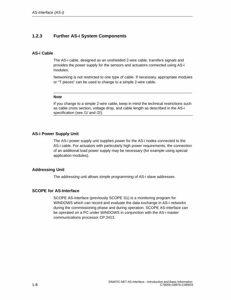
1.2.3 Further AS-i System Components
AS-i Cable
The AS-i cable, designed as an unshielded 2-wire cable, transfers signals andprovides the power supply for the sensors and actuators connected using AS-imodules.
Networking is not restricted to one type of cable. If necessary, appropriate modulesor “T pieces” can be used to change to a simple 2-wire cable.
Note
If you change to a simple 2-wire cable, keep in mind the technical restrictions suchas cable cross section, voltage drop, and cable length as described in the AS-ispecification (see /1/ and /2/).
AS-i Power Supply Unit
The AS-i power supply unit supplies power for the AS-i nodes connected to theAS-i cable. For actuators with particularly high power requirements, the connectionof an additional load power supply may be necessary (for example using specialapplication modules).
Addressing Unit
The addressing unit allows simple programming of AS-i slave addresses.
SCOPE for AS-Interface
SCOPE AS-interface (previously SCOPE S1) is a monitoring program forWINDOWS which can record and evaluate the data exchange in AS-i networksduring the commissioning phase and during operation. SCOPE AS-interface canbe operated on a PC under WINDOWS in conjunction with the AS-i mastercommunications processor CP 2413.

AS-Interface (AS-i)
1-9SIMATIC NET AS-Interface – Introduction and Basic InformationC79000-G8976-C089/03
1.3 System Characteristics and Important Data
How the AS-Interface Functions
The AS-Interface/AS-i system operates as outlined below:
� Master-slave access techniques
The AS-i interface is a “single master system”. This means that there is onlyone master per AS-i network which controls the data exchange. This polls allAS-i slaves one after the other and waits for a response.
� Electronic address setting
The address of an AS-i slave is its identifier. This only occurs once within anAS-Interface system. The setting can either be made using a specialaddressing unit or by an AS-i master. The address is always storedpermanently on the AS-i slave. When they are supplied, the AS-i slaves alwayshave the address “0”.
� Operating reliability and flexibility
The transmission technique used (current modulation) guarantees highoperating reliability. The master monitors the voltage on the cable and thetransferred data. It detects transmission errors and the failure of slaves andsends a message to the PLC. The user can then react to this message.
Replacing or adding AS-i slaves during normal operation does not affectcommunication with other AS-i slaves.
Physical Characteristics
The most important physical characteristics of the AS-Interface and itscomponents are as follows:
� 2-wire cable for data and power supply
A simple 2-wire cable with a cross section of 2 x 1.5 mm2 can be used.Shielding or twisting is not necessary. Both the data and the power aretransferred on this cable. The power available depends on the AS-i powersupply unit used.
For optimum wiring, the mechanically coded AS-i cable is available preventingthe connections being reversed and making simple contact with the AS-iapplication modules using the penetration technique.
� Tree structure network with a cable length up to 100 m
The “tree structure” of the AS-Interface allows any point on a cable section tobe used as the start of a new branch. The total length of all subsections can beup to 100 m.
� Direct integration
Practically all the electronics required for a slave have been integrated on aspecial IC. This allows the AS-i connector to be integrated directly in binaryactuators or sensors. All the required components can be installed within a

AS-Interface (AS-i)
1-10SIMATIC NET AS-Interface – Introduction and Basic Information
C79000-G8976-C089/03
space of approximately 2 cm3.
� Increased functionality, more uses for the customer
Direct integration allows devices to be equipped with a wide range of functions.Four data and four parameter lines are available. The resulting “intelligent”actuators/sensors increase the possibilities, for example, monitoring, parameterassignment, wear or pollution checks etc.
� Additional power supply for higher power requirements
An external source of power can be provided for slaves with a higher powerrequirement (see /1/).
System Limits
� Cycle time
– max. 5 ms with standard AS-i slaves
– max. 10 ms with AS-i slaves using the extended addressing mode
AS-i uses constant message lengths. Complicated procedures for controllingtransmission and identifying message lengths or data formats are notrequired. This makes it possible for a master to poll all connected standardslaves within a maximum of 5 ms and to update the data both on the masterand slave.
If only one AS-i slave using the extended addressing mode is located at anaddress, this slave is polled at least every 5 ms. If two extended slaves (Aand B slave) share an address, the maximum polling cycle is 10 ms. (Bslaves can only be connected to extended masters.)
� Number of connectable AS-i slaves
– Maximum of 31 standard slaves
– Maximum of 62 slaves with the extended addressing mode
AS-i slaves are the input and output channels of AS-i system. They are onlyactive when called by the AS-i master. They trigger actions or transmitreactions to the master when commanded.
Each AS-i slave is identified by its own address (1 to 31). A maximum of 62slaves using the extended addressing mode can be connected to anextended master. Pairs of slaves using the extended addressing modeoccupy one address; in other words, the addresses 1 to 31 can be assignedto two extended slaves.
If standard slaves are connected to an extended master, these occupy acomplete address; in other words, a maximum of up to 31 standard slavescan be connected to an extended master.
� Number of inputs/outputs
– A maximum of 248 binary inputs and outputs with standard modules
– A maximum of 248 inputs/186 outputs with modules using theextended addressing mode
Each standard AS-i slave can receive 4 bits of data and send 4 bits of data.

AS-Interface (AS-i)
1-11SIMATIC NET AS-Interface – Introduction and Basic InformationC79000-G8976-C089/03
Special modules allow each of these bits to be used for a binary actuator ora binary sensor. This means that an AS-i cable with standard AS-i slavescan have a maximum of 248 binary attachments (124 inputs and 124outputs). All typical actuators or sensors can be connected to theAS-interface in this way. The modules are used as distributed inputs/outputs.
If modules with the extended addressing mode are used, a maximum of 3inputs and 3 outputs is available per module; in other words a maximum of248 inputs and 186 outputs can be operated with modules using theextended addressing mode.
Range of Functions of the Master Modules
The functions of the AS-i master modules are stipulated in the AS-i masterspecification (see /1/ and /2/). An overview of these functions can be found in thePICS in the appendix of the master module manual.
�

AS-Interface (AS-i)
1-12SIMATIC NET AS-Interface – Introduction and Basic Information
C79000-G8976-C089/03
2-1SIMATIC NET AS-Interface – Introduction and Basic InformationC79000-G8976-C089/03
The AS-i Masters
AS-Interface is a single-master system. For SIMATIC systems, there arecommunications processors (CPs) that control the process or field communicationas the AS-i masters.
These also include gateways that operate like an AS-i master and allow access tothe actuators and sensors, for example, of PROFIBUS DP.
This chapter introduces you to these AS-i system components. For more detailedinformation on handling, configuring, and programming, refer to the manual of therelevant device.
2

The AS-i Masters
2-2SIMATIC NET AS-Interface – Introduction and Basic Information
C79000-G8976-C089/03
2.1 AS-i Masters for the SIMATIC S7-200
CP 242-2 (Standard AS-i Master)
The CP 242-2 module allows the connection of an AS-i chain to the S7-200programmable logic controller. The CP 242-2 provides the complete functionality ofthe AS-i master specification for standard AS-i masters (profile M1).
Branch
(with integratedAS-i connection)
AS-i cable
S7-200 CPU
SIMATICS7–200
CPU 212SIEMENS
CP 242-2AS-i master
Passive moduleActive module
AS-i power supply
Actuator/sensor(with integratedAS-i connection)
(without integratedAS-i connection)
Figure 2-1
CP 243-2 (Extended AS-i Master)
The CP 243-2 module allows connection of an AS-i chain to the new S7-200 series(CPU 222, CPU 224, etc.). The CP 243-2 is an extended master complying withprofile M1e; in other words, it covers the complete functionality of the AS-i masterspecification for extended AS-i masters.

The AS-i Masters
2-3SIMATIC NET AS-Interface – Introduction and Basic InformationC79000-G8976-C089/03
CP 242-8 (Standard AS-i Master)
The CP 242-8 has not only the functions of the CP 242-2 but also a connection toPROFIBUS DP (DP slave). This allows the cost-effective connection of an S7-200to PROFIBUS DP and the AS-Interface at the same time.
Branch
Active modulePassive module
AS-i cable
Actuator/sensor
S7-200 CPU
AS-i master/DP slave
Q0.0Q0.1Q0.2Q0.3Q0.4Q0.5
I 0.0I 0.1I 0.2I 0.3I 0.4I 0.5I 0.6I 0.7
SFRUNSTOP
SIMATICS7–200
SIEMENS
CP 242–8
Wider ranging network via PROFIBUS DP
SF
APF
CERAUP
CM
AS-InterfaceMaster
CP 242-2
6GK7 242-2AX00-0XA0
12
3
4
5
6
7
8
0
9
10
11
12
13
14
15
16
17
18
19
20
21
22
23
24
25
26
27
28
29
30
31 X 23 4
AS-i power supply
(with integratedAS-i connection)(without integrated
AS-i connection)
(with integratedAS-i connection)
Figure 2-2

The AS-i Masters
2-4SIMATIC NET AS-Interface – Introduction and Basic Information
C79000-G8976-C089/03
2.2 AS-i Masters for the SIMATIC S7-300
CP 342-2 (Standard AS-i Master)
The CP 342-2 is available as the standard AS-i master module for controllers ofthe S7-300 range and for the ET 200M distributed I/O system.
The CP 342-2 occupies 16 input and 16 output bytes in the analog area of thecontroller via which the input data of the slaves can be read and the output data ofthe slaves can be set.
When using an FC, in addition to the I/O data exchange, it is also possible toexecute master calls from within the control program. The FC is supplied on adiskette along with the manual for the CP 342-2.
(4 x slave)
= Slave ASIC
Actuator or sensorwith direct connection
S7-300
CP 342-2 / 343-2
AS-i powersupply unit
AS-i cable
Passive AS-i application module
Binary sensors and actuatorsBinary sensors and actuators
AS-i application module
Branch of theAS-i cable
Active AS-i application module(with slave ASIC)
Active or passive(with integratedAS-i connection)
(without integratedAS-i connection)
(without integrated AS-i connection)
Figure 2-3
The AS-i Masters
2-5SIMATIC NET AS-Interface – Introduction and Basic InformationC79000-G8976-C089/03
CP 343-2 (Extended AS-i Master)
The CP 343-2 is an extended AS-i master for S7-300 series controllers and the ET200 M distributed I/O system.
The CP 343-2 occupies 16 input and 16 output bytes in the analog area of thecontroller via which the AS-i standard slaves and AS-i A slaves can be addressed.AS-i B slaves have an additional I/O area that is accessible using SFCs.
When using an FC, in addition to the I/O data exchange, it is also possible toexecute master calls from within the control program. The FC is supplied on adiskette along with the manual for the CP 343-2.

The AS-i Masters
2-6SIMATIC NET AS-Interface – Introduction and Basic Information
C79000-G8976-C089/03
2.3 AS-i Master for SIMATIC S5 PLCs in the HigherPerformance Range
CP 2430 (Standard AS-i Master)
The CP 2430 is available as a master module (AS-i standard master) forprogrammable controllers of the S5-115U, S5-135U, S5-155U series.
The CP 2430 is a double master that can operate two independent AS-i networkseach with a maximum of 31 slaves.
If required, the AS-i master can be used like an I/O module in the PLC to addressthe input and output data of the AS-i slaves. In the address area of the PLC, itoccupies 16 input and 16 output bytes per AS-i chain, in other words a total of 32input bytes and 32 output bytes. In terms of programming the PLC, there is nodifference between an AS-i master and standard I/O modules. The software onlyneeds a minimum of adaptation.
If handling blocks are used, the full range of functions according to the AS-i masterspecification is available. As an option, the I/O data can also be transferred to theCP 2430 using handling blocks. In this case, the CP 2430 does not occupy anyspace in the I/O address area of the controller.
(4 x slave)
= slave ASIC
AS-i power
supply unit
Segment B
Segment A
CP 2430
AS-i cable
Active AS-Interfaceapplication module(with slave ASIC)
Passive AS-Interface application module
Binary sensors and actuatorsBinary sensors and actuators
Active or passiveAS-Interface user module
Actuator or sensor
with direct
connection
Branch of the
AS-i cable
SIMATIC NET Industrial Ethernet
or
SIMATIC NET PROFIBUS
AS-i cable
(with integratedAS-i connection)
(without integrated AS-i connection)
(without integratedAS-i connection)
Figure 2-4 Example of a SIMATIC S5 System Configuration with the CP 2430

The AS-i Masters
2-7SIMATIC NET AS-Interface – Introduction and Basic InformationC79000-G8976-C089/03
2.4 AS-i Master for SIMATIC S5 PLCs in the LowerPerformance Range
CP 2433 (Standard AS-i Master)
The CP 2433 is available as a master module (AS-i standard master) forprogrammable controllers of the S5-90U, S5-95U, S5-100U series and the ET200U distributed I/O system.
The AS-i master is used like an I/O module in the PLC to address the input andoutput data of the AS-i slaves. In the address area of the PLC, it occupies 16 inputbytes and 16 output bytes. When programming the PLC, the user does not seeany difference between an AS-i master and standard I/O modules. The softwareonly needs a minimum of adaptation.
If a function block is used, the complete range of functions according to the AS-imaster specification is available. This function block is available for the SIMATICS5-95U and S5-100U / CPU 103 and is supplied on diskette with the manual forthe CP 2433.
The CP 2433 occupies a double slot on the bus bar.
CP 2433
Binary sensors and actuators
Binary sensors and actuators
Branch of theActive or passive
(4 x slave)
= Slave ASIC
Actuator or sensorwith directconnection
AS-ipowersupplyunit
S5-95U
Passive AS-i moduleActive AS-i module
AS-i cable
AS-i moduleAS-i cable
(with integratedAS-i connection)
(without integratedAS-i connection)
(with integratedAS-i connection)
(without integratedAS-i connection)
Figure 2-5 Example of a SIMATIC S5 PLC with the CP 2433

The AS-i Masters
2-8SIMATIC NET AS-Interface – Introduction and Basic Information
C79000-G8976-C089/03
2.5 AS-i Gateways
DP / AS-i Gateway
Even when using the PROFIBUS DP distributed I/Os, the use of AS-Interface canhave advantages. The networking of the process peripherals can be extendedbeyond PROFIBUS to include the actuators/sensors.
The following devices can be used as gateways to PROFIBUS:
� DP/AS-Interface Link 20 (a link designed in compliance with IP 20 forinterfacing AS-Interface to PROFIBUS DP)
� DP/AS-Interface Link 20E (link designed in compliance with IP 20 with extendedAS-i master functionality for interfacing AS-Interface to PROFIBUS-DP)
� CP 242-8 (simultaneous connection of an S7-200 to PROFIBUS DP andAS-Interface)
� CP 142-2 in the ET 200X
� CP 342-2 in the ET 200M
� CP 343-2 in the ET 200M (extended master)
� CP 2433 in the ET 200U
� S5-95U PLC with PROFIBUS interface and CP 2433
� S7-300 / CPU 315-2 DP with CP 342-2 or DP343-2
� DP/AS-Interface Link (link designed in compliance with IP 65 for connecting theAS-Interface to PROFIBUS DP)

The AS-i Masters
2-9SIMATIC NET AS-Interface – Introduction and Basic InformationC79000-G8976-C089/03
AS-i distributor
AS-i power supply
Active modulePassive module
AS-i cable
Actuator/sensor
Wider ranging network via PROFIBUS DP
SF
APF
CERAUP
CM6GK7 1415 2AA0
1
2
3
4
5
6
7
8
0
9
10
11
12
13
14
15
16
17
18
19
20
21
22
23
24
25
26
27
28
29
30
31 X 23 4
DIA
ADRBF DP-AS-Interface
Link 20
DP/AS-Interface Link 20 E
(with integratedAS-i connection)
(without integratedAS-i connection)
(with integratedAS-i connection)
Figure 2-6 Example of a System Configuration with the DP/AS-Interface Link 20

The AS-i Masters
2-10SIMATIC NET AS-Interface – Introduction and Basic Information
C79000-G8976-C089/03
2.6 AS-i Master for ET 200X
CP 142-2 (Standard AS-i Master)
The CP 142-2 module (AS-i standard master) can be operated in the ET 200Xdistributed I/O system. It allows the connection of an AS-i chain to the I/O device.The special feature of the ET 200X distributed I/O system is its ruggedconstruction complying with IP 65, IP 66 and IP 67.
(4 x slave)
PROFIBUSPROFIBUS-DP master
Roundcable
AS-i cable
Passive AS-i application module Active AS-i application module
Binary sensors and actuators(without slave ASIC)
Active or passive AS-iapplication module
Binary sensorsand actuators(with slave ASIC)
Actuator or sensor withdirect connection
Branch of theAS-i cable= slave ASIC
AS-i powersupply unit
CP 142-2
ET 200 X
PROFIBUS
(without integratedAS-i connection)
(with integrated AS-i connection)
Figure 2-7 Example of an ET 200X with CP 142-2

The AS-i Masters
2-11SIMATIC NET AS-Interface – Introduction and Basic InformationC79000-G8976-C089/03
2.7 AS-i Master for PC-AT
CP 2413 (Standard AS-i Master)
The CP 2413 (AS-i standard master) allows the attachment of AS-Interface toPCs.
The hardware of the AS-i master is implemented as a short PC-AT card. Up to fourAS-i master CPs can be operated at the same time in one PC. This means that theSiemens AS-i PC master is also suitable for complex control tasks. The firmwarerunning on the PC master is loaded when the host is started up.
An operating and demonstration program is available which provides the currentstatus of the slaves on the cable and permits simple operation of the slaves. Thisprogram can also be used for diagnostic purposes; it also allows the programmingof the addresses of AS-i slaves.
Since not only the AS-i master card can be operated in a PC, but also PCinterfaces for the Industrial Ethernet and PROFIBUS bus at the same time, thedata supplied by the AS-i slaves can also be made available to other stations in thenetwork.
AS-i cable
(4 x slave)
= Slave ASIC
CP 2413
PROFIBUS or Industrial Ethernet
PC-ATAS-i powersupply unit
Actuator or sensorwith direct connection Active AS-i module
Active AS-i module
Binary sensors and actuatorswithout slave ASICBinary sensors and actuators
with slave ASIC Active or passive AS-imodule
Branch of theAS-i cable
(without integratedAS-i connection) (with integrated
AS-i connection)
Figure 2-8 Example of a System Configuration with PC-AT and CP 2413

The AS-i Masters
2-12SIMATIC NET AS-Interface – Introduction and Basic Information
C79000-G8976-C089/03
Library for Integrating the AS-i Functions
There are masters and libraries for C and Visual Basic applications for the masterunder MS-DOS and Windows. These functions are described in the “CP 2413 AS-iMaster Module” manual.
�

3-1SIMATIC NET AS-Interface – Introduction and Basic InformationC79000-G8976-C089/03
Further AS-i System Components
As well as the AS-i masters described in this manual, the components of the AS-itransmission system and the AS-i slaves are also required on the AS-Interface.
The following sections provide an overview of the basic characteristics andinteraction of these components.
Due to the continuing development of new AS-i system components, a completepresentation of all the currently available components is not possible. Refer to theavailable system catalogs and ask your Siemens office for more information.
3

Further AS-i System Components
3-2SIMATIC NET AS-Interface – Introduction and Basic Information
C79000-G8976-C089/03
3.1 The AS-i Cable
Design and Advantages
The AS-i cable (shaped cable) allows simple and fast installation of an AS-isystem. The AS-i cable is a rubberized 2-wire cable (2 x 1.5 mm2). The profilesection prevents stations being connected with incorrect polarity.
The AS-i cable is contacted using the penetration technique. Contact bladespenetrate the rubber jacket and make contact with the two wires. Thisguarantees a low contact resistance andensures a reliable data connection. The cabledoes not need to be cut, have its insulationremoved or be screwed down. For this type ofconnection, there are coupling modulesdesigned for the penetration technique.
The jacket of the AS-i cable is rubber. If modules need to be moved after theyhave been connected to the AS-i cable this is possible without causing anyproblems. The AS-i cable is “self-healing”. This means that the holes made by thecontact blades in the rubber jacket of the cable close themselves and revert to thetype of protection IP67. When the cable is installed in an AS-i module, the cableseals the openings. The type of protection IP67 is therefore achieved.
Use of Other 2-Wire Cables
Apart from the special AS-i cable, any 2-wire cable with a cross-section of 2 x 1.5mm2 can be used. Shielding or twisting is not necessary. For the transition fromthe special AS-i cable to a different cable (e.g. a standard round cable) there is aspecial module available without integrated electronics (transition from the AS-icable to four M12 connectors and transition from the AS-i cable to one M12connector).
10 mm
6,5 mm
4 mm

Further AS-i System Components
3-3SIMATIC NET AS-Interface – Introduction and Basic InformationC79000-G8976-C089/03
3.2 AS-i Modules: Blocks of the AS-i Slaves
Concept
Within the AS-i system, the AS-i modules can be compared with input and outputmodules. Along with the actuators and sensors they make up the AS-i slaves andconnect the slaves to the AS-i master. The actuators/sensors are connected viaM12 connectors. The pinout corresponds to DIN IEC 947 5-2. The modules withdimensions of approximately 45 x 45 x 80 mm are used locally on the machineitself. They are connected via the AS-i cable and have the degree of protectionIP67.
Active and Passive Modules
The following modules must be distinguished:
� The active AS-i module with integrated AS-i chip Using this, conventional sensors and actuators can be connected. Every normalactuator or sensor can therefore be networked via AS-i.
� The passive AS-i moduleThis does not contain its own electronics and allows the connection of AS-isensors and actuators with integrated AS-i chips.
In keeping with the concept of the standard AS-i master and the extended AS-imaster (see Section 1.2), either AS-i chips with standard functions or withextended functions are used.
The modules are designed so that a uniform electromechanical interface to theAS-i cable can be created. This is achieved with the uniform lower section of themodule, which is therefore also known as a coupling module.
Specially constructed upper module sections, also known as application modulesare also available. The variations in the module components range from the simplecover for branching the AS-i cable to application modules with integrated AS-ichips for connecting up to four conventional sensors or actuators.

Further AS-i System Components
3-4SIMATIC NET AS-Interface – Introduction and Basic Information
C79000-G8976-C089/03
Example:
The following diagram illustrates an active AS-i module for four connections.
Standard rail 35mm
lower section(coupling module)
Upper section
M12 connectorforactuator/sensor
Application module operatingindicator
Operating indicator of theactuator/sensorswitching signal
AS-i cable
(application module)
Figure 3-1
Note
Please ask your local sales office or distributor about other AS-i modules (forexample 4I/4O module).
Further AS-i System Components
3-5SIMATIC NET AS-Interface – Introduction and Basic InformationC79000-G8976-C089/03
3.3 Installing an AS-i Module
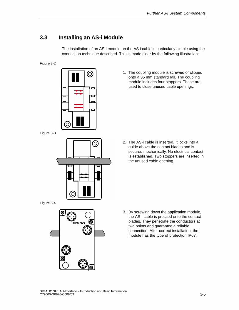
The installation of an AS-i module on the AS-i cable is particularly simple using theconnection technique described. This is made clear by the following illustration:
Figure 3-2
1. The coupling module is screwed or clippedonto a 35 mm standard rail. The couplingmodule includes four stoppers. These areused to close unused cable openings.
Figure 3-3
2. The AS-i cable is inserted. It locks into aguide above the contact blades and issecured mechanically. No electrical contactis established. Two stoppers are inserted inthe unused cable opening.
Figure 3-4
3. By screwing down the application module,the AS-i cable is pressed onto the contactblades. They penetrate the conductors attwo points and guarantee a reliableconnection. After correct installation, themodule has the type of protection IP67.

Further AS-i System Components
3-6SIMATIC NET AS-Interface – Introduction and Basic Information
C79000-G8976-C089/03
3.4 AS-Interface Repeater / Extender
Area of Application
The AS interface repeater and extender is intended for use in an actuator-sensorinterface environment.
The device is used to extend the maximum possible length of the AS-interface of100 m. An existing 100 m segment can be extended by a maximum of two further100 m segments.
Using the Repeater
The AS-interface repeater is used when slaves must be operated on all cablesegments. A separate AS-interface power supply unit is then required for eachAS-interface segment (before and after the repeater). The repeater has thefollowing features:
� Extends the cable length to a maximum of 300m.
� Slaves can be used on both sides of the repeater.
� A power supply unit is required on both sides of the AS interface.
� Electrical isolation of the two cables.
� Separate indication of the correct voltage for each side.
� Installation in standard application module casing.

Further AS-i System Components
3-7SIMATIC NET AS-Interface – Introduction and Basic InformationC79000-G8976-C089/03
Master
max. 100 m AS-Interface cable max. 100 m AS-Interface cable
AS-Interface powersupply unit
AS-Interface powersupply unit
Repeater
302010
9876
543210
SINIC S16GK1 243–3SA00
1 2 3 4 5 6
7
8
9+
10
ACTIVE SLAVESCP FAULT
RUN
S1 POWER FAIL
CONFIG ERROR
AUTOPROG
CONFIG MODE
SET CONFIG
CHANGE MODE
CP 2433
21 3456L1N
ASI+ASI–
S I I M I N S
POWIR SUPPLYASI +ASI –Schirm
Schirm
21 3456L1N
ASI+ASI–
S I I M I N S
POWIR SUPPLYASI +ASI –Schirm
Schirm
Figure 3-5 Using the Repeater

Further AS-i System Components
3-8SIMATIC NET AS-Interface – Introduction and Basic Information
C79000-G8976-C089/03
Using the Extender
The AS-Interface extender is used in applications in which the master is installed ata greater distance from the actual AS-Interface installation:
� Masters can be located up to 100 m from the AS-interface segment.
� Slaves can only be used on the side of the extender away from the master.
� Power supply is only required on the side away from the master.
� No electrical isolation of the two cables.
� Indication of the correct voltage.
� Installed in standard application module casing. The extender is mounted onthe FK-E coupling module.
Master
max. 100m AS-Interface cable max. 100 m AS-Interface cable
AS-Interface powersupply unit
Extender
302010
9876
543210
SINIC S16GK1 243–3SA00
1 2 3 4 5 6
7
8
9+
10
ACTIVE SLAVESCP FAULT
RUN
S1 POWER FAIL
CONFIG ERROR
AUTOPROG
CONFIG MODE
SET CONFIG
CHANGE MODE
CP 2433
21 3456L1N
ASI+ASI–
S I I M I N S
POWIR SUPPLYASI +ASI –Schirm
Schirm
Figure 3-6 Using the Extender

Further AS-i System Components
3-9SIMATIC NET AS-Interface – Introduction and Basic InformationC79000-G8976-C089/03
3.5 Addressing Unit
Area of Application
Each slave on the AS-i requires an address. This address is saved on the slave.You can program the address of a slave using the addressing unit.
Handling
To program a module (application module), it is plugged in to the special adapteron the addressing unit. The stored address is displayed on the unit when you pressthe ADR button. The new address is set using the arrow buttons. After pressingthe PRG button, the new address is saved on the application module (slave).
Addressing intelligent sensors/actuators is the same as with application modules.The sensor/actuators are connected to the addressing unit via an M12 connector.The addressing unit has an integrated M12 socket for this purpose.
The addressing unit is supplied by integrated batteries that can be charged usingan external power unit. When not in use, the unit switches off automatically after aperiod of time.
3RX9400–0AA00
ADR
PRG
Adresse+
Adresse–
Programmieren
Lesen/I in
M12 socket
Adapter
Address setter extremely simple operation
Integrated adapter suitable for application modules
Attachment also possible via M 12(Sonar Bero)
Figure 3-7

Further AS-i System Components
3-10SIMATIC NET AS-Interface – Introduction and Basic Information
C79000-G8976-C089/03
3.6 SCOPE Diagnostic Software for AS-Interface
Area of Application
The SCOPE diagnostic software for the AS-Interface is a monitoring programcapable of recording and evaluating the data exchange in AS-i networks duringinstallation and operation. SCOPE for AS-interface can be operated on a PC underWINDOWS in conjunction with the AS-i master communications processor CP2413.
The software is operated using the known WINDOWS conventions. The completerange of functions can be found in the SIMATIC NET catalog /3/ and the productmanual.
Functions
SCOPE for AS-interface provides the following functions:
� Online display of all master and slave user data in overview (data monitor);
� Monitoring of slave activities
� Online display of essential statistical values of data exchange on the bus;
� Trigger and filter functions for recording;
� Recording of the entire data exchange in a ring buffer;
� Documentation functions. �

4-1SIMATIC NET AS-Interface – Introduction and Basic InformationC79000-G8976-C089/03
The Master Mode – Commands, Sequence,Programming
The tasks and functions of an AS-i master are described below.
This section is important for understanding the functions, modes and interfacesavailable with the AS-i master modules. These functions and interfaces aredescribed in detail in the manuals of the individual CPs.
For further information refer to /1/
4

The Master Mode – Commands, Sequence, Programming
4-2SIMATIC NET AS-Interface – Introduction and Basic Information
C79000-G8976-C089/03
4.1 Master-Slave Principle
How the AS-Interface Operates
The AS-Interface operates on the master-slave principle. This means that the AS-imaster connected to the AS-i cable controls the data exchange with the slaves viathe interface to the AS-i cable.
The following diagram illustrates the two interfaces of the AS-i master CP.
� The process data and parameter assignment commands are transferred via theinterface between the master CPU and the master CP.
The user programs have suitable function calls and mechanisms available forreading and writing via this interface.
� Information is exchanged with the AS-i slaves via the interface between themaster CP and AS-i cable.
PLC / PC
CPU
I/O
Configuration
Address
AS-i cable
AS-i slave
Userprogram
AS-i masterCP
Interface to the userprogram
Para-meters
Figure 4-1

The Master Mode – Commands, Sequence, Programming
4-3SIMATIC NET AS-Interface – Introduction and Basic InformationC79000-G8976-C089/03
4.1.1 Tasks and Functions of the AS-i Master
Graded Range of Performance – Use of Profiles According to the AS-iSpecification
The AS-i master specification distinguishes masters with different ranges offunctions known as a “profile”.
For standard AS-i masters and extended AS-i masters there are three differentmaster classes (M0, M1, M2 for standard masters, M0e, M1e, M2e for extendedmasters). The AS-i specification stipulates which functions a master in a particularclass must be able to perform (refer also to the PICS in the appendix of the manualfor the particular CP).
The profiles have the following practical significance:
� Master profile M0 / M0e:
The AS-i master can exchange I/O data with the individual AS-i slaves. Themaster is configured by using the station configuration found on the cableknown as the “expected configuration”.
� Master profile M1 / M1e :
This profile covers all the functions according to the AS-i master specification.
� Master profile M2 / M2e:
The functionality of this profile corresponds to master profile M0/M0e, but in thisprofile the AS-i master can also assign parameters to the AS-i slaves.
The essential difference between extended AS-i masters and standard AS-imasters is that they support the attachment of up to 62 AS-i slaves using theextended addressing mode. Extended AS-i masters from SIMATIC NET alsoprovide particularly simple access for AS-Interface analog slaves complying withprofile 7.3/7.4.
Note
If you decide to use standard operation (master profile M0), you can skip theremaining sections in this chapter. Continue reading in the manual of your CP tofind out the steps required for installation and operating the module.

The Master Mode – Commands, Sequence, Programming
4-4SIMATIC NET AS-Interface – Introduction and Basic Information
C79000-G8976-C089/03
4.1.2 How an AS-i Slave Functions
Connecting to the AS-i Cable
The AS-i slave has an integrated circuit (AS-i chip; see also Section 3.2) thatprovides the attachment of an AS-i device (sensor/actuator) to the common buscable to the AS-i master. The integrated circuit contains the following components:
� 4 configurable data inputs and outputs
� 4 parameter outputs
The operating parameters, configuration data with I/O assignment, identificationcode, and slave address are stored in additional memory (for example EEPROM).
I/O Data
The useful data for the automation components that were transferred from the AS-imaster to the AS-i slave are available at the data outputs. The values at the datainputs are made available to the AS-i master when the AS-i slave is polled.
Parameter
Using the parameter outputs of the AS-i slave, the AS-i master can transfer valuesthat are not interpreted as simple data. These parameter values can be used tocontrol and switch over between internal operating modes of the sensors oractuators. It could, for example, be possible to update a calibration value duringvarious operating phases. This function is possible with slaves with an integratedAS-i connection providing they support the function in question.
Configuration
The input/output configuration (I/O configuration) indicates which data lines of theAS-i slave are used as inputs, outputs or as bidirectional outputs. The I/Oconfiguration (4 bits) can be found in the description of the AS-i slave (an overviewof codings can be found in /1/).
In addition to the I/O configuration, the type of the AS-i slave is described by anidentification code, and with newer AS-Interface slaves by three identificationcodes (ID code, ID1 code, ID2 code).
For more detailed information on the ID codes, refer to the manufacturer’sdescription.

The Master Mode – Commands, Sequence, Programming
4-5SIMATIC NET AS-Interface – Introduction and Basic InformationC79000-G8976-C089/03
4.2 Data Transfer
Information/Data Structure
Before introducing you to the operating phases and the functions during theseoperating phases, a brief outline of the information structure of the AS-imaster/slave system is necessary.
In the following diagram, the data fields and lists of the system are configured inthe system structure diagram you saw in the previous section.
PLC / PC AS-islave
CPU
I/O data
Parameters
Configuration data
Act. params.
Act. configurationdata
LDS
LAS
Data images
Config. data(EEPROM)
Parameters
LPS
Exp. configurationdata
I/O data
Address
Userprogram
AS-i master CP
Figure 4-2
The following structures are found on the AS-i master:
� Data images
These contain temporarily stored information:
– Actual parameters
The actual parameters are an image of the parameters currently on the AS-islave.
– Actual configuration data
The actual configuration data field contains the I/O configurations and IDcodes of all connected AS-i slaves once these data have been read from theAS-i slaves.
– The list of detected AS-i slaves (LDS)
The LDS specifies which AS-i slaves were detected on the AS-i bus.

The Master Mode – Commands, Sequence, Programming
4-6SIMATIC NET AS-Interface – Introduction and Basic Information
C79000-G8976-C089/03
– The list of activated AS-i slaves (LAS)
The LAS specifies which AS-i slaves were activated by the AS-i master. I/Odata are only exchanged with activated AS-i slaves.
� I/O data
The process input and output data.
� Configuration data
These are non-volatile data (e.g. stored in an EEPROM), which are availableunchanged even following a power failure.
– Expected configuration data
These are selectable comparison values which allow the configuration dataof the detected AS-i slaves to be checked.
– List of permanent AS-i slaves (LPS)
This list specifies the AS-i slaves expected on the AS-i cable by the AS-imaster. The AS-i master checks continuously whether all the AS-i slavesspecified in the LPS exist and whether their configuration data match theexpected configuration data.
The AS-i slave has the following structures:
� I/O data
� Parameters
� Actual configuration data
The configuration data include the I/O configuration and the ID codes of theAS-i slave.
� Address
The AS-i slaves have address “0” when installed. To allow a data exchange, theAS-i slaves must be programmed with addresses other than “0”. The address“0” is reserved for special functions.

The Master Mode – Commands, Sequence, Programming
4-7SIMATIC NET AS-Interface – Introduction and Basic InformationC79000-G8976-C089/03
4.2.1 The Operating Phases
The following diagram illustrates the individual operating phases.
Initialization
Detection PhaseStartupPhase
Data Exchange PhaseNormal operation
Management Phase
Inclusion Phase
Offline phase
Activation phase in theprotected mode”Startup with configureddata”
Activation phase in theconfiguration mode
”Startup without configureddata/obtain configuration data”
Figure 4-3

The Master Mode – Commands, Sequence, Programming
4-8SIMATIC NET AS-Interface – Introduction and Basic Information
C79000-G8976-C089/03
Initialization mode
The initialization mode, also known as the offline phase, sets the basic status ofthe master. The module is initialized after switching on the power supply orfollowing a restart during operation. During the initialization, the images of all theslave inputs and the output data from the point of view of the application are set tothe value “0” (inactive).
After switching on the power supply, the configured parameters are copied to theparameters field so that the subsequent activation uses the preset parameters. Ifthe AS-i master is reinitialized during operation, the values from the parametersfield which may have changed in the meantime are retained.
Startup Phase
� Detection phase: Detection of AS-i slaves in the startup phase
During startup or after a reset, the AS-i master runs through a startup phaseduring which it detects which AS-i slaves are connected to the AS-i cable andwhat type these slaves are. The “Type” of the slaves is specified by theconfiguration data stored permanently on the AS-i slave when it ismanufactured and can be queried by the master. Configuration files contain theI/O assignment of an AS-i slave and the slave type (ID codes).
The master enters detected slaves in the list of detected slaves (LDS).
� Activation phase: Activating AS-i slaves
After the AS-i slaves are detected, they are activated by the master sending aspecial call. When activating individual slaves, a distinction is made betweentwo modes on the AS-i master:
– Master in the configuration mode:
All detected stations (with the exception of the slave with address “0”) areactivated. In this mode, it is possible to read actual values and to store themfor a configuration (–> configuration mode).
– Master in the protected mode:
Only the stations corresponding to the expected configuration stored on theAS-i master are activated. If the actual configuration found on the AS-i cablediffers from this expected configuration, this is indicated by the AS-i master.
The master enters activated AS-i slaves in the list of activated slaves (LAS).
� Normal mode
On completion of the startup phase, the AS-i master switches to the normalmode.
– Data exchange phase
In the normal mode, the master sends cyclic data (output data) to theindividual AS-i slaves and receives their acknowledgment messages (input

The Master Mode – Commands, Sequence, Programming
4-9SIMATIC NET AS-Interface – Introduction and Basic InformationC79000-G8976-C089/03
data). If an error is detected during the transmission, the master repeats theappropriate poll.
– Management phase
During this phase, all existing jobs of the control application are processedand sent. Possible jobs are, for example, as follows:
Parameter transfer:
Four parameter bits (three parameter bits with AS-i slaves with the extendedaddressing mode) are transferred to a slave and are used, for example, for athreshold value setting.
Changing slave addresses:
This function allows the addresses of AS-i slaves to be changed by themaster if the AS-i slave supports this particular function.
– Inclusion phase
In the inclusion phase, newly added AS-i slaves are included in the list ofdetected AS-i slaves and providing the configuration mode is selected theyare also activated (with the exception of slaves with address “0”). If themaster is in the protected mode, only the slaves stored in the expectedconfiguration of the AS-i master are activated. With this mechanism, slavesthat were temporarily out of service are also included again.

The Master Mode – Commands, Sequence, Programming
4-10SIMATIC NET AS-Interface – Introduction and Basic Information
C79000-G8976-C089/03
4.2.2 Interface Functions
To control the master/slave interaction from the user program, there are variousfunctions available on the interface. The possibilities are explained based on theillustration below. Here, simply the possible operations and the direction of dataflow are illustrated.
AS-i master AS-i slave
Userprogram
Process imageI/O data
CPU CP
I/O data
Parameters
Configuration data
Act. params.
Act. configurationdata
LDS
LAS
Data images
Config. data(EEPROM)
Parameters
LAS
Exp. configurationdata
1. read/write
2.
Read / storeconfigurationdata
3.Configure actual
4. Supply slaves withconfigured parameters(activation)
I/O data
Figure 4-4
1. Read/write
When writing, parameters are transferred to the slave and the parameterimages on the CP; when reading, parameters are transferred from the slave orfrom the CP parameter image to the CPU.
2. Read and store (configured) configuration data
Configured parameters or configuration data are read from the non-volatilememory of the CP.
3. Configure actual
When reading, the parameters and configuration data are read from the slaveand stored permanently on the CP. When writing, parameters and configurationdata are stored permanently on the CP.
4. Supply slaves with configured parameters
Configured parameters are transferred from the non-volatile area of the CP tothe slaves.

The Master Mode – Commands, Sequence, Programming
4-11SIMATIC NET AS-Interface – Introduction and Basic InformationC79000-G8976-C089/03
4.2.3 Operating Extended AS-i Slaves with Standard AS-i Masters
Note
Please note the following information about operating extended AS-i slaves withstandard AS-i masters!
� If A slaves are connected to standard masters, make sure that the mostsignificant slave bit (bit 4) of each A slave is set to “0”. The most significantparameter bit (bit 4) must also be set to “1” (default value).
Without these settings, the A slave cannot be operated with a standard master.
� B slaves must not be connected to standard AS-Interface masters.
�

The Master Mode – Commands, Sequence, Programming
4-12SIMATIC NET AS-Interface – Introduction and Basic Information
C79000-G8976-C089/03

A-1SIMATIC NET AS-Interface – Introduction and Basic InformationC79000-G8976-C089/03
References
/1/
AS-Interface Das Aktuator-Sensor-Interface für die Automation
Werner Kriesel, O.W. Madelung, Carl Hanser Verlag München Wien 1994
/2/
AS-Interface Complete Specification
can be ordered from the AS-i Association e.V.
Address:
AS-International Association e.V.Geschäftsführung: Dr. Otto W. MadelungAuf den Broich 4AD – 51519 OdenthalGermany
Tel.: +49 – 2174 – 40756Fax.: +49 – 2174 – 41571
(The AS-i technology is promoted by the AS-Interface Association e. V.)
Internet address of the AS-International Association e.V.:
http://www.as-interface.com
/3/
SIMATIC NET Industrial Communications Networks
Catalog IK 10
The catalog can be ordered from your local SIEMENS branch office or distributor.
/4/
Profibus & AS-InterfaceComponents on the Field BusCatalog ST PI
The catalog can be ordered from your local SIEMENS branch office or distributor.
A

References
A-2SIMATIC NET AS-Interface – Introduction and Basic Information
C79000-G8976-C089/03
/5/
SIMATIC NET Industrial Communications Networks PROFIBUS NetworksManual Siemens AG
/6/
PROFIBUS standard EN 50170
Order numbers
The order numbers of the SIEMENS documentation listed above can be found inthe catalogs “SIMATIC NET Industrial Communication, Catalog IK10” and“SIMATIC Programmable Controllers SIMATIC S7 / M7 / C7”.
You can order these catalogs and obtain additional information from your localSIEMENS branch or distributor.
�

B-1SIMATIC NET AS-Interface – Introduction and Basic InformationC79000-G8976-C089/03
Glossary
APFAS-i Power Fail. Flag or LED display that indicates that the power supply on theAS-i cable is too low or has failed (for example failure of the AS-i power supplyunit).
AS-i (AS-Interface)Actuator-sensor interface. A network system for the lowest field area of theautomation range. It is suitable for networking sensors and actuators with controldevices. (previously: SINEC S1)
AS-i A/B slaveAS-i A/B slaves use the extended addressing mode. Pairs of A/B slaves can beassigned to one address on the AS-Interface; by organizing addresses in thisway, up to 62 AS-i A/B slaves can be attached to the AS-Interface.
AS-i analog slaveAS-i analog slaves are special AS-i standard slaves that exchange analog valueswith the AS-i master.
AS-i libraryLibrary whose functions allow the user program to communicate with the AS-idriver.
AS-i masterThe AS-i master is used to monitor and control the simplest binary actuators andsensors via AS-i modules or AS-i slaves.A distinction is made between a standard AS-i master and an extended AS-imaster.
B

Glossary
B-2SIMATIC NET AS-Interface – Introduction and Basic Information
C79000-G8976-C089/03
AS-i moduleFor the AS-Interface, a module concept has been defined that allows the block-like linking of AS-i slaves – sensors and actuators – via AS-i modules.The following types of module exist:The active AS-i module with an integrated AS-i chip; using this, up to four con-ventional sensors and actuators can be connected.The passive AS-i module; this functions as a distributor and provides a connec-tion for up to four sensors and actuators with an integrated AS-i chip.In keeping with the concept of the standard AS-i master and the extended AS-imaster, either AS-i chips with standard functions or with extended functions areused in the AS-i slaves.
AS-i slaveAll the nodes that can be addressed by an AS-i master are known as AS-islaves.AS-i slaves are distinguished by their design (AS-i modules and sensors oractuators with an integrated AS-i attachment) and their address range (AS-istandard slaves and AS-i A/B slaves with the extended addressing mode).
AS-i standard slaveAn AS-i standard slave always occupies one address on the AS-Interface; withthis address organization, up to 31 AS-i standard slaves can be attached to theAS-Interface.
Extended AS-i masterAn extended AS-i master supports 31 addresses that can be used for standardAS-i slaves or AS-i slaves with the extended addressing mode. This increasesthe number of addressable AS-i slaves to a maximum of 62.The extended AS-i masters of SIMATIC NET support the integrated transfer ofAS-Interface analog slaves that operate in compliance with Profile 7.3/7.4 of theAS-Interface Specification.
LASList of activated slaves.
LDSList of detected slaves.
LPSList of permanent slaves.
Glossary
B-3SIMATIC NET AS-Interface – Introduction and Basic InformationC79000-G8976-C089/03
NibbleA nibble is a unit of information consisting of four bits.
Standard AS-i masterUp to 31 standard slaves or slaves with the extended addressing mode (A slavesonly) can be attached to a standard AS-i master.
�

Glossary
B-4SIMATIC NET AS-Interface – Introduction and Basic Information
C79000-G8976-C089/03

C-1SIMATIC NET AS-Interface – Introduction and Basic InformationC79000-G8976-C089/03
SIMATIC NET – Support and Training
SIMATIC Training Center
To help you to become familiar with the SIMATIC S7 automation system, we offer arange of courses. Please contact your regional training center or the centraltraining center in D 90327 Nuremberg, Germany. Infoline: Tel. 0180 523 5611 (48Pfg./min), Fax. 0180 523 5612
Internet: http://www.ad.siemens.de/training
E-mail: [email protected]
SIMATIC Customer Support Hotline
Open round the clock, worldwide:
Johnson City
Nuremberg
Singapore
SIMATIC Basic Hotline
Nuremberg
SIMATIC BASIC Hotline
Johnson City
SIMATIC BASIC Hotline
Singapore
SIMATIC BASIC HotlineLocal time:Mo.-Fr. 8:00 to 18:00
Phone: +49 (911) 895-7000
Fax: +49 (911) 895-7002
E-mail: [email protected]
Local time:Mo.-Fr. 8:00 to 17:00
Phone:+1 423461-2522
Fax: +1 423 461-2231
E-mail: [email protected]
Local time:Mo.-Fr. 8:30 to 17:30
Phone:+65 740-7000
Fax: +65 740-7001
E-mail: [email protected]
C

SIMATIC NET – Support and Training
C-2SIMATIC NET AS-Interface – Introduction and Basic Information
C79000-G8976-C089/03
SIMATIC Premium Hotline(Calls charged, only with SIMATIC Card)
Time:Mo.-Fr. 0:00 to 24:00
Phone: +49 (911) 895-7777
Fax: +49 (911) 895-7001
SIMATIC Customer Support Online Services
The SIMATIC customer support team provides you with comprehensive additionalinformation on SIMATIC products in its online services:
� You can obtain general current information:
– On the Internet at http://www.ad.siemens.de/net
– Using fax polling no. 08765 - 93 02 77 95 00
� Current Product Information leaflets and downloads which you may find usefulfor your product are available:
– On the Internet at http://www.ad.siemens.de/csi/net
– Via the Bulletin Board System (BBS) in Nuremberg (SIMATIC CustomerSupport Mailbox) under the number +49 (911) 895-7100.
To access the mailbox, use a modem with V.34 (28.8 Kbps) capability withthe following settings: 8, N, 1, ANSI, or dial in using ISDN (x.75, 64 Kbps).
Further Support
If you have further questions on SIMATIC NET products, please contact yourSiemens representative in your local Siemens office.
The addresses are listed:
� in our catalog IK 10
� on the Internet (http://www.ad.siemens.de)
�

Index-1SIMATIC NET AS-Interface – Introduction and Basic InformationC79000-G8976-C089/03
Numbers2-wire cable, 1-9, 3-2
AA/B slaves, 1-7Activation phase, 4-8
in the configuration mode, 4-7in the protected mode, 4-7
Address setting, electronic, 1-9Addressing mode, 1-5, 1-10
slaves with extended addressing mode, 1-7Addressing unit, 1-8, 3-9Analog value transfer, 1-5AS-i cable, 1-2, 1-4, 1-8, 3-2AS-i master, 1-4, 2-2
extended, 1-5Siemens products, 1-5standard, 1-5tasks and functions, 4-3
AS-i master specification, 1-11AS-i module, 1-6, 3-5
meaning and function, 3-3AS-i power supply unit, 1-4, 1-8AS-i slave, 1-4, 1-5, 1-6
addressing mode, 1-7analog slaves, 1-5configuration, 4-4functions, 4-4maximum number, 1-10
AS-i slave assembly system, 1-6AS-Interface , in SIMATIC, 1-2
CConfiguration data, 4-6CP 142-2 (standard AS-i master), 2-10CP 142-2 in the ET 200X, 2-8CP 2413 (standard AS-i master), 2-11CP 242-2 (standard AS-i master), 2-2CP 242-8, 2-8CP 242-8 (standard AS-i master), 2-3CP 243-2 (extended AS-i master), 2-2CP 2430 (standard AS-i master), 2-6CP 2433, 2-8CP 2433 (standard AS-i master), 2-7CP 2433 in the ET 200U , 2-8CP 342-2 (standard AS-i master), 2-4CP 342-2 in the ET 200M, 2-8CP 343-2 (extended AS-i master), 2-5
CP 343-2 in the ET 200M (extended master),2-8
Cycle time, 1-10
DData exchange phase, 4-7, 4-8Detection phase, 4-7, 4-8Diagnostic software, 3-10Double master, 2-6DP / AS-i gateway, 2-8DP/AS-Interface Link, 2-8DP/AS-Interface Link 20, 2-8DP/AS-Interface Link 20 E, 2-8
EElectrical isolation, 3-6Extender, 3-6
FFC, 2-4, 2-5
II/O configuration, 4-4I/O data, 4-4, 4-6Inclusion phase, 4-7, 4-9Information/data structure, 4-5Initialization, 4-7Initialization mode, 4-8Interface functions, 4-10
LList of permanent AS-i slaves (LPS), 4-6Load current supply, additional, 1-8LPS, 4-6
MManagement phase, 4-7, 4-9Master in the configuration mode, 4-8Master in the protected mode, 4-8Master profile M0/M0e, 4-3Master profile M1/M1e, 4-3Master profile M2 / M2e, 4-3

Index-2SIMATIC NET AS-Interface – Introduction and Basic Information
C79000-G8976-C089/03
Master-slave access techniques, 1-9Master-slave principle, 4-2
NNormal mode, 4-8
OOffline phase, 4-8Operating phases, 4-7Operating reliability and flexibility, 1-9
PParameter lines, 1-10Physical characteristics, 1-9Power supply, additional, 1-10power supply, 1-8PROFIBUS DP, 2-3Profiles according to the AS-i specification, 4-3
RRange of functions, of the master modules,
1-11Read and store (configured) configuration data,
4-10Repeater / extender, 3-6
SSCOPE for AS-Interface, 1-4, 1-8SCOPE S1, 1-8Sensors/actuators, with integrated AS-i
connection, 1-6Slave addresses, changing, 4-9Standard rail, 3-5Startup phase, 4-8System characteristics, 1-9System components, 1-4System limits, 1-10
TTree structure, 1-9

1SIMATIC NET AS-Interface – Introduction and Basic InformationC79000-G8976-C089/03�
Siemens AG
A&D PT2
Östliche Rheinbrückenstr. 50
D–76181 Karlsruhe
Federal Republic of Germany
Please check any industry that applies to you:
� Automotive
� Chemical
� Electrical Machinery
� Food
� Instrument and Control
� Nonelectrical Machinery
� Petrochemical
� Pharmaceutical
� Plastic
� Pulp and Paper
� Textiles
� Transportation
� Other _ _ _ _ _ _ _ _ _ _ _
From:
YourName: _ _ _ _ _ _ _ _ _ _ _ _ _ _ _ _ _ _ _ _ _ _ _ _ _ _ _ _ _
YourTitle: _ _ _ _ _ _ _ _ _ _ _ _ _ _ _ _ _ _ _ _ _ _ _ _ _ _ _ _
Company Name: _ _ _ _ _ _ _ _ _ _ _ _ _ _ _ _ _ _ _ _ _ _ _ _ _ _
Street: _ _ _ _ _ _ _ _ _ _ _ _ _ _ _ _ _ _ _ _ _ _ _ _ _ _
City, Zip Code _ _ _ _ _ _ _ _ _ _ _ _ _ _ _ _ _ _ _ _ _ _ _ _ _ _
Country: _ _ _ _ _ _ _ _ _ _ _ _ _ _ _ _ _ _ _ _ _ _ _ _ _ _
Phone: _ _ _ _ _ _ _ _ _ _ _ _ _ _ _ _ _ _ _ _ _ _ _ _ _ _
Product: AS-Interface – Introduction and Basic Information, Manual

2SIMATIC NET AS-Interface – Introduction and Basic InformationC79000-G8976-C089/03
If you encountered any specific problems, please explain below:
_ _ _ _ _ _ _ _ _ _ _ _ _ _ _ _ _ _ _ _ _ _ _ _ _ _ _ _ _ _ _ _ _ _ _
_ _ _ _ _ _ _ _ _ _ _ _ _ _ _ _ _ _ _ _ _ _ _ _ _ _ _ _ _ _ _ _ _ _ _
_ _ _ _ _ _ _ _ _ _ _ _ _ _ _ _ _ _ _ _ _ _ _ _ _ _ _ _ _ _ _ _ _ _ _
_ _ _ _ _ _ _ _ _ _ _ _ _ _ _ _ _ _ _ _ _ _ _ _ _ _ _ _ _ _ _ _ _ _ _
_ _ _ _ _ _ _ _ _ _ _ _ _ _ _ _ _ _ _ _ _ _ _ _ _ _ _ _ _ _ _ _ _ _ _
_ _ _ _ _ _ _ _ _ _ _ _ _ _ _ _ _ _ _ _ _ _ _ _ _ _ _ _ _ _ _ _ _ _ _
_ _ _ _ _ _ _ _ _ _ _ _ _ _ _ _ _ _ _ _ _ _ _ _ _ _ _ _ _ _ _ _ _ _ _
_ _ _ _ _ _ _ _ _ _ _ _ _ _ _ _ _ _ _ _ _ _ _ _ _ _ _ _ _ _ _ _ _ _ _
_ _ _ _ _ _ _ _ _ _ _ _ _ _ _ _ _ _ _ _ _ _ _ _ _ _ _ _ _ _ _ _ _ _ _
_ _ _ _ _ _ _ _ _ _ _ _ _ _ _ _ _ _ _ _ _ _ _ _ _ _ _ _ _ _ _ _ _ _ _
_ _ _ _ _ _ _ _ _ _ _ _ _ _ _ _ _ _ _ _ _ _ _ _ _ _ _ _ _ _ _ _ _ _ _
_ _ _ _ _ _ _ _ _ _ _ _ _ _ _ _ _ _ _ _ _ _ _ _ _ _ _ _ _ _ _ _ _ _ _
Remarks Form
Your comments and recommendations will help us to improve the quality and usefulnessof our publications. Please take the first available opportunity to fill out this questionnaireand return it to Siemens.
Please give each of the following questions your own personal mark within the rangefrom 1 (very good) to 5 (poor).
1. Do the contents meet your requirements?
2. Is the information you need easy to find?
3. Is the text easy to understand?
4. Does the level of technical detail meet your requirements?
5. Please rate the quality of the graphics/tables: