Embed Size (px)
Citation preview

40
Light and Life: Geometrical Optics and Image Formation
As Plato advised us in the “Allegory of the
Cave,” we can discover and learn the rules that relate
our perception of reality to reality itself. Today we
will talk about the mathematical or geometrical rules
known as the laws of reflection and refraction that
relate the perceived image to the real object. But
before we do, I want to remind you of two illusions
that demonstrate that the rules that relate perception to
reality are not limited to those that are mathematical
or geometrical. As Bishop Berkeley predicted, there
are also higher-order and “wholistic” rules than cannot be reduced currently if
ever to geometry.
Last class we experienced the Pulfrich pendulum effect, which taught us
that our perception of an object is not determined solely by the physical
distribution of light energy at a given point in space at a given instant in time. Is
this illusion an evolutionary maladaptation and/or a deficiency in the design of the
visual system or a consequence of evolutionary adaption and/or good design? The
eye that we cover with a neutral density filter while observing the Pulfrich
pendulum illusion becomes dark-adapted and the rods become the primary
photoreceptors (skotopic vision). Rods are sensitive to minute levels of light, but
the high sensitivity of the rods can result in their occasional “misfiring” in the dark.
In order to prevent the perception of would-be annoying twinkling noise from this
misfiring, several rods are connected to a single bipolar cell in the retina. Together,
the neural cells in the retina integrate spatially and temporally the output from
several rods so that the ganglion cell only transmits a signal to the brain when the
41
inputs from the rods surpass a threshold.
This integration increases the signal-to-
noise ratio by pooling weak signals in the
dark-adapted eye before sending an
impulse to the brain and withholding
from the brain any isolated signal that
would most likely represent would-be
annoying twinkling noise.
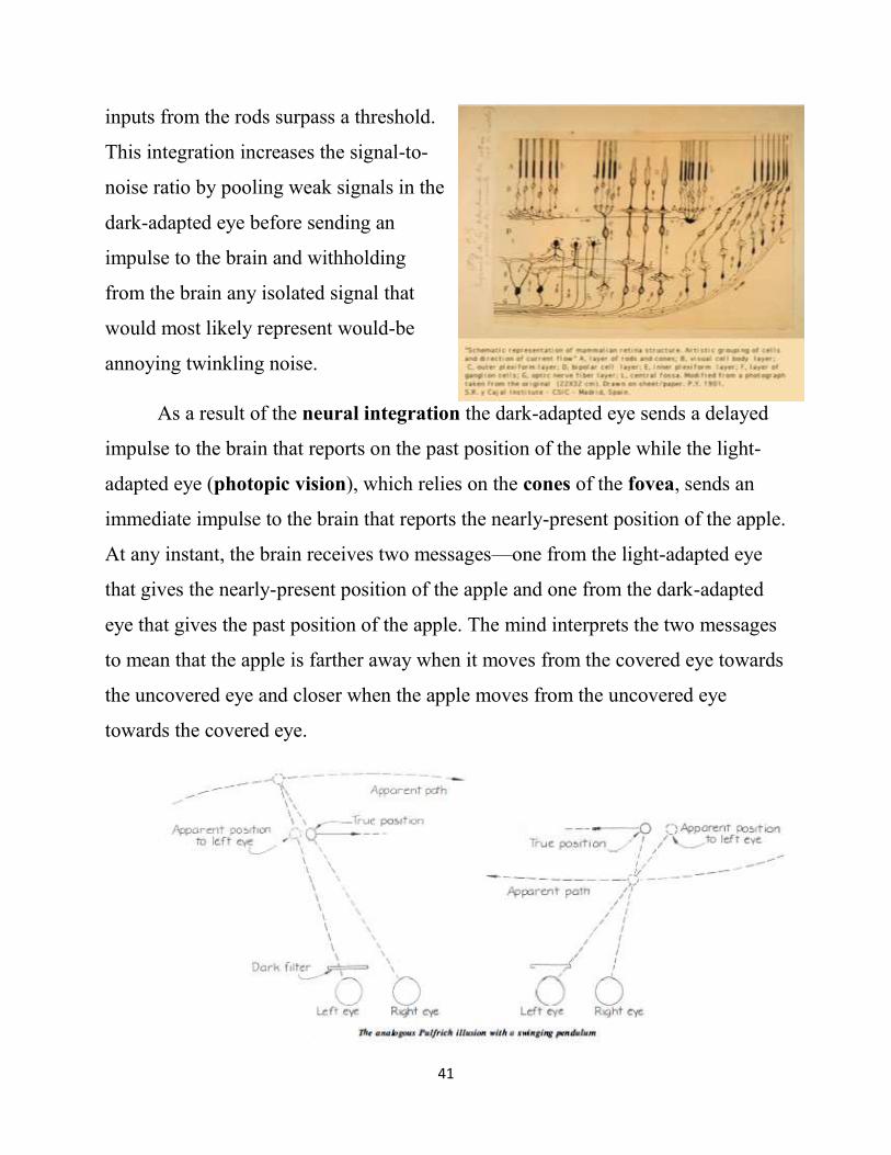
As a result of the neural integration the dark-adapted eye sends a delayed
impulse to the brain that reports on the past position of the apple while the light-
adapted eye (photopic vision), which relies on the cones of the fovea, sends an
immediate impulse to the brain that reports the nearly-present position of the apple.
At any instant, the brain receives two messages—one from the light-adapted eye
that gives the nearly-present position of the apple and one from the dark-adapted
eye that gives the past position of the apple. The mind interprets the two messages
to mean that the apple is farther away when it moves from the covered eye towards
the uncovered eye and closer when the apple moves from the uncovered eye
towards the covered eye.
42
The Pulfrich pendulum effect is not necessarily a maladaptation or a design
flaw, but a happy consequence of the adaptive and well-designed ability of the
neural cells to “rule” over the rods they are connected to in order to minimize
distracting twinkling. This rule increases the signal-to-noise level in dim light by
performing an integration, which is similar to freshman-level calculus. Perhaps it
is possible, as Richard Dawkins (1987) wrote in “The Blind Watchmaker,” “to
understand [a complex process such as vision] in terms of simpler parts that we do
already understand.” Taking his hierarchical reductionism to the limit, Dawkins
believes that complex objects and processes will be “ultimately explained in terms
of the smallest of fundamental particles.”
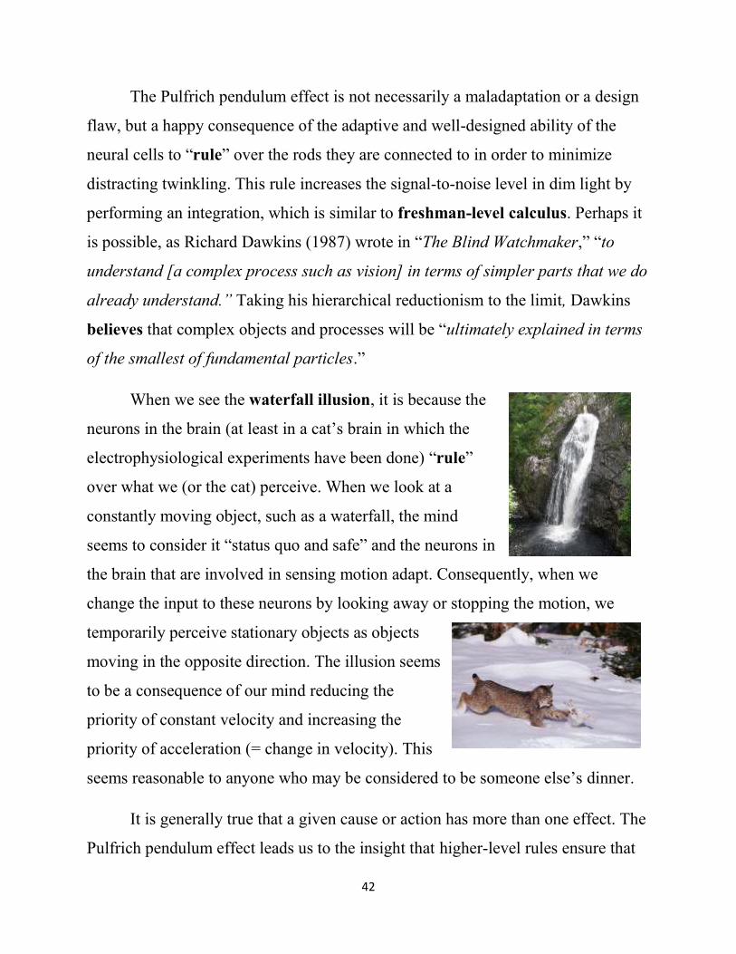
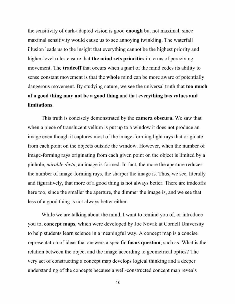
When we see the waterfall illusion, it is because the
neurons in the brain (at least in a cat’s brain in which the
electrophysiological experiments have been done) “rule”
over what we (or the cat) perceive. When we look at a
constantly moving object, such as a waterfall, the mind
seems to consider it “status quo and safe” and the neurons in
the brain that are involved in sensing motion adapt. Consequently, when we
change the input to these neurons by looking away or stopping the motion, we
temporarily perceive stationary objects as objects
moving in the opposite direction. The illusion seems
to be a consequence of our mind reducing the
priority of constant velocity and increasing the
priority of acceleration (= change in velocity). This
seems reasonable to anyone who may be considered to be someone else’s dinner.
It is generally true that a given cause or action has more than one effect. The
Pulfrich pendulum effect leads us to the insight that higher-level rules ensure that
43
the sensitivity of dark-adapted vision is good enough but not maximal, since
maximal sensitivity would cause us to see annoying twinkling. The waterfall
illusion leads us to the insight that everything cannot be the highest priority and
higher-level rules ensure that the mind sets priorities in terms of perceiving
movement. The tradeoff that occurs when a part of the mind cedes its ability to
sense constant movement is that the whole mind can be more aware of potentially
dangerous movement. By studying nature, we see the universal truth that too much
of a good thing may not be a good thing and that everything has values and
limitations.
This truth is concisely demonstrated by the camera obscura. We saw that
when a piece of translucent vellum is put up to a window it does not produce an
image even though it captures most of the image-forming light rays that originate
from each point on the objects outside the window. However, when the number of
image-forming rays originating from each given point on the object is limited by a
pinhole, mirable dictu, an image is formed. In fact, the more the aperture reduces
the number of image-forming rays, the sharper the image is. Thus, we see, literally
and figuratively, that more of a good thing is not always better. There are tradeoffs
here too, since the smaller the aperture, the dimmer the image is, and we see that
less of a good thing is not always better either.
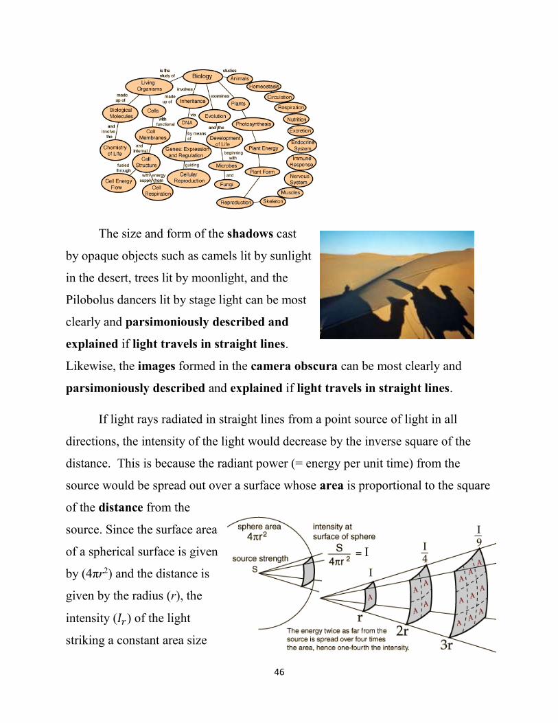
While we are talking about the mind, I want to remind you of, or introduce
you to, concept maps, which were developed by Joe Novak at Cornell University
to help students learn science in a meaningful way. A concept map is a concise
representation of ideas that answers a specific focus question, such as: What is the
relation between the object and the image according to geometrical optics? The
very act of constructing a concept map develops logical thinking and a deeper
understanding of the concepts because a well-constructed concept map reveals

44
hierarchical connections between concepts and tests your understanding of how the
parts relate to the whole. Cmap Tools is software that can facilitate your use of
concept maps and is available to you at no cost at http://cmap.ihmc.us/. Here is a
concept map that I just drew for the focus question: What is the relation between
the object and the image according to geometrical optics?
Concept maps are created by first choosing a provisional focus question,
which is to be answered by the concept map. It is often the case that the focus
question gets revised as you construct the concept map as a result of your
understanding becoming more refined. The second step in forming a concept map
is to think of the concepts that are related to the focus question. Then you do triage
on the list to glean the most important concepts. In the above case, important
concepts included object, image, law of reflection, mirror, law of refraction, lens,
real, virtual, inverted, erect, magnified, minified, the object position (so) and the
focal length (f). The third step is to choose explicit linking words that make
meaningful connections, known as propositions, between the concepts. As you
develop the propositions in the map, you create a hierarchy, through trial and
error, that most clearly and completely answer your focus question.

45
Notice that this concept map does not even mention the eye or the mind.
You can create a different concept map that relates the object to the image on the
retina by including concepts such as cornea, aqueous humor, pupil, iris, crystalline
lens, vitreous humor, and retina. You can also create a concept map that relates the
object to the image perceived by the mind’s eye. Cmap Tools will allow you to
link related concept maps. It will also allow you to build concept maps with other
students in the class. Cmap Tools allows you to attach pictures to the concept,
which is a great way of using the photographs that you take for your calendar to
help you study.
The HyperPhysics website, (http://hyperphysics.phy-
astr.gsu.edu/hbase/hframe.html) makes use of concept maps to explain many
concepts in physics, including concepts related to light and vision
(http://hyperphysics.phy-astr.gsu.edu/hbase/hframe.html).
The HyperPhysics website also includes biology concepts
(http://hyperphysics.phy-astr.gsu.edu/hbase/hframe.html):
46
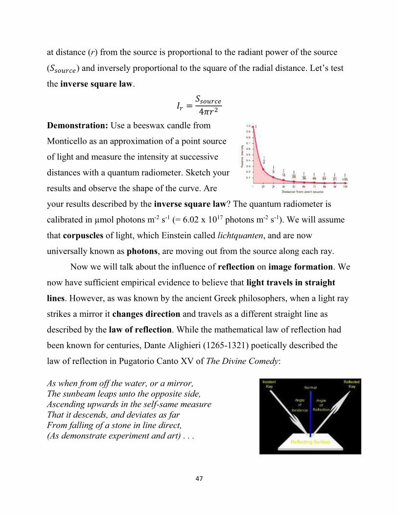
The size and form of the shadows cast
by opaque objects such as camels lit by sunlight
in the desert, trees lit by moonlight, and the
Pilobolus dancers lit by stage light can be most
clearly and parsimoniously described and
explained if light travels in straight lines.
Likewise, the images formed in the camera obscura can be most clearly and
parsimoniously described and explained if light travels in straight lines.
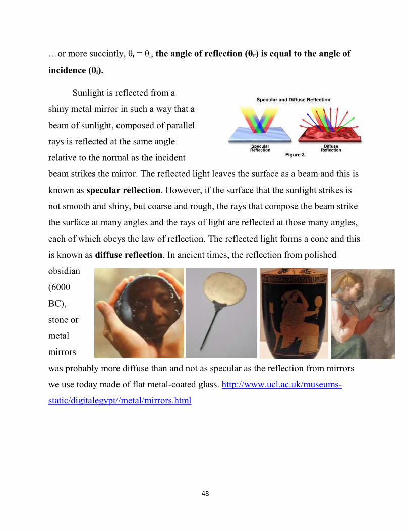
If light rays radiated in straight lines from a point source of light in all
directions, the intensity of the light would decrease by the inverse square of the
distance. This is because the radiant power (= energy per unit time) from the
source would be spread out over a surface whose area is proportional to the square
of the distance from the
source. Since the surface area
of a spherical surface is given
by (4πr2) and the distance is
given by the radius (r), the
intensity (𝐼𝑟) of the light
striking a constant area size
47
at distance (r) from the source is proportional to the radiant power of the source
(𝑆𝑠𝑜𝑢𝑟𝑐𝑒) and inversely proportional to the square of the radial distance. Let’s test
the inverse square law.
𝐼𝑟 =𝑆𝑠𝑜𝑢𝑟𝑐𝑒
4𝜋𝑟2
Demonstration: Use a beeswax candle from
Monticello as an approximation of a point source
of light and measure the intensity at successive
distances with a quantum radiometer. Sketch your
results and observe the shape of the curve. Are
your results described by the inverse square law? The quantum radiometer is
calibrated in µmol photons m-2 s-1 (= 6.02 x 10¹⁷ photons m-2 s-1). We will assume
that corpuscles of light, which Einstein called lichtquanten, and are now
universally known as photons, are moving out from the source along each ray.
Now we will talk about the influence of reflection on image formation. We
now have sufficient empirical evidence to believe that light travels in straight
lines. However, as was known by the ancient Greek philosophers, when a light ray
strikes a mirror it changes direction and travels as a different straight line as
described by the law of reflection. While the mathematical law of reflection had
been known for centuries, Dante Alighieri (1265-1321) poetically described the
law of reflection in Pugatorio Canto XV of The Divine Comedy:
As when from off the water, or a mirror,
The sunbeam leaps unto the opposite side,
Ascending upwards in the self-same measure
That it descends, and deviates as far
From falling of a stone in line direct,
(As demonstrate experiment and art) . . .
48
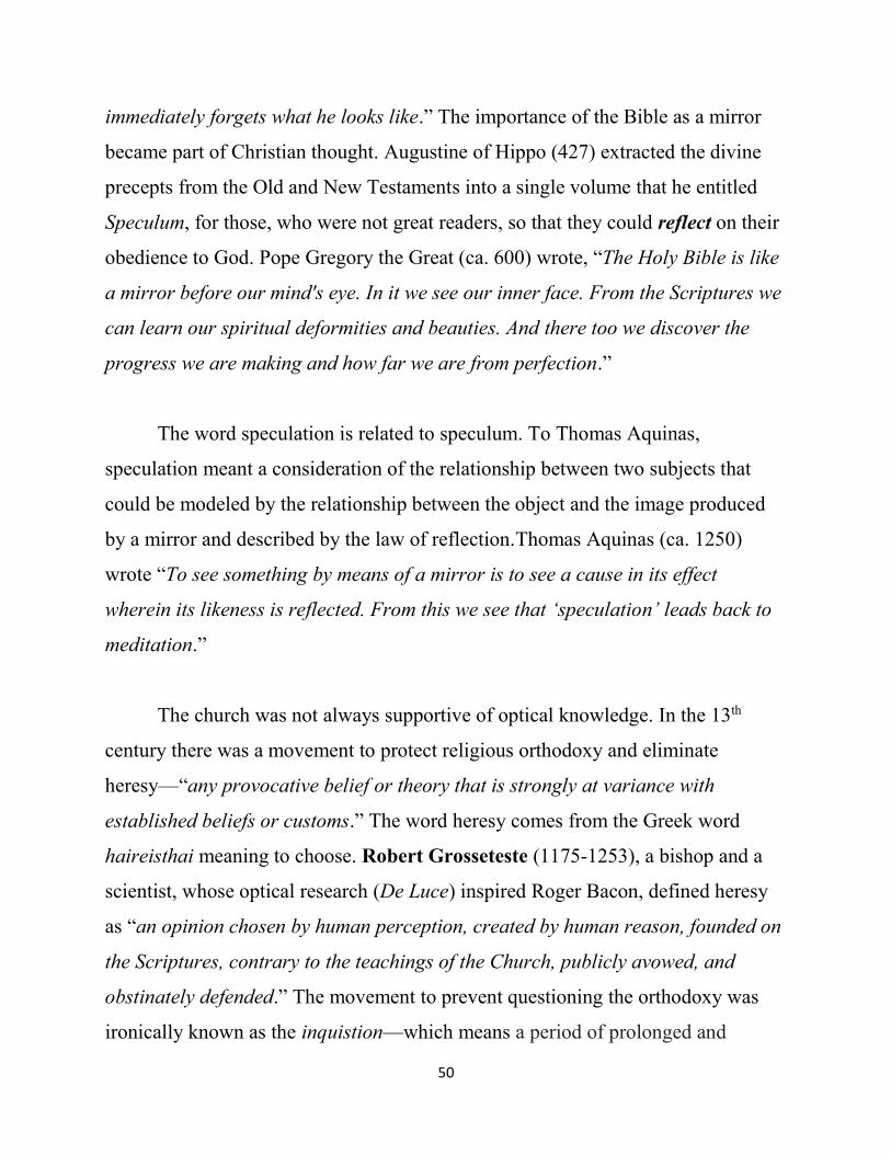
…or more succintly, θr = θi, the angle of reflection (θr) is equal to the angle of
incidence (θi).
Sunlight is reflected from a
shiny metal mirror in such a way that a
beam of sunlight, composed of parallel
rays is reflected at the same angle
relative to the normal as the incident
beam strikes the mirror. The reflected light leaves the surface as a beam and this is
known as specular reflection. However, if the surface that the sunlight strikes is
not smooth and shiny, but coarse and rough, the rays that compose the beam strike
the surface at many angles and the rays of light are reflected at those many angles,
each of which obeys the law of reflection. The reflected light forms a cone and this
is known as diffuse reflection. In ancient times, the reflection from polished
obsidian
(6000
BC),
stone or
metal
mirrors
was probably more diffuse than and not as specular as the reflection from mirrors
we use today made of flat metal-coated glass. http://www.ucl.ac.uk/museums-
static/digitalegypt//metal/mirrors.html

49
Primitive blown glass mirrors coated with metal
were developed in Sidon in 1 AD. Since blown glass is
not as flat as plate glass, these mirrors were small and not
very plane. Metal-coated glass mirrors improved. In his
encyclopedic book, written in the 13th century entitled,
Speculum Majus (which is Latin for Large Mirror) that
“contains that [which] is worth admiring or imitating among
the things that have been done or said, in the world visible and
invisible,” Vincent of Beauvais (1190-1264) extolled the
virtues of tin-coated glass mirrors over polished metal mirrors.
By the 16th century, reflective and flat mercury-coated plate
glass mirrors were produced by Venetian glassmakers. The
secret process used to make the excellent mirrors became
known throughout Europe as a result of industrial espionage.
The toxic mercury was finally replaced with silver, tin and/or aluminum.
At the time the New Testament was written, the images produced by mirrors
(specula in Latin) were probably not very sharp. Moreover, the mirrors were
probably made of metal and not glass. Consequently, “For now we see only a
reflection as in a mirror” was probably anachronistically translated in the 17th
century as “For now we see through a glass, darkly (Videmus nunc per speculum
in aenigmate)” (1 Corinthians 13:12).
As Roger Bacon (1214-1292) realized, the Bible makes use of many optical
analogies involving reflections. It is written in Proverbs (27:19), “As water reflects
the face, so one’s life reflects the heart.” The apostle James (James 1:23-24) wrote,
“Anyone who listens to the word but does not do what it says is like someone who
looks at his face in a mirror and, after looking at himself, goes away and
50
immediately forgets what he looks like.” The importance of the Bible as a mirror
became part of Christian thought. Augustine of Hippo (427) extracted the divine
precepts from the Old and New Testaments into a single volume that he entitled
Speculum, for those, who were not great readers, so that they could reflect on their
obedience to God. Pope Gregory the Great (ca. 600) wrote, “The Holy Bible is like
a mirror before our mind's eye. In it we see our inner face. From the Scriptures we
can learn our spiritual deformities and beauties. And there too we discover the
progress we are making and how far we are from perfection.”
The word speculation is related to speculum. To Thomas Aquinas,
speculation meant a consideration of the relationship between two subjects that
could be modeled by the relationship between the object and the image produced
by a mirror and described by the law of reflection.Thomas Aquinas (ca. 1250)
wrote “To see something by means of a mirror is to see a cause in its effect
wherein its likeness is reflected. From this we see that ‘speculation’ leads back to
meditation.”
The church was not always supportive of optical knowledge. In the 13th
century there was a movement to protect religious orthodoxy and eliminate
heresy—“any provocative belief or theory that is strongly at variance with
established beliefs or customs.” The word heresy comes from the Greek word
haireisthai meaning to choose. Robert Grosseteste (1175-1253), a bishop and a
scientist, whose optical research (De Luce) inspired Roger Bacon, defined heresy
as “an opinion chosen by human perception, created by human reason, founded on
the Scriptures, contrary to the teachings of the Church, publicly avowed, and
obstinately defended.” The movement to prevent questioning the orthodoxy was
ironically known as the inquistion—which means a period of prolonged and
51
intensive questioning (inquisitio is Latin
for inquiry). During the inquisition, one
of the questions in the Summa de officio
inquisitionis of 1270 was aimed at
finding those who practiced divination
using reflective objects
(catoptromancy), “Have you conducted
experiments with mirrors, swords, fingernails, spheres or ivory handles?”
The mirror was a very powerful symbol—being capable of
reflecting the truth and of producing illusions. The German folk legend
of Till Eulenspiegel (eulen and spiegel are the German words for owl
and mirror, respectively) describes a trickster born around 1300 who
carried a mirror and an owl as he traveled through the countryside
exposing injustice, lunacy and hypocrisy. Richard Strauss put Till
Eulenspiegel’s story to music. In the beginning of Til Eulenspiegel’s
Merry Pranks, the music tells of his trips through the countryside poking fun at and
mocking the establishment. The end tells us of his capture by the authorities, his
death sentence for blasphemy, and his execution by hanging. After his death, the
playful initial musical theme reappears, suggesting that Till Eulenspiegel’s
message will live forever. https://www.youtube.com/watch?v=S7O9Oa22nsQ
Even today, various mirrors tell us about ourselves
and the world around us. In analogy to silvered glass
mirrors, we ask, do these newspapers and magazines
reflect the truth or produce illusion?

52
We can determine the position, orientation, and size of an image formed by a
plane mirror by drawing light rays radiating from at least
two different points on the object to the mirror. Then we
assume that rays that strike the mirror are reflected in such a
way that the angle of reflection equals the angle of incidence.
Practically, we find a given image point by drawing two of
the infinite number of rays that radiate from a given point on the object. We draw
these rays, which are known as characteristic rays, using the following rules:
1. From a given point on the object, draw a line perpendicular to the mirror.
Because θi = 0 then θr = 0. Draw the reflected ray and then extend the reflected ray
backwards behind the mirror.
2. From the same point on the object, draw another
line to any other point on the mirror. Draw the
normal to the mirror at this point and then draw the
reflected ray using the rule θr = θi. Extend the
reflected rays backwards behind the mirror, to the
other extended reflected ray originating from the
same point on the object. The point of intersection
of the extensions of the reflected rays originating
from the same object point is the position of the
image of that object point. If the reflected rays converged in front of the mirror,
which they do not do when they strike a plane mirror, a real image would have
been formed. A real image is an image that can be projected on a piece of
translucent vellum. A real image is composed of radiant energy, and the light
intensities of the points that make up a real image can be measured with a light
53
meter. However, since the reflected rays diverge from a plane mirror, we extend
the rays backwards from where they appear to be diverging. While an image
appears in the place from which the rays appear to diverge, a piece of translucent
vellum would not display an image. The image is virtual—it appears only in our
mind’s eye.
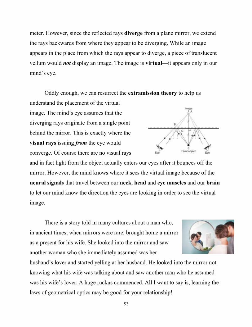
Oddly enough, we can resurrect the extramission theory to help us
understand the placement of the virtual
image. The mind’s eye assumes that the
diverging rays originate from a single point
behind the mirror. This is exactly where the
visual rays issuing from the eye would
converge. Of course there are no visual rays
and in fact light from the object actually enters our eyes after it bounces off the
mirror. However, the mind knows where it sees the virtual image because of the
neural signals that travel between our neck, head and eye muscles and our brain
to let our mind know the direction the eyes are looking in order to see the virtual
image.
There is a story told in many cultures about a man who,
in ancient times, when mirrors were rare, brought home a mirror
as a present for his wife. She looked into the mirror and saw
another woman who she immediately assumed was her
husband’s lover and started yelling at her husband. He looked into the mirror not
knowing what his wife was talking about and saw another man who he assumed
was his wife’s lover. A huge ruckus commenced. All I want to say is, learning the
laws of geometrical optics may be good for your relationship!
54
Not all mirrors are planar. We will look at images produced by concave and
convex mirrors.
Demonstration: Place a short candle 40-50 cm
from the convex mirror and slowly move it
toward the mirror and away from you. Describe
what happens to the image of the candle as its
distance to the convex mirror decreases. Place the
candle 40-50 cm from the concave mirror and
slowly move it toward the mirror and away from you. Describe what happens to
the image of the candle as its distance to the concave mirror decreases. Compare
the images made by the concave and the convex mirrors. Place the candle
approximately 30 cm from the concave mirror. Find the image with the translucent
vellum. Move the candle towards the mirror. Find the image with the translucent
vellum. Move the candle away from the mirror. Find the image with the translucent
vellum. How does the image formed by the concave mirror on the translucent
vellum change with the position of the object?
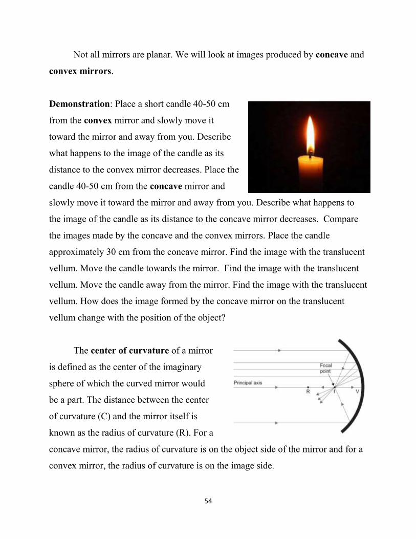
The center of curvature of a mirror
is defined as the center of the imaginary
sphere of which the curved mirror would
be a part. The distance between the center
of curvature (C) and the mirror itself is
known as the radius of curvature (R). For a
concave mirror, the radius of curvature is on the object side of the mirror and for a
convex mirror, the radius of curvature is on the image side.
55
The line connecting the midpoint of the mirror with the center of curvature is
called the principal axis of the mirror. The vertex V represents the intersection of
the mirror and the principal axis. The focus, which is positive for a concave
mirror, is on the principal axis midway between the mirror and the center of
curvature. The focal length of a mirror is the distance between the focus and the
vertex.
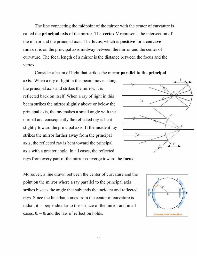
Consider a beam of light that strikes the mirror parallel to the principal
axis. When a ray of light in this beam moves along
the principal axis and strikes the mirror, it is
reflected back on itself. When a ray of light in this
beam strikes the mirror slightly above or below the
principal axis, the ray makes a small angle with the
normal and consequently the reflected ray is bent
slightly toward the principal axis. If the incident ray
strikes the mirror farther away from the principal
axis, the reflected ray is bent toward the principal
axis with a greater angle. In all cases, the reflected
rays from every part of the mirror converge toward the focus.
Moreover, a line drawn between the center of curvature and the
point on the mirror where a ray parallel to the principal axis
strikes bisects the angle that subtends the incident and reflected
rays. Since the line that comes from the center of curvature is
radial, it is perpendicular to the surface of the mirror and in all
cases, θr = θi and the law of reflection holds.
56
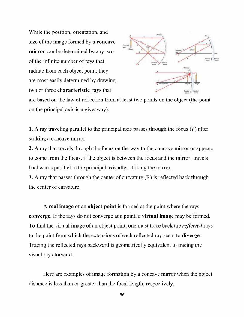
While the position, orientation, and
size of the image formed by a concave
mirror can be determined by any two
of the infinite number of rays that
radiate from each object point, they
are most easily determined by drawing
two or three characteristic rays that
are based on the law of reflection from at least two points on the object (the point
on the principal axis is a giveaway):
1. A ray traveling parallel to the principal axis passes through the focus (𝑓) after
striking a concave mirror.
2. A ray that travels through the focus on the way to the concave mirror or appears
to come from the focus, if the object is between the focus and the mirror, travels
backwards parallel to the principal axis after striking the mirror.
3. A ray that passes through the center of curvature (R) is reflected back through
the center of curvature.
A real image of an object point is formed at the point where the rays
converge. If the rays do not converge at a point, a virtual image may be formed.
To find the virtual image of an object point, one must trace back the reflected rays
to the point from which the extensions of each reflected ray seem to diverge.
Tracing the reflected rays backward is geometrically equivalent to tracing the
visual rays forward.
Here are examples of image formation by a concave mirror when the object
distance is less than or greater than the focal length, respectively.

57
Convex mirrors, by convention, have a positive radius of curvature. When
a beam of light parallel to the principal axis strikes a convex mirror, the rays are
reflected away from the principal axis, and therefore diverge. If we follow the
reflected rays backward, they appear to originate
from a point behind the mirror, known as the
focus. Since the focus is behind the mirror, 𝒇 and
the focal length are negative. We can draw a
line between the center of curvature and the
point on the mirror where a ray parallel to the
principal axis strikes. This line, which is perpendicular to the surface of the mirror,
bisects the angle that subtends the incident and reflected rays so that in all cases, θr
= θi and the law of reflection holds.
58
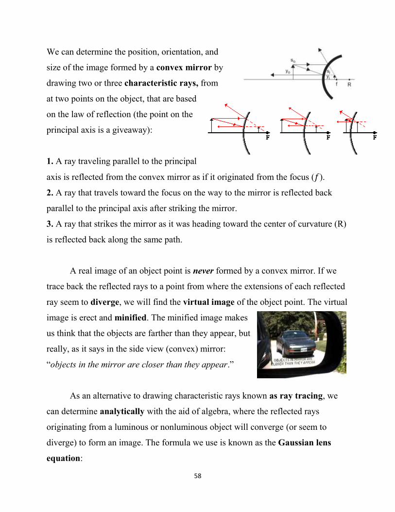
We can determine the position, orientation, and
size of the image formed by a convex mirror by
drawing two or three characteristic rays, from
at two points on the object, that are based
on the law of reflection (the point on the
principal axis is a giveaway):
1. A ray traveling parallel to the principal
axis is reflected from the convex mirror as if it originated from the focus (𝑓).
2. A ray that travels toward the focus on the way to the mirror is reflected back
parallel to the principal axis after striking the mirror.
3. A ray that strikes the mirror as it was heading toward the center of curvature (R)
is reflected back along the same path.
A real image of an object point is never formed by a convex mirror. If we
trace back the reflected rays to a point from where the extensions of each reflected
ray seem to diverge, we will find the virtual image of the object point. The virtual
image is erect and minified. The minified image makes
us think that the objects are farther than they appear, but
really, as it says in the side view (convex) mirror:
“objects in the mirror are closer than they appear.”
As an alternative to drawing characteristic rays known as ray tracing, we
can determine analytically with the aid of algebra, where the reflected rays
originating from a luminous or nonluminous object will converge (or seem to
diverge) to form an image. The formula we use is known as the Gaussian lens
equation:
59
1
𝑠𝑜+
1
𝑠𝑖=
1
𝑓
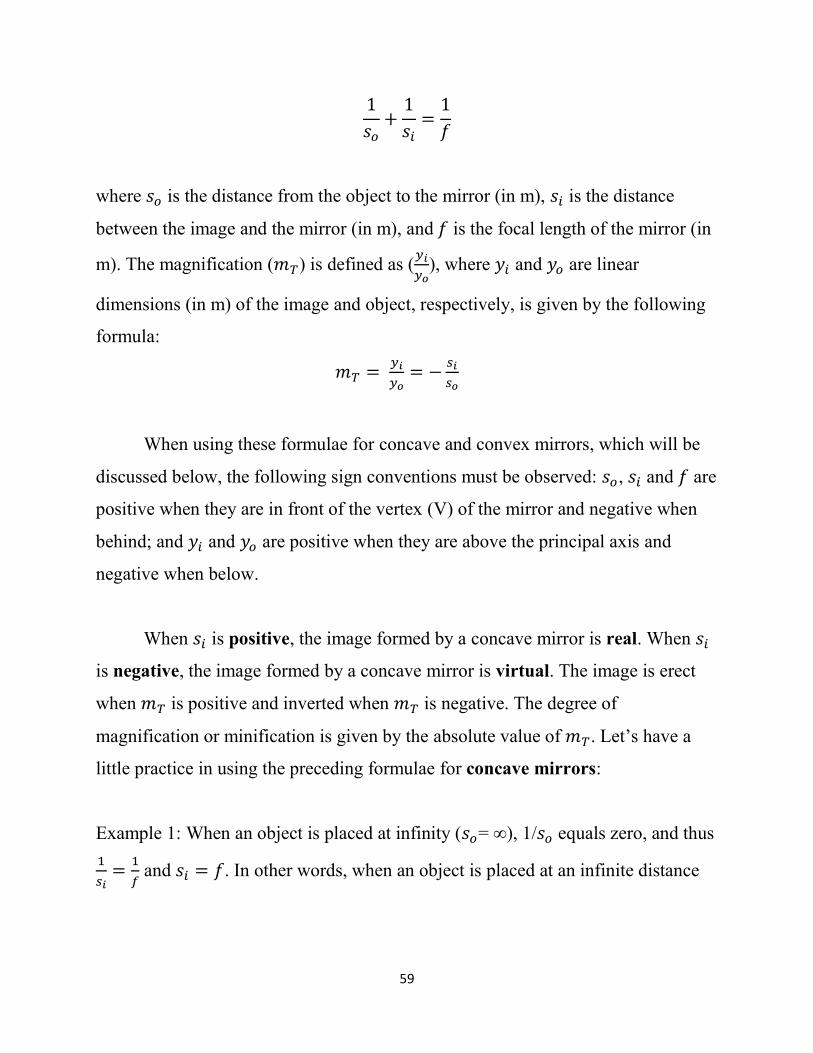
where 𝑠𝑜 is the distance from the object to the mirror (in m), 𝑠𝑖 is the distance
between the image and the mirror (in m), and 𝑓 is the focal length of the mirror (in
m). The magnification (𝑚𝑇) is defined as (𝑦𝑖
𝑦𝑜), where 𝑦𝑖 and 𝑦𝑜 are linear
dimensions (in m) of the image and object, respectively, is given by the following
formula:
𝑚𝑇 = 𝑦𝑖
𝑦𝑜= −
𝑠𝑖
𝑠𝑜
When using these formulae for concave and convex mirrors, which will be
discussed below, the following sign conventions must be observed: 𝑠𝑜, 𝑠𝑖 and 𝑓 are
positive when they are in front of the vertex (V) of the mirror and negative when
behind; and 𝑦𝑖 and 𝑦𝑜 are positive when they are above the principal axis and
negative when below.
When 𝑠𝑖 is positive, the image formed by a concave mirror is real. When 𝑠𝑖
is negative, the image formed by a concave mirror is virtual. The image is erect
when 𝑚𝑇 is positive and inverted when 𝑚𝑇 is negative. The degree of
magnification or minification is given by the absolute value of 𝑚𝑇. Let’s have a
little practice in using the preceding formulae for concave mirrors:
Example 1: When an object is placed at infinity (𝑠𝑜= ∞), 1/𝑠𝑜 equals zero, and thus
1
𝑠𝑖=
1
𝑓 and 𝑠𝑖 = 𝑓. In other words, when an object is placed at an infinite distance
60
from the mirror, the image is formed at the focal point and the magnification (−𝑠𝑖
𝑠𝑜)
is equal to zero.
Example 2: When an object is placed at the focus (𝑠𝑜= 𝑓), 1
𝑓+
1
𝑠𝑖=
1
𝑓. Thus
1
𝑠𝑖 must
equal zero and 𝑠𝑖 must be equal to infinity. In other words, when an object is
placed at the focus, the image is formed at infinity, and the magnification (−𝑠𝑖
𝑠𝑜) is
almost infinite.
Example 3: When an object is placed at the center of curvature (𝑠𝑜= 2𝑓), then 1
2𝑓+
1
𝑠𝑖=
1
𝑓 and
1
𝑠𝑖=
1
2𝑓 (remember ½ - ¼ = ¼). Thus 𝑠𝑖 = 2𝑓, and the image is real
and the same distance from the mirror as the object is. The magnification (−𝑠𝑖
𝑠𝑜) is
minus one, and the image is inverted.
Example 4: When an object is placed at a distance equal to 1
2𝑓, which is between
the focus and the mirror, then 2
𝑓+
1
𝑠𝑖=
1
𝑓. Thus
1
𝑠𝑖=
1
𝑓−
2
𝑓 and
1
𝑠𝑖= −
1
𝑓, and 𝑠𝑖 =
−𝑓. Since 𝑠𝑖is a negative number, the image is behind the mirror and virtual.
Since −𝑠𝑖
𝑠𝑜 equals +2, the image is erect and twice the height as the object.
The Gaussian lens equation can also be used to determine the nature of
images produced by convex mirrors. For convex mirrors, the focal length is
negative. To form any image in a convex mirror where 𝑓is always negative, 𝑠𝑜
must be positive. According to the Gaussian lens equation, 1
𝑠𝑜+
1
𝑠𝑖=
1
𝑓, 𝑠𝑖 will
always be negative and the image will always be behind the mirror and virtual.
Since −𝑠𝑖
𝑠𝑜 will always be positive, the image will always be erect.
61
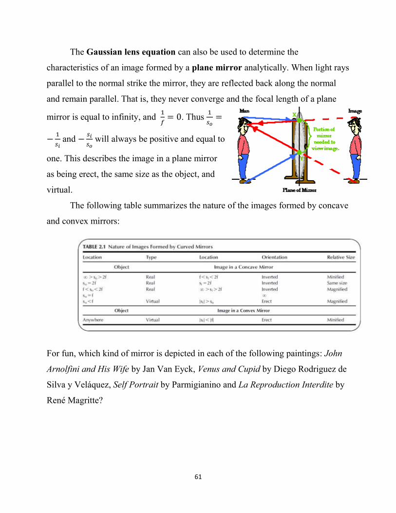
The Gaussian lens equation can also be used to determine the
characteristics of an image formed by a plane mirror analytically. When light rays
parallel to the normal strike the mirror, they are reflected back along the normal
and remain parallel. That is, they never converge and the focal length of a plane
mirror is equal to infinity, and 1
𝑓= 0. Thus
1
𝑠𝑜=
−1
𝑠𝑖 and −
𝑠𝑖
𝑠𝑜 will always be positive and equal to
one. This describes the image in a plane mirror
as being erect, the same size as the object, and
virtual.
The following table summarizes the nature of the images formed by concave
and convex mirrors:
For fun, which kind of mirror is depicted in each of the following paintings: John
Arnolfini and His Wife by Jan Van Eyck, Venus and Cupid by Diego Rodriguez de
Silva y Veláquez, Self Portrait by Parmigianino and La Reproduction Interdite by
René Magritte?

62
John Ashbery (1974) wrote a poem Self-portrait in a convex
(http://www.poetryfoundation.org/poetrymagazine/browse/124/5#!/20596528/0
https://www.youtube.com/watch?v=zrvXX9QVAT8). Other paintings that depict
mirrors include, Vanity by Hans Memling; The Moneychanger and his Wife by
Quentin Metsys; The Bar at the Folies Bergères by Edouard Manet; Joking Couple
by Hans von Aachen; Venus in Front of the Mirror by Peter Paul Rubens; Venus in
Front of the Mirror by Titian; Nude Standing before a Mirror by Henri Toulouse
Lautrec; and Triple Self Portrait by Norman Rockwell. See
http://larsdatter.com/mirrors.htm.
The set in Christopher Wheeldon's Scènes de Ballet
is a Russian ballet studio bisected by a barre and an
imaginary mirror. Sixty two dancers are divided
between “real” dancers and their “reflections.”
How many “real” dancers are in this freestyle dance
video called Mirror Story?
https://www.youtube.com/watch?v=HzZ1K-IRxA4
63
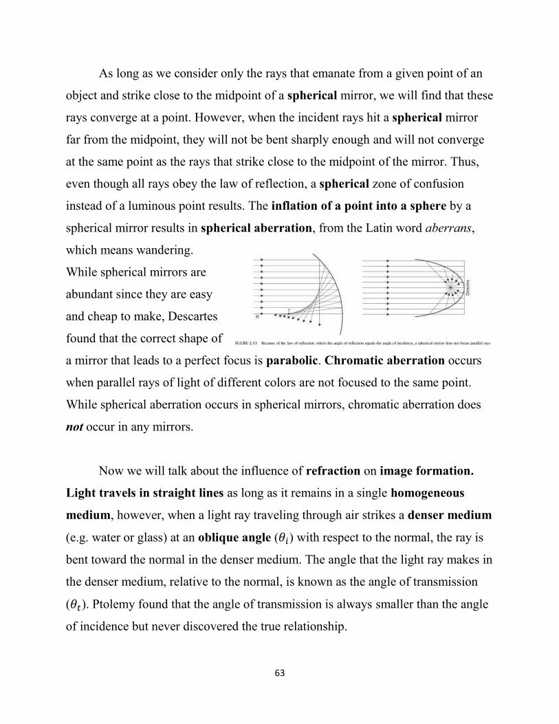
As long as we consider only the rays that emanate from a given point of an
object and strike close to the midpoint of a spherical mirror, we will find that these
rays converge at a point. However, when the incident rays hit a spherical mirror
far from the midpoint, they will not be bent sharply enough and will not converge
at the same point as the rays that strike close to the midpoint of the mirror. Thus,
even though all rays obey the law of reflection, a spherical zone of confusion
instead of a luminous point results. The inflation of a point into a sphere by a
spherical mirror results in spherical aberration, from the Latin word aberrans,
which means wandering.
While spherical mirrors are
abundant since they are easy
and cheap to make, Descartes
found that the correct shape of
a mirror that leads to a perfect focus is parabolic. Chromatic aberration occurs
when parallel rays of light of different colors are not focused to the same point.
While spherical aberration occurs in spherical mirrors, chromatic aberration does
not occur in any mirrors.
Now we will talk about the influence of refraction on image formation.
Light travels in straight lines as long as it remains in a single homogeneous
medium, however, when a light ray traveling through air strikes a denser medium
(e.g. water or glass) at an oblique angle (𝜃𝑖) with respect to the normal, the ray is
bent toward the normal in the denser medium. The angle that the light ray makes in
the denser medium, relative to the normal, is known as the angle of transmission
(𝜃𝑡). Ptolemy found that the angle of transmission is always smaller than the angle
of incidence but never discovered the true relationship.
64
The true mathematical relationship between the angle of incidence and the
angle of transmission was first worked out by Willebrord Snel van Royen in 1621.
Snel, also known as Snellius did not publish his work. René Descartes, who
independently worked out the relationship, published the relationship in 1637. The
law of refraction, which is known as the Snel-Descartes Law, states that when
light passes from air to a denser medium, the ratio of the sine of the angle of
incidence to the sine of the angle of transmission equal to a constant, called the
refractive index. The Snel-Descartes Law can be expressed by the following
equation:
sin 𝜃𝑖
sin 𝜃𝑡 =
𝑛𝑡
𝑛𝑖 = 𝑛𝑡 (when 𝑛𝑖 = 1)
where 𝑛𝑡 is the refractive index of the denser medium and 𝑛𝑖 is the refractive index
of air (𝑛𝑖 = 1). The Snel-Descartes Law can be written more generally as:
𝑛𝑖 sin 𝜃𝑖 = 𝑛𝑡 sin 𝜃𝑡
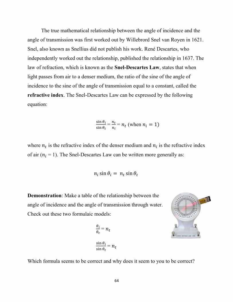
Demonstration: Make a table of the relationship between the
angle of incidence and the angle of transmission through water.
Check out these two formulaic models:
𝜃𝑖
𝜃𝑡 = 𝑛𝑡
sin 𝜃𝑖
sin 𝜃𝑡 = 𝑛𝑡
Which formula seems to be correct and why does it seem to you to be correct?

65
Demonstration: In general, the denser a transparent
medium, the greater is its refractive index. We can observe
this by measuring the refractive indices of 0%, 5% and 10%
(w/v) sucrose solutions with a hand-held refractometer. The
solution in the hand-held refractometer bends light in a
manner that depends on the refractive index of the solution.
The hand-held refractometer is useful to beer and wine makers and is often
calibrated in degrees Brix instead of refractive index. Degrees Brix is equivalent to
the percent sugar (S). The refractive index of the solution = 1.3333 + (0.0018)(S).
Demonstration: A piece of Pyrex glass becomes invisible
when it is placed in a solution of Wesson (soybean) oil, but
not in air or water. Can you guess why?
When a light ray passes from air through a piece of glass with parallel
edges and returns to the air, the
refraction at the far edge reverses
the refraction at the near edge and
the ray emerges parallel to the
incident ray, although slightly
displaced. The amount of
displacement depends on two things: the refractive index of the glass and the
distance the beam travels in the glass.
66
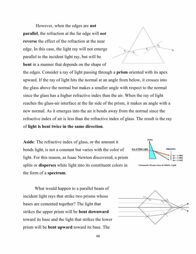
However, when the edges are not
parallel, the refraction at the far edge will not
reverse the effect of the refraction at the near
edge. In this case, the light ray will not emerge
parallel to the incident light ray, but will be
bent in a manner that depends on the shape of
the edges. Consider a ray of light passing through a prism oriented with its apex
upward. If the ray of light hits the normal at an angle from below, it crosses into
the glass above the normal but makes a smaller angle with respect to the normal
since the glass has a higher refractive index than the air. When the ray of light
reaches the glass-air interface at the far side of the prism, it makes an angle with a
new normal. As it emerges into the air it bends away from the normal since the
refractive index of air is less than the refractive index of glass. The result is the ray
of light is bent twice in the same direction.
Aside: The refractive index of glass, or the amount it
bends light, is not a constant but varies with the color of
light. For this reason, as Isaac Newton discovered, a prism
splits or disperses white light into its constituent colors in
the form of a spectrum.
What would happen to a parallel beam of
incident light rays that strike two prisms whose
bases are cemented together? The light that
strikes the upper prism will be bent downward
toward its base and the light that strikes the lower
prism will be bent upward toward its base. The
67
two halves of the beam of light will converge and cross on the other side.
However, the beam emerging from this double prism will not come to a focus since
the rays that strike the two corresponding prisms farther and farther from the
principal axis all strike at the same angles but travel through less and less glass
and thus will converge at greater and greater distances from the double prism. Is
there a particular shape of glass that will bring parallel rays to converge at a focus?
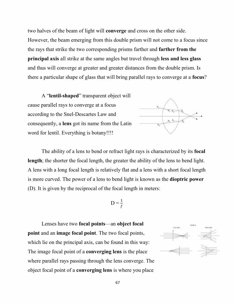
A “lentil-shaped” transparent object will
cause parallel rays to converge at a focus
according to the Snel-Descartes Law and
consequently, a lens got its name from the Latin
word for lentil. Everything is botany!!!!
The ability of a lens to bend or refract light rays is characterized by its focal
length; the shorter the focal length, the greater the ability of the lens to bend light.
A lens with a long focal length is relatively flat and a lens with a short focal length
is more curved. The power of a lens to bend light is known as the dioptric power
(D). It is given by the reciprocal of the focal length in meters:
D = 1
𝑓
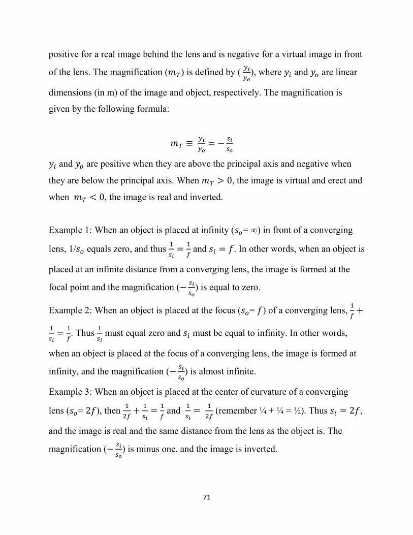
Lenses have two focal points—an object focal
point and an image focal point. The two focal points,
which lie on the principal axis, can be found in this way:
The image focal point of a converging lens is the place
where parallel rays passing through the lens converge. The
object focal point of a converging lens is where you place

68
a point source of light so that the light that passes through the lens comes out as
parallel rays. Converging lenses have positive focal lengths.
The image focal point of a diverging lens is the place where rays diverging
from the lens appear to have diverged from. The object focal point is where a
virtual point source of light seems to be when parallel rays of light emerge from
the lens. Diverging lenses have negative focal lengths.
Demonstration: Place the bayberry candle from Monticello at one end of
the desk. Look at it close-up through the 0.5 m (2 D) and then the
1 m (1 D) focal length double convex converging lenses. Describe
the images formed by the two lenses. Are the images real or
virtual? Erect or inverted? Which one forms the larger image?
Then place the 0.5 m and 1 m focal length converging lenses side
by side about 2 m away from the candle. Find the images behind
the lenses by moving the translucent vellum backwards starting at the back of the
lenses. Describe and compare the images that are formed by the two lenses. Are
the images real or virtual? Erect or inverted? Which one forms the larger image?
Place a -1 m (-1 D) focal length double concave diverging lens immediately behind
the 0.5 m (2 D) double convex converging lens. Find the image with the
translucent vellum. What happens to the image? Compare it to the images formed
by the 0.5 m and the 1m focal length converging lenses.
Bayberry (Myrica pensylvanica) grows on the patio of the Plant
Sciences Bldg. Why might the berries be coated with wax? Why are
plants in general, whether they live in the desert or the tropics, coated
with wax?

69
We can characterize the type, location,
orientation, and relative size of images formed
by converging and diverging lenses using the
ray tracing method just as we characterized the
images formed by mirrors. We must draw two or
three characteristic rays from at least two points that obey the Snel-Descartes
Law Law (a point on the principal axis is a giveaway):
1. A ray that strikes a converging lens parallel to the principal axis goes
through the image focus (𝑓𝑖).
2. A ray that strikes a diverging lens parallel to the principal axis appears to
have come from the image focus (𝑓𝑖).
3. A ray that strikes a converging lens after it passes through the object focus
(𝑓𝑜) emerges parallel to the principal axis.
4. A ray that strikes a diverging lens on its way to the object focus (𝑓𝑜) emerges
parallel to the principal axis.
5. A ray that passes through the vertex (V) of a converging or diverging lens
passes through undeviated.
Draw three characteristic rays from each point on
the object when the object is farther than the object
focal length of a converging lens. The rays converge
and the image is real, magnified and inverted. As the
object moves farther away from the focus, the image
goes from magnified to same size to minified.
Draw three characteristic rays from each point on the object when the object is
closer than the object focal length of a converging lens. Since the rays do not

70
converge, we have to trace them back and see where they appear to diverge from.
The image is erect, virtual and magnified. As the object moves toward the focus,
the magnification increases.
Draw three characteristic rays from each point on the object when the object is
anywhere relative to the image focal point of a diverging lens. Since the rays do
not converge, we have to trace them back and see where they appear to diverge
from. The image is
virtual, erect and
minified. As the object
is moved farther from
the lens, the image will
be more and more
minified.
As an alternative to drawing characteristic rays, we can determine
analytically with the aid of algebra, where the refracted rays originating from a
luminous or nonluminous object will converge to form an image. We use the same
Gaussian lens equation we used for finding the images formed by mirrors:
1
𝑠𝑜+
1
𝑠𝑖=
1
𝑓
where 𝑠𝑜 is the distance from the object to the lens (in m), 𝑠𝑖 is the distance
between the image and the lens (in m), and 𝑓 is the focal length of the lens (in m).
A converging lens has a positive focal length (𝑓) and a diverging lens has a
negative focal length (𝑓). 𝑠𝑜 is positive for a real object in front of the lens. 𝑠𝑖 is
71
positive for a real image behind the lens and is negative for a virtual image in front
of the lens. The magnification (𝑚𝑇) is defined by ( 𝑦𝑖
𝑦𝑜), where 𝑦𝑖 and 𝑦𝑜 are linear
dimensions (in m) of the image and object, respectively. The magnification is
given by the following formula:
𝑚𝑇 ≡ 𝑦𝑖
𝑦𝑜= −
𝑠𝑖
𝑠𝑜
𝑦𝑖 and 𝑦𝑜 are positive when they are above the principal axis and negative when
they are below the principal axis. When 𝑚𝑇 > 0, the image is virtual and erect and
when 𝑚𝑇 < 0, the image is real and inverted.
Example 1: When an object is placed at infinity (𝑠𝑜= ∞) in front of a converging
lens, 1/𝑠𝑜 equals zero, and thus 1
𝑠𝑖=
1
𝑓 and 𝑠𝑖 = 𝑓. In other words, when an object is
placed at an infinite distance from a converging lens, the image is formed at the
focal point and the magnification (−𝑠𝑖
𝑠𝑜) is equal to zero.
Example 2: When an object is placed at the focus (𝑠𝑜= 𝑓) of a converging lens, 1
𝑓+
1
𝑠𝑖=
1
𝑓. Thus
1
𝑠𝑖 must equal zero and 𝑠𝑖 must be equal to infinity. In other words,
when an object is placed at the focus of a converging lens, the image is formed at
infinity, and the magnification (−𝑠𝑖
𝑠𝑜) is almost infinite.
Example 3: When an object is placed at the center of curvature of a converging
lens (𝑠𝑜= 2𝑓), then 1
2𝑓+
1
𝑠𝑖=
1
𝑓 and
1
𝑠𝑖=
1
2𝑓 (remember ¼ + ¼ = ½). Thus 𝑠𝑖 = 2𝑓,
and the image is real and the same distance from the lens as the object is. The
magnification (−𝑠𝑖
𝑠𝑜) is minus one, and the image is inverted.
72
Example 4: When an object is placed at a distance equal to 1
2𝑓 in front of a
converging lens, which is between the focus and the lens, then 2
𝑓+
1
𝑠𝑖=
1
𝑓. Thus
1
𝑠𝑖=
1
𝑓−
2
𝑓 and
1
𝑠𝑖= −
1
𝑓, and 𝑠𝑖 = −𝑓. Since 𝑠𝑖is a negative number, the image is
is on the same side of the lens as the object, and it is virtual. Since −𝑠𝑖
𝑠𝑜 equals +2,
the image is erect and twice the height as the object.
Example 5: When an object is placed at a positive distance equal to −1
2𝑓
(remember that 𝑓 is negative) in front of a diverging lens, which is between the
focus and the lens, then −2
𝑓+
1
𝑠𝑖=
1
𝑓. Thus
1
𝑠𝑖=
1
𝑓−
−2
𝑓 and
1
𝑠𝑖=
3
𝑓, and 𝑠𝑖 =
𝑓
3.
Since 𝑠𝑖 is a negative number, the image is is on the same side of the lens as the
object, and it is virtual. Since −𝑠𝑖
𝑠𝑜 equals +
2
3, the image is erect and two-thirds the
height as the object.
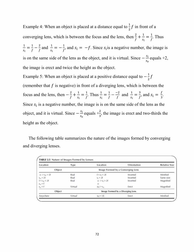
The following table summarizes the nature of the images formed by converging
and diverging lenses.
73
Refracting lenses can have both spherical
and chromatic aberrations. Spherical aberration
occurs because the rays from any given object
point that hit a lens with spherical surfaces far
from the principal axis are refracted too strongly, resulting in the inflation of a
point into a sphere. Spherical aberration can be reduced by molding or grinding the
lens so that it has aspherical surfaces or using only the part of the lens close to the
principal axis. Chromatic aberration occurs
because the refractive index of refracting materials
is color-dependent. This results in the violet-blue
rays being more strongly refracted by glass than
the orange-red rays and the image has colored
halos.
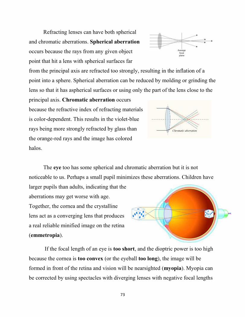
The eye too has some spherical and chromatic aberration but it is not
noticeable to us. Perhaps a small pupil minimizes these aberrations. Children have
larger pupils than adults, indicating that the
aberrations may get worse with age.
Together, the cornea and the crystalline
lens act as a converging lens that produces
a real reliable minified image on the retina
(emmetropia).
If the focal length of an eye is too short, and the dioptric power is too high
because the cornea is too convex (or the eyeball too long), the image will be
formed in front of the retina and vision will be nearsighted (myopia). Myopia can
be corrected by using spectacles with diverging lenses with negative focal lengths

74
and negative dioptric powers. Myopia can also be
corrected with Lasik surgery that makes the cornea less
convex.
If the focal length of an eye is too long, and the
dioptric power is too low because the cornea is not
convex enough (or the eyeball too short), the image
will be formed behind the retina and vision will be
farsighted (hyperopia). Hyperopia can be corrected by
using spectacles with converging lenses with positive
focal lengths and positive dioptric powers. Hyperopia
can also be corrected with Lasik surgery that makes the
cornea rounder.
The effect of spectacles on myopia (nearsightedness) and hyperopia
(farsightedness).

75
The cornea of some eyes are not symmetrical and the focal
length in one radial direction is greater than the focal length in
another radial direction. For example in the astigmatism test on
the right, the lines marked with a 3 may be in focus but the lines
marked with a 12 are not. Astigmatism can be corrected with
cylindrical lenses or with Lasik surgery.
The cornea is fixed and can only focus distant objects on the retina. The
crystalline lens is elastic and can change its shape to focus near and far objects on
the retina. The ciliary muscles contract (accommodate) to focus near objects and
relax to focus distant objects. As one ages, the crystalline lens loses it elasticity
and the ability to accommodate decreases. This is called
presbyopia and it is corrected with reading glasses made with
converging lenses. As Roger Bacon realized, a converging lens
used as a magnifying glass increases the angle of the light rays
that reach the eye for old men!!!
Bifocals are spectacles that contain lenses
with two focal lengths. Bifocals were invented
by Benjamin Franklin and are useful for people
with presbyopia and either near- or far-
sightedness.

76
Speaking of two prescriptions, Anableps is the four-eyed
fish that lives on the surface of the water. It needs one
kind of lens to look for food in the air (n=1) and another
kind of lens to watch for predators in the water (n =
1.333) below.
Anyone who wears glasses knows that the
disagreeable distortions and aberrations that you first see
disappear, not from any change in the glasses themselves, but
from a change in the perceiving mind. The mind knows how
to align the perceived image so that it conforms to reality.
Our brain is quite good when it comes to vision, but it still
can’t fix this:
Next lecture we will study the lenses of the eye—but don’t
forget that the shiny surface of the eye can act as a mirror and
reflect the scenery. In fact, as megapixel cameras become more
prevalent, zooming in on reflected images in a person’s eye may
help solve crimes.