Embed Size (px)
Citation preview
AS2 Cleaning Device forCleaning Rotary Heat Exchangers
E N E R G Y R E C O V E R Y
1. Cleaning Options
2. Cleaning Device
3. Cleaning Sensors
4. AS2 Cleaning Control System
5. Menu navigation
6. Troubleshooting
7. Technical Data
Page 2
Page 3
Page 6
Page 10
Page 16
Page 23
Page 25
2
1. Cleaning options
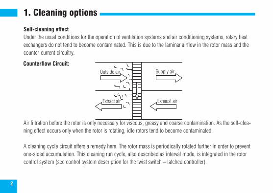
Self-cleaning effectUnder the usual conditions for the operation of ventilation systems and air conditioning systems, rotary heat exchangers do not tend to become contaminated. This is due to the laminar airflow in the rotor mass and the counter-current circuitry.
Air filtration before the rotor is only necessary for viscous, greasy and coarse contamination. As the self-clea-ning effect occurs only when the rotor is rotating, idle rotors tend to become contaminated.
A cleaning cycle circuit offers a remedy here. The rotor mass is periodically rotated further in order to prevent one-sided accumulation. This cleaning run cycle, also described as interval mode, is integrated in the rotor control system (see control system description for the twist switch – latched controller).
Outside air
Extract air
Supply air
Exhaust air
Counterflow Circuit:
3
2. Cleaning device
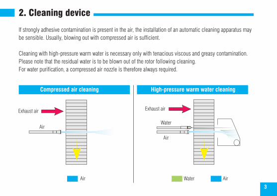
If strongly adhesive contamination is present in the air, the installation of an automatic cleaning apparatus may be sensible. Usually, blowing out with compressed air is sufficient.
Cleaning with high-pressure warm water is necessary only with tenacious viscous and greasy contamination. Please note that the residual water is to be blown out of the rotor following cleaning. For water purification, a compressed air nozzle is therefore always required.
Compressed air cleaning High-pressure warm water cleaning
Exhaust air
Air
Air
Water
Air Water Air
Exhaust air
4
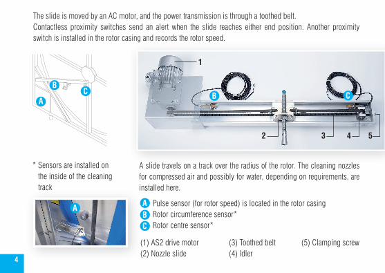
The slide is moved by an AC motor, and the power transmission is through a toothed belt.Contactless proximity switches send an alert when the slide reaches either end position. Another proximity switch is installed in the rotor casing and records the rotor speed.
A slide travels on a track over the radius of the rotor. The cleaning nozzles for compressed air and possibly for water, depending on requirements, are installed here.
Pulse sensor (for rotor speed) is located in the rotor casing Rotor circumference sensor* Rotor centre sensor*
A
BC
C
C
B
B
2 543
1
A
A
* Sensors are installed on the inside of the cleaning track
A
(1) AS2 drive motor(2) Nozzle slide
(3) Toothed belt(4) Idler
(5) Clamping screw
5
Following each rotation of the rotor, the cleaning apparatus advances by the width of a nozzle stream. This allows gap-free cleaning.
When the cleaning apparatus is switched off, the carriage is positioned on the periphery of the rotor. The cleaning procedure can be started either by a built-in weekly time switch, by an external switch or by the Start switch under the display.
Caution: Ensure that the heat exchanger wheel is released when starting cleaning and is turning for the whole time the program is running. When the cleaning device is operating, the nozzle slide continuously travels to the centre of the rotor. When the sensor reaches the centre, the air and possibly water cleaning begins.
A relay output for warm water and a compressed air valve are available. When the carriage reaches the periphery of the rotor, the water valve relay falls and the rotor is dried with compressed air during the return movement.
On reaching the centre sensor, the air relay switches off and the carriage travels to the starting position. During the cleaning procedure, the rotor runs with variable speed under the control of the AS2 control system.
The external control signal (0 - 10 Volt) is not processed during the cleaning procedure, so this process should be carried out during the idle times.
6
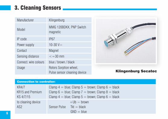
3. Cleaning Sensors
Manufacturer Klingenburg
ModelMMG 120BDKX, PNP Switchmagnetic
IP code IP67
Power supply 10-30 V=
Contact Magnet
Sensing distance <=30 mm
Connect. wire colours blue / brown / black
Usage Rotors Sorption wheel,Pulse sensor cleaning device Klingenburg Secatec
Connection to controller:
KR4/7 KR15 and PremiumKS 4/7/15
Clamp 4 = blue; Clamp 5 = brown; Clamp 6 = blackClamp 6 = blue; Clamp 7 = brown; Clamp 8 = blackClamp 4 = blue; Clamp 5 = brown; Clamp 6 = black
to cleaning device AS2
+Ub = brownSensor Pulse Tkt = black GND = blue
7
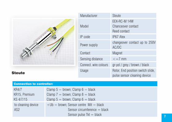
Manufacturer Steute
ModelEEX-RC-M 14WChanceover contactReed contact
IP code IP67 Atex
Power supplychangeover contact up to 250V AC/DC
Contact Magnet
Sensing distance <=7 mm
Connect. wire colours gr-yel / grey / brown / black
Usage Rotor, End position switch slide, pulse sensor cleaning device
Steute
Connection to controller:
KR4/7 KR15, Premium KS 4/7/15
Clamp 5 = brown; Clamp 6 = blackClamp 7 = brown; Clamp 8 = blackClamp 5 = brown; Clamp 6 = black
to cleaning device AS2
+Ub = brown; Sensor centre Mit = black Sensor circumference = black Sensor pulse Tkt = black
8
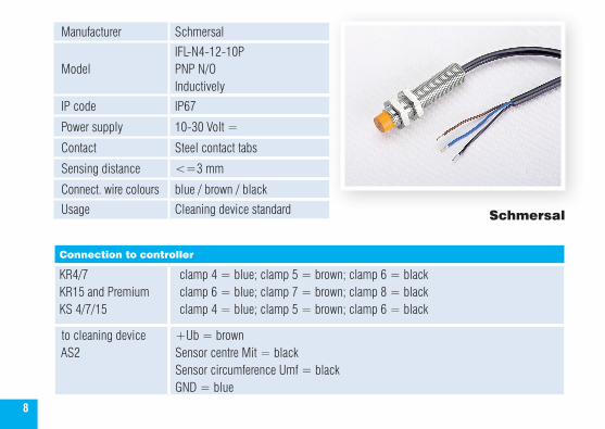
Manufacturer Schmersal
ModelIFL-N4-12-10PPNP N/OInductively
IP code IP67
Power supply 10-30 Volt =
Contact Steel contact tabs
Sensing distance <=3 mm
Connect. wire colours blue / brown / black
Usage Cleaning device standard Schmersal
Connection to controller
KR4/7KR15 and PremiumKS 4/7/15
clamp 4 = blue; clamp 5 = brown; clamp 6 = blackclamp 6 = blue; clamp 7 = brown; clamp 8 = blackclamp 4 = blue; clamp 5 = brown; clamp 6 = black
to cleaning device AS2
+Ub = brownSensor centre Mit = blackSensor circumference Umf = blackGND = blue
9
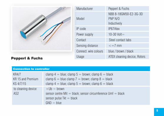
Manufacturer Pepperl & Fuchs
ModelNBB 8-18GM50-E2-3G-3DPNP N/OInductively
IP code IP67Atex
Power supply 10-30 Volt=
Contact Steel contact tabs
Sensing distance <=7 mm
Connect. wire colours blue / brown / black
Usage ATEX cleaning decice, RotorsPepperl & Fuchs
Connection to controller
KR4/7KR 15 and PremiumKS 4/7/15
clamp 4 = blue; clamp 5 = brown; clamp 6 = blackclamp 6 = blue clamp 7 = brown; clamp 8 = blackclamp 4 = blue; clamp 5 = brown; clamp 6 = black
to cleaning device AS2
+Ub = brown sensor centre Mit = black; sensor circumference Umf = blacksensor pulse Tkt = blackGND = blue
10
4. AS2 Cleaning Control System
Functional characteristics
Processor-controlled monitoring of the cleaning sequence
Coloured display
Detailed error messages
Menu navigation
Cleaning takes place from the inside to the outside (the contaminated water runs towards the outside)
11
Functional description
The cleaning control system enables the automatic, electronic cleaning of the contaminated thermal mass of a rotary heat exchanger.
Standby indicates readiness for operation. A start signal from an external contact, the start button or an optional time switch activates the cleaning procedure.
Following the start command, the carriage travels without media to the centre of the rotor. When the sensor reaches the centre, the cleaning procedure itself begins and the rotor rotates. Caution: The heat exchanger wheel must be released at all times while cleaning.
The relays switch on the solenoid valves for air and water. Due to the rotation of the rotor, the clock sensor receives the first pulse and the carriage is driven towards the periphery. The carriage should advance by no more than one nozzle width; otherwise, the cleaning will not be so effective.
This procedure is repeated until the cleaning carriage reaches the periphery of the sensor. The direction of travel then changes and the water relay falls. In order to remove the water from the thermal mass, the clea-ning carriage then executes return movement with compressed air.
On reaching the centre of the sensor, the relay for air switches off and the carriage travels to the park position at the periphery of the rotor. The cleaning procedure is now completed.
12
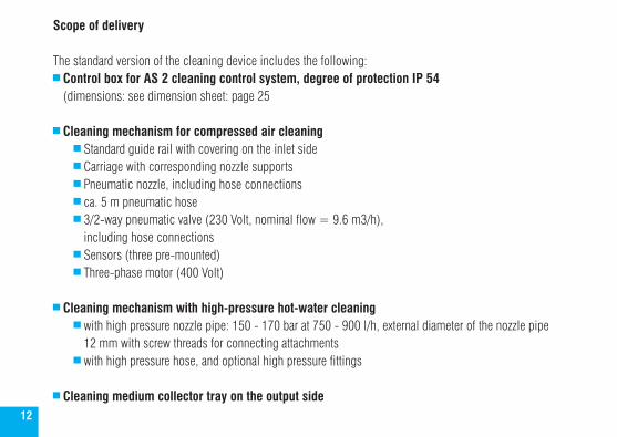
Scope of delivery
The standard version of the cleaning device includes the following: Control box for AS 2 cleaning control system, degree of protection IP 54 (dimensions: see dimension sheet: page 25
Cleaning mechanism for compressed air cleaning Standard guide rail with covering on the inlet side Carriage with corresponding nozzle supports Pneumatic nozzle, including hose connections ca. 5 m pneumatic hose 3/2-way pneumatic valve (230 Volt, nominal flow = 9.6 m3/h),
including hose connections Sensors (three pre-mounted) Three-phase motor (400 Volt)
Cleaning mechanism with high-pressure hot-water cleaning with high pressure nozzle pipe: 150 - 170 bar at 750 - 900 l/h, external diameter of the nozzle pipe
12 mm with screw threads for connecting attachments with high pressure hose, and optional high pressure fittings
Cleaning medium collector tray on the output side
13
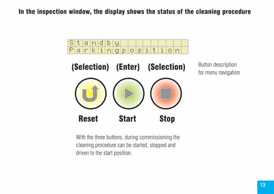
In the inspection window, the display shows the status of the cleaning procedure
(Selection) (Enter) (Selection)
Reset Start Stop
With the three buttons, during commissioning the cleaning procedure can be started, stopped and driven to the start position.
Button description for menu navigation
P a r k i n g p o s i t i o nS t a n d b y
14
3.4 Connection and commissioning
The mechanical components (rail, carriage, motor, supports, and sensors) are pre-mounted and must be attached to the frame with screws. The frame is also prepared with rivet-down nuts. Adjust the pneumatic nozzles and, if necessary, the high-pressure nozzles so that these end around 20 - 30 mm before the thermal mass. Attention: The nozzle stream must impinge perpendicular to the thermal mass! Control whether the inductive proximity switches are correctly positioned. The metal vanes of the carriage must be positioned around 2 mm away from the sensors. This requires adjusting the clamping block at the end of the rail to loosen the toothed belt. After setting the position switches, position the cleaning carriage in its centre position and tension the toothed belt again. For the correct connection of the centre and peripheral sensors, an LED in the AS 2 control system lights up over the respective terminals on contact. Connect the AS 2 control system according to the terminal plan. Switch on the mains voltage. Adjust the clock sensor on the periphery of the rotor. The clock sensor must receive one pulse per rotor revolution. (sensing distance around 20 mm) For commissioning, the cleaning control is equipped with three buttons:
Reset (return to the start position), Start and Stop..
15
Start the cleaning procedure with the Start button. The cleaning carriage must continuously drive towards the centre of the rotor. If this is not the case, stop cleaning and reverse the direction of rotation of the motor by switching two phases of the motor. When the direction of travel is correct (after changing the direction of rotation, restart the cleaning control), the carriage drives to the centre of the sensor and then begins the actual cleaning process. You can now control the carriage feed. Per clock signal, the carriage may not travel more than one nozzle width. In the cleaning control menu, the operating time of the carriage can be set to a value between 0.5 – 2.5 seconds (default setting 1 second).
After mechanically and electrically controlling the cleaning procedure, execute a so-called teach-in run with the AS 2 control system (see Section 5 Menu navigation on page 16). During the teach-in run the cleaning carriage travels without media at maximum wheel speed over the entire cleaning procedure and counts the pulses during cleaning and during dry travel and stores these internally with 5% safety margin as limit values. This procedure serves for the monitoring of the sensors in normal cleaning operation. In the case of a defect with the sensors, the AS 2 cleaning control system issues an error message due to exceeding the internal limit value, which remains and switches the media off. This prevents the mechanical destruction of the cleaning apparatus and the continued flow of the media.
Attention: When the operating time or the tolerance values are changed in the menu, a teach-in run automat-ically takes place with the next start of the cleaning procedure.
16
5. Menu navigation
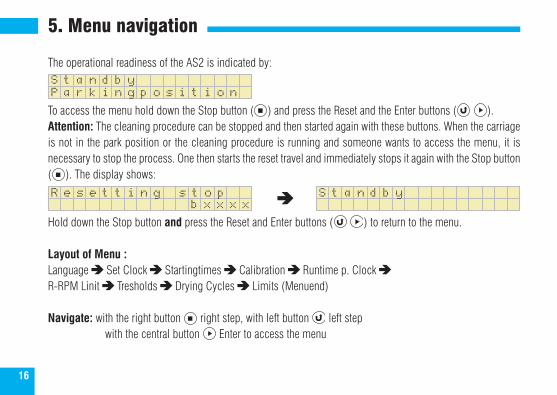
The operational readiness of the AS2 is indicated by:
To access the menu hold down the Stop button ( ) and press the Reset and the Enter buttons ( ).Attention: The cleaning procedure can be stopped and then started again with these buttons. When the carriage is not in the park position or the cleaning procedure is running and someone wants to access the menu, it is necessary to stop the process. One then starts the reset travel and immediately stops it again with the Stop button ( ). The display shows:
Hold down the Stop button and press the Reset and Enter buttons ( ) to return to the menu.
Layout of Menu :Language Set Clock Startingtimes Calibration Runtime p. Clock R-RPM Linit Tresholds Drying Cycles Limits (Menuend)
Navigate: with the right button right step, with left button left step with the central button Enter to access the menu
P a r k i n g p o s i t i o nS t a n d b y
b x x x xR e s e t t i n g s t o p
S t a n d b y
17
P r o g . m o d e
D e u t s c h
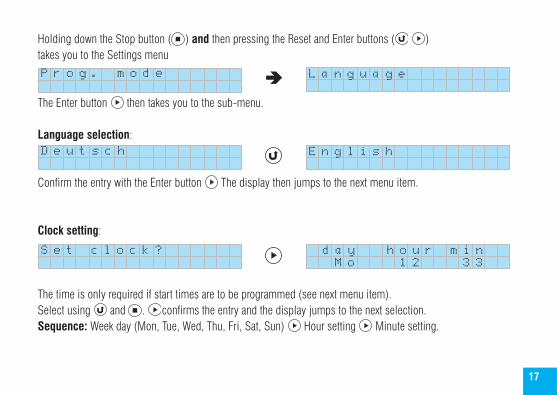
Holding down the Stop button ( ) and then pressing the Reset and Enter buttons ( ) takes you to the Settings menu
The Enter button then takes you to the sub-menu.
Language selection:
Confirm the entry with the Enter button The display then jumps to the next menu item.
Clock setting:
The time is only required if start times are to be programmed (see next menu item). Select using and . confirms the entry and the display jumps to the next selection.Sequence: Week day (Mon, Tue, Wed, Thu, Fri, Sat, Sun) Hour setting Minute setting.
L a n g u a g e
E n g l i s h
d a y h o u r m i nS e t c l o c k ? M o 1 2 3 3
18
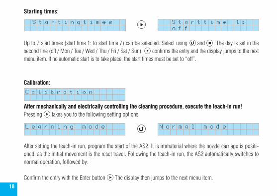
Starting times:
Up to 7 start times (start time 1: to start time 7) can be selected. Select using and . The day is set in the second line (off / Mon / Tue / Wed / Thu / Fri / Sat / Sun). confirms the entry and the display jumps to the next menu item. If no automatic start is to take place, the start times must be set to “off”.
Calibration:
After mechanically and electrically controlling the cleaning procedure, execute the teach-in run!Pressing takes you to the following setting options:
After setting the teach-in run, program the start of the AS2. It is immaterial where the nozzle carriage is positi-oned, as the initial movement is the reset travel. Following the teach-in run, the AS2 automatically switches to normal operation, followed by:
Confirm the entry with the Enter button The display then jumps to the next menu item.
N o r m a l m o d e L e a r n i n g m o d e
C a l i b r a t i o n
S t a r t i n g t i m e s o f f S t a r t t i m e 1 :
19
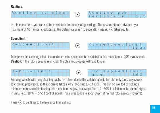
Runtime:
In this menu item, you can set the travel time for the cleaning carriage. The nozzles should advance by a maximum of 10 mm per clock pulse. The default value is 1.5 seconds. Pressing takes you to:
Speedlimit:
To improve the cleaning effect, the maximum rotor speed can be restricted in this menu item (100% max. speed). Caution: If the rotor speed is restricted, the cleaning process will take longer.
For large wheels with long cleaning tracks (>1.5m), due to the variable speed, the rotor only turns very slowly as cleaning progresses, so that cleaning takes a very long time (3-5 hours). This can be avoided by setting a minimum rotor speed limit using this menu item. Adjustment range from 10 - 50% in relation to the control signal in Volts (e.g.: 30 % = 3 Volt control signal. That corresponds to about 3 rpm at normal rotor speeds (10 rpm)).
Press to continue to the tolerance limit setting:
R u n t i m e p . c l o c k
T a k t i m p u l s 1 , 5 R u n t i m e p e r
R - S p e e d l i m i t
1 0 0 %R i n s e S p e e d l i m i t
R - M i n - L i m i t m i n : 3 0 % C o i l s p e e d l i m i t
20
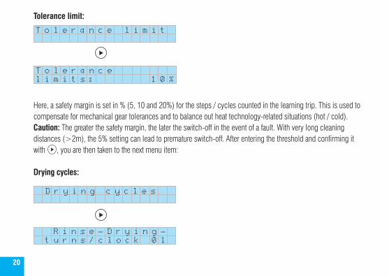
Tolerance limit:
Here, a safety margin is set in % (5, 10 and 20%) for the steps / cycles counted in the learning trip. This is used to compensate for mechanical gear tolerances and to balance out heat technology-related situations (hot / cold).Caution: The greater the safety margin, the later the switch-off in the event of a fault. With very long cleaning distances (>2m), the 5% setting can lead to premature switch-off. After entering the threshold and confirming it with , you are then taken to the next menu item: Drying cycles:
T o l e r a n c e l i m i t
l i m i t s : 1 0 %T o l e r a n c e
D r y i n g c y c l e s
t u r n s / c l o c k 0 1 R i n s e - D r y i n g -
21
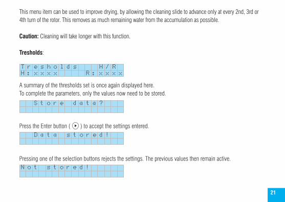
This menu item can be used to improve drying, by allowing the cleaning slide to advance only at every 2nd, 3rd or 4th turn of the rotor. This removes as much remaining water from the accumulation as possible.
Caution: Cleaning will take longer with this function.
Tresholds:
A summary of the thresholds set is once again displayed here.To complete the parameters, only the values now need to be stored.
Press the Enter button ( ) to accept the settings entered.
Pressing one of the selection buttons rejects the settings. The previous values then remain active.
H : x x x x R : x x x x T r e s h o l d s H / R
S t o r e d a t a ?
D a t a s t o r e d !
N o t s t o r e d !
22
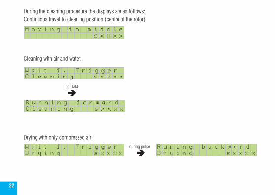
During the cleaning procedure the displays are as follows: Continuous travel to cleaning position (centre of the rotor)
Cleaning with air and water:
Drying with only compressed air:.
s x x x x M o v i n g t o m i d d l e
D r y i n g s x x x x W a i t f . T r i g g e r
D r y i n g s x x x x R u n i n g b a c k w a r dduring pulse
C l e a n i n g s x x x x R u n n i n g f o r w a r d
C l e a n i n g s x x x x W a i t f . T r i g g e r
bei Takt
23
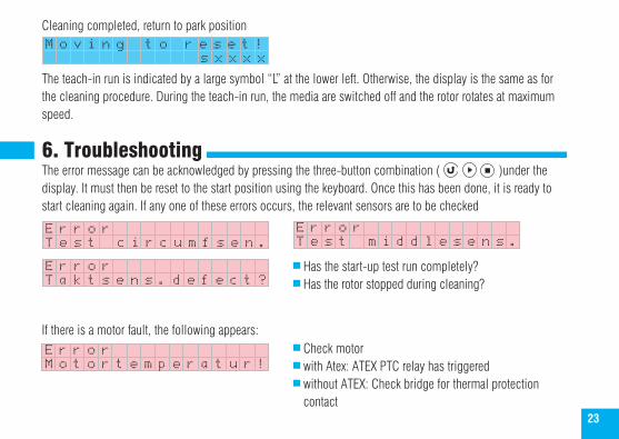
Cleaning completed, return to park position
The teach-in run is indicated by a large symbol “L” at the lower left. Otherwise, the display is the same as for the cleaning procedure. During the teach-in run, the media are switched off and the rotor rotates at maximum speed.
6. TroubleshootingThe error message can be acknowledged by pressing the three-button combination ( )under the display. It must then be reset to the start position using the keyboard. Once this has been done, it is ready to start cleaning again. If any one of these errors occurs, the relevant sensors are to be checked
If there is a motor fault, the following appears:
E r r o r
M o v i n g t o r e s e t !s x x x x
T e s t c i r c u m f s e n . E r r o rT e s t m i d d l e s e n s .
E r r o r
E r r o r
T a k t s e n s . d e f e c t ?
M o t o r t e m p e r a t u r ! Check motor with Atex: ATEX PTC relay has triggered without ATEX: Check bridge for thermal protection contact
Has the start-up test run completely? Has the rotor stopped during cleaning?

24
Cleaning carriage positioned in the centre of the rail: Check the step sensor in the rotor (switching distance) Rotate the magnet in front of the sensor and measure whether there is 24 Volt DC between the blue and black. If not, replace the sensor.
check the timing belt Check the rotor regulator:
is there a fault? is the regulator released? is the mains voltage present? In case of power failure:
If the power supply to the AS2 is interrupted while cleaning, an error message is generated when the power is switched back on.
This can be reset in one of two ways: The error message is acknowledged by setting the start command again and the cleaning slide automatically resets to the start position. When this has been done, cleaning can be restarted. By pressing the 3-button combination ( ) under the display. It must then be reset to the start position using the keyboard. Once this has been done, it is ready to start cleaning again.
Caution: The AS2 has a resettable fuse in the control circuit. It can be reset by briefly disconnecting the AS2 from the power (approx. 1 min.).
C l e a n i n g i n t e r r E r r o r
25
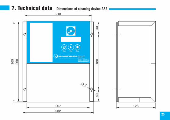
7. Technical data Dimensions of cleaning device AS2
26
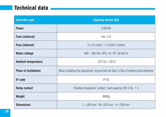
Technical data
Controller type Cleaning device AS2
Power 0,09 kW
Fuse (external) min. 4 A
Fuse (internal) 3 x 1A motor / 1 x 0,08 A Control
Mains voltage 380 - 420 Volt 3Ph / N / PE 50-60 Hz
Ambient temperature -10°C to +40°C
Place of installation When installing the equipment, ensure that the floor is free of shaking and vibrations
IP code IP 54
Relay contact Floating changeover contact, load capacity 250 V AC, 1 A
Weight 3000g
Dimensions L=265 mm W=232 mm H=128 mm
27
Maintenance notices (e.g. V-belts re-tensioned on:)
28
1AT 1AT 1AT 0,08AT
N
L1230 V ~for Coil
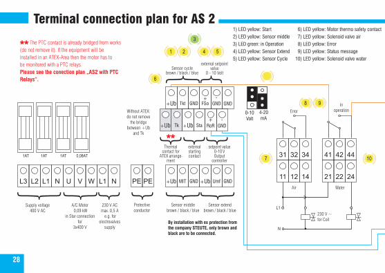
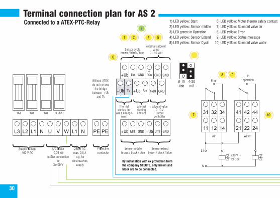
1) LED yellow: Start2) LED yellow: Sensor middle3) LED green: in Operation4) LED yellow: Sensor Extend5) LED yellow: Sensor Cycle
6) LED yellow: Motor thermo safety contact 7) LED yellow: Solenoid valve air 8) LED yellow: Error 9) LED yellow: Status message10) LED yellow: Solenoid valve water
L3 L2 L1 N U V W L1 N PE 11
31
12
32
14
34
21
41
22
42
24
44
PE +Ub
+Ub
+Ub
MIT
Tkt
Tk
GND
GND
+Ub
+Ub
+FSo
Sta
Umf
-GND
+RoR
GND
GND
-GND
0-10Volt
4-20 mA
Supply voltage400 V AC
230 V ACmax. 0,5 A
e.g. for electrovalves
supply
Protective conductor
Sensor middlebrown / black / blue
Sensor extendbrown / black / blue
Thermal contact for
ATEX arrange-ment
external starting contact
setpoint value 0-10 VOutput
controller
Sensor cycle brown / black / blue
Error
Air
inoperation
Water
external setpoint value
0 - 10 Volt
By installation with ex protection from the company STEUTE, only brown and black are to be connected.
A/C Motor 0,09 kW
in Star connection for
3x400 V
1
6
7
8
10
9
2 4 5
3
Without ATEX:do not remove
the bridgebetween +Ub
and Tk
Terminal connection plan for AS 2
The PTC contact is already bridged from works(do not remove it). If the equipment will beinstalled in an ATEX-Area then the motor has tobe monitored with a PTC relays.Please see the conection plan „AS2 with PTCRelays“.
{{
-
{+
Priority/summerspeed
Running control
black
brown
blue
Control unit release
Thermal contact/resistor
0 - 20 mA4 - 20 mA
0 - 10 V
Analogue output
0 - 10 V DC
Jumper position
Dedu
stin
g in
put
PEPE
PEU
VW
12
34
56
78
910
1112
13
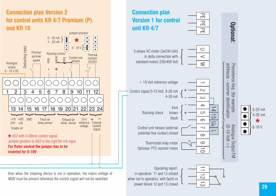
3-phase AC motor (3x230 Volt)in delta connection with
standard motors 230/400 Volt
+ 10 Volt reference voltage
Control signal 0-10 Volt, 0-20 mA4-20 mA
+
--
+blue
brownblack
Running check
Control unit release (external potential free contact closed
Thermostat relay motorOptional: PTC-resistor motor
Operating report: in operation: 11 and 13 closed
when not in operation, with faults or power failure 12 and 13 closed
1415
Ua
L
Analogue Output FM(0-10 Volt =
)Precedence freq. (for exam
ple: antifreeze - sum
mer identification
Optional:
0-20 mA4-20 mA
0-10 V
Connection plan Version 2for control units KR 4/7 Premium (P)and KR 15
Connection plan Version 1 for controlunit KR 4/7
Also when the cleaning device is not in operation, the mains voltage of 400V must be present otherwise the control signal will not be switched
1 2 3 4 5 6 7 8 9 10 11 12
13 14 15 16 17 18 19 20 21 22 23 24
Supply air
Fresh airtemp.sensor
Exhaust airtemp. sensor External
control signal
10 V reference voltage
+
GND+Ub24V
4-20mA
AS2 with 4-20mA control signalJumper position in AS2 to the right for mA input For Rotor control the jumper has to be inserted for 0-10V
29
30
1AT 1AT 1AT 0,08AT
N
L1
L3 L2 L1 N U V W L1 N PE 11
31
12
32
14
34
21
41
22
42
24
44
PE +Ub
+Ub
+Ub
MIT
Tkt
Tk
GND
GND
+Ub
+Ub
+FSo
Sta
Umf
-GND
+RoR
GND
GND
-GND
1
6
8
107
9
2 4 5
3
230 V ~for Coil
1) LED yellow: Start2) LED yellow: Sensor middle3) LED green: in Operation4) LED yellow: Sensor Extend5) LED yellow: Sensor Cycle
6) LED yellow: Motor thermo safety contact 7) LED yellow: Solenoid valve air 8) LED yellow: Error 9) LED yellow: Status message10) LED yellow: Solenoid valve water
0-10Volt
4-20 mA
Supply voltage400 V AC
230 V ACmax. 0,5 A
e.g. for electrovalves
supply
Protective conductor
Sensor middlebrown / black / blue
Sensor extendbrown / black / blue
Thermal contact for
ATEX arrange-ment
external starting contact
setpoint value 0-10 VOutput
controller
Sensor cycle brown / black / blue
Error
Air
inoperation
Water
external setpoint value
0 - 10 Volt
By installation with ex protection from the company STEUTE, only brown and black are to be connected.
A/C Motor 0,09 kW
in Star connection for
3x400 V
Without ATEX:do not remove
the bridgebetween +Ub
and Tk
Terminal connection plan for AS 2Connected to a ATEX-PTC-Relay
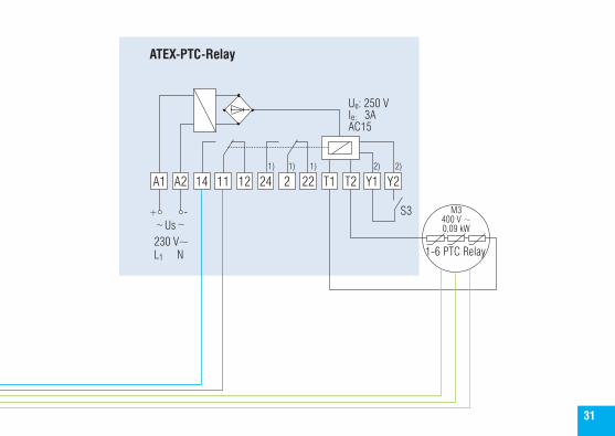
A1 A2 14 11 12 24 2 22 T1 T2 Y1 Y2
~ ~+ -
Us230 V~L1 N
S3
1-6 PTC Relay
Ue: 250 Vle: 3AAC15
M3400 V ~0,09 kW
1) 1) 1) 2) 2)
ATEX-PTC-Relay
31

Klingenburg GmbHBoystraße 11545968 GladbeckGermany Tel.: +49-20 43-96 36-0 Fax: +49-20 43-7 23 62E-mail: [email protected] www.klingenburg.de
E N E R G Y R E C O V E R Y
AS2
0508
14 e
ngl