Embed Size (px)
Citation preview
Page 1 / 1
Edition du : Issue Dated :
20/06/2011
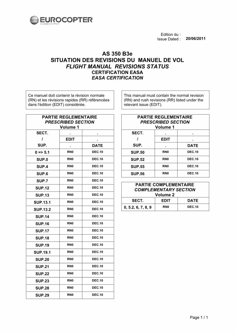
AS 350 B3e
SITUATION DES REVISIONS DU MANUEL DE VOL FLIGHT MANUAL REVISIONS STATUS
CERTIFICATION EASA EASA CERTIFICATION
Ce manuel doit contenir la révision normale (RN) et les révisions rapides (RR) référencées dans l'édition (EDIT) considérée.
This manual must contain the normal revision (RN) and rush revisions (RR) listed under the relevant issue (EDIT).
PARTIE REGLEMENTAIRE
PRESCRIBED SECTION Volume 1
. .
EDIT .
SECT. /
SUP. . DATE
0 => 5.1 RN0 DEC.10
SUP.0 RN0 DEC.10
SUP.4 RN0 DEC.10
SUP.6 RN0 DEC.10
SUP.7 RN0 DEC.10
SUP.12 RN0 DEC.10
SUP.13 RN0 DEC.10
SUP.13.1 RN0 DEC.10
SUP.13.2 RN0 DEC.10
SUP.14 RN0 DEC.10
SUP.16 RN0 DEC.10
SUP.17 RN0 DEC.10
SUP.18 RN0 DEC.10
SUP.19 RN0 DEC.10
SUP.19.1 RN0 DEC.10
SUP.20 RN0 DEC.10
SUP.21 RN0 DEC.10
SUP.22 RN0 DEC.10
SUP.23 RN0 DEC.10
SUP.28 RN0 DEC.10
SUP.29 RN0 DEC.10
PARTIE REGLEMENTAIRE PRESCRIBED SECTION
Volume 1 . .
EDIT .
SECT. /
SUP. . DATE
SUP.50 RN0 DEC.10
SUP.52 RN0 DEC.10
SUP.55 RN0 DEC.10
SUP.56 RN0 DEC.10
PARTIE COMPLEMENTAIRE
COMPLEMENTARY SECTION
Volume 2
SECT. EDIT DATE
0, 5.2, 6, 7, 8, 9 RN0 DEC.10


EASA APPROVED TITLE ORIGINAL ISSUE
A
FLIGHT MANUAL
AS 350 B3e
EASA TYPE CERTIFICATE No. EASA.R.008
REGISTRATION No. SERIAL No.
APPROVED BY: European Aviation Safety Agency BY:
EASA approval No. 10035374 on June17, 2011
DATE:
THE EFFECTIVITY OF THIS MANUAL AT THE LATEST REVISION IS SPECIFIED ON THE LIST OF EFFECTIVE PAGES.
IT IS THE OPERATOR’S RESPONSIBILITY TO MAINTAIN THIS MANUAL IN A CURRENT STATUS IN ACCORDANCE WITH THE LIST OF EFFECTIVE PAGES.
THIS HANDOOK INCLUDES THE MATERIAL TO BE FURNISHED TO THE PILOT AS REQUIRED BY FAR-27 AND ADDITIONAL INFORMATION PROVIDED BY THE MANUFACTURER AND HAS BEEN APPROVED IN ACCORDANCE WITH THE EASA CERTIFICATION PROCEDURES. THE EASA FLIGHT MANUAL CONSISTS OF ALL UNCODED AND CODED IAI PAGES MARKED “EASA APPROVED”.
E U R O C O P T E R D i r e c t i o n T e c h n i q u e S u p p o r t Aéroport international Marseille-Provence 13725 Marignane Cedex – France


FLIGHT MANUAL AS 350 B3e
EASA APPROVED C ORIGINAL ISSUE
LIST OF TEMPORARY REVISION EFFECTIVE PAGES The manual contains the following additional yellow pages.
No. PAGE DATE No. PAGE DATE

FLIGHT MANUAL AS 350 B3e
D ORIGINAL ISSUE
LIST OF TEMPORARY REVISION (TR) PAGES REQUIRING NO APPROVAL
The manual contains the following additional yellow pages. No. PAGE DATE No. PAGE DATE
FLIGHT MANUAL
AS 350 B3e
EASA APPROVED A ORIGINAL ISSUE
E
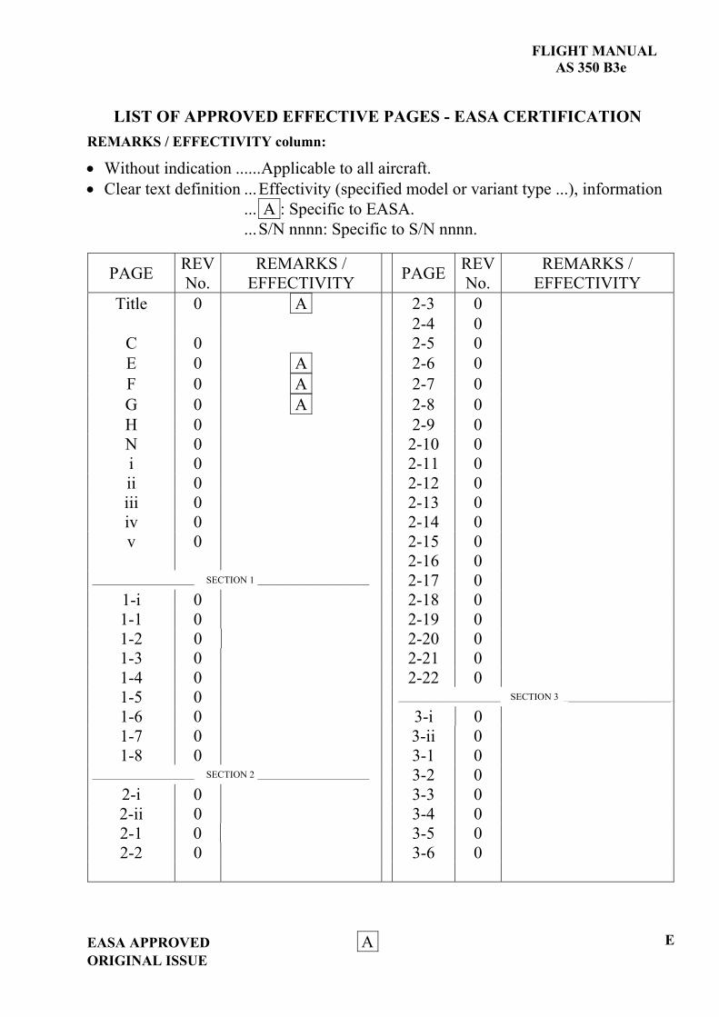
LIST OF APPROVED EFFECTIVE PAGES - EASA CERTIFICATION REMARKS / EFFECTIVITY column:
Without indication ......Applicable to all aircraft. Clear text definition ...Effectivity (specified model or variant type ...), information
... A : Specific to EASA.
...S/N nnnn: Specific to S/N nnnn.
PAGE REV No.
REMARKS / EFFECTIVITY PAGE REV
No. REMARKS /
EFFECTIVITY Title 0 A 2-3 0
2-4 0 C 0 2-5 0 E 0 A 2-6 0 F 0 A 2-7 0 G 0 A 2-8 0 H 0 2-9 0 N 0 2-10 0 i 0 2-11 0 ii 0 2-12 0 iii 0 2-13 0 iv 0 2-14 0 v 0 2-15 0 2-16 0
_____________________ SECTION 1 _______________________ 2-17 0 1-i 0 2-18 0 1-1 0 2-19 0 1-2 0 2-20 0 1-3 0 2-21 0 1-4 0 2-22 0 1-5 0 _____________________ SECTION 3 _______________________
1-6 0 3-i 0
1-7 0 3-ii 0 1-8 0 3-1 0
_____________________ SECTION 2 _______________________ 3-2 0 2-i 0 3-3 0 2-ii 0 3-4 0 2-1 0 3-5 0 2-2 0 3-6 0

FLIGHT MANUAL AS 350 B3e
F A EASA APPROVEDORIGINAL ISSUE
LIST OF APPROVED EFFECTIVE PAGES - EASA CERTIFICATION (CONT'D)
PAGE REV No.
REMARKS / EFFECTIVITY PAGE REV
No. REMARKS /
EFFECTIVITY 3-7 0 4-13 0 3-8 0 4-14 0
3-9 0 4-15 0 3-10 0 4-16 0 3-11 0 ____________________ SECTION 5 _______________________
3-12 0 5-i 0 3-13 0 5-ii 0 3-14 0 5-1 0 3-15 0 5-2 0 3-16 0 5-3 0 3-17 0 5-4 blank 0 3-18 0 5-5 0 3-19 0 5-6 0 3-20 0 5-7 0 3-21 0 5-8 0 3-22 0 5-9 0 3-23 0 5-10 0 3-24 0 5-11 0 3-25 0 5-12 0 3-26 0 5-13 0
_____________________ SECTION 4 _______________________ 5-14 0 4-i 0 4-ii 0 4-1 0 4-2 0 4-3 0 4-4 0 4-5 0
4-5A 0 4-5B 0 4-6 0 4-7 0 4-8 0 4-9 0 4-10 0 4-11 0 4-12 0

FLIGHT MANUAL
AS 350 B3e
EASA APPROVED A ORIGINAL ISSUE
G
LOG OF APPROVED NORMAL REVISIONS BASIC RFM REVISIONS - EFFECTIVITY EASA
NORMAL REVISION 0 - DECEMBER 2010 EASA approval No. 10035374 on June 17, 2011
Title New Flight Manual Revised
information All pages
Deleted information None

FLIGHT MANUAL AS 350 B3e
H EASA APPROVED ORIGINAL ISSUE
RECORD OF APPROVED REVISIONS
Rev. Date Inserted Rev. Date Inserted No. Approved Date Initials No. Approved Date Initials

FLIGHT MANUAL AS 350 B3e
N EASA APPROVED ORIGINAL ISSUE
CUSTOMIZATION
A/C: AS 350 B3e – S/N:
LIST OF ADDITIONAL APPROVED PAGES
PAGE REV No. REMARKS PAGE REV No. REMARKS

FLIGHT MANUAL
AS 350 B3e
MAIN TABLE OF CONTENTS
EASA APPROVED iORIGINAL ISSUE

FLIGHT MANUAL AS 350 B3e
ii EASA APPROVED ORIGINAL ISSUE
ORGANIZATION OF THE MANUAL
1 GENERAL NOTE
The helicopter shall be used in accordance with this Flight Manual and the applicable operational regulations.
The crew shall become familiar with the contents of this manual, special certification requirements and any information specific to customized configurations, and shall check all revisions and related requirements.
2 STRUCTURE OF THE MANUAL This manual contains legally approved information, together with additional manufacturer's information. - The approved information is contained in PART 1:
. SECTIONS 1, 2, 3, 4, 5.1,
. Supplements,
. Appendices. - The additional manufacturer's information is contained in PART 2:
. SECTIONS 5.2, 6, 7, 8 and 9,
. Appendices.
3 PAGE NUMBERING The numbering of pages within each section, each supplement or each appendix (SUP or APP) consists of the section number or designation, a dash and the consecutive number of the page beginning with "1"; e.g. for SECTION 3: 3-1, 3-2, etc. SUP17-1, APP1.0-2, etc. Figures are likewise numbered consecutively by section, such as Fig. 3-1, Fig. 3-2, etc. Exceptions: - The numbering of the Table of Contents pages preceding each section in this
manual consists of the section number, a dash and the consecutive Roman numeral (lower case) of the page, beginning with "i"; e.g. for SECTION 3: 3-i, 3-ii, etc.

FLIGHT MANUAL AS 350 B3e
EASA APPROVED iii ORIGINAL ISSUE
4 FLIGHT MANUAL SUPPLEMENTS
Information concerning optional equipment systems and procedures is covered by supplements. These are mini Flight Manuals covering any differences compared with the Regulatory Flight Manual information, section by section. The supplements are updated on an individual basis. A List of Supplements is provided in SUP.0 as an index listing the current supplements.
5 FLIGHT MANUAL APPENDIX Information concerning certification requirements, customization or complementary procedures may be covered by appendices. These are mini Flight Manuals covering any differences compared with the Flight Manual information, section by section. The appendix is updated on an individual basis, with a specific distribution.
6 EFFECTIVITY STATEMENTS 6.1 DEFINITION OF EFFECTIVITY IDENTIFICATION
The content of this manual applies to all the AS350B3e helicopter model variants listed on the title page and defined in this Section. However, certain portions of the manual may apply to only specific model variants, serial numbered helicopters, etc. Therefore, an effectivity identification system is used to indicate where differences brought about by helicopter modifications, Service Bulletins, customer options, variations of the basic model helicopter, etc. occur within the manual.

FLIGHT MANUAL AS 350 B3e
iv EASA APPROVED ORIGINAL ISSUE
6.2 INCORPORATING PAGES HAVING ENTIRE PAGE EFFECTIVITY STATEMENTS
CAUTION
Compare the effectivity statements of those pages having identical page numbers and determine which pages apply to your helicopter (front and backpage, if necessary). Insert these pages in the FLM binder. Discard these pages which do not apply. Do not discard pages having a page effectivity statement "After SB......" that at present may not apply to the helicopter unless however, it is absolutely certain that the stated Service Bulletin will never be incorporated.
7 REVISION SERVICE This manual is updated through Normal Revisions or Temporary Revisions. 7.1 NORMAL REVISIONS
Each Normal Revision is accompanied by an instruction sheet summarizing the main points affected by the change, and explaining how to incorporate the revised pages in the Manual (the instruction sheet may be filed separately from the Manual). Part 1, Part 2, each supplement and each appendix are revised separately. Normal Revisions fully or partially update the Manual. The revised pages either replace or supplement the existing pages. The Manual effectivity is specified by the new list of effective pages. The Normal Revisions are identified in numerical order.
NOTE A significant revision which includes a structural change in the manual breakdown for example, may lead to a change in the ISSUE of the Manual and to starting again with a Normal Revision 0.

FLIGHT MANUAL AS 350 B3e
EASA APPROVED v ORIGINAL ISSUE
7.2 TEMPORARY REVISIONS Several Temporary Revisions may be issued between two Normal Revisions. The new information given on yellow pages must be inserted opposite the existing pages to be modified or to be supplemented. The reader will have to insert these pages according to the numbering of the pages. The revised pages are indicated on a separate list. Temporary Revisions are identified by the number of the next Normal Revision together with a letter suffix in normal alphabetical order. Temporary Revisions are cancelled by the next Normal Revision bearing the same number, unless they are confirmed by a new Temporary Revision bearing another identification code. Temporary Revisions are delivered on yellow paper.
7.3 PROCEDURE FOR DOCUMENTARY CHANGES IN THE FLIGHT MANUAL In the event of minor errors / changes (e.g. typing error, misprints) and changes on manufacturer's data pages, EUROCOPTER is authorized by EASA to release a revision which needs not to be certified by the authorities. In this case the procedures for a Normal Revision apply.
7.4 IDENTIFYING UPDATED INFORMATION Changes are indicated by a revision mark.

FLIGHT MANUAL AS 350 B3e
EASA APPROVED 1 - i ORIGINAL ISSUE
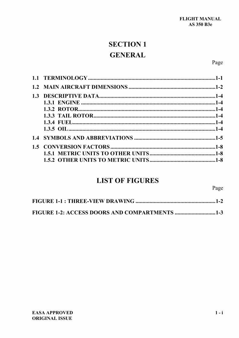
SECTION 1 GENERAL
Page
1.1 TERMINOLOGY...........................................................................................1-1 1.2 MAIN AIRCRAFT DIMENSIONS ..............................................................1-2 1.3 DESCRIPTIVE DATA...................................................................................1-4
1.3.1 ENGINE ................................................................................................1-4 1.3.2 ROTOR..................................................................................................1-4 1.3.3 TAIL ROTOR.......................................................................................1-4 1.3.4 FUEL......................................................................................................1-4 1.3.5 OIL.........................................................................................................1-4
1.4 SYMBOLS AND ABBREVIATIONS ..........................................................1-5 1.5 CONVERSION FACTORS ...........................................................................1-8
1.5.1 METRIC UNITS TO OTHER UNITS...............................................1-8 1.5.2 OTHER UNITS TO METRIC UNITS...............................................1-8
LIST OF FIGURES Page
FIGURE 1-1 : THREE-VIEW DRAWING .........................................................1-2
FIGURE 1-2: ACCESS DOORS AND COMPARTMENTS .............................1-3


FLIGHT MANUAL AS 350 B3e
EASA APPROVED 1 - 1 ORIGINAL ISSUE
1.1 TERMINOLOGY
Unless otherwise specified in the text, altitudes are pressure-altitudes (Hp), speeds are indicated airspeeds (IAS).
Warnings, Cautions and Notes are used throughout this manual to emphasize important and critical instructions and are used as follows:
WARNING
AN OPERATING PROCEDURE, PRACTICE, ETC., WHICH, IF NOT CORRECTLY FOLLOWED, COULD RESULT IN PERSONAL INJURY OR LOSS OF LIFE.
CAUTION
An operating procedure, practice, etc., which, if not strictly observed, could result in damage to, or destruction of helicopter parts or equipment.
NOTE An operating procedure, condition, etc., which is essential to highlight.
USE OF PROCEDURAL WORDS The concept of procedural word usage and intended meaning which has been adhered to in preparing this manual is as follows:
"Shall" has been used only when application of a procedure is mandatory.
"Should" has been used only when application of a procedure is recommended.
"May" and "need not" have been used only when application of a procedure is optional.
"Will" has been used only to indicate future event or action, never to indicate a mandatory procedure.

FLIGHT MANUAL AS 350 B3e
1 - 2 EASA APPROVED ORIGINAL ISSUE
1.2 MAIN AIRCRAFT DIMENSIONS
(*) Add 0.20 m (0.65 ft) when aircraft is fitted with high landing gear.
NOTE The values which vary according to weight are given at the maximum weight.
Figure 1-1: Three-view drawing
*

FLIGHT MANUAL AS 350 B3e
EASA APPROVED 1 - 3 ORIGINAL ISSUE
Figure 1-2: Access doors and compartments
0.50 m 0.75 m 1.64 ft 2.46 ft
0.76 m 0.85 m 2.49 ft 2.79 ft
Standard doors Sliding door
FLIGHT MANUAL AS 350 B3e
1 - 4 EASA APPROVED ORIGINAL ISSUE
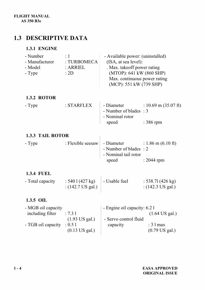
1.3 DESCRIPTIVE DATA 1.3.1 ENGINE - Number : 1 - Available power: (uninstalled) - Manufacturer : TURBOMECA (ISA, at sea level): - Model : ARRIEL . Max. takeoff power rating - Type : 2D (MTOP): 641 kW (860 SHP) Max. continuous power rating (MCP): 551 kW (739 SHP) 1.3.2 ROTOR - Type : STARFLEX - Diameter : 10.69 m (35.07 ft) - Number of blades : 3 - Nominal rotor speed : 386 rpm 1.3.3 TAIL ROTOR - Type : Flexible seesaw - Diameter : 1.86 m (6.10 ft) - Number of blades : 2 - Nominal tail rotor speed : 2044 rpm 1.3.4 FUEL - Total capacity : 540 l (427 kg) - Usable fuel : 538.7l (426 kg) : (142.7 US gal.) : (142.3 US gal.) 1.3.5 OIL - MGB oil capacity - Engine oil capacity : 6.2 l including filter : 7.3 l (1.64 US gal.) (1.93 US gal.) - Servo control fluid - TGB oil capacity : 0.5 l capacity : 3 l max (0.13 US gal.) (0.79 US gal.)

FLIGHT MANUAL AS 350 B3e
EASA APPROVED 1 - 5 ORIGINAL ISSUE
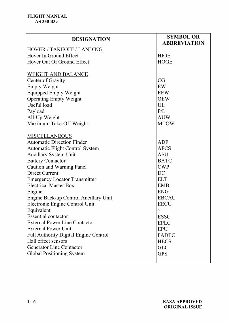
1.4 SYMBOLS AND ABBREVIATIONS
DESIGNATION SYMBOL OR ABBREVIATION
SPEEDS Calibrated airspeed Indicated airspeed True airspeed Never exceed speed Best rate of climb speed Rate of climb Rate of descent METEOROLOGY International Standard Atmosphere Outside Air Temperature Outside air pressure Relative air density Wind velocity ALTITUDE / HEIGHT Geometric altitude Pressure altitude Density altitude Radio altimeter height Height POWER / ENGINE PARAMETERS Maximum Continuous Power Maximum Takeoff Power Power Engine Health Check Rotor speed Engine generator speed Engine generator deviation indication Free turbine speed Torque Power turbine inlet temperature First Limitation Indicator
CAS IAS TAS VNE Vy R/C R/D ISA OAT p
Vw H Hp H HRA h MCP MTOP PWR EHC NR N1
N1 N2 TRQ TOT FLI
FLIGHT MANUAL AS 350 B3e
1 - 6 EASA APPROVED ORIGINAL ISSUE
DESIGNATION SYMBOL OR ABBREVIATION
HOVER / TAKEOFF / LANDING Hover In Ground Effect Hover Out Of Ground Effect WEIGHT AND BALANCE Center of Gravity Empty Weight Equipped Empty Weight Operating Empty Weight Useful load Payload All-Up Weight Maximum Take-Off Weight MISCELLANEOUS Automatic Direction Finder Automatic Flight Control System Ancillary System Unit Battery Contactor Caution and Warning Panel Direct Current Emergency Locator Transmitter Electrical Master Box Engine Engine Back-up Control Ancillary Unit Electronic Engine Control Unit Equivalent Essential contactor External Power Line Contactor External Power Unit Full Authority Digital Engine Control Hall effect sensors Generator Line Contactor Global Positioning System
HIGE HOGE CG EW EEW OEW UL P/L AUW MTOW ADF AFCS ASU BATC CWP DC ELT EMB ENG EBCAU EECU
ESSC EPLC EPU FADEC HECS GLC GPS
FLIGHT MANUAL AS 350 B3e
EASA APPROVED 1 - 7 ORIGINAL ISSUE
DESIGNATION SYMBOL OR ABBREVIATION
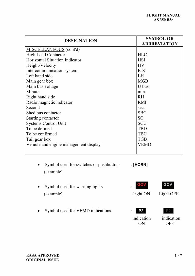
MISCELLANEOUS (cont'd) High Load Contactor Horizontal Situation Indicator Height-Velocity Intercommunication system Left hand side Main gear box Main bus voltage Minute Right hand side Radio magnetic indicator Second Shed bus contactor Starting contactor Systems Control Unit To be defined To be confirmed Tail gear box Vehicle and engine management display
HLC HSI HV ICS LH MGB U bus min. RH RMI sec. SBC SC SCU TBD TBC TGB VEMD
Symbol used for switches or pushbuttons : [HORN] (example)
Symbol used for warning lights : (example) Light ON Light OFF
Symbol used for VEMD indications : P2 ) P2 )
indication indication ON OFF
GOV GOV

FLIGHT MANUAL AS 350 B3e
1 - 8 EASA APPROVED ORIGINAL ISSUE
1.5 CONVERSION FACTORS 1.5.1 METRIC UNITS TO OTHER UNITS
1 cm = 0.3937 in 1 m = 3.2808 ft 1 km = 0.5400 NM 1 l = 0.2642 US gal 1 l = 0.2200 UK gal 1 kg = 2.2046 lb 1 bar = 14.5040 psi 1 km/h = 0.540 kt
1.5.2 OTHER UNITS TO METRIC UNITS
1 in = 2.5400 cm 1 ft = 0.3048 m 1 NM = 1.8520 km 1 US gal = 3.7850 l 1 UK gal = 4.5460 l 1 lb = 0.4536 kg 1 psi = 0.0689 bar 1.013 Hpa = 29.92 in.hg 1 kt = 1.852 km/h

FLIGHT MANUAL AS 350 B3e
EASA APPROVED 2 - i ORIGINAL ISSUE
SECTION 2 LIMITATIONS
Page
2.1 GENERAL.................................................................................................. 2-1 2.1.1 TYPE OF OPERATIONS ............................................................ 2-1 2.1.2 OCCUPANTS ................................................................................ 2-1 2.1.3 INSTRUMENT MARKINGS ...................................................... 2-1
2.2 WEIGHT AND BALANCE LIMITATIONS ......................................... 2-2 2.2.1 WEIGHT LIMITATION.............................................................. 2-2 2.2.2 LONGITUDINAL CG .................................................................. 2-2 2.2.3 LATERAL CG............................................................................... 2-3
2.3 FLIGHT ENVELOPE LIMITATIONS .................................................. 2-4 2.3.1 AIRSPEED LIMITATIONS ........................................................ 2-4 2.3.2 ALTITUDE LIMITATION.......................................................... 2-7 2.3.3 TEMPERATURE LIMITATIONS ............................................. 2-7 2.3.4 LANDING AND ROTOR STOPPING LIMITATIONS
ON SLOPE..................................................................................... 2-7 2.3.5 RUNNING LANDING LIMITATIONS ..................................... 2-7 2.3.6 MANEUVERING LIMITATIONS ............................................. 2-7
2.4 VEHICLE LIMITATIONS ...................................................................... 2-9 2.4.1 MAIN ROTOR LIMITATIONS.................................................. 2-9 2.4.2 TAKEOFF POWER...................................................................... 2-9 2.4.3 FIRST LIMITATION INDICATOR .......................................... 2-9 2.4.4 MAIN TRANSMISSION LIMITATIONS ............................... 2-10 2.4.5 ENGINE LIMITATIONS........................................................... 2-10 2.4.6 ELECTRICAL CIRCUIT LIMITATIONS.............................. 2-12
2.5 MISCELLANEOUS LIMITATIONS ................................................... 2-13 2.5.1 APPROVED FUELS................................................................... 2-13 2.5.2 APPROVED LUBRICANTS AND FLUIDS ............................ 2-16 2.5.3 BAGGAGE COMPARTMENT LOAD LIMITATIONS........ 2-18 2.5.4 CABIN COMPARTMENT LOAD LIMITATIONS ............... 2-18 2.5.5 MANDATORY EQUIPMENT .................................................. 2-18 2.5.6 OPTIONAL EQUIPMENT ........................................................ 2-18
2.6 PLACARDS.............................................................................................. 2-19

FLIGHT MANUAL AS 350 B3e
2 - ii EASA APPROVEDORIGINAL ISSUE
LIST OF FIGURES
Page
FIGURE 2-1 : LONGITUDINAL CG CHART ................................................. 2-2

FLIGHT MANUAL AS 350 B3e
EASA APPROVED 2 - 1 ORIGINAL ISSUE
2.1 GENERAL The helicopter is approved on the basis of the FAR part 27 “NORMAL” rotorcraft category. The helicopter shall be operated in compliance with the limitations of this section. 2.1.1 TYPE OF OPERATIONS
The helicopter is approved to operate: - by day and night in VFR.
NOTE Additional equipment may be required by operational regulations
The following are forbidden: - Aerobatic maneuvers. - Flight in falling snow without optional sand filter installed. - Flight in freezing rain or icing conditions. (visible moisture and temperatures conducive to producing ice). - In flight engine power reduction using twist grip control except for
engine failure training, emergency procedures referring to it or maintenance check procedures.
- In flight intentional complete VEMD cut-off (lane 1 + 2). 2.1.2 OCCUPANTS
- Minimum flight crew........................ : One pilot in right seat. - Maximum number of occupants
(including flight crew)...................... : Six. 2.1.3 INSTRUMENT MARKINGS
Limitations are marked on instruments with the following color code:
FLIGHT MANUAL AS 350 B3e
2 - 2 EASA APPROVED ORIGINAL ISSUE
On the VEMD, related numerical values of parameters are underlined: - in yellow when the parameter is in caution or takeoff power range, - in red when at or above a safety limit or maximum takeoff power.
Moreover, to attract attention, red underlining flashes. 2.2 WEIGHT AND BALANCE LIMITATIONS
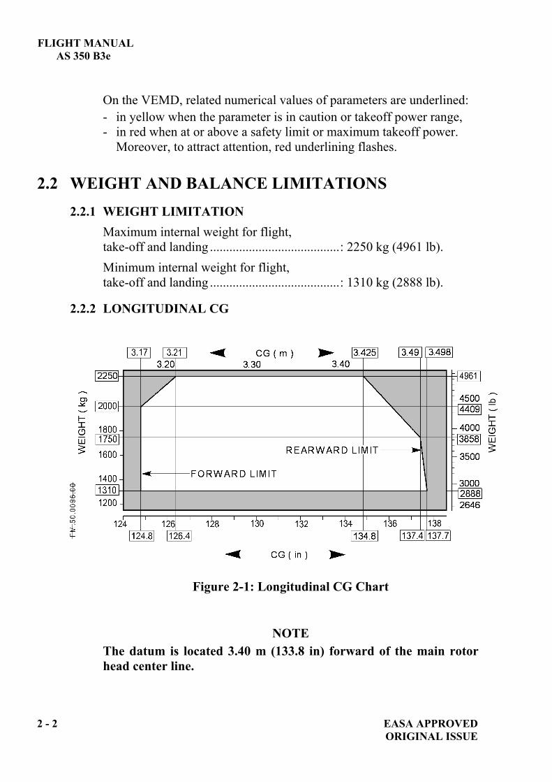
2.2.1 WEIGHT LIMITATION Maximum internal weight for flight, take-off and landing ........................................: 2250 kg (4961 lb). Minimum internal weight for flight, take-off and landing ........................................: 1310 kg (2888 lb).
2.2.2 LONGITUDINAL CG
Figure 2-1: Longitudinal CG Chart
NOTE The datum is located 3.40 m (133.8 in) forward of the main rotor head center line.

FLIGHT MANUAL AS 350 B3e
EASA APPROVED 2 - 3 ORIGINAL ISSUE
2.2.3 LATERAL CG
Maximum left CG......................................... : 0.18 m (7.08 in) Maximum right CG ...................................... : 0.14 m (5.51 in)
NOTE
The datum is located in the plane of symmetry of the helicopter.

FLIGHT MANUAL AS 350 B3e
2.3 FLIGHT ENVELOPE LIMITATIONS
2.3.1 AIRSPEED LIMITATIONS All airspeed limitations are Indicated Airspeeds.
2.3.1.1 With doors closed:
- When OAT < -30°C, calculated VNE power on must be reduced by 10 kt (18.5 km/h),
- When OAT < -20°C, calculated VNE power off must be reduced by 20 kt (37 km/h), with a minimum of 65 kt (120 km/h).
2.3.1.2 With doors open or removed:
NOTE Flight with any configuration not shown is prohibited. In all open doors configurations, loose objects shall not be in the cabin, cushions of unoccupied seats shall be removed and seat belts shall be stowed.
2 - 4 EASA APPROVED ORIGINAL ISSUE

FLIGHT MANUAL AS 350 B3e
EASA APPROVED 2 - 5 ORIGINAL ISSUE
Caption code used for open doors limitations: : door closed : door removed : sliding door closed : sliding door maneuvering in flight : sliding door open-locked or removed
Aircraft fitted with four standard doors (LH and RH hand doors)
I II IVa
VNE VNE 110 kt (204 km/h) or VNE*
b VNE 110 kt (204 km/h) or VNE* 110 kt (204 km/h) or VNE*
d 100 kt (185 km/h) or VNE* 110 kt (204 km/h) or VNE* 110 kt (204 km/h) or VNE*
(*) lowest value
Aircraft fitted with LH sliding door (optional) and RH standard doors
I II III IV
eVNE VNE 70 kt (130 km/h)
or VNE* 110 kt (204 km/h)
or VNE*
h 135 kt (250 km/h) or VNE*
110 kt (204 km/h) or VNE*
100 kt (185 km/h) or VNE*
110 kt (204 km/h) or VNE*
j 100 kt (185 km/h) or VNE*
110 kt (204 km/h) or VNE*
100 kt (185 km/h) or VNE*
110 kt (204 km/h) or VNE*
opening : 110 kt (204 km/h) or VNE*
closing : 80 kt (148 km/h) or VNE*
(*) lowest value
RH doors
LH doors
FLIGHT PROHIBITED
RH doors
LH doors

FLIGHT MANUAL AS 350 B3e
Caption code used for open doors limitations :
: door closed : door removed : sliding door closed
2 - 6 EASA APPROVED
: sliding door maneuvering in flight : sliding door open-locked or removed
Aircraft fitted with LH standard doors and RH sliding door (optional)
sliding door m i
V.
VNE 110 kt (204 km/h)or VNE*
100 kt (185 km/h)or VNE*
opening : 60 kt (111 km/h) or VNE*
mVNE 110 kt (204 km/h)
or VNE*110 kt (204 km/h)
or VNE*closing : 60 kt
(111 km/h) or VNE*
o
p100 kt (185 km/h)
or VNE*110 kt (204 km/h)
or VNE*110 kt (204 km/h)
or VNE*
(*) lowest value
Aircraft fitted with RH and LH sliding doors (optional)
I II
ht
V.
VNE 110 kt (204 km/h) or VNE*
100 kt (185 km/h) or VNE*
opening :60 kt (111 km/h) or VNE*
135 kt (250 km/h) or VNE*
110 kt (204 km/h) or VNE*
110 kt (204 km/h) or VNE*
closing :60 kt (111 km/h) or VNE*
x 100 kt (185 km/h) or VNE*
110 kt (204 km/h) or VNE*
110 kt (204 km/h)or VNE*
LH
FLIGHT PROHIBITED
LH
RH
opening : 60 kt (111 km/h) or VNE*
Closing : 60 kt (111 km/h) or VNE*
(*) lowest value FLIGHT PROHIBITED FLIGHT PROHIBITED
ORIGINAL ISSUE

FLIGHT MANUAL AS 350 B3e
EASA APPROVED 2 - 7 ORIGINAL ISSUE
2.3.2 ALTITUDE LIMITATION - Maximum operating altitude in flight: Hp = 23000 ft (7010 m)
2.3.3 TEMPERATURE LIMITATIONS - Minimum temperature ......................... : - 40°C - Maximum temperature ........................ : ISA+35°C
limited to +50°C For cold weather operations, refer to SUP.4.
2.3.4 LANDING AND ROTOR STOPPING LIMITATIONS ON SLOPE - Nose up................................................. : 10° - Nose down............................................ : 6° - Sideways............................................... : 8°
2.3.5 RUNNING LANDING LIMITATIONS Excluding emergencies and failures, maximum speed for performing: - running landings................................... : 40 kt (74 km/h)
2.3.6 MANEUVERING LIMITATIONS
Continued operation in servo transparency (where load feedback is felt in the controls) is prohibited. Maximum load factor is a combination of TAS, H and gross weight. Avoid such combinations at high values associated with high collective pitch. Transparency may be reached during maneuvers, steep turns, hard pull-up or when maneuvering near VNE. Self-correcting, the phenomenon will induce an un-commanded right cyclic load and an associated collective down reaction. However, even if the transparency feedback loads are fully controllable, immediate action is required to relieve the feed back loads: reduce the severity of the maneuver, follow the aircraft's natural reaction, let the collective pitch decrease naturally (avoid low pitch) and smoothly counteract the right cyclic motion. Transparency will disappear as soon as excessive loads are relieved.

FLIGHT MANUAL AS 350 B3e
2 - 8 EASA APPROVED ORIGINAL ISSUE
In maximum power configuration, decrease collective pitch slightly before initiating a turn, as for this maneuver the power requirement is increased.
In hover, avoid rotation faster than 6 sec. per full rotation.
FLIGHT MANUAL AS 350 B3e
EASA APPROVED 2 - 9 ORIGINAL ISSUE
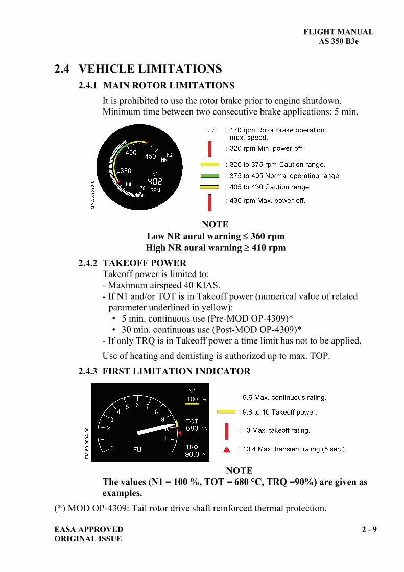
2.4 VEHICLE LIMITATIONS 2.4.1 1BMAIN ROTOR LIMITATIONS
It is prohibited to use the rotor brake prior to engine shutdown. Minimum time between two consecutive brake applications: 5 min.
NOTE
Low NR aural warning 360 rpm High NR aural warning 410 rpm
2.4.2 TAKEOFF POWER Takeoff power is limited to: - Maximum airspeed 40 KIAS. - If N1 and/or TOT is in Takeoff power (numerical value of related
parameter underlined in yellow): • 5 min. continuous use (Pre-MOD OP-4309)* • 30 min. continuous use (Post-MOD OP-4309)*
- If only TRQ is in Takeoff power a time limit has not to be applied. Use of heating and demisting is authorized up to max. TOP.
2.4.3 FIRST LIMITATION INDICATOR
NOTE
The values (N1 = 100 %, TOT = 680 °C, TRQ =90%) are given as examples.
(*) MOD OP-4309: Tail rotor drive shaft reinforced thermal protection.

FLIGHT MANUAL AS 350 B3e
2 - 10 EASA APPROVED ORIGINAL ISSUE
2.4.4 MAIN TRANSMISSION LIMITATIONS
TORQUE LIMITATIONS
NOTE 100 % torque corresponds to 535 kW at NR 386 rpm.
2.4.5 ENGINE LIMITATIONS
N2 LIMITATIONS
NOTE A rotor speed of NR 386 rpm corresponds to an N2 speed of 39158 rpm.
FLIGHT MANUAL AS 350 B3e
EASA APPROVED 2 - 11 ORIGINAL ISSUE
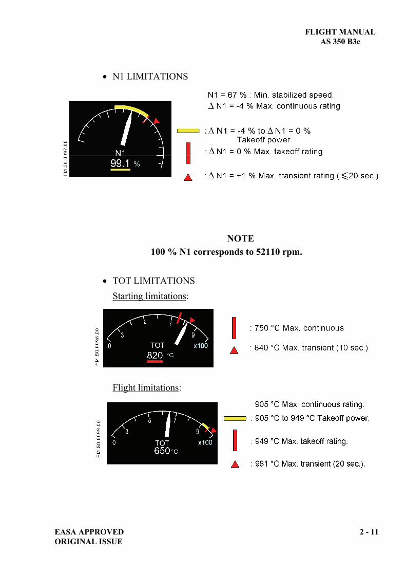
N1 LIMITATIONS
NOTE 100 % N1 corresponds to 52110 rpm.
TOT LIMITATIONS Starting limitations:
Flight limitations:

FLIGHT MANUAL AS 350 B3e
OIL TEMPERATURE LIMITATIONS
Oil temperature has variable limits that depend on N1. Minimum oil temperature before power application: - 0°C (Oil 5 cSt). - -10°C (Oil 3 to 3.9 cSt). During the oil warm up period, the engine must be run at idle rating.
OIL PRESSURE LIMITATIONS
Oil pressure has variable limits that depend on N1.
2.4.6 ELECTRICAL CIRCUIT LIMITATIONS
Maximum voltage ........................: 31.5 V (Rated voltage 26-29 V)
Maximum current ........................: 150 A Max. continuous. For 200 A Starter Generator (if installed),
refer to SUP.29.
2 - 12 EASA APPROVED ORIGINAL ISSUE

FLIGHT MANUAL AS 350 B3e
EASA APPROVED 2 - 13 ORIGINAL ISSUE
2.5 MISCELLANEOUS LIMITATIONS 2.5.1 APPROVED FUELS
NOTE 1 Commercial designations of authorized fuels are specified in the TURBOMECA documentation. NORMAL FUELS
(Fuels approved to operate throughout the flight envelope with no restrictions).
Specifications Type of fuel NATO
code FRANCE USA UK
Anti-ice additive included
Kerosene - 50 (AVTUR-FSII) (JP8) F 34 DCSEA 134
AIR 3405 MIL-T-83133
(JP8)
DEF STAN 91-87
D.ENG.RD 2453
Yes
Kerosene - 50 (AVTUR) (JP1) F 35 DCSEA 134
AIR 3405 ASTM-D-1655
JET A1
DEF STAN 91-91
D.ENG.RD 2494
No
Kerosene - - ASTM-D-1655JET A - No
High flash point (JP5) (AVCAT) F 43 DCSEA 144
AIR 3404 MIL-T-5624
(JP5) D.ENG.RD
2498 No
High flash point (JP5) (AVCAT FSII) F 44 DCSEA 144
AIR 3404 MIL-T-5624
(JP5)
DEF STAN 91-86
D.ENG.RD 2452
Yes
Chinese fuel PRC National
Standard No.3 Jet fuel
- - - - No
NOTE 2
The OAT range for using approved fuel is: - 40 °C to + 50 °C. Below -20°C, anti-ice additive is mandatory for approved fuels which do not contain it.
NOTE 3 All specifications are effective at latest issue or amendment.
FLIGHT MANUAL AS 350 B3e
2 - 14 EASA APPROVED ORIGINAL ISSUE
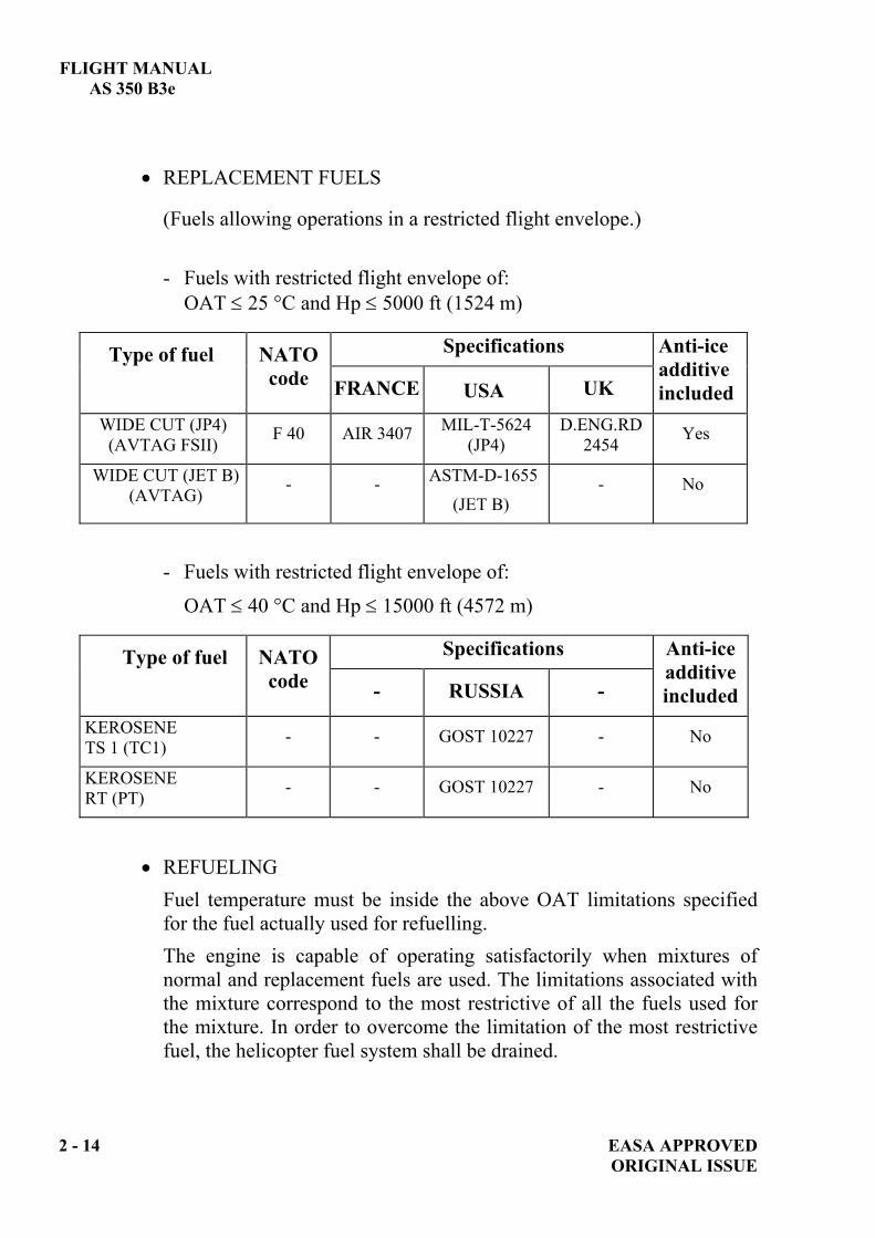
REPLACEMENT FUELS
(Fuels allowing operations in a restricted flight envelope.)
- Fuels with restricted flight envelope of: OAT 25 °C and Hp 5000 ft (1524 m)
Specifications Type of fuel NATO code FRANCE USA UK
Anti-ice additive included
WIDE CUT (JP4) (AVTAG FSII) F 40 AIR 3407 MIL-T-5624
(JP4) D.ENG.RD
2454 Yes
WIDE CUT (JET B) (AVTAG) - - ASTM-D-1655
(JET B) - No
- Fuels with restricted flight envelope of:
OAT 40 °C and Hp 15000 ft (4572 m)
Specifications Type of fuel NATO code - RUSSIA -
Anti-ice additive included
KEROSENE TS 1 (TC1) - - GOST 10227 - No
KEROSENE RT (PT) - - GOST 10227 - No
REFUELING Fuel temperature must be inside the above OAT limitations specified for the fuel actually used for refuelling. The engine is capable of operating satisfactorily when mixtures of normal and replacement fuels are used. The limitations associated with the mixture correspond to the most restrictive of all the fuels used for the mixture. In order to overcome the limitation of the most restrictive fuel, the helicopter fuel system shall be drained.
FLIGHT MANUALAS 350 B3e
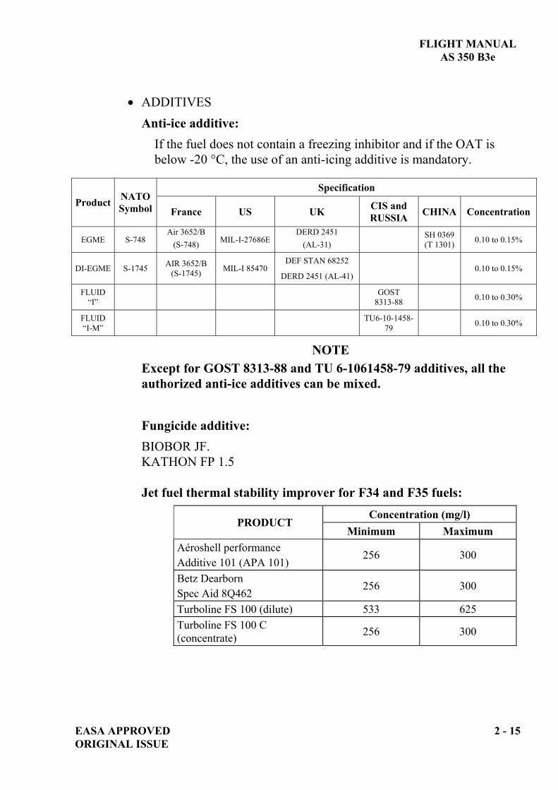
ADDITIVESAnti-ice additive:
If the fuel does not contain a freezing inhibitor and if the OAT is below -20 °C, the use of an anti-icing additive is mandatory.
SpecificationProduct NATO
Symbol France US UK CIS and RUSSIA CHINA Concentration
EGME S-748Air 3652/B
(S-748) MIL-I-27686EDERD 2451
(AL-31)SH 0369 (T 1301) 0.10 to 0.15%
DI-EGME S-1745 AIR 3652/B (S-1745) MIL-I 85470
DEF STAN 68252
DERD 2451 (AL-41) 0.10 to 0.15%
FLUID“I”
GOST8313-88 0.10 to 0.30%
FLUID“I-M”
TU6-10-1458-79 0.10 to 0.30%
NOTEExcept for GOST 8313-88 and TU 6-1061458-79 additives, all the authorized anti-ice additives can be mixed.
Fungicide additive:BIOBOR JF.
KATHON FP 1.5
Jet fuel thermal stability improver for F34 and F35 fuels: Concentration (mg/l)
PRODUCTMinimum Maximum
Aéroshell performance Additive 101 (APA 101)
256 300
Betz Dearborn Spec Aid 8Q462
256 300
Turboline FS 100 (dilute) 533 625Turboline FS 100 C (concentrate) 256 300
EASA APPROVED 2 - 15 ORIGINAL ISSUE

FLIGHT MANUAL AS 350 B3e
2.5.2 APPROVED LUBRICANTS AND FLUIDS ENGINE LUBRICANTS
NORMAL USE (forbidden for OAT < -30°C)SpecificationOil type NATO
Code FRANCE USA UKClass Approved oil trademarks
Recommended use
Average synthetic 5 cSt at 98.9° C
0.156 -
MIL-PRF-23699
orMIL-L-23699
DEFSTAN91-101
HTS(High
thermal stability)
BP (EXXON) Turbo Oil 2197 MOBIL Jet Oil 254
(Corrosioninhibiting) CASTROL Aerojet 5 Normal use
Average synthetic
5 cSt at 98.9° C
0.156 -MIL-PRF-
23699 or
MIL-L-23699
DEFSTAN91-101
StandardCASTROL 5000 Aero SHELL Turbine Oil 500 MOBIL Jet Oil 2 TURBO NYCOIL 600 TOTAL Aero Turbine 535 ELF TURBO Jet IITOTAL PRESLIA SE jet
OTHER OILS (forbidden for OAT > 30°C) SpecificationOil type NATO
Code FRANCE USA UKClass Approved oil trademarks
0.148 -MIL-L-7808MIL-PRF-
7808- -
CASTROL 325 CASTROL 3C BP (EXXON) Turbo Oil 2389 MOBIL AVREX 256 TURBO NYCOIL 160
Synthetic fluid
3 to 3.5 cSt at 98.9° C 0.150 AIR 3514 - - - TURBO NYCOIL 13B
ELF Jet Synthetic Oil 15
Synthetic fluid 3.9 cSt at 98.9° C - - -
DEFSTAN91-94
- Aero SHELL Turbine Oil 390
NOTE 1 When the oil specification/grade/ trademark differs from the approved one, TURBOMECA approval shall be obtained before using this oil.
NOTE 2 In case of oil change with trademark/ NATO code/ category/ grade or specification change, apply instructions as prescribed in the TURBOMECA Maintenance Manual.
NOTE 3 All specifications are effective at latest issue or amendment.
2 - 16 EASA APPROVED ORIGINAL ISSUE
FLIGHT MANUAL AS 350 B3e
EASA APPROVED 2 - 17 ORIGINAL ISSUE
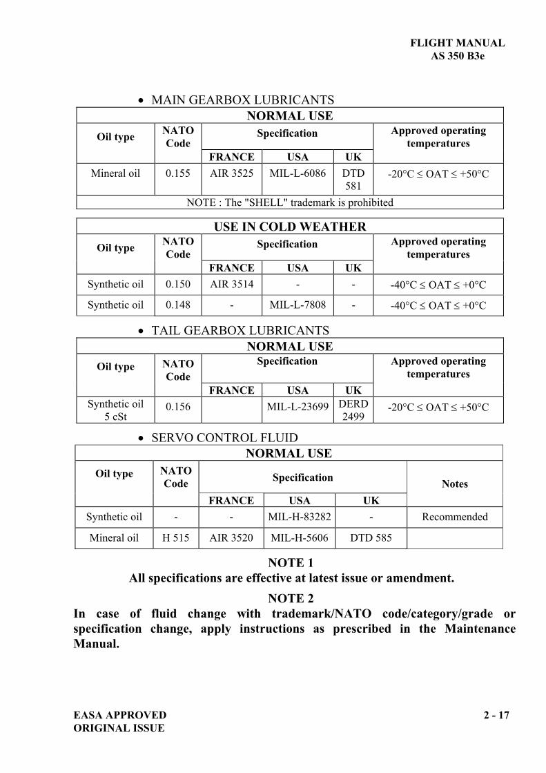
MAIN GEARBOX LUBRICANTS NORMAL USE
Oil type NATO Code
Specification Approved operating temperatures
FRANCE USA UK Mineral oil 0.155 AIR 3525 MIL-L-6086 DTD
581 -20°C OAT +50°C
NOTE : The "SHELL" trademark is prohibited
USE IN COLD WEATHER Oil type NATO
Code Specification Approved operating
temperatures FRANCE USA UK
Synthetic oil 0.150 AIR 3514 - - -40°C OAT +0°C
Synthetic oil 0.148 - MIL-L-7808 - -40°C OAT +0°C
TAIL GEARBOX LUBRICANTS NORMAL USE
Oil type NATO Code
Specification Approved operating temperatures
FRANCE USA UK Synthetic oil
5 cSt 0.156 MIL-L-23699 DERD
2499 -20°C OAT +50°C
SERVO CONTROL FLUID NORMAL USE
Oil type NATO Code Specification
FRANCE USA UK Notes
Synthetic oil - - MIL-H-83282 - Recommended
Mineral oil H 515 AIR 3520 MIL-H-5606 DTD 585
NOTE 1 All specifications are effective at latest issue or amendment.
NOTE 2 In case of fluid change with trademark/NATO code/category/grade or specification change, apply instructions as prescribed in the Maintenance Manual.

FLIGHT MANUAL AS 350 B3e
2 - 18 EASA APPROVED ORIGINAL ISSUE
2.5.3 BAGGAGE COMPARTMENT LOAD LIMITATIONS RH cargo compartment...........................: 100 kg (220 lb) LH cargo compartment ...........................: 120 kg (264 lb) with a max. distributed load of 300 kg/m2 (62.5 lb/ft2) Rear cargo compartment.........................: 80 kg (176 lb) with a max. distributed load of 145 kg/m2 (30 lb/ft2)
2.5.4 CABIN COMPARTMENT LOAD LIMITATIONS Rear cabin floor.......................................: 310 kg (682 lb) Forward left cabin floor ..........................: 150 kg (330 lb) with a max. distributed load of 300 kg/m2 (62.5 lb/ft2)
2.5.5 MANDATORY EQUIPMENT A minimum of two adequate radio / audio headsets shall be on-board the helicopter, one worn by the pilot at the controls to monitor the audio warning delivered through the ICS system, and a spare one.
2.5.6 OPTIONAL EQUIPMENT When optional equipments are installed, refer to supplements for additional limitations, procedures and performance data.
FLIGHT MANUAL AS 350 B3e
EASA APPROVED 2 - 19 ORIGINAL ISSUE
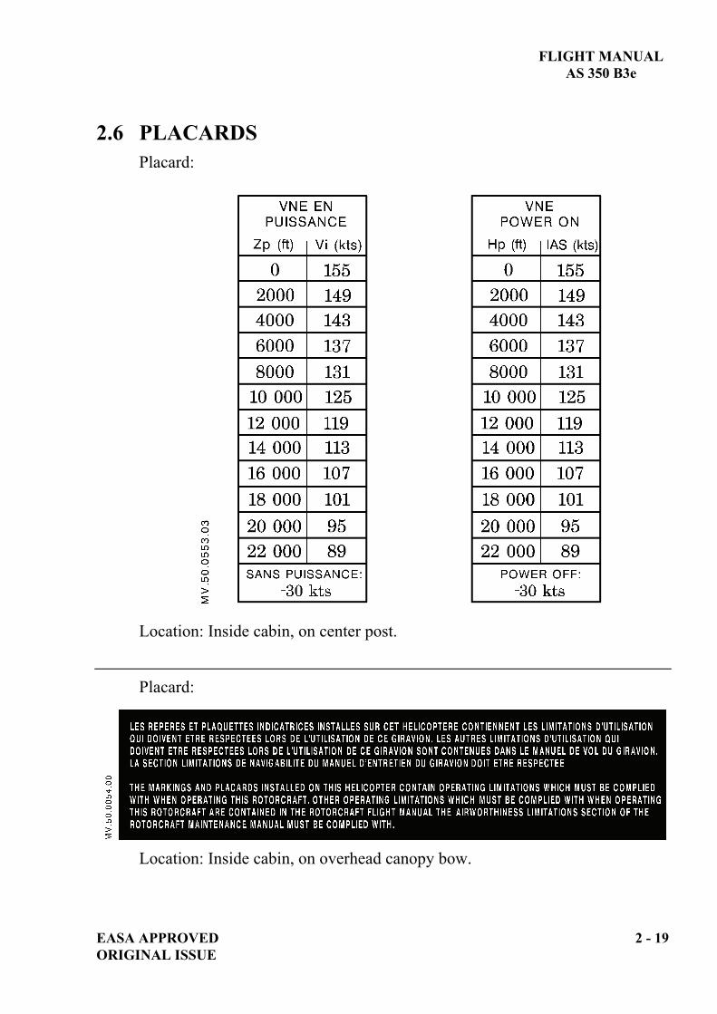
2.6 PLACARDS Placard:
Location: Inside cabin, on center post.
Placard:
Location: Inside cabin, on overhead canopy bow.

FLIGHT MANUAL AS 350 B3e
2 - 20 EASA APPROVED ORIGINAL ISSUE
Placard:
- LH side - RH side.
Location: Inside cabin, at bottom of doors.
Placard:
Location: Console RH side.

FLIGHT MANUAL AS 350 B3e
EASA APPROVED 2 - 21 ORIGINAL ISSUE
Placard:
Location: Inside cabin, on center post.
Placard:
Location: on console.
Placard:
Location: Cargo hold LH side Location: Cargo hold RH side
Placard:
Location: Rear cargo hold
FLIGHT MANUAL AS 350 B3e
2 - 22 EASA APPROVED ORIGINAL ISSUE
Placard:
Location: Near filler neck, LH side.
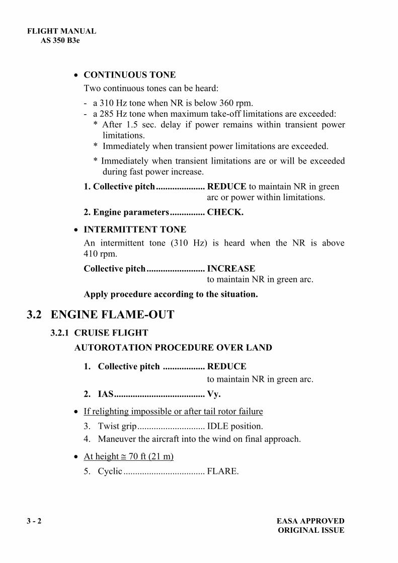
Placard:
Location: Near filler neck, LH side.
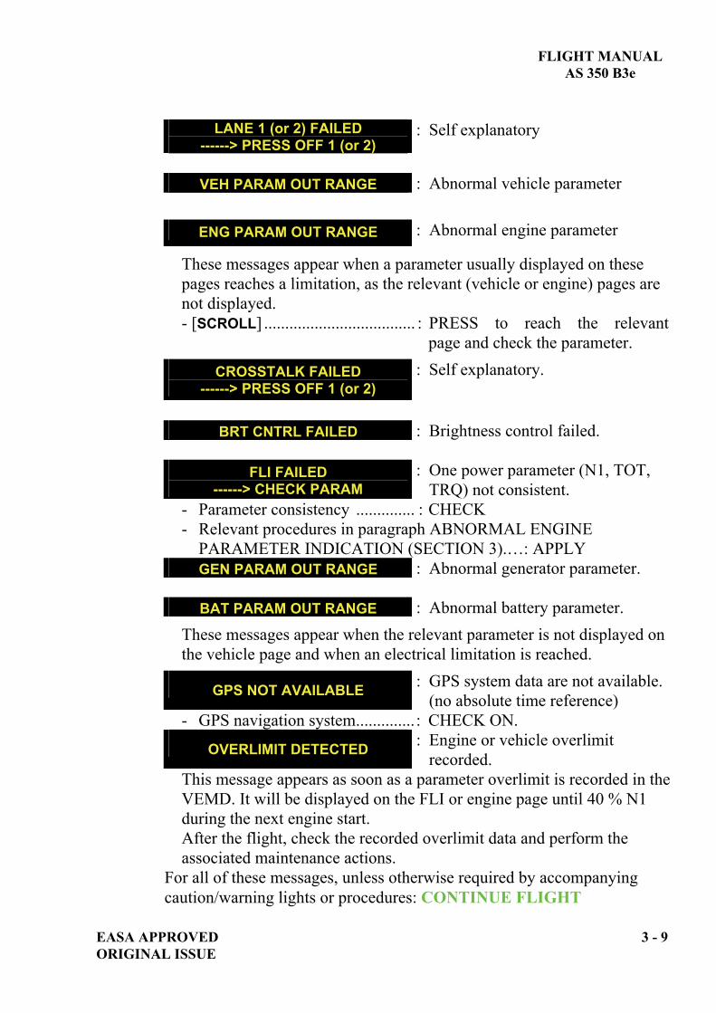
Placard:
Location: RH side, on ground power receptacle cover.

FLIGHT MANUAL AS 350 B3e
EASA APPROVED 3 - i ORIGINAL ISSUE
SECTION 3 EMERGENCY PROCEDURES
Page 3.1 GENERAL.....................................................................................................3-1
3.1.1 AUDIO WARNINGS .........................................................................3-1 3.2 ENGINE FLAME-OUT...............................................................................3-2
3.2.1 CRUISE FLIGHT ..............................................................................3-2 3.2.2 HOVER-IGE.......................................................................................3-4 3.2.3 HOVER-OGE .....................................................................................3-4 3.2.4 IN FLIGHT RELIGHTING..............................................................3-4
3.3 TAIL ROTOR FAILURES..........................................................................3-5 3.3.1 COMPLETE LOSS OF TAIL ROTOR EFFECTIVENESS.........3-5 3.3.2 TAIL ROTOR CONTROL FAILURE ............................................3-6
3.4 SMOKE IN THE COCKPIT/CARGO.......................................................3-7 3.4.1 SOURCE NOT IDENTIFIED...........................................................3-7 3.4.2 SOURCE IDENTIFIED.....................................................................3-7
3.5 VEMD FAILURE .........................................................................................3-8 3.5.1 VEMD SCREEN FAILURE..............................................................3-8 3.5.2 CAUTION MESSAGES ON VEMD ................................................3-8 3.5.3 ABNORMAL NR/N2 INDICATION..............................................3-10 3.5.4 ABNORMAL ENGINE PARAMETER INDICATION...............3-11
3.6 CAUTION AND WARNING PANEL......................................................3-13 3.6.1 ENGINE EMERGENCY.................................................................3-13 3.6.2 TRANSMISSION EMERGENCY..................................................3-17 3.6.3 HYDRAULIC EMERGENCY........................................................3-18 3.6.4 ELECTRICAL EMERGENCY ......................................................3-19 3.6.5 FUEL EMERGENCY......................................................................3-21 3.6.6 MISCELLANEOUS.........................................................................3-23

FLIGHT MANUAL AS 350 B3e
3 - ii EASA APPROVED ORIGINAL ISSUE
Page
3.7 VARIOUS WARNINGS, FAILURES AND INCIDENTS NOT INDICATED ON THE CWP................................................................ 3-24 3.7.1 ROTOR BRAKE INOPERATIVE ...................................................... 3-24 3.7.2 HYDRAULIC SYSTEM FAILURES.................................................. 3-24 3.7.3 BLEED VALVE FAILURE.................................................................. 3-25 3.7.4 ICS INOPERATIVE (GMA 340 H)..................................................... 3-26

FLIGHT MANUAL AS 350 B3e
EASA APPROVED 3 - 1 ORIGINAL ISSUE
3.1 GENERAL Emergency procedures describe the actions that the pilot must take relative to the various possible failures that can occur. Meanwhile, depending on the many variable external environments, such as the type of terrain overflown, the pilot may have to adapt to the situation according to his experience. To help the pilot in his decision process, four recommendations are used:
LAND IMMEDIATELY Self explanatory.
LAND AS SOON AS POSSIBLE Emergency conditions are urgent and require landing at the nearest landing site at which a safe landing can be made.
LAND AS SOON AS PRACTICABLE Emergency conditions are less urgent and in the pilot's judgment, he may proceed to the nearest airfield where he can expect appropriate assistance.
CONTINUE FLIGHT Continue flight as planned. Repair at the destination according to the maintenance manual.
NOTE Immediate actions that the pilot shall take are written in bold characters.
3.1.1 AUDIO WARNINGS On the SCU, a HORN] pushbutton is used to activate the audio warning.
When HORN] pushbutton is pressed in: HORN. NOTE
The pilot at the controls shall wear an adequate radio / ICS audio headset to monitor the audio warning through the ICS system. GONG
A gong is generated each time a red warning appears on the warning panel.
FLIGHT MANUAL AS 350 B3e
3 - 2 EASA APPROVED ORIGINAL ISSUE
CONTINUOUS TONE Two continuous tones can be heard: - a 310 Hz tone when NR is below 360 rpm. - a 285 Hz tone when maximum take-off limitations are exceeded:
* After 1.5 sec. delay if power remains within transient power limitations. * Immediately when transient power limitations are exceeded. * Immediately when transient limitations are or will be exceeded during fast power increase.
1. Collective pitch..................... REDUCE to maintain NR in green arc or power within limitations.
2. Engine parameters............... CHECK.
INTERMITTENT TONE An intermittent tone (310 Hz) is heard when the NR is above 410 rpm. Collective pitch......................... INCREASE
to maintain NR in green arc. Apply procedure according to the situation.
3.2 ENGINE FLAME-OUT 3.2.1 CRUISE FLIGHT
AUTOROTATION PROCEDURE OVER LAND
1. Collective pitch .................. REDUCE to maintain NR in green arc.
2. IAS....................................... Vy.
If relighting impossible or after tail rotor failure 3. Twist grip............................. IDLE position. 4. Maneuver the aircraft into the wind on final approach.
At height 70 ft (21 m) 5. Cyclic ................................... FLARE.

FLIGHT MANUAL AS 350 B3e
EASA APPROVED 3 - 3 ORIGINAL ISSUE
At 20/25 ft (6/8 m) and at constant attitude
6. Collective pitch ....................GRADUALLY INCREASE to reduce the rate of descent and forward speed
7. Cyclic ...................................FORWARD to adopt a slightly nose-up landing attitude (< 10°).
8. Pedal .....................................ADJUST to cancel any sideslip tendency.
9. Collective pitch .................... INCREASE to cushion touch-down.
After touch-down 10. Cyclic, collective, pedal .......ADJUST to control ground run.
Once the aircraft has stopped 11. Collective pitch ....................FULL DOWN 12. Rotor brake...........................APPLY below 170 rotor rpm.
AUTOROTATION PROCEDURE OVER WATER Apply same procedure as over land, except items 10, 11 and 12, but maneuver to head the aircraft equally between the wind and wave direction on final approach. Ditch with minimum forward speed (IAS < 30 kt (56 km/h)) and rate of descent. Then apply following check list for items 10, 11, 12.
After touch-down 10. Collective pitch ....................MAINTAIN 11. Door emergency handles......PULL-UP 12. Rotor brake...........................APPLY Abandon aircraft once the rotor has stopped.

FLIGHT MANUAL AS 350 B3e
3 - 4 EASA APPROVED ORIGINAL ISSUE
3.2.2 HOVER-IGE 1. Collective ...............................................MAINTAIN. 2. Pedals .....................................................CONTROL YAW. 3. Collective ...............................................INCREASE as needed to
cushion touch-down. 3.2.3 HOVER-OGE
WARNING SAFE AUTOROTATIVE LANDING CAN NOT BE ASSURED IN CASE OF A FAILURE IN HOGE BELOW THE TOP POINT OF THE HV DIAGRAM (REFER TO SECTION 5) OR IN CONFINED AREA.
1. Collective pitch................................FULL DOWN.
When NR stops decreasing
2. Cyclic................................................FORWARD to gain airspeed according to
available height. 3. Autorotation procedure.....................APPLY.
3.2.4 IN FLIGHT RELIGHTING According to available height and cause of flame-out:
1. Starting selector ..............................OFF position. 2. GENE ..............................................OFF. 3. FUEL P ............................................ON. 4. Starting selector ..............................ON position.
The relighting sequence will therefore be automatically carried out as soon as N1 < 10 %.
After relighting
5. GENE ..............................................ON. 6. FUEL P ............................................OFF.
At least 1000 ft (300 m) are necessary to complete relighting procedure after flame-out.

FLIGHT MANUAL AS 350 B3e
EASA APPROVED 3 - 5 ORIGINAL ISSUE
3.3 TAIL ROTOR FAILURES 3.3.1 COMPLETE LOSS OF TAIL ROTOR EFFECTIVENESS
Symptom: the helicopter will yaw to the left with a rotational speed depending on the amount of power and the forward speed set at the time of the failure.
WARNING SAFE AUTOROTATIVE LANDING CAN NOT BE ASSURED IN CASE OF A FAILURE IN HOGE BELOW THE TOP POINT OF THE HV DIAGRAM (REFER TO SECTION 5) OR IN CONFINED AREA.
3.3.1.1 HOVER-IGE (or OGE in HV diagram)
LAND IMMEDIATELY 1. Twist Grip ...........................IDLE position. 2. Collective ............................INCREASE to cushion touch-down.
3.3.1.2 HOVER-OGE (Clear area, out of HV diagram) Simultaneously, 1. Collective ............................REDUCE depending on available
height. 2. Cyclic ...................................FORWARD to gain speed. 3. Cyclic ...................................ADJUST to set IAS to Vy and
control yaw.
LAND AS SOON AS POSSIBLE
If a go-around has been performed, carry out an autorotative landing on an area suitable for the autorotation procedure.
3.3.1.3 IN CRUISE FLIGHT 1. Cyclic ..................................ADJUST to set IAS to Vy and
control yaw. 2. Collective .............................REDUCE to avoid sideslip.
LAND AS SOON AS POSSIBLE

FLIGHT MANUAL AS 350 B3e
3 - 6 EASA APPROVED ORIGINAL ISSUE
APPROACH AND LANDING On a suitable area for autorotative landing: 1. Twist grip ............................ IDLE position. 2. Carry out an autorotative landing according to the autorotation
procedure (Refer to paragraph 3.2.1).
3.3.2 TAIL ROTOR CONTROL FAILURE
Symptom: jamming of pedals or loss of pedal effectiveness. These conditions make it impossible to change tail rotor thrust with the pedals.
WARNING LANDING IS MADE EASIER BY LANDING WITH A RH WIND COMPONENT. WHEN AIRSPEED IS LESS THAN 20 KT (37 KM/H), GO-AROUND IS IMPOSSIBLE DUE TO LOSS OF VERTICAL FIN EFFICIENCY.
1. Cyclic and collective................ ADJUST to set IAS to 70 kt (130 km/h) in level flight.
On a suitable area for a running landing procedure: Make a shallow approach with a slight left sideslip. Perform a running landing, the sideslip will be reduced progressively as airspeed is reduced and collective is applied to cushion the landing.

FLIGHT MANUAL AS 350 B3e
EASA APPROVED 3 - 7 ORIGINAL ISSUE
3.4 SMOKE IN THE COCKPIT/CARGO 3.4.1 SOURCE NOT IDENTIFIED
Heating, Demisting .......................OFF smoke clears
YES NO CONTINUE FLIGHT
depending on weather conditions If DC parameters not correct: 12. [GENE] ............................. OFF. 13. Unnecessary equipment ... OFF.
LAND AS SOON AS PRACTICABLE
1. [EMER SW] .........................................SHUT OFF. 2. [DCT/BAT]...........................................OFF. 3. [BAT/EPU]...........................................OFF. 4. [GENE] ................................................OFF. 5. [AVIONIC]............................................OFF. 6. Ventilate the cabin.
When smoke clears: 7. All consumers .....................................OFF. 8. [EMER SW]..........................................ON. 9. [DCT/BAT]...........................................ON check DC
Parameters. 10. [BAT/EPU]...........................................ON check DC Parameters. 11. [GENE] ................................................ON check DC Parameters.
If DC parameters correct and no smoke detected: 12. [AVIONIC]............................................ON. 13. All consumers .....................................ON, one by
one to identify the failed system; then keep it off.
CAUTION When [EMER SW] is actuated or battery and generator are off line, the VEMD goes off and only the analogue NR indication remains on. Apply the procedure for failure of both screens (§ 3.5.1 VEMD SCREEN FAILURE Section 3).
3.4.2 SOURCE IDENTIFIED 1. Corresponding system..............OFF. 2. Ventilate the cabin.
CONTINUE FLIGHT depending on system failed.
NOTE After DC had been switched-off and on in flight, GOV light will remain on until the next normal full engine and battery switch-off on the ground. NR is constant at 394 rpm.

FLIGHT MANUAL AS 350 B3e
3 - 8 EASA APPROVED ORIGINAL ISSUE
3.5 VEMD FAILURE 3.5.1 VEMD SCREEN FAILURE
Failure of one screen [OFF1] or [OFF2] ....................... OFF. Read all available information on the other screen. Information is available using the [SCROLL] pushbutton either on the VEMD or on the collective pitch lever. If top screen fails, the 3-parameters engine page will be automatically displayed on lower screen.
Failure of both screens Can be a single failure when [EMER SW] or battery push buttons and DC generator are in "OFF" position (fire and smoke detection procedure). In this case, to avoid any power overlimit, the maximum authorized power will be the power needed to establish level flight with the following law:
IAS kt = 100 kt at 0 Hp - (2 kt / 1000 ft). IAS km/h = 185 km/h at 0 Hp - (4 km/h per 300 m).
LAND AS SOON AS PRACTICABLE Landing procedure: carry out a no hover landing. NR is constant at 394 rpm.
3.5.2 CAUTION MESSAGES ON VEMD
When a parameter is off line, the parameter value is not displayed on the corresponding VEMD screen and the parameter scale symbology is displayed in yellow. Caution messages are self explanatory and the pilot shall comply with the action requested. If no light is lit on the caution and warning panel, no other action is required from the pilot.
FLIGHT MANUAL AS 350 B3e
EASA APPROVED 3 - 9 ORIGINAL ISSUE
LANE 1 (or 2) FAILED ------> PRESS OFF 1 (or 2)
: Self explanatory
VEH PARAM OUT RANGE : Abnormal vehicle parameter
ENG PARAM OUT RANGE : Abnormal engine parameter
These messages appear when a parameter usually displayed on these pages reaches a limitation, as the relevant (vehicle or engine) pages are not displayed. - [SCROLL] .................................... : PRESS to reach the relevant
page and check the parameter.
CROSSTALK FAILED ------> PRESS OFF 1 (or 2)
: Self explanatory.
BRT CNTRL FAILED : Brightness control failed.
FLI FAILED
------> CHECK PARAM : One power parameter (N1, TOT, TRQ) not consistent.
- Parameter consistency .............. : CHECK - Relevant procedures in paragraph ABNORMAL ENGINE
PARAMETER INDICATION (SECTION 3).…: APPLY GEN PARAM OUT RANGE : Abnormal generator parameter.
BAT PARAM OUT RANGE : Abnormal battery parameter.
These messages appear when the relevant parameter is not displayed on the vehicle page and when an electrical limitation is reached.
GPS NOT AVAILABLE : GPS system data are not available. (no absolute time reference)
- GPS navigation system.............. : CHECK ON.
OVERLIMIT DETECTED : Engine or vehicle overlimit recorded.
This message appears as soon as a parameter overlimit is recorded in the VEMD. It will be displayed on the FLI or engine page until 40 % N1 during the next engine start. After the flight, check the recorded overlimit data and perform the associated maintenance actions.
For all of these messages, unless otherwise required by accompanying caution/warning lights or procedures: CONTINUE FLIGHT
FLIGHT MANUAL AS 350 B3e
3 - 10 EASA APPROVED ORIGINAL ISSUE
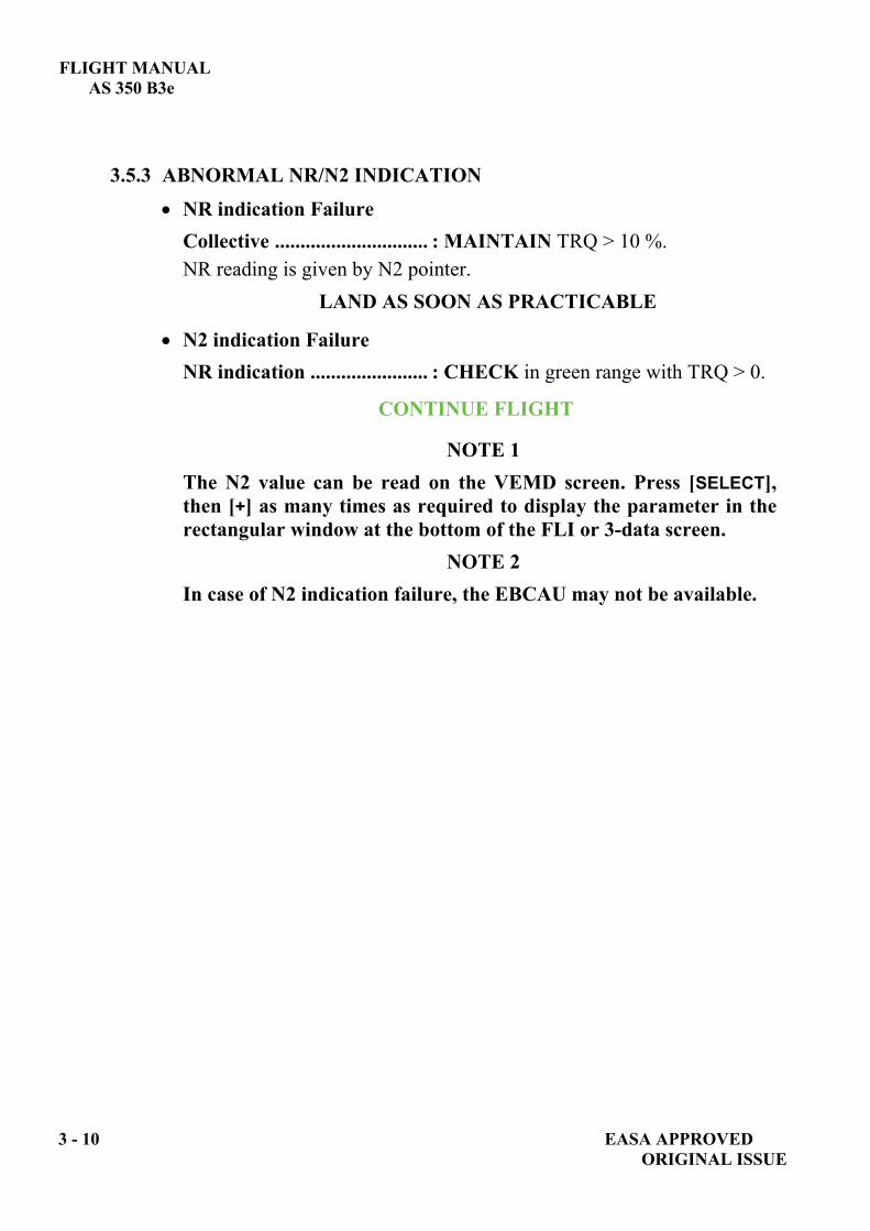
3.5.3 ABNORMAL NR/N2 INDICATION
NR indication Failure Collective .............................. : MAINTAIN TRQ > 10 %. NR reading is given by N2 pointer.
LAND AS SOON AS PRACTICABLE
N2 indication Failure NR indication ....................... : CHECK in green range with TRQ > 0.
CONTINUE FLIGHT
NOTE 1 The N2 value can be read on the VEMD screen. Press [SELECT], then [+] as many times as required to display the parameter in the rectangular window at the bottom of the FLI or 3-data screen.
NOTE 2 In case of N2 indication failure, the EBCAU may not be available.

FLIGHT MANUAL AS 350 B3e
EASA APPROVED 3 - 11 ORIGINAL ISSUE
3.5.4 ABNORMAL ENGINE PARAMETER INDICATION Engine Oil Temperature over limit
Airspeed ....................................SET to 80 KIAS (148 km/h)
Temperature decreases,
YES
NO
LAND AS SOON AS PRACTICABLE LAND AS SOON AS POSSIBLE Check cooler fan operation
Low Engine Oil Pressure
- CWP ...............................................CHECK ENG P
NO YES
CWP light test...................... COMPLETED
ENG P ENG P LAND IMMEDIATELY - Autorotation procedure ....APPLY. LAND AS SOON AS - Shutdown engine time permitting. PRACTICABLE

FLIGHT MANUAL AS 350 B3e
3 - 12 EASA APPROVED ORIGINAL ISSUE
Loss of N1, TRQ or TOT parameters When a parameter is off line, the parameter value is not displayed on the VEMD upper screen and the parameter scale symbology is displayed in yellow. The First Limitation Indicator (FLI) is replaced by the 3 data symbology (N1/ N1, TOT and TRQ) and a failure message is displayed. - N1/ N1 Indicator Failure:
Comply with the maximum TRQ value and TOT limit of 842°C. NOTE
In this case, the TOT limitations displayed are the starting limitations.
- Torquemeter Failure: Comply with the N1 given in the following table:
23
N1= - 4
12 95 96 10
93 94 96 97 8
91 93 94 96 97 6
90 91 93 94 96 97 4
88 90 91 93 94 96 97 2
Hp
(ft x
100
0)
087 89 90 92 93 95 96 97
-40 -30 -20 -10 0 10 20 30 40 50
OAT (°C)
- N1 and Torquemeter indications failure:
warning can also induce loss of N1 and TRQ indications. The VEMD switches to 3-data symbology with only TOT and numeric N1 as valid parameter. Comply with N1 limitations in the above table, substituting the N1 = - 4 limit by a TOT limit of 842°C.
- TOT Indicator Failure: Comply with N1 and TRQ limitations. Switch off heating and demisting system. On ground: do not try to start the engine.
For all these failures: LAND AS SOON AS PRACTICABLE
GOV

FLIGHT MANUAL AS 350 B3e
EASA APPROVED 3 - 13 ORIGINAL ISSUE
3.6 CAUTION AND WARNING PANEL 3.6.1 ENGINE EMERGENCY
WARNING PANEL CORRECTIVE ACTIONS
Fire in engine bay.
At start-up : 1. Starting selector.................................. OFF position. 2. Emergency fuel
shut-off handle.................................... AFT. 3. [FUEL P] ............................................... OFF. 4. CRANK ............................................... PRESS (10 sec.). 5. [EMER SW] ........................................... OFF. 6. Rotor brake ........................................... APPLY ( 170 rpm). 7. Evacuate aircraft and fight fire from outside.
Hover, Takeoff, Final:
LAND IMMEDIATELY Carry out a no hover, powered landing then, once on ground, apply same procedure as above.
In Flight:
LAND IMMEDIATELY 1. Collective pitch ................................... LOWER. 2. IAS ....................................................... Vy. 3. Autorotation procedure ..................... APPLY. 4. Emergency fuel shut-off handle........ AFT. 5. Starting selector.................................. OFF position.
After landing: 6. [EMER SW] ........................................... OFF. 7. Rotor brake ........................................... APPLY ( 170 rpm). 8. Evacuate aircraft and fight fire from outside.
ENG FIRE

FLIGHT MANUAL AS 350 B3e
3 - 14 EASA APPROVED ORIGINAL ISSUE
WARNING PANEL CORRECTIVE ACTIONS
Major governor
failure
Emergency mode engaged
IN FLIGHT: 1. Flight parameters........... CHECK
Emergency mode automatically self-engages. illuminates.
2. Collective pitch............... AVOID abrupt changes Maintain N1 > 80% Hp < 20000 ft (6096 m)
Maintain N1 > 85% Hp 20000 ft (6096 m) LAND AS SOON AS PRACTICABLE
Approach and Landing: . Make a powered approach. . Avoid steep angle.
After touch down, shut-down: Collective pitch.................. SLOWLY down to low pitch. Starting selector ................. OFF.
NOTE On FLI page: FF and END .
This failure can also result in loss of N1 and torque parameters on the VEMD.
DURING ENGINE STARTING: Starting selector ................... OFF position immediately.
GOV
GOV

FLIGHT MANUAL AS 350 B3e
EASA APPROVED 3 - 15 ORIGINAL ISSUE
WARNING
PANEL CORRECTIVE ACTIONS
Minor FADEC failure
Permanently lighted: Governing function degraded.
1. Collective......................AVOID abrupt power changes. 2. IAS................................MAINTAIN below VNE power off.
LAND AS SOON AS PRACTICABLE On ground: do not start engine.
Flashing at idle or during starting or shut down: Governor redundancy failure, no impact on governing
function. . Start-up procedure: abort, report to Maintenance Manual. . Autorotation training: cancel training, return to base.
Engine oil pressure
below limit.
Oil pressure........................CHECK gauge.
LOW OR NIL NORMAL
LAND IMMEDIATELY LAND AS SOON AS PRACTICABLE
. Autorotation procedure … APPLY.
. Shutdown engine time permitting.
Twist grip out of FLIGHT position
Twist grip ...........................TURN to FLIGHT position.
CONTINUE FLIGHT
GOV
ENG P
TWT GRIP

FLIGHT MANUAL AS 350 B3e
3 - 16 EASA APPROVED ORIGINAL ISSUE
WARNING PANEL CORRECTIVE ACTIONS
Metal particles in engine oil circuit.
Collective pitch................... REDUCE power
LAND AS SOON AS POSSIBLE
Low power approach and landing Be prepared in case of a loss of engine power.
NOTE Takeoff is prohibited until checks specified in TURBOMECA Maintenance Manual have been completed.
ENG CHIP

FLIGHT MANUAL
AS 350 B3e
3.6.2 TRANSMISSION EMERGENCY
WARNINGPANEL CORRECTIVE ACTIONS
Main Gear Box low oil pressure
< 1 bar (14.5 psi)
Collective ............................REDUCE power
LAND AS SOON AS POSSIBLE If a safe landing is not possible, continue flight to the nearest appropriate landing site, reduce power to fly at minimum power speed (Vy).
NOTEAt low power (Vy) a maximum of 55 min. of simulated flight time has been demonstrated during bench tests
Main Gear Box oil overheating
(> 115°C)
IAS .......................................SET TO Vy CWP.....................................MONITOR
LAND AS SOON AS PRACTICABLE
LAND AS SOON AS POSSIBLE
Metal particles in MGB oil circuit.
Collective .............................REDUCE power
and ..................MONITOR
LAND AS SOON AS POSSIBLE
Metal particles in TGB oil circuit.
Avoid prolonged hovering
CONTINUE FLIGHT
MGBP
MGBTEMP
MGBTEMP
MGBTEMP
MGBTEMP
MGBP
MGBCHIP
TGBCHIP
EASA APPROVED 3 - 17 ORIGINAL ISSUE

FLIGHT MANUAL AS 350 B3e
3 - 18 EASA APPROVED ORIGINAL ISSUE
3.6.3 HYDRAULIC EMERGENCY WARNING
PANEL CORRECTIVE ACTIONS
Loss of hydraulic
pressure
or
pressure < 30 bar (435 psi).
Keep aircraft at a more or less level attitude. Avoid abrupt maneuvers.
CAUTION Pedal control loads increase notably, in particular at high pedal deflections. Do not attempt to carry out hover flight or any low speed maneuver. The intensity and direction of the control feedback force will change rapidly. This will result in poor aircraft control and possible loss of control. As control loads increase, be careful not to inadvertently move twist grip out of FLIGHT position (TWT GRIP light off).
NOTE
The pressure in the accumulators allows enough time to secure flight and to reach the hydraulic failure safety speed.
In hover: 1. Land normally 2. Twist grip................................. Set to IDLE position. 3. Collective................................. LOCK. 4. Starting selector ....................... OFF. In flight: Smoothly, 1. Collective/Cyclic..................... SET IAS to between 40 (74 Km/h) and 60 kt (111 Km/h).
(hydraulic failure safety speed). 2. Collective HYD switch............ OFF.
Pilot has to apply loads: - on collective increase or decrease around no force feedback point, - on forward and left cyclic.
LAND AS SOON AS POSSIBLE
NOTE Speed may be increased as necessary but control loads will increase with speed. Approach and landing: over a clear and flat area, - perform a flat approach into wind, - make a no-hover slow running landing around 10 kt (18.5 km/h), - Do not hover or taxi without hydraulic pressure.
After landing: - Collective .................................. LOCK. - Shutdown procedure.................. Apply.
HYDR

FLIGHT MANUAL AS 350 B3e
EASA APPROVED 3 - 19 ORIGINAL ISSUE
3.6.4 ELECTRICAL EMERGENCY
WARNING PANEL CORRECTIVE ACTIONS
Battery temperature above
maximum.
1 [BAT/EPU] ..............................................................OFF. 2.U bus voltage..........................................................CHECK.
NORMAL ABOVE Umax 1. [BAT/EPU] ..................ON. 2. [GENE]........................OFF. 3. Unnecessary equipment ...................OFF. LAND AS SOON AS PRACTICABLE
Battery off line.
[BAT/EPU] .......................................................CHECK ON. YES NO [BAT/EPU] ..............ON.
CHECK voltage on VEMD. LAND AS SOON AS
PRACTICABLE CONTINUE FLIGHT
BATT TEMP
BATT
BATT

FLIGHT MANUAL AS 350 B3e
3 - 20 EASA APPROVED ORIGINAL ISSUE
WARNING PANEL CORRECTIVE ACTIONS
DC generator off line.
1. U bus on VEMD ............ CHECK. 2. [GENE] ............................. CHECK ON. YES NO [GENE] .......................... ON. "GENE RST" circuit breaker ....................Check not popped out (30 panel). [GENE RST]..............................................PRESS, Unnecessary equipment ....... OFF.
CONTINUE FLIGHT LAND AS SOON AS PRACTICABLE
CAUTION If the battery fails, the VEMD will go out and only the analogue NR indication will remain. Maximum flight time on battery: . day : 50 min. (1 VHF, 1 VOR). . night : 20 min. (same as day plus
instrument lighting and external lights).
AC power supply failure
Inverter* AC system: [INV] ............................................................CHECK ON
YES NO Loss of all AC consumers [INV] ................................ ON
NOTE AFCS* disengages automatically INV Controls.............. HANDS ON.
CONTINUE FLIGHT CONTINUE FLIGHT (*) If installed
GENE
GENE GENE
INV

FLIGHT MANUAL
AS 350 B3e
3.6.5 FUEL EMERGENCY
WARNINGPANEL CORRECTIVE ACTIONS
Fuel quantity 48 kg (106 lb)
LAND AS SOON AS POSSIBLE NOTE
15 min. of flight time remains at MCP
WARNING
AVOID LARGE ATTITUDE CHANGES
Low fuel pressure
IN FLIGHT: 1. Collective pitch...................... REDUCE POWER 2. [FUEL P] ................................. ON
LAND AS SOON AS POSSIBLE
. Low power approach and landing
WARNING
BE PREPARED IN CASE OF AN ENGINEFLAME-OUT.
FUEL
FUEL P
EASA APPROVED 3 - 21 ORIGINAL ISSUE
FLIGHT MANUAL AS350 B3e
3 - 22 EASA APPROVEDORIGINAL ISSUE
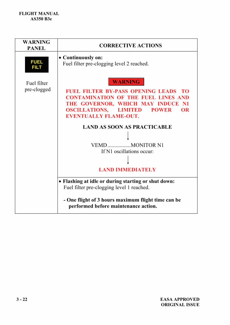
WARNING PANEL CORRECTIVE ACTIONS
Fuel filter pre-clogged
Continuously on: Fuel filter pre-clogging level 2 reached.
WARNING
FUEL FILTER BY-PASS OPENING LEADS TO CONTAMINATION OF THE FUEL LINES AND THE GOVERNOR, WHICH MAY INDUCE N1 OSCILLATIONS, LIMITED POWER OR EVENTUALLY FLAME-OUT.
LAND AS SOON AS PRACTICABLE
VEMD .................MONITOR N1
If N1 oscillations occur:
LAND IMMEDIATELY
Flashing at idle or during starting or shut down: Fuel filter pre-clogging level 1 reached.
- One flight of 3 hours maximum flight time can be
performed before maintenance action.
FUEL FILT

FLIGHT MANUAL
AS 350 B3e
3.6.6 MISCELLANEOUS
WARNINGPANEL CORRECTIVE ACTIONS
Pitot heating not operative.
[PITOT] .............................CHECK ON.
YES NO
Monitor airspeed indicator. [PITOT] ...............ON.
CONTINUE FLIGHT
Aural warningnot operative.
[HORN] .............................CHECK ON.
YES NO
Aural warning failure. [HORN] ...............ON.
CONTINUE FLIGHT
One or both cargo hold doors unlocked.
Airspeed...........................REDUCE to 70 kt (130 km/h).
LAND AS SOON AS PRACTICABLE descent and approach at low rate of descent.
PITOT
HORN
DOOR
EASA APPROVED 3 - 23 ORIGINAL ISSUE
FLIGHT MANUAL AS 350 B3e
3 - 24 EASA APPROVED ORIGINAL ISSUE
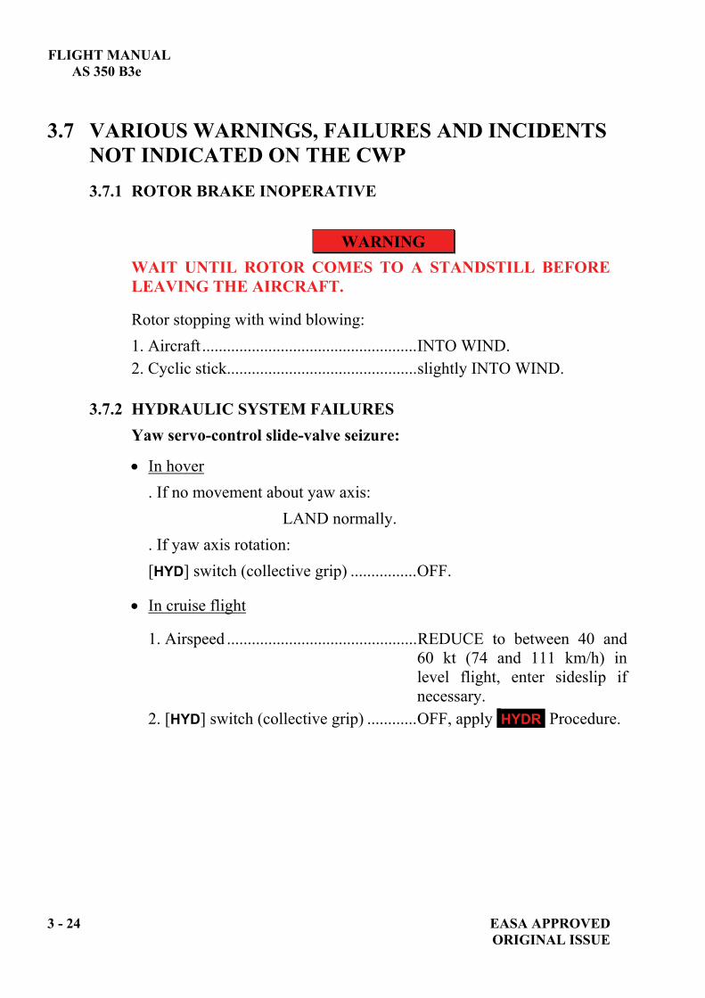
3.7 VARIOUS WARNINGS, FAILURES AND INCIDENTS NOT INDICATED ON THE CWP 3.7.1 ROTOR BRAKE INOPERATIVE
WARNING WAIT UNTIL ROTOR COMES TO A STANDSTILL BEFORE LEAVING THE AIRCRAFT.
Rotor stopping with wind blowing: 1. Aircraft ....................................................INTO WIND. 2. Cyclic stick..............................................slightly INTO WIND.
3.7.2 HYDRAULIC SYSTEM FAILURES Yaw servo-control slide-valve seizure:
In hover . If no movement about yaw axis: LAND normally. . If yaw axis rotation: [HYD] switch (collective grip) ................OFF.
In cruise flight
1. Airspeed ..............................................REDUCE to between 40 and 60 kt (74 and 111 km/h) in level flight, enter sideslip if necessary.
2. [HYD] switch (collective grip) ............OFF, apply HYDR Procedure.

FLIGHT MANUAL AS 350 B3e
EASA APPROVED 3 - 25 ORIGINAL ISSUE
Main servo-control slide-valve seizure:
1. [HYD] switch (collective grip) ..........OFF. Control loads are immediately felt: - on collective increase, - on forward and left cyclic, - on pedals. The aerodynamic loads to be counteracted may be heavy at high speed: - collective pitch : up to 20 daN (45 lbf) to pull, - cyclic : 7 to 12 daN (16 to 27 lbf) to push left, - cyclic : 2 to 4 daN (4.5 to 9 lbf) to push forward.
2. Airspeed............................................REDUCE to between 40 and 60 kt (74 and 111 km/h) in level flight. Apply HYDR procedure.
3.7.3 BLEED VALVE FAILURE:
When the bleed valve opens, a flag appears on the FLI or 3-data page. The flag disappears when the bleed valve closes. The bleed valve is normally open when then the engine is shut down, during starting and at low power settings.
If the flag does not disappear at high power settings (i.e. near MCP or above), the maximum available engine power is reduced, specifically in cold weather.
If the flag does not reappear at low power settings, the engine may surge. Avoid abrupt changes in power settings.
Bleed valve failure results in GOV .
LAND AS SOON AS PRACTICABLE

FLIGHT MANUAL AS 350 B3e
3 - 26 EASA APPROVED ORIGINAL ISSUE
3.7.4 ICS INOPERATIVE (GMA 340 H)*:
1. ICS ..............................................OFF. 2. COM 1 ........................................Check ON, adjust volume.
NOTE 1 VHF communications will remain available for the RH pilot only via COM 1 transceiver. Audio warnings will be transmitted via the COM 1 audio system.
NOTE 2 Abort or cancel hoisting operations in case of ICS failure.
(*) If installed

FLIGHT MANUAL
AS 350 B3e
SECTION 4 NORMAL PROCEDURES
Page 4.1 GENERAL.....................................................................................................4-1
4.1.1 OPERATING LIMITATIONS .........................................................4-1 4.1.2 FLIGHT PLANNING ........................................................................4-1 4.1.3 TAKEOFF AND LANDING DATA.................................................4-1 4.1.4 WEIGHT AND BALANCE DATA ..................................................4-1
4.2 PREFLIGHT CHECK .................................................................................4-2 4.2.1 EXTERIOR CHECK .........................................................................4-2 4.2.2 INTERIOR CHECK ..........................................................................4-5 4.2.3 TURNAROUND CHECK ................................................................4-5
4.3 START UP.....................................................................................................4-6 4.3.1 ENGINE PRESTART CHECK ........................................................4-6 4.3.2 ENGINE STARTING ........................................................................4-8 4.3.3 RUN-UP CHECK ...............................................................................4-9 4.3.4 CRANKING......................................................................................4-11
4.4 TAKEOFF...................................................................................................4-11 4.4.1 BEFORE TAKEOFF CHECK........................................................4-11 4.4.2 TAKEOFF CHECK AND PROCEDURE .....................................4-12
4.5 CLIMB.........................................................................................................4-12
4.6 CRUISE .......................................................................................................4-12
4.7 APPROACH AND LANDING..................................................................4-13 4.7.1 APPROACH .....................................................................................4-13 4.7.2 LANDING .........................................................................................4-13
4.8 ENGINE AND ROTOR SHUTDOWN ....................................................4-13
4.9 MISCELLANEOUS PROCEDURES AND DATA ................................4-14 4.9.1 TANK CAPACITY ..........................................................................4-14
4.10 EXTREME WEATHER OPERATIONS.................................................4-15 4.10.1 HIGH WIND OPERATION (WIND ABOVE 30 KT) .................4-15 4.10.2 COLD WEATHER OPERATION .................................................4-16
EASA APPROVED 4 - i ORIGINAL ISSUE

FLIGHT MANUAL AS 350 B3e
LIST OF FIGURES
Page
FIGURE 4 - 1: SEQUENCE OF CHECKS.........................................................4-2FIGURE 4 - 2: TAKEOFF PROCEDURE........................................................4-12
4 - ii EASA APPROVED ORIGINAL ISSUE
FLIGHT MANUAL AS 350 B3e
EASA APPROVED 4 - 1 ORIGINAL ISSUE
4.1 GENERAL This section contains instructions and procedures for operating the helicopter from the planning stage, through actual flight conditions, to securing the helicopter after landing. Normal and standard conditions are assumed in these procedures. Pertinent data in other sections is referenced when applicable. The instructions and procedures contained herein are written for the purpose of standardization and are not applicable to all situations.
4.1.1 OPERATING LIMITATIONS For minimum and maximum limits, refer to SECTION 2. Each time an operating limitation is exceeded, an appropriate entry shall be made in the logbook (helicopter, engine, etc.). The entry shall state which limit was exceeded, the duration, the extreme value attained, and any additional information essential in determining the maintenance action required.
4.1.2 FLIGHT PLANNING Each flight should be planned adequately to ensure safe operations and to provide the pilot with the data to be used during flight. Flight planning must comply with helicopter limitations and performance (Refer to SECTIONS 2, 5, 6 and supplements).
4.1.3 TAKEOFF AND LANDING DATA Refer to SECTION 2 - LIMITATIONS and
SECTION 5 - REGULATORY & COMPLEMENTARY PERFORMANCE.
4.1.4 WEIGHT AND BALANCE DATA Ascertain proper weight and balance of the helicopter as follows: - Consult SECTION 6 - WEIGHT AND BALANCE. - Ascertain weight of fuel, oil, payload, etc. - Compute takeoff and anticipated landing gross weights. - Check helicopter center of gravity (CG) locations. - Check that the weight and CG limitations in SECTION 2 are not
exceeded.
FLIGHT MANUAL AS 350 B3e
4 - 2 EASA APPROVED ORIGINAL ISSUE
4.2 PREFLIGHT CHECK - Make sure that all flightworthiness-required corrective maintenance
operations have been performed. - These preflight checks can be done without opening any cowlings unless
the helicopter had been parked for more than 2 days or in case of any visible leak or doubt.
- Check that the aircraft area is clean and unobstructed. - Remove all picketing items if applicable - Carry out the following checks:
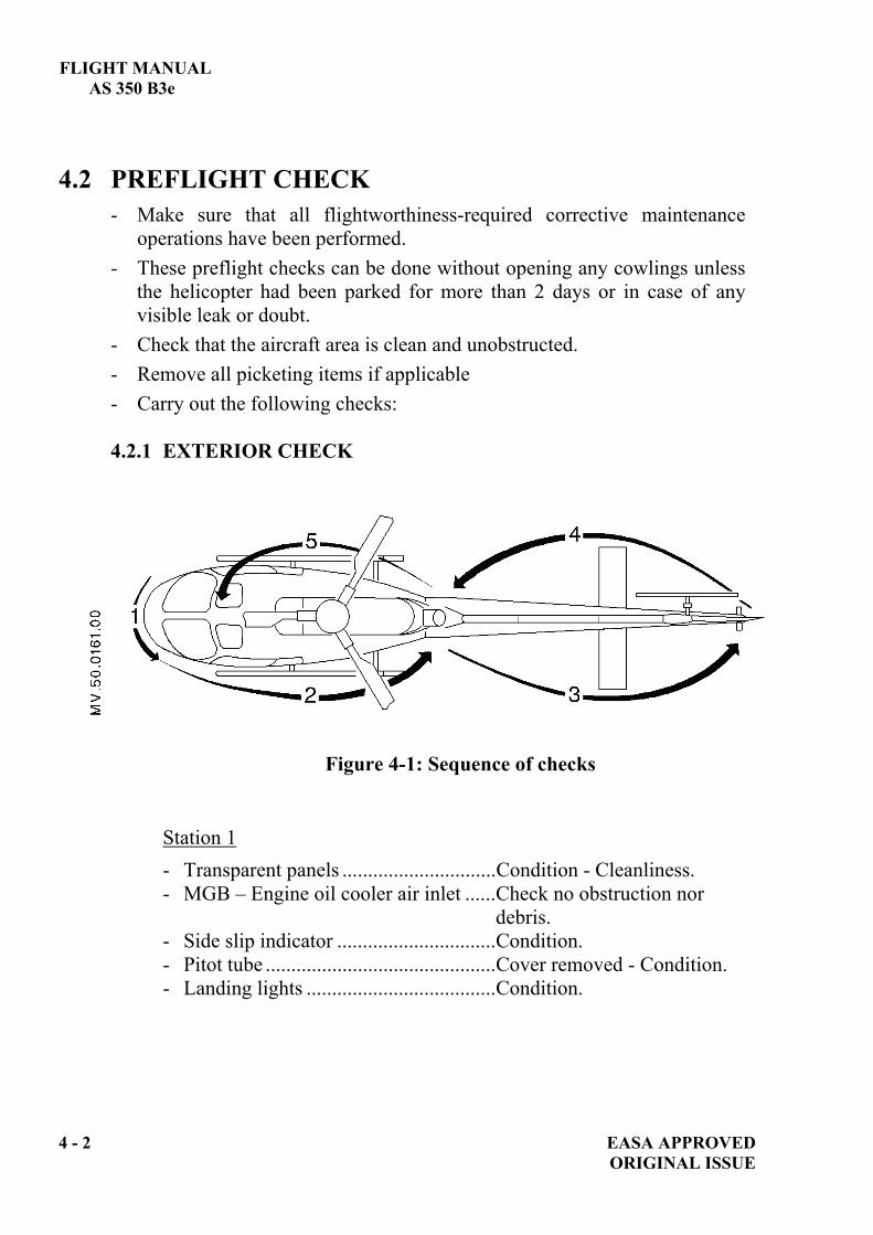
4.2.1 EXTERIOR CHECK
Figure 4-1: Sequence of checks
Station 1 - Transparent panels ..............................Condition - Cleanliness. - MGB – Engine oil cooler air inlet ......Check no obstruction nor
debris. - Side slip indicator ...............................Condition. - Pitot tube .............................................Cover removed - Condition. - Landing lights .....................................Condition.

FLIGHT MANUAL AS 350 B3e
EASA APPROVED 4 - 3 ORIGINAL ISSUE
Station 2 - Front door ........................................... Condition, jettison system
check. - Rear door ............................................ Condition, closed or open
locked (sliding door). - Left cargo door ................................... Open. - Loads and objects carried................... Secured. - Left cargo door ................................... Closed, locked. - Fuel tank and system .......................... Filler plug closed - Tank
sump drained. - MGB cowl .......................................... MGB oil level - Cowl locked. - All lower fairing panels...................... Locked. - Landing gear and foot step ................. Secure - Visual check. - Static ports.......................................... Clear, covers removed. - OAT sensors, antennas ....................... Condition. - Main rotor head and blades ................ Visual inspection , no impact. - Engine air intake................................. Clear (no water, snow, foreign
objects). - Engine cowl........................................ Locked. - Exhaust cover ..................................... Removed. - Rear cargo door .................................. Open. - Loads and objects carried................... Secured. - ELT..................................................... Check ARMED. - Rear cargo door .................................. Closed, locked. - Oil drain.............................................. No oil under scupper.

FLIGHT MANUAL AS 350 B3e
4 - 4 EASA APPROVED ORIGINAL ISSUE
Station 3 - Heat shield on tail rotor drive .............Condition, attachment. - Tail boom, antennas............................Condition - Fairing fasteners
locked. - Stabilizer, fin, external lights..............General condition. - Tail rotor guard (if fitted) ...................Condition, attachment. - TGB fairing.........................................Secured, fasteners locked. - TGB oil level ......................................Checked. - Tail skid ..............................................Condition, attachment.
Station 4 - Tail rotor head.....................................Condition, laminated bearing.
Checked for separation, cracks, etc. - Tail rotor blades ..................................Visual inspection , no impact. - Stabiliser, fin, external lights ..............General condition. - Tail boom, antennas............................Condition - Fairing fasteners
locked. - Heat shield on tail rotor drive .............Condition, attachment.
Station 5 - Oil drain ..............................................No oil under scupper. - EPU door.............................................Closed or EPU connected. - Engine cowl ........................................Locked. - Right cargo door .................................Open. - Loads and objects carried ...................Secured. - Right cargo door .................................Locked. - Main rotor head and blades.................Visual inspection, no impact. - MGB cowl...........................................No foreign objects on
transmission deck. Cowl locked.
- Hydraulic oil level ..............................Check reservoir level. - Engine oil level ...................................Check reservoir level. - Landing gear and foot step .................Secure – Visual check. - All lower fairing panels ......................Locked. - Door ....................................................Condition, jettison system
check. - External mirror (if fitted) ....................Set to avoid dazzling (night
flight).

FLIGHT MANUAL AS 350 B3e
EASA APPROVED 4 - 5 ORIGINAL ISSUE
4.2.2 INTERIOR CHECK - Cabin .................................................. Clean. - Fire extinguisher................................. Secured - Checked. - Fuses or breakers ................................ All set. - Loads and objects carried................... Stowed and secured. - Front door jettison systems ................ Check - Plastic guard
condition.
4.2.3 TURNAROUND CHECK - Overall aspect .................................... Condition, cleanliness. - Engine / MGB / TGB ......................... Oil level. - Main and tail rotor blades ..................Visual inspection, no impact. - Loads ................................................. Secured. - All cowlings ....................................... Locked. - Doors .................................................. Closed or sliding door open-
locked.
NOTE If the aircraft is to be parked for some time between flights, temporary picketing is recommended by fitting blanks, covers, and blade socks in winds above 40 kt (74 km/h). In this case, perform a complete pre-flight check.
FLIGHT MANUAL AS 350 B3e
4 - 6 EASA APPROVED ORIGINAL ISSUE
4.3 START UP 4.3.1 ENGINE PRESTART CHECK
- Seats and control pedals......................ADJUST and SECURE. - Seat belts .............................................FASTEN.
NOTE Copilot seat belts shall be fastened in all cases.
1. Rotor brake.......................................RELEASE, fully forward. 2. Fuel shut-off lever ............................FORWARD, plastic guard
condition. 3. Twist grip .........................................IDLE position. 4. Hydraulic pressure switch................ON. 5. [EMER SW].......................................CHECK ON position. 6. Starting selector................................OFF. 7. [BAT/EPU], [DCT/BAT] ....................ON. 8. Lighting circuits 1 and 2 test............PERFORM (if night flight
intended). 9. ICS and GPS nav. system ................ON. 10. Electric mirror (if installed) .............SET to avoid dazzling (night
flight). 11. [W/L TST] .........................................PERFORM.
Check TRQ indicates 100 % for 2 sec., then 0.
12. FIRE TST ........................................PERFORM. 13. [ACCU TST]......................................CHECK OFF position.

FLIGHT MANUAL AS 350 B3e
EASA APPROVED 4 - 7 ORIGINAL ISSUE
14. CWP lights ..................................CHECK: With battery power............. :
With EPU power ................ : Same lights as above +
15. VEMD ..........................................CHECK: . 3-data page: no message, . Vehicle page: no message, . Battery voltage > 22 V, . (Bleed valve open).
16. Control pedals ..............................Free travel, then left pedal 2 cm (0.8 in) forward.
17. Cyclic pitch...................................CENTER, friction adjusted. 18. Collective pitch ............................LOCK, friction adjusted. 19. Heating, demisting,
air conditioning (if installed)........OFF.
BATT
GENE ENG P PITOT HYDR
HORNFUEL P MGB P
TWT GRIP
FLIGHT MANUAL AS 350 B3e
4 - 8 EASA APPROVED ORIGINAL ISSUE
4.3.2 ENGINE STARTING 1. CWP..................................................CHECK GOV . 2. A/COL LT ........................................ON. 3. Starting selector ................................ON position. 4. Engine parameters.............................CHECK:
. N1 increases, . TOT remains below its limits, . Rotor is turning before N1 = 25%, . Engine oil pressure increases.
When N1 67 %
5. GENE ..............................................ON. 6. CWP..................................................CHECK: ENG P MGB P HYDR .
7. PITOT ..............................................ON, PITOT 8. Starting selector guard .....................SET. 9. All necessary systems ......................ON - TESTED.
(master avionics switch, lights..)
NOTE 1 In strong wind apply a little cyclic into wind.
NOTE 2 In case of failed engine start, return the starting selector to OFF, wait 30 sec., perform an engine crank (see paragraph 4.3.4). [FUEL P] set to ON during next engine start attempt.
NOTE 3 At N1 > 60 % the VEMD upper screen automatically switches to FLI display.
11. EPU (if installed) ........................... DISCONNECT, Make sure EPU door
is closed and locked. 12. CWP............................................... CHECK: GENE BATT .
FLIGHT MANUAL AS 350 B3e
EASA APPROVED 4 - 9 ORIGINAL ISSUE
4.3.3 RUN-UP CHECK
1. Hydraulic checks ................................. :
CAUTION If not locked, the collective pitch lever will move up when the accumulators are depleted or when the hydraulic cut-off switch on the collective is set to OFF.
Accumulator checks:
- Collective pitch ............................... CHECK correctly locked. - [ACCU TST] ...................................... PRESS. - CWP ................................................. CHECK HYDR flashes. - Collective / cyclic controls............... HANDS on. - Move the cyclic control 2 or 3 times on each axis
(+/- 10% of travel) and check for accumulator hydraulic assistance on pitch and roll (no control loads).
- [ACCU TST] ...................................... CHECK OFF position. - CWP ................................................. CHECK HYDR .

FLIGHT MANUAL AS 350 B3e
4 - 10 EASA APPROVED ORIGINAL ISSUE
Hydraulic pressure isolation check:
- Collective pitch.......................... CHECK correctly locked. - Hydraulic cutoff switch ............. SET to OFF. - CWP........................................... CHECK HYDR . - Check that loads are felt immediately and that cyclic can be
moved in pitch and roll with normal feedback loads. Yaw pedal loads increase.
- Hydraulic cutoff switch ............. SET to ON. - CWP........................................... CHECK HYDR after 3 to 4 sec.
Maintenance action must be performed prior to flight if this time is reduced to 1 sec. (at least one of the accumulators is faulty).
When minimum engine oil temperature is reached (Refer to
SECTION 2 §2.4.5): 2. Twist grip..........................................FLIGHT position.
When NR 340 rpm:
3. HORN ........................................... ON, HORN . CHECK audio warning:
. ON for NR 360 rpm.
. OFF for NR > 360 rpm. 4. NR indication ................................ CHECK in lower green range.
5. [FIRE TST]...................................... PERFORM, CHECK:
+ Gong sounds.
6. Parameter checks ........................... No warning light illuminated, Electrical system voltage and current, Engine oil pressure.
ENG FIRE

FLIGHT MANUAL AS 350 B3e
EASA APPROVED 4 - 11 ORIGINAL ISSUE
4.3.4 CRANKING The cranking procedure shall be performed after a failed or aborted start and can be used for check or maintenance purposes. Proceed as follows:
1. Start selector .................................. OFF. 2. Emergency fuel
shut-off lever .................................. FORWARD. 3. N1 ................................................... CHECK 10 %. 4. [CRANK] ......................................... PRESS for 20 sec. max.
CAUTION
Do not crank the engine with the emergency fuel shutoff valve closed as this could damage the engine high pressure fuel pump.
4.4 TAKEOFF 4.4.1 BEFORE TAKEOFF CHECK
1. Doors .................................................. CLOSED or sliding doors OPEN LOCKED.
2. Cyclic and collective frictions............ AS REQUIRED. 3. Landing light ...................................... AS REQUIRED. 4. Temperatures and pressures ............... NORMAL RANGE. 5. CWP ................................................... All lights OFF. 6. Collective pitch................................... UNLOCK.
NOTE Adjust collective and cyclic frictions so that friction loads are felt by the pilot when moving the flight controls.
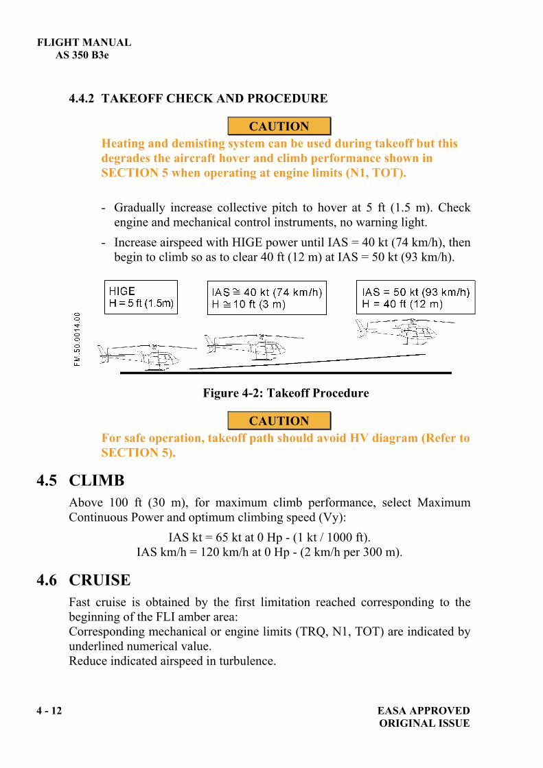
FLIGHT MANUAL AS 350 B3e
4 - 12 EASA APPROVED ORIGINAL ISSUE
4.4.2 TAKEOFF CHECK AND PROCEDURE
CAUTION Heating and demisting system can be used during takeoff but this degrades the aircraft hover and climb performance shown in SECTION 5 when operating at engine limits (N1, TOT). - Gradually increase collective pitch to hover at 5 ft (1.5 m). Check
engine and mechanical control instruments, no warning light. - Increase airspeed with HIGE power until IAS = 40 kt (74 km/h), then
begin to climb so as to clear 40 ft (12 m) at IAS = 50 kt (93 km/h).
Figure 4-2: Takeoff Procedure
CAUTION For safe operation, takeoff path should avoid HV diagram (Refer to SECTION 5).
4.5 CLIMB Above 100 ft (30 m), for maximum climb performance, select Maximum Continuous Power and optimum climbing speed (Vy):
IAS kt = 65 kt at 0 Hp - (1 kt / 1000 ft). IAS km/h = 120 km/h at 0 Hp - (2 km/h per 300 m).
4.6 CRUISE Fast cruise is obtained by the first limitation reached corresponding to the beginning of the FLI amber area: Corresponding mechanical or engine limits (TRQ, N1, TOT) are indicated by underlined numerical value. Reduce indicated airspeed in turbulence.
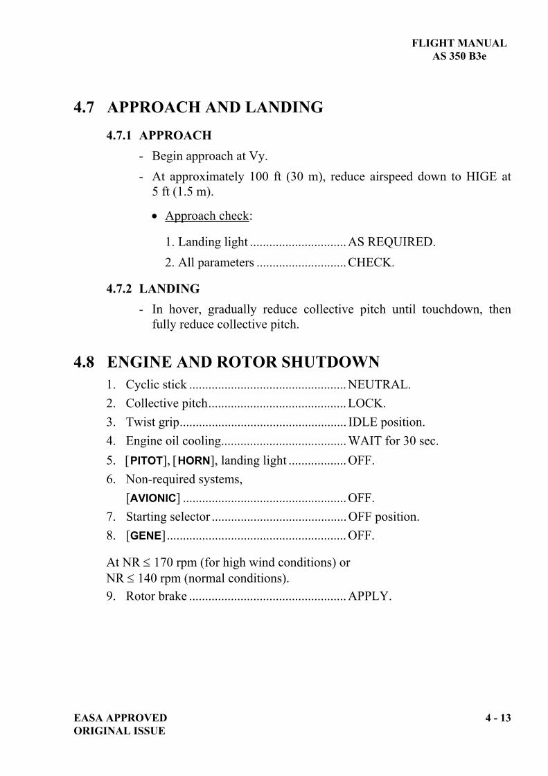
FLIGHT MANUAL AS 350 B3e
EASA APPROVED 4 - 13 ORIGINAL ISSUE
4.7 APPROACH AND LANDING 4.7.1 APPROACH
- Begin approach at Vy. - At approximately 100 ft (30 m), reduce airspeed down to HIGE at
5 ft (1.5 m).
Approach check:
1. Landing light .............................. AS REQUIRED. 2. All parameters ............................ CHECK.
4.7.2 LANDING - In hover, gradually reduce collective pitch until touchdown, then
fully reduce collective pitch. 4.8 ENGINE AND ROTOR SHUTDOWN
1. Cyclic stick ................................................. NEUTRAL. 2. Collective pitch........................................... LOCK. 3. Twist grip.................................................... IDLE position. 4. Engine oil cooling....................................... WAIT for 30 sec. 5. PITOT , HORN , landing light .................. OFF. 6. Non-required systems, [AVIONIC] ................................................... OFF. 7. Starting selector .......................................... OFF position. 8. [GENE]........................................................ OFF.
At NR 170 rpm (for high wind conditions) or NR 140 rpm (normal conditions). 9. Rotor brake ................................................. APPLY.

FLIGHT MANUAL AS 350 B3e
4 - 14 EASA APPROVED ORIGINAL ISSUE
When rotor is stopped:
10. GPS navigation system ........................ OFF.
11. A/COL LT ........................................... OFF.
BEFORE LEAVING HELICOPTER
12. VEMD.................................................. CHECK of Flight Report page data: Operating time (counted from N1 > 60 % until N1 < 50 %). N1 and N2 cycles ..................... CHECK (Indicated in white characters
and above 0). Usage Advisory messages: FAILURE or OVERLIMIT DETECTED .
13. [DCT/BAT], [BAT/EPU] ........................ OFF. 14. Pitot, air intake and exhaust covers, blade socks as required.
4.9 MISCELLANEOUS PROCEDURES AND DATA
4.9.1. TANK CAPACITIES
Maximum capacity 540 liters (142.7 US gal) (427 kg) (941 lb).

FLIGHT MANUAL
AS 350 B3e
Fuel gauge
10 = 538.7 liters (425.6 kg) (142.3 US gal)(938 lb) usable fuel quantity.
: 15 min. of flight time remains at MCP.
NOTE 1 The unusable fuel quantity is reached when zero is indicated on the fuel gauge.
NOTE 2 Fuel quantity indication in kg and fuel flow indication in kg/h is based on a fuel density of 0.79 kg/l.
4.10 EXTREME WEATHER OPERATIONS 4.10.1 HIGH WIND OPERATION (WIND ABOVE 30 KT- 56 KM/H)
Parking - Park the helicopter head into the wind. Maintain rotor brake
applied with one blade at 12 o’clock. Keep blade socks until start up.
- For wind above 40 kt (74 km/h) the helicopter must be tied down.
EASA APPROVED 4 - 15 ORIGINAL ISSUE

FLIGHT MANUAL AS 350 B3e
4 - 16 EASA APPROVED ORIGINAL ISSUE
Start up - When the rotor begins to turn, apply a small cyclic stick input
into the wind. - As soon as N1 > 67 %:
Twist grip..................................FLIGHT position.
Run up check - Perform the hydraulic checks with the twist grip in FLIGHT
position and NR at nominal speed.
Engine and rotor shutdown - Allow engine oil to cool with twist grip in FLIGHT position.
NOTE
Start up and shutdown have been demonstrated up to 40 kt (74 km/h) of wind from any direction and for 50 kt (93 km/h) headwind.
4.10.2 COLD WEATHER OPERATION
Refer to SUP.4 "Instructions for use in cold weather".
FLIGHT MANUAL
AS 350 B3e
SECTION 5.1 REGULATORY PERFORMANCE
Page5.1 INTRODUCTION ........................................................................................5-1 5.2 DEMONSTRATED WIND ENVELOPES ................................................5-1 5.3 ENGINE HEALTH CHECK.......................................................................5-1
5.3.1 BEFORE TAKEOFF .........................................................................5-1 5.3.2 ENGINE HEALTH CHECK PROCEDURE ..................................5-1
5.4 AIR DATA SYSTEM CALIBRATION .....................................................5-7 5.5 HEIGHT - VELOCITY DIAGRAM ..........................................................5-8 5.6 HOVER IN GROUND EFFECT...............................................................5-10 5.7 HOVER OUT OF GROUND EFFECT....................................................5-11 5.8 CORRECTED WEIGHT...........................................................................5-12 5.9 RATE OF CLIMB ......................................................................................5-13 5.10 GLIDE DISTANCE IN AUTOROTATION............................................5-14 5.11 NOISE LEVEL ...........................................................................................5-14
EASA APPROVED 5 - i ORIGINAL ISSUE

FLIGHT MANUAL AS 350 B3e
LIST OF FIGURES
Page
FIGURE 5 - 1 : ENGINE HEALTH CHECK (TRQ MARGIN ISO N1) ........ 5-5 FIGURE 5 - 2 : ENGINE HEALTH CHECK (TRQ MARGIN ISO TOT)..... 5-6 FIGURE 5 - 3 : AIR DATA SYSTEM CALIBRATION ................................... 5-7 FIGURE 5 - 4 : HEIGHT / VELOCITY ENVELOPE....................................... 5-9 FIGURE 5 - 5 : IGE HOVERING FLIGHT PERFORMANCE..................... 5-10 FIGURE 5 - 6 : OGE HOVERING FLIGHT PERFORMANCE................... 5-11 FIGURE 5 - 7 : DETERMINATION OF CORRECTED WEIGHT.............. 5-12 FIGURE 5 - 8 : RATE OF CLIMB .................................................................... 5-13
5 - ii EASA APPROVED ORIGINAL ISSUE

FLIGHT MANUAL AS 350 B3e
EASA APPROVED 5 - 1 ORIGINAL ISSUE
5.1 INTRODUCTION The following performance curves apply to the basic version of the aircraft. Refer to supplement when optional equipment is fitted.
5.2 DEMONSTRATED WIND ENVELOPES 5.2.1 STARTING AND STOPPING ROTOR WIND ENVELOPE
Starting and stopping the rotor has been demonstrated for winds of 40 kt (74 km/h) from any direction and 50 kt (93 km/h) with a headwind (forward center axis +/- 30°).
5.2.2 WIND ENVELOPE IN HOVER Hovering with winds from any direction up to 17 kt (31 km/h) has been demonstrated over the entire flight envelope although it is not to be taken as a limit. For example hover at sea level at maximum gross weight and for all c.g. locations has been substantiated at 30 kt (55 km/h).
5.3 ENGINE HEALTH CHECK 5.3.1 BEFORE TAKEOFF
In HIGE at 5ft (1.5 m) and before initiating forward flight, pull the collective pitch lever slightly to ensure that the N1 can increase by at least 1%, without exceeding the max. transient rating.
5.3.2 ENGINE HEALTH CHECK PROCEDURE The engine health check consists in checking the power margin (TRQ MARGIN ISO N1) and (TRQ MARGIN ISO TOT). Checking can be performed using the VEMD data (Refer to paragraph 5.3.2.1) or manually recorded parameters (Refer to paragraph 5.3.2.2).

FLIGHT MANUAL AS 350 B3e
5 - 2 EASA APPROVED ORIGINAL ISSUE
5.3.2.1 FADEC engine health check The engine health check is performed in level flight MCP,
heating and demisting system OFF. Prefer an altitude where the engine is operating close to the
N1 MCP limit. Stabilize level flight MCP for at least 2 min. before
initiating the engine health check. Read the results displayed on VEMD after the end of the
procedure. The engine health check is satisfactory if:
- TRQ MARGIN / TOT is 0%, “GOOD” displayed, and - TRQ MARGIN / N1 is 0%,“GOOD” displayed.
5.3.2.2 Manual procedure The engine health check is performed in level flight MCP,
heating and demisting system OFF. Prefer an altitude where the engine is operating close to the
N1 MCP limit. Stabilize level flight MCP for at least 2 min. before
recording the following parameters: TRQ, N1, NR, Hp, OAT and TOT.
NOTE The altimeter must be set to 1013.2 hPa to display Hp.
Refer to the ENGINE HEALTH CHECK charts (Fig. 5-1 and Fig. 5-2). Use the charts in the direction shown by the arrows in examples.
Torque Margin ISO N1 Calculation (Fig 5-1) - Plot point P on the chart according to the recorded N1 and
OAT parameters. - Plot point P’ according to Hp, then note the normalized
TRQ value. - Plot point P’' according to the recorded NR parameter then
note the TRQ correction value. The result is calculated as follows: - TRQ min = normalized TRQ + TRQ correction. - TRQ MARGIN ISO N1 = TRQ flight – TRQ min.

FLIGHT MANUAL AS 350 B3e
EASA APPROVED (5 - 4 blank) 5 - 3 ORIGINAL ISSUE
Torque Margin ISO TOT Calculation (Fig. 5-2) - Plot point T on the chart according to the recorded TOT
and Hp. - Plot point T’ according to OAT parameters. - Plot point T'' according to Hp, then note the
NORMALIZED TRQ value. - Plot point T''' according to the recorded NR parameter,
then note the TRQ CORRECTION value. The result is calculated as follows: - TRQ min = normalized TRQ + TRQ correction. - TRQ MARGIN ISO TOT = TRQ flight – TRQ min. The engine health check is satisfactory if:
- “TRQ MARGIN ISO N1” value is positive. and - “TRQ MARGIN ISO TOT” value is positive.
NOTE
The manual procedure may lead to different results compared to the FADEC procedure because it is less sophisticated. Preference shall be given to the use of FADEC procedure and the manual one should only be used if the FADEC procedure gives obviously doubtful or incorrect results.

FLIGHT MANUAL AS 350 B3e
PAGE INTENTIONALLY LEFT BLANK
5 - 4 EASA APPROVED ORIGINAL ISSUE
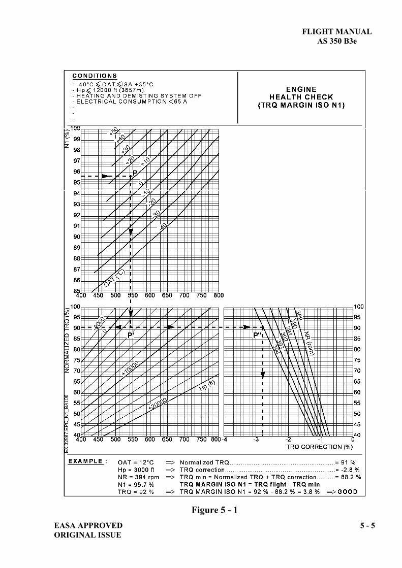
FLIGHT MANUAL AS 350 B3e
EASA APPROVED 5 - 5 ORIGINAL ISSUE
Figure 5 - 1

FLIGHT MANUAL AS 350 B3e
Figure 5 - 2
5 - 6 EASA APPROVED ORIGINAL ISSUE

FLIGHT MANUAL
AS 350 B3e
5.4 AIR DATA SYSTEM CALIBRATION No condition AIR DATA SYSTEM CALIBRATION
Figure 5 - 3
EASA APPROVED 5 - 7 ORIGINAL ISSUE

FLIGHT MANUAL AS 350 B3e
5 - 8 EASA APPROVED ORIGINAL ISSUE
5.5 HEIGHT - VELOCITY DIAGRAM The avoidance zone is defined by four points: A, B, C, D (refer to figure 5-4).
- Point A : low hover point
Point A is at 8 ft (2.5 m) skid height at zero airspeed.
- Point B :
Point B is defined by: a constant height of 25 ft (8 m), a constant airspeed of 40 kt (74 km/h).
- Point C :
Point C is defined by: a constant height of 100 ft (30 m), a variable airspeed depending on the density altitude and on the
aircraft weight as determined by line (C).
- Point D :
Point D is defined by: a variable height depending on the density altitude and on the
aircraft weight as determined by line (D), a constant zero airspeed.

FLIGHT MANUAL
AS 350 B3e
Figure 5 - 4
EASA APPROVED 5 - 9 ORIGINAL ISSUE

FLIGHT MANUAL AS 350 B3e
5 - 10 EASA APPROVED ORIGINAL ISSUE
5.6 HOVER IN GROUND EFFECT
Figure 5 - 5
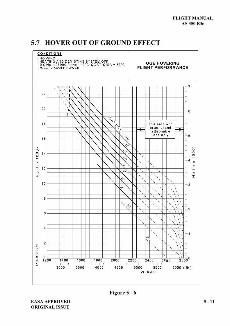
FLIGHT MANUAL AS 350 B3e
EASA APPROVED 5 - 11 ORIGINAL ISSUE
5.7 HOVER OUT OF GROUND EFFECT
Figure 5 - 6

FLIGHT MANUAL AS 350 B3e
5 - 12 EASA APPROVED ORIGINAL ISSUE
5.8 CORRECTED WEIGHT
Figure 5 - 7
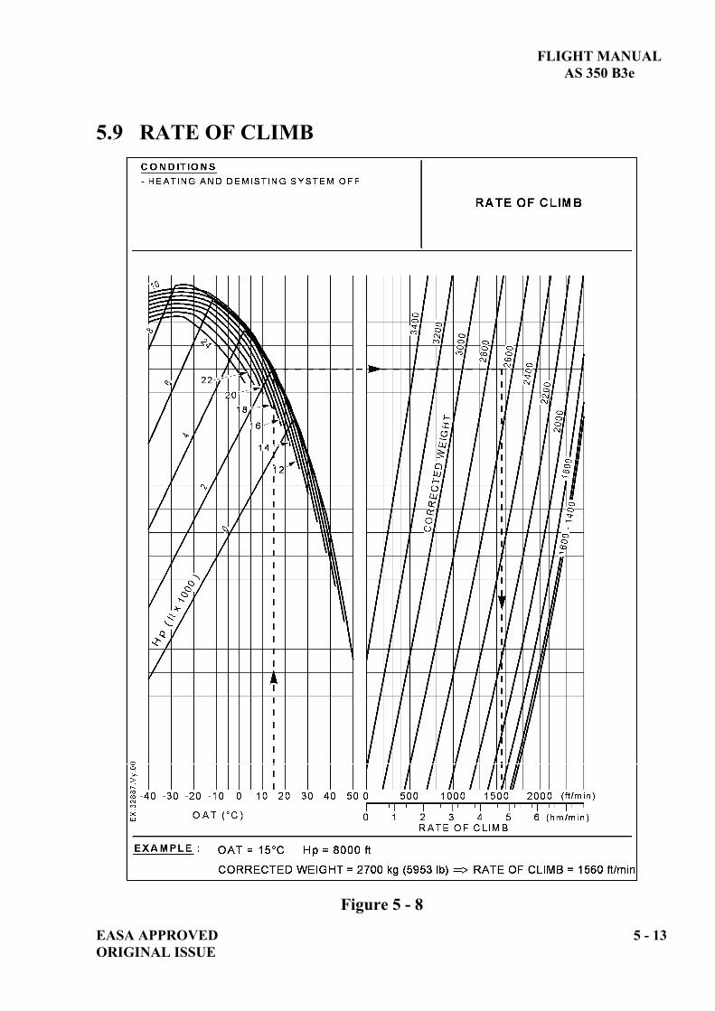
FLIGHT MANUAL AS 350 B3e
EASA APPROVED 5 - 13 ORIGINAL ISSUE
5.9 RATE OF CLIMB
Figure 5 - 8

FLIGHT MANUAL AS 350 B3e
5.10 GLIDE DISTANCE IN AUTOROTATION The distance flown in autorotation is:
0.54 NM per 1000 ft at IAS kt = 65 kt and NR 410 rpm
1000 m (distance) per 300 m (height) at IAS km/h = 120 km/h and NR 410 rpm
5.11 NOISE LEVEL Noise characteristics as defined by the conditions of Chapter 11 of ICAO Annex 16 and Appendix J of FAR Part 36 are as follows:
Flight Phase
Noise Level as per ICAO Annex 16 and
FAR Part 36 (dB SEL)
ICAO / FAR limits
(dB SEL)
Flyover at 0.9VH *With VH =135 kt (250 km/h) TAS
84.4 86.5
(*) VH = Maximum speed in level flight at power not exceeding maximum continuous power, for sea level pressure and 25°C ambient conditions at MTOW.
5 - 14 EASA APPROVED ORIGINAL ISSUE

FLIGHT MANUAL
AS 350 B3e
SUPPLEMENT
LIST OF SUPPLEMENTS, INCOMPATIBILITY OF USE,
EFFECT ON PERFORMANCE DATA.
IMPORTANT NOTE
THE INFORMATION CONTAINED HEREIN SUPPLEMENTS OR SUPERSEDES THE INFORMATION GIVEN IN THE BASIC FLIGHT MANUAL AND/OR THE SUPPLEMENTS LISTED IN SECTION SUP.0.
THE EFFECTIVITY OF THE SUPPLEMENT AT THE LATEST REVISION IS SPECIFIED ON THE LIST OF EFFECTIVE PAGES.
E U R O C O P T E R D i r e c t i o n T e c h n i q u e S u p p o r t Aéroport international Marseille-Provence 13725 Marignane Cedex – France
EASA APPROVED SUP.0-TITLEORIGINAL ISSUE


FLIGHT MANUAL
AS 350 B3e
LIST OF TEMPORARY REVISION EFFECTIVE PAGES The manual contains the following additional yellow pages.
No. PAGE DATE No. PAGE DATE
EASA APPROVED SUP.0-CORIGINAL ISSUE
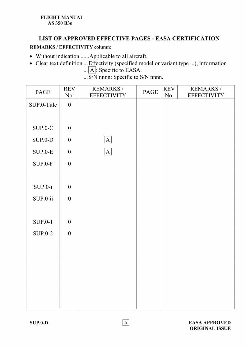
FLIGHT MANUAL AS 350 B3e
SUP.0-D A
EASA APPROVED ORIGINAL ISSUE
LIST OF APPROVED EFFECTIVE PAGES - EASA CERTIFICATION REMARKS / EFFECTIVITY column:
Without indication ......Applicable to all aircraft. Clear text definition ...Effectivity (specified model or variant type ...), information
... A : Specific to EASA.
...S/N nnnn: Specific to S/N nnnn.
PAGE REV No.
REMARKS / EFFECTIVITY PAGE REV
No. REMARKS /
EFFECTIVITY SUP.0-Title 0
SUP.0-C 0
SUP.0-D 0 A
SUP.0-E 0 A
SUP.0-F 0
SUP.0-i 0
SUP.0-ii 0
SUP.0-1 0
SUP.0-2 0

FLIGHT MANUAL
AS 350 B3e
EASA APPROVED A ORIGINAL ISSUE
SUP.0-E
LOG OF APPROVED NORMAL REVISIONS BASIC RFM REVISIONS - EFFECTIVITY EASA
NORMAL REVISION 0 - DECEMBER 2010 EASA approval No. 10035374 on June 17, 2011
Title New flight manual. Revised
information All pages.
Deleted information None

FLIGHT MANUAL AS 350 B3e
CUSTOMIZATIONA/C: AS 350 B3e – S/N:
SECTION PAGE ISSUE SECTION PAGE ISSUE
THIS AIRCRAFT DOES NOT OFFER ANY PARTICULAR FEATURES REQUIRING THE CUSTOMIZATION ON THE FLIGHT MANUAL ON
GREEN PAGES
SUP.0-F EASA APPROVED ORIGINAL ISSUE

FLIGHT MANUAL AS 350 B3e
EASA APPROVED SUP.0- i ORIGINAL ISSUE
LIST OF SUPPLEMENTS Some supplements covering installations or procedures not used on this helicopter may be withdrawn from this manual. The complete list of supplements appears on this page.
No. DESCRIPTION 0 List of supplements, incompatibility of use, effect on performance data 1 Reserved 2 Reserved 3 Reserved 4 Instructions for operations in cold weather 5 Reserved 6 Autorotation landing training procedure 7 Hydraulic failure training procedure 8 Reserved 9 Reserved 10 Reserved 11 Reserved 12 External Load Transport : Cargo Sling 750 kg (1660 lb) 13 External Load Transport : Cargo Swing 1400 kg (3086 lb) with
“SIREN” release unit 13.1 External Load Transport : Cargo Swing 1400 kg (3086 lb) with
“SIREN” fixed release unit. 13.2 External Load Transport : Cargo Swing 1400 kg (3086 lb) with
“ON-BOARD” release unit. 14 Sand Filter 15 Reserved 16 SFIM 85 T 31 (3-axis) Automatic Flight Control System 17 Emergency Floatation Gear AERAZUR 18 "Breeze" or "Air Equipment" Electric Hoist 136 kg (300 lb) 19 "Breeze" Electric Hoist 204 kg (450 lb)
19.1 "Breeze" Electric Hoist 204 kg (450 lb), grip with support bracket

FLIGHT MANUAL AS 350 B3e
SUP.0-ii EASA APPROVED ORIGINAL ISSUE
LIST OF SUPPLEMENTS (cont'd)
No DESCRIPTION 20 Hydraulic Pump Drive on MGB 21 Two-passenger Front Seat 22 Long and Short Footsteps 23 Dual Hydraulic System 24 Reserved 25 Reserved 26 Reserved 27 Reserved 28 Maximum internal gross weight increased to 2370 kg (5225 lb) 29 200 A Starter generator 30 to 49
Reserved
50 Ferry Flight Fuel Tank 51 Reserved 52 "BAMBI BUCKET" model 2732S 53 Reserved 54 Reserved 55 “GARMIN GNS 430/430W” GPS 56 Abseiling installation

FLIGHT MANUAL
AS 350 B3e
1 INCOMPATIBILITY OF USE BETWEEN OPTIONAL EQUIPMENT ITEMS
The following list is non-exhaustive and covers only those EASA-approved equipment items which are incompatible with one or several other items.
NOTE Incompatibility of installation between equipments is stated in the Master Servicing Recommendations (P.R.E.).
Operation of the following Makes operation with theinstallations: following equipment items
impossible:
Items Flight Manual supplement Items 15 Emergency floatation gear (SUP.17) 32* - 66 21 Ferry flight fuel tank (SUP.50) 22 - 23 - 3222 External load carrying installation "Cargo
sling" (SUP.12) 21 - 25 - 32 - 44 - 66
23 External load carrying installation "Cargo swing" (SUP.13 / SUP.13.1 / SUP.13.2)
21 - 25 - 32 - 44 - 66
25 Air ambulance installation 22 - 23 - 32
32 Electric hoist (SUP.18 / SUP.19 / SUP.19.1) 15* - 21 - 22 - 23 - 2544 - 66
44 Two-passenger front seat (SUP.21) 22 - 23 - 3266 Abseiling installation (SUP.56) 15 - 22 - 23 - 32 AA Maximum internal gross weight increased to
2370 kg (SUP.28) AB
AB Low landing gear installation AA(*) Hoisting remains possible when the floats are folded.
EASA APPROVED SUP.0-1ORIGINAL ISSUE
FLIGHT MANUAL AS 350 B3e
2 INFLUENCE OF OPTIONAL EQUIPMENT ITEMS ON PERFORMANCE DATA
When several optional equipment items are used simultaneously, the basic performance data must be reduced by the value corresponding to the influence of each optional item.
2.1 Approved performance data
- Takeoff weights: When the installation of an optional equipment item modifies the takeoff weights specified in the basic Flight Manual SECTION 5.1, the relevant Supplement either provides the new takeoff weights by new charts or by a penalty relative to the basic flight performance.
- Rates of climb: When the rates of climb in the basic Flight Manual SECTION 5.1 are modified, the relevant Supplement either provides a new chart or specifies a reduction with respect to the basic flight performance.
2.2 Complementary performance data The influences of the optional equipment items are specified in SECTION 5.2 "Complementary performance data".
SUP.0-2 EASA APPROVEDORIGINAL ISSUE

EASA APPROVED SUP.4-TITLE ORIGINAL ISSUE
FLIGHT MANUAL
AS 350 B3e
SUPPLEMENT
INSTRUCTIONS FOR OPERATIONS IN COLD WEATHER
IMPORTANT NOTE THE INFORMATION CONTAINED HEREIN SUPPLEMENTS OR SUPERSEDES THE INFORMATION GIVEN IN THE BASIC FLIGHT MANUAL AND/OR THE SUPPLEMENTS LISTED IN SECTION SUP.0. THE EFFECTIVITY OF THE SUPPLEMENT AT THE LATEST REVISION IS SPECIFIED ON THE LIST OF EFFECTIVE PAGES.
E U R O C O P T E R D i r e c t i o n T e c h n i q u e S u p p o r t Aéroport international Marseille-Provence 13725 Marignane Cedex – France


FLIGHT MANUAL
AS 350 B3e
EASA APPROVED A ORIGINAL ISSUE
SUP.4-A
LIST OF APPROVED EFFECTIVE PAGES - EASA CERTIFICATION REMARKS / EFFECTIVITY column:
Without indication ......Applicable to all aircraft. Clear text definition ...Effectivity (specified model or variant type ...), information
... A : Specific to EASA.
...S/N nnnn: Specific to S/N nnnn.
PAGE REV No.
REMARKS / EFFECTIVITY PAGE REV
No. REMARKS /
EFFECTIVITY SUP.4-Title 0
SUP.4-A 0 A
SUP.4-B 0 A
SUP.4-1 0
SUP.4-2 0
SUP.4-3 0
SUP.4-4 0
SUP.4-5 0

FLIGHT MANUAL
AS 350 B3e
SUP.4-B A
EASA APPROVEDORIGINAL ISSUE
LOG OF APPROVED NORMAL REVISIONS BASIC RFM REVISIONS - EFFECTIVITY EASA
NORMAL REVISION 0 - DECEMBER 2010 EASA approval No. 10035374 on June 17, 2011
Title New flight manual. Revised
information All pages.
Deleted information None
FLIGHT MANUAL AS 350 B3e
EASA APPROVED SUP.4-1 ORIGINAL ISSUE
1 GENERAL This supplement details the procedures to be followed when the aircraft is operated in cold weather or snowy climatic conditions. Aircraft servicing does not require any special tools or routine replacement.
NOTE Use of 3 to 3.9 cSt synthetic oil is recommended for low temperature operation.
2 LIMITATIONS
The limitations specified in the basic flight manual and in the flight manual supplements remain applicable.
3 EMERGENCY PROCEDURES
The emergency procedures specified in the basic flight manual and in the flight manual supplements remain applicable.
NOTE Following an engine failure at light weight, the stabilized NR speed may be below the audio warning threshold, the pilot can switch off the horn using the [HORN] pushbutton.
4 NORMAL PROCEDURES
The normal procedures specified in the basic flight manual and in the flight manual supplements remain applicable and are completed or modified by the following: 4.1 GENERAL RECOMMENDATIONS
For rational operation of the aircraft in cold weather and snow, it is recommended to carry out the following basic operations. - Remove ice or snow deposits from the whole of the aircraft,
particularly at hinges and dynamic and control components (main rotor, rotor mast, tail rotor drive and tail rotor, flight controls, engine controls).
- When the aircraft has been subject to very low temperatures, it is recommended: either to perform regular ground runs every two hours for
temperatures of around - 20C or every hour for lower temperatures.
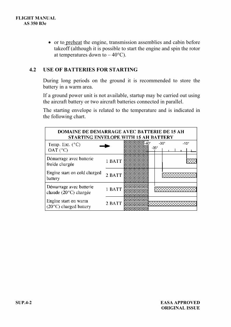
FLIGHT MANUAL AS 350 B3e
SUP.4-2 EASA APPROVED ORIGINAL ISSUE
or to preheat the engine, transmission assemblies and cabin before takeoff (although it is possible to start the engine and spin the rotor at temperatures down to – 40°C).
4.2 USE OF BATTERIES FOR STARTING
During long periods on the ground it is recommended to store the battery in a warm area. If a ground power unit is not available, startup may be carried out using the aircraft battery or two aircraft batteries connected in parallel. The starting envelope is related to the temperature and is indicated in the following chart.

FLIGHT MANUAL AS 350 B3e
EASA APPROVED SUP.4-3 ORIGINAL ISSUE
4.3 PREFLIGHT CHECK
In addition to the inspections specified in the basic flight Manual, perform the following operations and inspections: - Main rotor blades................: Remove snow and ice. If necessary,
remove ice from rotor blades using a hot air flow at a temperature not exceeding 80°C.
- Main rotor hub and mast ....: Absence of ice on the swashplates, the scissors, the servo controls and the rotor head spring antivibrator.
- Power plant.........................: • Remove the air intake cover and the
exhaust nozzle blank after removing snow from the aircraft surface.
• Remove snow and ice accretion in the vicinity of the air intake and on either side of the screen.
• Visually check for snow and ice inside the air intake duct.
• Inspect drains, un-blanked scuppers; check for snow and ice on vents and static ports.
- Tail rotor.............................: • No ice on the TRH assembly
(blades, pitch change rods, ...). • Manually rotate the tail rotor so
that the main rotor performs one turn at least then check: - swashplate rotation (rotor brake
not stuck), - TRH rotation, - freewheel operation.
NOTE It is mandatory to clear the air intake.
FLIGHT MANUAL AS 350 B3e
SUP.4- 4 EASA APPROVED ORIGINAL ISSUE
- Structure............................. : • Remove the cabin cover once the
inspection is over, to prevent icing. • Make sure that the windshield
wiper is not stuck on the canopy. - Flight and Engine controls. :
• Before operating the controls, it is recommended to heat-up the inside of the cabin.
• Operate the cyclic and tail rotor controls progressively, then operate the rotor brake control, twist grip and collective pitch control over their complete travel.
4.4 RUN-UP CHECK
When the outside air temperature is below –20°C, the run-up check is modified as follows: - Hydraulic checks................ :
• Proceed as for normal procedure and evaluate the loads when hydraulic switch is set to off. Complete the checks.
• If operating loads were evaluated higher than at normal temperatures, move the cyclic stick 3-4 cm forward (nose-down) for 2 minutes to warm up the spherical thrust bearings.
NOTE It is not recommended tooperate the cyclic and tail rotor controls over their completetravel range.
FLIGHT MANUAL AS 350 B3e
EASA APPROVED SUP.4-5 ORIGINAL ISSUE
- Yaw pedals ........................: Move the pedals over approximately 50% of their travel range on either side of the mid-position.
4.5 AFTER LAST FLIGHT OF THE DAY
The normal procedures described in the basic flight manual are to be completed by the following: - When the rotor stops turning, position the cyclic pitch stick close to
the neutral position and the collective pitch lever locked at full low pitch, with tail rotor blades in the horizontal position.
- Care must be taken not to leave doors open. - Install the air intake cover and exhaust nozzle blank. - When the aircraft is parked in an unsheltered area, it is recommended
to apply anti-icing products and to carry out aircraft blanking and mooring.
5 PERFORMANCE
The performance data specified in the basic flight manual and in the flight manual supplements remain applicable.


EASA APPROVED SUP.6-TITLEORIGINAL ISSUE
FLIGHT MANUAL
AS 350 B3e
SUPPLEMENT
AUTOROTATION LANDING TRAINING PROCEDURE
IMPORTANT NOTE
THE INFORMATION CONTAINED HEREIN SUPPLEMENTS OR SUPERSEDES THE INFORMATION GIVEN IN THE BASIC FLIGHT MANUAL AND/OR THE SUPPLEMENTS LISTED IN SECTION SUP.0.
THE EFFECTIVITY OF THE SUPPLEMENT AT THE LATEST REVISION IS SPECIFIED ON THE LIST OF EFFECTIVE PAGES.
E U R O C O P T E R D i r e c t i o n T e c h n i q u e S u p p o r t Aéroport international Marseille-Provence 13725 Marignane Cedex – France


FLIGHT MANUAL AS 350 B3e
EASA APPROVED AORIGINAL ISSUE
SUP.6-A
LIST OF APPROVED EFFECTIVE PAGES - EASA CERTIFICATION REMARKS / EFFECTIVITY column:
Without indication ......Applicable to all aircraft. Clear text definition ...Effectivity (specified model or variant type ...), information
... A : Specific to EASA.
...S/N nnnn: Specific to S/N nnnn.
PAGE REVNo.
REMARKS / EFFECTIVITY PAGE REV
No.REMARKS /
EFFECTIVITYSUP.6-Title 0
SUP.6-A 0 A
SUP.6-B 0 A
SUP.6-1 0
SUP.6-2 0
SUP.6-3 0

FLIGHT MANUAL
AS 350 B3e
SUP.6-B A
EASA APPROVEDORIGINAL ISSUE
LOG OF APPROVED NORMAL REVISIONS BASIC RFM REVISIONS - EFFECTIVITY EASA
NORMAL REVISION 0 - DECEMBER 2010 EASA approval No. 10035374 on June 17, 2011
Title New flight manual. Revised
information All pages.
Deleted information None
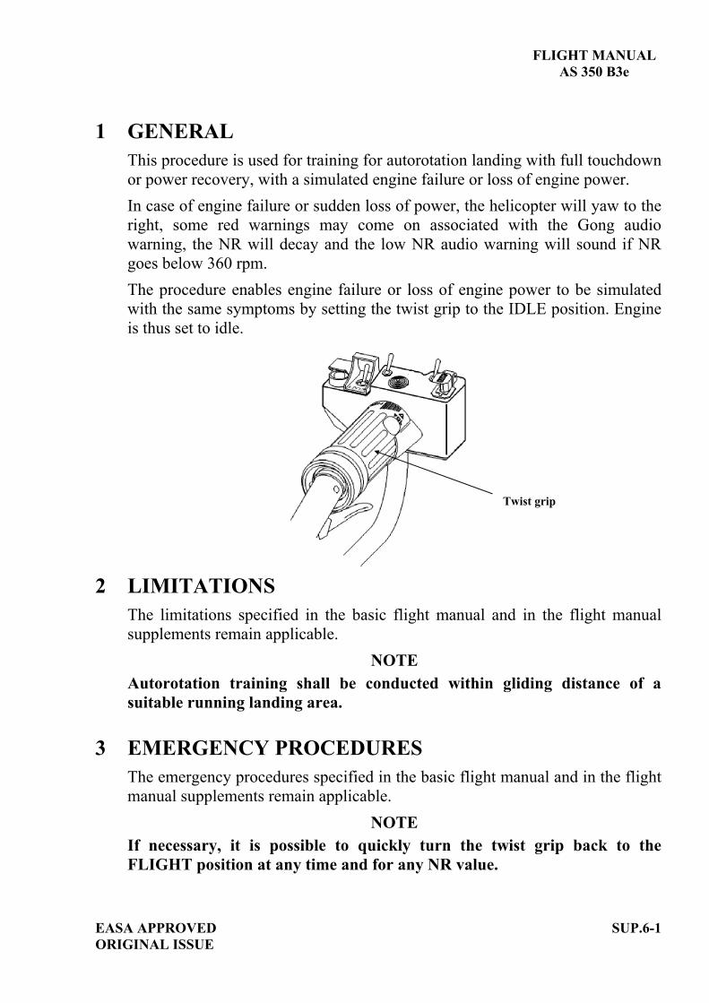
FLIGHT MANUAL AS 350 B3e
EASA APPROVED SUP.6-1 ORIGINAL ISSUE
1 GENERAL This procedure is used for training for autorotation landing with full touchdown or power recovery, with a simulated engine failure or loss of engine power. In case of engine failure or sudden loss of power, the helicopter will yaw to the right, some red warnings may come on associated with the Gong audio warning, the NR will decay and the low NR audio warning will sound if NR goes below 360 rpm. The procedure enables engine failure or loss of engine power to be simulated with the same symptoms by setting the twist grip to the IDLE position. Engine is thus set to idle.
2 LIMITATIONS
The limitations specified in the basic flight manual and in the flight manual supplements remain applicable.
NOTE Autorotation training shall be conducted within gliding distance of a suitable running landing area.
3 EMERGENCY PROCEDURES The emergency procedures specified in the basic flight manual and in the flight manual supplements remain applicable.
NOTE If necessary, it is possible to quickly turn the twist grip back to the FLIGHT position at any time and for any NR value.
Twist grip

FLIGHT MANUAL AS 350 B3e
4 NORMAL PROCEDURES The normal procedures specified in the basic flight manual and in the flight manual supplements remain applicable and are completed or modified by the following:
NOTE No significant N2 transient is expected when switching from IDLE to FLIGHT position in autorotation configuration (TRQ ~ 0%) as no power is required from the engine.
4.1 FAILURE SIMULATION
1. Collective pitch .....................................REDUCE power. 2. Twist grip ..............................................IDLE position: . TWT GRIP
. Gong sounds,
. Engine is set to idle, . N1 68%.
then:
4.2 FULL TOUCHDOWN AUTOROTATION TRAINING PROCEDURE
1. Autorotation procedure ..........................APPLY actions 1 to 10 of the procedure described in SECTION 3 paragraph 3.2.1 of the basic flight manual.
then:
After full stop landing:2. Collective pitch .....................................REDUCE to full low pitch. 3. Twist grip ..............................................FLIGHT position: . TWT GRIP
. Rotor speed increases to its normal governed value.
SUP.6-2 EASA APPROVED ORIGINAL ISSUE

FLIGHT MANUAL
AS 350 B3e
4.3 POWER RECOVERY AUTOROTATION TRAINING PROCEDURE1. Collective pitch .........................APPLY actions 1 to 4 of the
procedure described in SECTION 3 paragraph 3.2.1 of the basic flight manual.
then:
At height 70 ft (21 m)2. NR..............................................CHECK in green arc. 3. Twist grip...................................FLIGHT position:
. TWT GRP . N2 increases to its governed value.
4. Collective pitch .........................CONTROL to maintain NRin green range.
5. Cyclic.........................................FLARE.
At 20 - 25 ft (6/8 m) and at constant attitude
6. Collective pitch..........................GRADUALLY INCREASE to reduce the rate of descent and forward speed.
7. Cyclic.........................................FORWARD slightly to adopt a landing attitude.
8. Pedal ..........................................ADJUST to cancel any side-slip tendency.
9. Collective pitch..........................INCREASE as necessary.
5 PERFORMANCE The performance data specified in the basic flight manual and in the flight manual supplements remain applicable.
EASA APPROVED SUP.6-3ORIGINAL ISSUE


EASA APPROVED SUP.7-TITLEORIGINAL ISSUE
FLIGHT MANUAL
AS 350 B3e
SUPPLEMENT
HYDRAULIC FAILURE TRAINING PROCEDURE
IMPORTANT NOTE
THE INFORMATION CONTAINED HEREIN SUPPLEMENTS OR SUPERSEDES THE INFORMATION GIVEN IN THE BASIC FLIGHT MANUAL AND/OR THE SUPPLEMENTS LISTED IN SECTION SUP.0.
THE EFFECTIVITY OF THE SUPPLEMENT AT THE LATEST REVISION IS SPECIFIED ON THE LIST OF EFFECTIVE PAGES.
E U R O C O P T E R D i r e c t i o n T e c h n i q u e S u p p o r t Aéroport international Marseille-Provence 13725 Marignane Cedex – France


FLIGHT MANUAL AS 350 B3e
EASA APPROVED AORIGINAL ISSUE
SUP.7-A
LIST OF APPROVED EFFECTIVE PAGES - EASA CERTIFICATION REMARKS / EFFECTIVITY column:
Without indication ......Applicable to all aircraft. Clear text definition ...Effectivity (specified model or variant type ...), information
... A : Specific to EASA.
...S/N nnnn: Specific to S/N nnnn.
PAGE REVNo.
REMARKS / EFFECTIVITY PAGE REV
No.REMARKS /
EFFECTIVITYSUP.7-Title 0
SUP.7-A 0 A
SUP.7-B 0 A
SUP.7-1 0
SUP.7-2 0
SUP.7-3 0
SUP.7-4 0

FLIGHT MANUAL
AS 350 B3e
SUP.7-B A
EASA APPROVEDORIGINAL ISSUE
LOG OF APPROVED NORMAL REVISIONS BASIC RFM REVISIONS - EFFECTIVITY EASA
NORMAL REVISION 0 - DECEMBER 2010 EASA approval No. 10035374 on June 17, 2011
Title New flight manual. Revised
information All pages.
Deleted information None

FLIGHT MANUAL
AS 350 B3e
1 GENERALThis procedure allows hydraulic failure training for an AS350 equipped with a single hydraulic system. In case of loss of hydraulic pressure: HYDR comes on and "Gong" sounds, the hydraulic pressure accumulators allow sufficient time to reach the recommended safety speed of 60 kt (111 km/h), then the pilot must switch OFF the hydraulic cut-off switch on the collective grip and apply the emergency procedure.
2 LIMITATIONSThe limitations specified in the basic flight manual and in the flight manual supplements remain applicable.
3 EMERGENCY PROCEDURESThe emergency procedures specified in the basic flight manual and in the flight manual supplements remain applicable.
4 NORMAL PROCEDURESThe normal procedures specified in the basic flight manual and in the flight manual supplements remain applicable and are completed or modified by the following:
EASA APPROVED SUP.7-1ORIGINAL ISSUE

FLIGHT MANUAL AS 350 B3e
4.1 FAILURE SIMULATION NOTE
If necessary during the training exercise, hydraulic assistance can berecovered immediately by setting [ACCU TST] pushbutton in OFF position and by setting the hydraulic cut-off switch to ON.
CAUTION
If the [ACCU TST] pushbutton on the console is not reset, no hydraulic assistance can be restored. As control loads increase, be careful not to inadvertently move the twist grip out of FLIGHT position. Do not hover or taxi without hydraulic assistance.
In steady cruise flight, depressing the [ACCU TST] pushbutton (1) on the SCU produces the same effects as an actual failure:
The hydraulic pump pressure is by-passed,
The main rotor accumulators give hydraulic assistance for a limited time,
Pedal control loads increase immediately.
Hydraulic cut-off switch 2
ACCU TST
1
Figure 1: Hydraulic system controls
SUP.7-2 EASA APPROVEDORIGINAL ISSUE

FLIGHT MANUAL
AS 350 B3e
4.2 TRAINING PROCEDURE
In steady flight conditions:
1. Instructor ..............................Press [ACCU TST] pushbutton: - HYDR flashes + Gong sounds.
2. Trainee..................................Reduce collective pitch, set airspeed to between 40 and 60 KIAS (74 and 111 km/h), safety speed.
Once safety speed reached:
3. Trainee..................................Switch OFF the hydraulic cut-off switch on the collective grip: - control loads are increased.
4. Instructor ..............................Reset [ACCU TST] to OFF position5. Trainee..................................Apply the appropriate emergency
procedure (HYDR ) SECTION 3.6.3 of the basic flight manual.
Make a low speed running landing,without hovering, into wind.
After landing:
6. Trainee..................................Reset hydraulic cut-off switch to ON to restore hydraulic assistance before subsequent takeoff or hovering flight.
Check HYDR within 3 sec.
EASA APPROVED SUP.7-3ORIGINAL ISSUE
FLIGHT MANUAL AS 350 B3e
5 PERFORMANCE The performance data specified in the basic flight manual and in the flight manual supplements remain applicable.
SUP.7-4 EASA APPROVEDORIGINAL ISSUE

EASA APPROVED ORIGINAL ISSUE
SUP.12-TITLE
FLIGHT MANUAL
AS 350 B3e SUPPLEMENT
EXTERNAL LOAD TRANSPORT"CARGO SLING"
750 kg (1660 lb) "BREEZE EASTERN"
(P/N 17149-1)
IMPORTANT NOTE
THE INFORMATION CONTAINED HEREIN SUPPLEMENTS OR SUPERSEDES THE INFORMATION GIVEN IN THE BASIC FLIGHT MANUAL AND/OR THE SUPPLEMENTS LISTED IN SECTION SUP.0.
THE EFFECTIVITY OF THE SUPPLEMENT AT THE LATEST REVISION IS SPECIFIED ON THE LIST OF EFFECTIVE PAGES.
THIS SUPPLEMENT MUST BE INCLUDED IN THE FLIGHT MANUAL WHEN THE EQUIPMENT MENTIONED ABOVE IS INSTALLED ON THE AIRCRAFT.
E U R O C O P T E R D i r e c t i o n T e c h n i q u e S u p p o r t Aéroport international Marseille-Provence 13725 Marignane Cedex – France


FLIGHT MANUAL AS 350 B3e
EASA APPROVED AORIGINAL ISSUE
SUP.12-A
LIST OF APPROVED EFFECTIVE PAGES - EASA CERTIFICATION REMARKS / EFFECTIVITY column:
Without indication ......Applicable to all aircraft. Clear text definition ...Effectivity (specified model or variant type ...), information
... A : Specific to EASA.
...S/N nnnn: Specific to S/N nnnn.
PAGE REVNo.
REMARKS / EFFECTIVITY PAGE REV
No.REMARKS /
EFFECTIVITYSUP.12-Title 0
SUP.12-A 0 A
SUP.12-B 0 A
SUP.12-1 0
SUP.12-2 0
SUP.12-3 0
SUP.12-4 0
SUP.12-5 0
SUP.12-6 0
SUP.12-7 0
SUP.12-8 0

FLIGHT MANUAL
AS 350 B3e
SUP.12-B A
EASA APPROVEDORIGINAL ISSUE
LOG OF APPROVED NORMAL REVISIONS BASIC RFM REVISIONS - EFFECTIVITY EASA
NORMAL REVISION 0 - DECEMBER 2010 EASA approval No. 10035374 on June 17, 2011
Title New flight manual. Revised
information All pages.
Deleted information None

FLIGHT MANUAL
AS 350 B3e
1 GENERAL
The “CARGO SLING” external load installation (Figure 1) is composed of:
- A "BREEZE EASTERN" release unit and hook assembly (4) (P/N 17149-1) equipped with a load sensor unit (5) allowing: . electrical hook opening, . mechanical hook opening.
- A load indicator (1) with lighting (3), on the RH door pillar, with a zero setting control (2).
Figure 1: Cargo sling components
- A control system for the pilot (figure 2), including: . a [SLING] pushbutton (4) located on the SCU (1), for powering-on the
installation,. a release control (3) on the cyclic stick (electrical mode), . a release handle (2) located under the collective lever (mechanical mode).
EASA APPROVED SUP.12-1ORIGINAL ISSUE
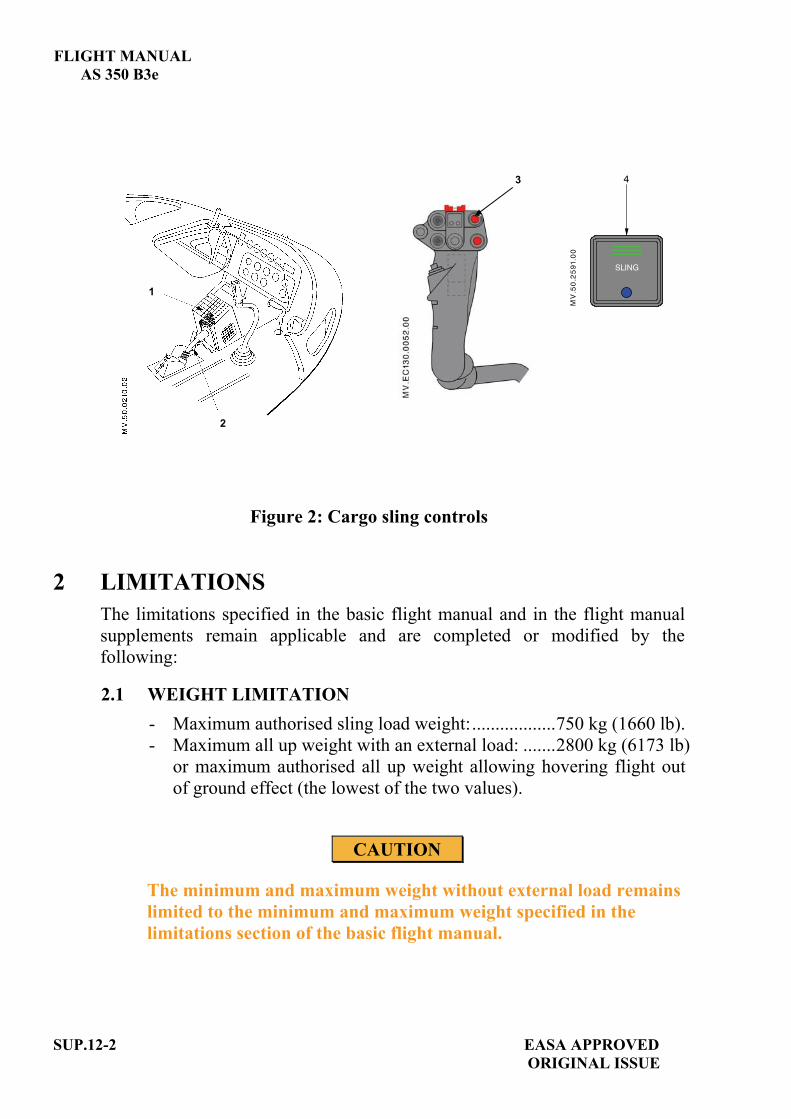
FLIGHT MANUAL AS 350 B3e
3
1
2
Figure 2: Cargo sling controls
2 LIMITATIONS The limitations specified in the basic flight manual and in the flight manual supplements remain applicable and are completed or modified by the following:
2.1 WEIGHT LIMITATION - Maximum authorised sling load weight:..................750 kg (1660 lb). - Maximum all up weight with an external load: .......2800 kg (6173 lb)
or maximum authorised all up weight allowing hovering flight out of ground effect (the lowest of the two values).
CAUTION
The minimum and maximum weight without external load remains limited to the minimum and maximum weight specified in the limitations section of the basic flight manual.
SUP.12-2 EASA APPROVEDORIGINAL ISSUE

FLIGHT MANUAL AS 350 B3e
EASA APPROVED ORIGINAL ISSUE
SUP.12-3
2.2 LONGITUDINAL CG With an external load, the longitudinal limits are defined according to the weight as per the graph below.
2.3 AIRSPEED LIMITATION - Absolute maximum permissible
indicated airspeed with external load ................. 80 kt (148 km/h).
NOTE The pilot is responsible for determining the limit speed according to the load and sling length. Particular care must be exercised when bulkyloads are carried on the sling.
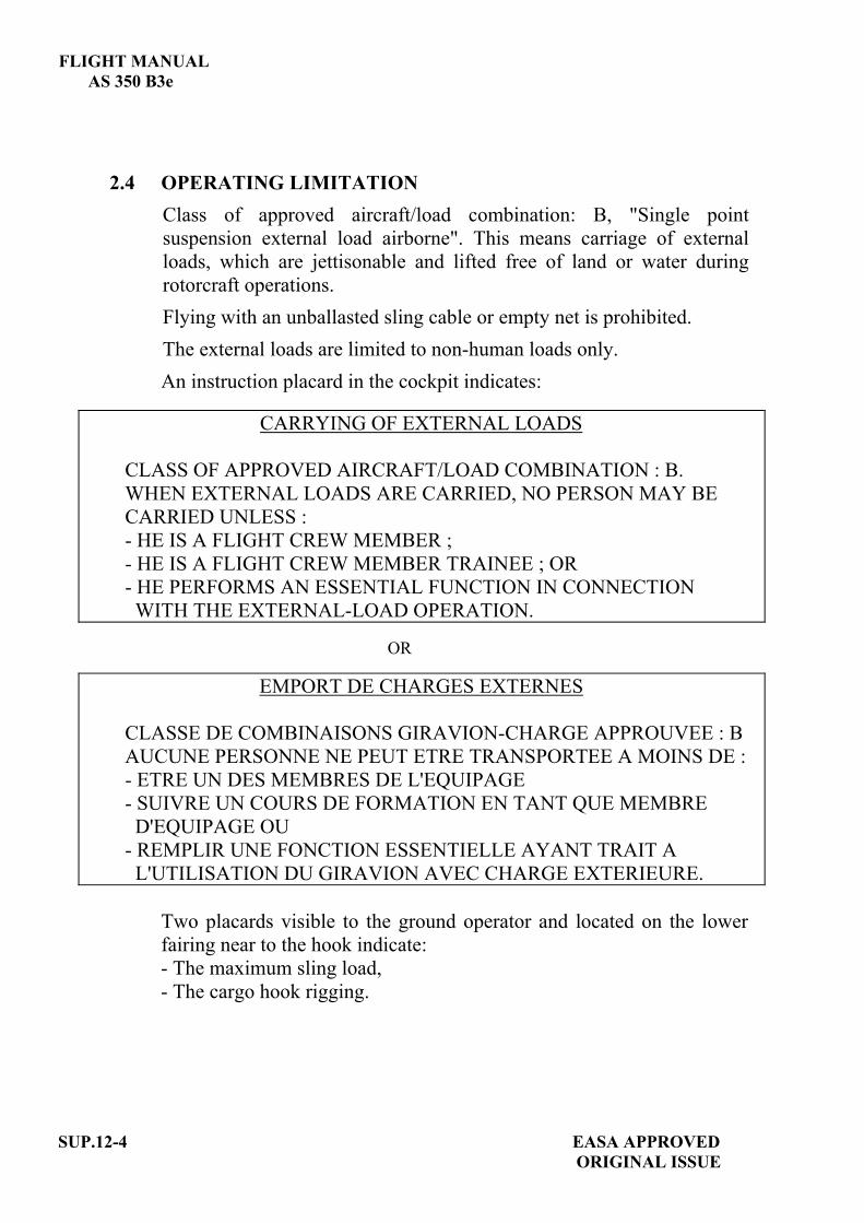
FLIGHT MANUAL AS 350 B3e
2.4 OPERATING LIMITATION Class of approved aircraft/load combination: B, "Single point suspension external load airborne". This means carriage of external loads, which are jettisonable and lifted free of land or water during rotorcraft operations. Flying with an unballasted sling cable or empty net is prohibited. The external loads are limited to non-human loads only. An instruction placard in the cockpit indicates:
CARRYING OF EXTERNAL LOADS
CLASS OF APPROVED AIRCRAFT/LOAD COMBINATION : B. WHEN EXTERNAL LOADS ARE CARRIED, NO PERSON MAY BE CARRIED UNLESS : - HE IS A FLIGHT CREW MEMBER ; - HE IS A FLIGHT CREW MEMBER TRAINEE ; OR - HE PERFORMS AN ESSENTIAL FUNCTION IN CONNECTION WITH THE EXTERNAL-LOAD OPERATION.
OR
EMPORT DE CHARGES EXTERNES
CLASSE DE COMBINAISONS GIRAVION-CHARGE APPROUVEE : B AUCUNE PERSONNE NE PEUT ETRE TRANSPORTEE A MOINS DE :- ETRE UN DES MEMBRES DE L'EQUIPAGE - SUIVRE UN COURS DE FORMATION EN TANT QUE MEMBRE D'EQUIPAGE OU - REMPLIR UNE FONCTION ESSENTIELLE AYANT TRAIT A L'UTILISATION DU GIRAVION AVEC CHARGE EXTERIEURE.
Two placards visible to the ground operator and located on the lower fairing near to the hook indicate: - The maximum sling load,
- The cargo hook rigging.
SUP.12-4 EASA APPROVEDORIGINAL ISSUE

FLIGHT MANUAL AS 350 B3e
EASA APPROVED SUP.12-5 ORIGINAL ISSUE
Figure 3: Cargo hook rigging placard
3 EMERGENCY PROCEDURES The emergency procedures specified in the basic flight manual and in the flight manual supplements remain applicable and are completed or modified by the following: 3.1 ENGINE FAILURE WITH EXTERNAL LOAD
- IN CRUISE FLIGHT 1. Autorotation procedure .................. APPLY. 2. External load .................................. RELEASE as soon as possible.
- IN HOVER 1. Collective pitch. ............................. REDUCE according to the height. 2. External load .................................. RELEASE as soon as possible. 3. Pedals ............................................. Control yaw. 4. Cyclic ............................................. Forward to gain forward speed according to the height. 5. Collective pitch .............................. INCREASE as needed to cushion touch-down.
NOTE In case of a failure during the hooking phase, the pilot shall move the aircraft away to the right. Ground personnel are to be forewarned that in the event of an engine failure they have to move away to the left of the helicopter.
3.2 ELECTRICAL LOAD JETTISONING FAILURE Collective pitch mechanical release ......... ACTUATE

FLIGHT MANUAL AS 350 B3e
4 NORMAL PROCEDURES The normal procedures specified in the basic flight manual and in the flight manual supplements remain applicable and are completed or modified by the following:- Carrying heavy loads is a delicate operation due to the possible effects of a
swinging load on the flight behavior of the helicopter. Consequently, pilots are advised to train with gradually increasing sling loads before undertaking heavy or bulky load carrying operations.
- The length of the sling cable must be determined in accordance with the type of mission. To carry a compact load, it is recommended to use the shortest possible cable.
CAUTIONFlying with an unballasted sling cable or empty net is prohibited.
- For permissible load attachment ring size refer to the "Operational Tips" section of this Flight Manual.
WARNINGTHE USE OF A LOAD ATTACHMENT RING WITH INCORRECT DIMENSIONS MAY LEAD TO LOSS OR JAMMING OF THE LOAD.
WARNINGIN WET WEATHER, THE OPERATORS HANDLING THE HOOK AND LOADS SHOULD WEAR THICK RUBBER GLOVES. DISCHARGE STATIC ELECTRICITY BY PLACING AN ELECTRICAL CONDUCTOR CABLE OR TUBE BETWEEN THE GROUND AND THE CARGO RELEASE UNIT (HOOK).
4.1 CHECK OF THE INSTALLATION
. [SLING] ...........................................................................ON.
. Load indicator .................................................................ZERO.
. Correct opening of the hook (both in electrical and mechanical control modes).......................CHECK.. Rotation of the retaining latch ........................................FREE. . Operation of the retaining latch return spring ................CHECK.
SUP.12-6 EASA APPROVEDORIGINAL ISSUE

FLIGHT MANUAL
AS 350 B3e
4.2 TAKE OFF CHECK AND PROCEDURE WITH EXTERNAL LOAD 1. External load ............................... HOOK and SECURE. 2. Collective .................................... Increase very smoothly while
maintaining the aircraft vertically above the load.
3. Cables tightened.......................... Dwell briefly before raising the load. 4. Lift the load ................................. Vertically. 5. Load indication ........................... CHECK. 6. Take-off path............................... ADJUST to adopt an immediate
forward climb attitude. 7. All parameters ............................. CHECK.
4.3 MANEUVERS All control movements should be made very smoothly, with very gradual acceleration and deceleration, and only slightly banked turns.
4.4 APPROACH AND LANDING WITH EXTERNAL LOAD Perform approach at minimum rate of descent. - Establish zero translational ground speed sufficiently high to ensure that
the load is not dragged along the ground. - Then descend vertically until the load is set on the ground. - Load ............................................... RELEASE.- Load release ................................... CHECK.- All parameters................................ CHECK.
NOTE If the load is not released, actuate the mechanical release handle.
EASA APPROVED SUP.12-7ORIGINAL ISSUE

FLIGHT MANUAL AS 350 B3e
0B5 PERFORMANCE When no external load is carried on the hook, the performance data specified in the basic flight manual and in the flight manual supplements remain applicable. - Hover out of ground effect performance is shown in figure 5-6 of the basic
flight manual. - Hover and climb performance may be affected when carrying bulky loads.
SUP.12-8 EASA APPROVEDORIGINAL ISSUE
EASA APPROVED ORIGINAL ISSUE
SUP.13-TITLE
FLIGHT MANUAL
AS 350 B3e
SUPPLEMENT
EXTERNAL LOAD TRANSPORT “CARGO SWING”
1400 kg (3086 lb) with “SIREN” release unit
(P/N AS21-5-7)
IMPORTANT NOTE
THE INFORMATION CONTAINED HEREIN SUPPLEMENTS OR SUPERSEDES THE INFORMATION GIVEN IN THE BASIC FLIGHT MANUAL AND/OR THE SUPPLEMENTS LISTED IN SECTION SUP.0.
THE EFFECTIVITY OF THE SUPPLEMENT AT THE LATEST REVISION IS SPECIFIED ON THE LIST OF EFFECTIVE PAGES.
THIS SUPPLEMENT MUST BE INCLUDED IN THE FLIGHT MANUAL WHEN THE EQUIPMENT MENTIONED ABOVE IS INSTALLED ON THE AIRCRAFT.
E U R O C O P T E R D i r e c t i o n T e c h n i q u e S u p p o r t Aéroport international Marseille-Provence 13725 Marignane Cedex – France

FLIGHT MANUAL AS 350 B3e
EASA APPROVED AORIGINAL ISSUE
SUP.13-A
LIST OF APPROVED EFFECTIVE PAGES - EASA CERTIFICATION REMARKS / EFFECTIVITY column:
Without indication ......Applicable to all aircraft. Clear text definition ...Effectivity (specified model or variant type ...), information
... A : Specific to EASA.
...S/N nnnn: Specific to S/N nnnn.
PAGE REVNo.
REMARKS / EFFECTIVITY PAGE REV
No.REMARKS /
EFFECTIVITYSUP.13-Title 0
SUP.13-A 0 A
SUP.13-B 0 A
SUP.13-1 0
SUP.13-2 0
SUP.13-3 0
SUP.13-4 0
SUP.13-5 0
SUP.13-6 0
SUP.13-7 0
SUP.13-8 0
SUP.13-9 0

FLIGHT MANUAL
AS 350 B3e
SUP.13-B A
EASA APPROVEDORIGINAL ISSUE
LOG OF APPROVED NORMAL REVISIONS BASIC RFM REVISIONS - EFFECTIVITY EASA
NORMAL REVISION 0 - DECEMBER 2010 EASA approval No. 10035374 on June 17, 2011
Title New flight manual. Revised
information All pages.
Deleted information None
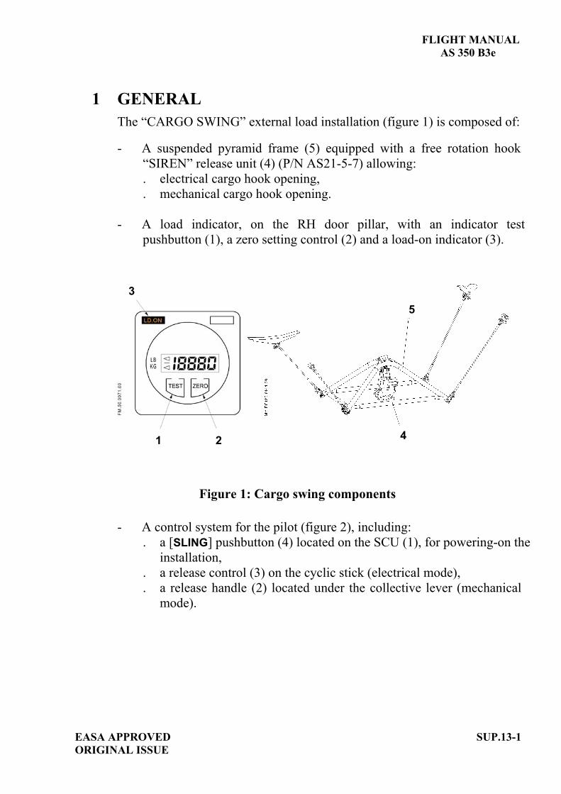
FLIGHT MANUAL AS 350 B3e
EASA APPROVED ORIGINAL ISSUE
SUP.13-1
1 GENERAL The “CARGO SWING” external load installation (figure 1) is composed of:
- A suspended pyramid frame (5) equipped with a free rotation hook “SIREN” release unit (4) (P/N AS21-5-7) allowing:. electrical cargo hook opening, . mechanical cargo hook opening.
- A load indicator, on the RH door pillar, with an indicator test pushbutton (1), a zero setting control (2) and a load-on indicator (3).
1 2
35
4
Figure 1: Cargo swing components
- A control system for the pilot (figure 2), including:. a [SLING] pushbutton (4) located on the SCU (1), for powering-on the
installation,. a release control (3) on the cyclic stick (electrical mode), . a release handle (2) located under the collective lever (mechanical
mode).

FLIGHT MANUAL AS 350 B3e
SUP.13-2 EASA APPROVEDORIGINAL ISSUE
3
2
1
Figure 2: Cargo swing controls
2 LIMITATIONS The limitations specified in the basic flight manual and in the flight manual supplements remain applicable and are completed or modified by the following:2.1 WEIGHT LIMITATION
- Maximum authorized swing load weight:................1400 kg (3086 lb). - Maximum all up weight with an external load: .......2800 kg (6173 lb)
or maximum authorized all up weight allowing hovering flight out of ground effect (the lowest of the two values).
CAUTION
The minimum and maximum weight without external load remains limited to the minimum and maximum weight specified in the limitations section of the basic flight manual.

FLIGHT MANUAL AS 350 B3e
EASA APPROVED ORIGINAL ISSUE
SUP.13-3
2.2 LONGITUDINAL CG With an external load, the longitudinal limits are defined according to the weight as per the graph below.
2.3 AIRSPEED LIMITATION - Absolute maximum permissible
indicated airspeed with external load ................. 80 kt (148 km/h).
NOTE The pilot is responsible for determining the limit speed according to the load and sling length. Particular care must be exercised when bulkyloads are carried on the sling.

FLIGHT MANUAL AS 350 B3e
SUP.13-4 EASA APPROVEDORIGINAL ISSUE
2.4 OPERATING LIMITATION Class of approved aircraft/load combination: B, "Single point suspension external load airborne". This means carriage of external loads, which arejettisonable and lifted free of land or water during rotorcraft operations. Flying with an unballasted sling cable or empty net is prohibited. The external loads are limited to non-human loads only. An instruction placard in the cockpit indicates:
CARRYING OF EXTERNAL LOADS
CLASS OF APPROVED AIRCRAFT/LOAD COMBINATION: B. WHEN EXTERNAL LOADS ARE CARRIED, NO PERSON MAY BE CARRIED UNLESS:- HE IS A FLIGHT CREW MEMBER;- HE IS A FLIGHT CREW MEMBER TRAINEE; OR- HE PERFORMS AN ESSENTIAL FUNCTION IN CONNECTION WITH THE EXTERNAL-LOAD OPERATION.
OR
EMPORT DE CHARGES EXTERNES
CLASSE DE COMBINAISONS GIRAVION-CHARGE APPROUVEE : B AUCUNE PERSONNE NE PEUT ETRE TRANSPORTEE A MOINS DE :- ETRE UN DES MEMBRES DE L'EQUIPAGE - SUIVRE UN COURS DE FORMATION EN TANT QUE MEMBRE D'EQUIPAGE OU
- REMPLIR UNE FONCTION ESSENTIELLE AYANT TRAIT A L'UTILISATION DU GIRAVION AVEC CHARGE EXTERIEURE.
Two placards visible to the ground operator and located on the lower fairing near to the hook indicate: - The maximum sling load, - The cargo hook rigging.

FLIGHT MANUAL AS 350 B3e
EASA APPROVED ORIGINAL ISSUE
SUP.13-5
Figure 3: Cargo hook rigging placard
3 EMERGENCY PROCEDURES The emergency procedures specified in the basic flight manual and in the flight manual supplements remain applicable and are completed or modified by the following: 3.1 ENGINE FAILURE WITH EXTERNAL LOAD
- IN CRUISE FLIGHT 1. Autorotation procedure ................... APPLY.2. External load ................................... RELEASE as soon as possible.
- IN HOVER 1. Collective pitch. .............................. REDUCE according to the height. 2. External load ................................... RELEASE as soon as possible. 3. Pedals .............................................. CONTROL yaw. 4. Cyclic .............................................. FORWARD to gain forward
.......................................................... speed according to the height. 5. Collective pitch ............................... INCREASE as needed to cushion touch-down.
NOTEIn case of a failure during the hooking phase, the pilot shall move the aircraft away to the right. Ground personnel are to be forewarned that in the event of an engine failure they have to move away to the left of the helicopter.
3.2 ELECTRICAL LOAD JETTISONING FAILURE Collective pitch mechanical release ...... ACTUATE

FLIGHT MANUAL AS 350 B3e
SUP.13-6 EASA APPROVEDORIGINAL ISSUE
3.3 LOAD INDICATOR FAILURE If the LD ON light comes on or goes out in an untimely manner: - IN HOVER, during hooking or unhooking phase: - Load...........................................RELEASE through electrical control. - LD ON ......................................CHECK light status.
NO CHANGE STATUS CHANGE
ABORT MISSION CONTINUE FLIGHT
- IN CRUISE FLIGHT Perform a precautionary approach on the nearest helipad, then apply previous "IN HOVER" procedure.
4 NORMAL PROCEDURES The normal procedures specified in the basic flight manual and in the flight manual supplements remain applicable and are completed or modified by the following:- Carrying heavy loads is a delicate operation due to the possible effects of a
swinging load on the flight behavior of the helicopter. Consequently, pilots are advised to train with gradually increasing sling loads before undertaking heavy or bulky load carrying operations.
- The length of the sling cable must be determined in accordance with the type of mission. To carry a compact load, it is recommended to use the shortest possible cable.
CAUTIONFlying with an unballasted sling cable or empty net is prohibited.
- For permissible load attachment ring size refer to the "Operational Tips" section of this flight manual.
WARNINGTHE USE OF A LOAD ATTACHMENT RING WITH INCORRECT DIMENSIONS MAY LEAD TO LOSS OR JAMMING OF THE LOAD.

FLIGHT MANUAL AS 350 B3e
EASA APPROVED ORIGINAL ISSUE
SUP.13-7
WARNING
IN WET WEATHER, THE OPERATORS HANDLING THE HOOK AND LOADS SHOULD WEAR THICK RUBBER GLOVES. DISCHARGE STATIC ELECTRICITY BY PLACING AN ELECTRICAL CONDUCTOR CABLE OR TUBE BETWEEN THE GROUND AND THE CARGO RELEASE UNIT (HOOK).
4.1 CHECK OF THE INSTALLATION - [SLING] .............................................................ON, On the load indicator:- LD ON .............................................................CHECK LD ON ,- [ZERO] ..............................................................PRESS, 0 is displayed, - [TEST] ...............................................................PRESS,
The test sequence is started; each display lasts for about 3 sec., followed by no display for approx. 3 sec. . display of : . display of the "calibration" value. This value should be the same as
the one engraved on the transmitter fitted between the helicopter and the hook.
. display of ZERO offset (this value is the total offset which has been previously tared out by use of [ZERO]).
. display of two values separated by a dash: the first value, between 0 and 3, shows the filter selected and the second value shows the logic programmed in the computer.
Cargo swing check: - Correct opening of the hook (both in
electrical and mechanical control modes) ........CHECK,- Rotation of the retaining latch ..........................FREE,- Operation of the
retaining latch return spring..............................CHECK.

FLIGHT MANUAL AS 350 B3e
SUP.13-8 EASA APPROVEDORIGINAL ISSUE
4.2 TAKEOFF CHECK AND PROCEDURE WITH EXTERNAL LOAD1. External load.................................. HOOK AND SECURE.2. Collective....................................... INCREASE very smoothly
while maintaining the aircraft vertically above the load.
3. Cables tightened ............................ Dwell briefly before raising the load.
4. Lift the load.................................... Vertically. 5. Load indication .............................. CHECK LD ON .6. Take-off path ................................. ADJUST to adopt an immediate
forward climb attitude.7. All parameters................................ CHECK.
4.3 MANEUVERSAll control movements should be made very gently, with very gradual acceleration and deceleration, and only slightly banked turns.
4.4 APPROACH AND LANDING WITH EXTERNAL LOAD
- Perform approach at minimum rate of descent. - Establish zero translational ground speed sufficiently high to ensure
that the load is not dragged along the ground. - Then descend vertically until the load is on the ground. - Load.................................................. RELEASE. - Effective load release ....................... CHECK LD ON .- All parameters .................................. CHECK.
NOTE If the load is not released, actuate the mechanical release handle.

FLIGHT MANUAL AS 350 B3e
EASA APPROVED ORIGINAL ISSUE
SUP.13-9
5 PERFORMANCE When no external load is carried on the hook, the performance data specified in the basic flight manual and in the flight manual supplements remain applicable.- Hover out of ground effect performance is shown in Figure 5-6 of the basic
flight manual.- Hover and climb performance may be affected when carrying bulky loads.


EASA APPROVED ORIGINAL ISSUE
SUP.13.1-TITLE
FLIGHT MANUAL
AS 350 B3e
SUPPLEMENT
EXTERNAL LOAD TRANSPORT “CARGO SWING”
1400 kg (3086 lb) with “SIREN” fixed release unit
(P/N S1609)
IMPORTANT NOTE
THE INFORMATION CONTAINED HEREIN SUPPLEMENTS OR SUPERSEDES THE INFORMATION GIVEN IN THE BASIC FLIGHT MANUAL AND/OR THE SUPPLEMENTS LISTED IN SECTION SUP.0.
THE EFFECTIVITY OF THE SUPPLEMENT AT THE LATEST REVISION IS SPECIFIED ON THE LIST OF EFFECTIVE PAGES.
THIS SUPPLEMENT MUST BE INCLUDED IN THE FLIGHT MANUAL WHEN THE EQUIPMENT MENTIONED ABOVE IS INSTALLED ON THE AIRCRAFT.
E U R O C O P T E R D i r e c t i o n T e c h n i q u e S u p p o r t Aéroport international Marseille-Provence 13725 Marignane Cedex – France

FLIGHT MANUAL AS 350 B3e
EASA APPROVED AORIGINAL ISSUE
SUP.13.1-A
LIST OF APPROVED EFFECTIVE PAGES - EASA CERTIFICATION REMARKS / EFFECTIVITY column:
Without indication ......Applicable to all aircraft. Clear text definition ...Effectivity (specified model or variant type ...), information
... A : Specific to EASA.
...S/N nnnn: Specific to S/N nnnn.
PAGE REVNo.
REMARKS / EFFECTIVITY PAGE REV
No.REMARKS /
EFFECTIVITYSUP.13.1-Title 0
SUP.13.1-A 0 A
SUP.13.1-B 0 A
SUP.13.1-1 0
SUP.13.1-2 0
SUP.13.1-3 0
SUP.13.1-4 0
SUP.13.1-5 0
SUP.13.1-6 0
SUP.13.1-7 0
SUP.13.1-8 0
SUP.13.1-9 0

FLIGHT MANUAL
AS 350 B3e
SUP.13.1-B A
EASA APPROVEDORIGINAL ISSUE
LOG OF APPROVED NORMAL REVISIONS BASIC RFM REVISIONS - EFFECTIVITY EASA
NORMAL REVISION 0 - DECEMBER 2010 EASA approval No. 10035374 on June 17, 2011
Title New flight manual. Revised
information All pages.
Deleted information None

m FLIGHT MANUAL AS 350 B3e
EASA APPROVED ORIGINAL ISSUE
SUP.13.1-1
1 GENERAL The “CARGO SWING” external load installation (figure 1) is composed of:
- A suspended pyramid frame (5) equipped with a fixed rotation hook “SIREN” release unit (4) (P/N S1609) allowing:. electrical cargo hook opening, . mechanical cargo hook opening.
- A load indicator, on the RH door pillar, with an indicator test pushbutton (1), a zero setting control (2) and a load-on indicator (3).
1 2
3
5
4
Figure 1: Cargo swing components
- A control system for the pilot (figure 2), including:. a [SLING] pushbutton (4) located on the SCU (1), for powering-on the
installation,. a release control (3) on the cyclic stick (electrical mode), . a release handle (2) located under the collective lever (mechanical
mode).

FLIGHT MANUAL AS 350 B3e
SUP.13.1-2 EASA APPROVEDORIGINAL ISSUE
3
2
1
Figure 2: Cargo swing controls
2 LIMITATIONS The limitations specified in the basic flight manual and in the flight manual supplements remain applicable and are completed or modified by the following:2.1 WEIGHT LIMITATION
- Maximum authorized swing load weight:................1400 kg (3086 lb). - Maximum all up weight with an external load: .......2800 kg (6173 lb)
or maximum authorized all up weight allowing hovering flight out of ground effect (the lowest of the two values).
CAUTION
The minimum and maximum weight without external load remains limited to the minimum and maximum weight specified in the limitations section of the basic flight manual.

FLIGHT MANUAL AS 350 B3e
EASA APPROVED ORIGINAL ISSUE
SUP.13.1-3
2.2 LONGITUDINAL CG With an external load, the longitudinal limits are defined according to the weight as per the graph below.
2.3 AIRSPEED LIMITATION - Absolute maximum permissible
indicated airspeed with external load ................. 80 kt (148 km/h).
NOTE The pilot is responsible for determining the limit speed according to the load and sling length. Particular care must be exercised when bulkyloads are carried on the sling.

FLIGHT MANUAL AS 350 B3e
SUP.13.1-4 EASA APPROVEDORIGINAL ISSUE
2.4 OPERATING LIMITATION Class of approved aircraft/load combination: B, "Single point suspension external load airborne". This means carriage of external loads, which arejettisonable and lifted free of land or water during rotorcraft operations. Flying with an unballasted sling cable or empty net is prohibited. The external loads are limited to non-human loads only. An instruction placard in the cockpit indicates:
CARRYING OF EXTERNAL LOADS
CLASS OF APPROVED AIRCRAFT/LOAD COMBINATION: B. WHEN EXTERNAL LOADS ARE CARRIED, NO PERSON MAY BE CARRIED UNLESS:- HE IS A FLIGHT CREW MEMBER;- HE IS A FLIGHT CREW MEMBER TRAINEE; OR- HE PERFORMS AN ESSENTIAL FUNCTION IN CONNECTION WITH THE EXTERNAL-LOAD OPERATION.
OR
EMPORT DE CHARGES EXTERNES
CLASSE DE COMBINAISONS GIRAVION-CHARGE APPROUVEE : B AUCUNE PERSONNE NE PEUT ETRE TRANSPORTEE A MOINS DE :- ETRE UN DES MEMBRES DE L'EQUIPAGE - SUIVRE UN COURS DE FORMATION EN TANT QUE MEMBRE D'EQUIPAGE OU
- REMPLIR UNE FONCTION ESSENTIELLE AYANT TRAIT A L'UTILISATION DU GIRAVION AVEC CHARGE EXTERIEURE.
Two placards visible to the ground operator and located on the lower fairing near to the hook indicate: - The maximum sling load, - The cargo hook rigging.
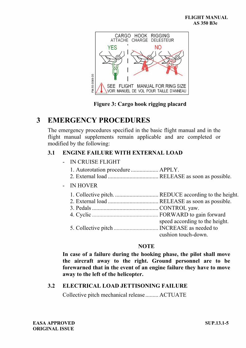
FLIGHT MANUAL AS 350 B3e
EASA APPROVED ORIGINAL ISSUE
SUP.13.1-5
Figure 3: Cargo hook rigging placard
3 EMERGENCY PROCEDURES The emergency procedures specified in the basic flight manual and in the flight manual supplements remain applicable and are completed or modified by the following: 3.1 ENGINE FAILURE WITH EXTERNAL LOAD
- IN CRUISE FLIGHT 1. Autorotation procedure ................... APPLY.2. External load ................................... RELEASE as soon as possible.
- IN HOVER 1. Collective pitch. .............................. REDUCE according to the height. 2. External load ................................... RELEASE as soon as possible. 3. Pedals .............................................. CONTROL yaw. 4. Cyclic .............................................. FORWARD to gain forward
.......................................................... speed according to the height. 5. Collective pitch ............................... INCREASE as needed to cushion touch-down.
NOTEIn case of a failure during the hooking phase, the pilot shall movethe aircraft away to the right. Ground personnel are to be forewarned that in the event of an engine failure they have to move away to the left of the helicopter.
3.2 ELECTRICAL LOAD JETTISONING FAILURE Collective pitch mechanical release ......... ACTUATE
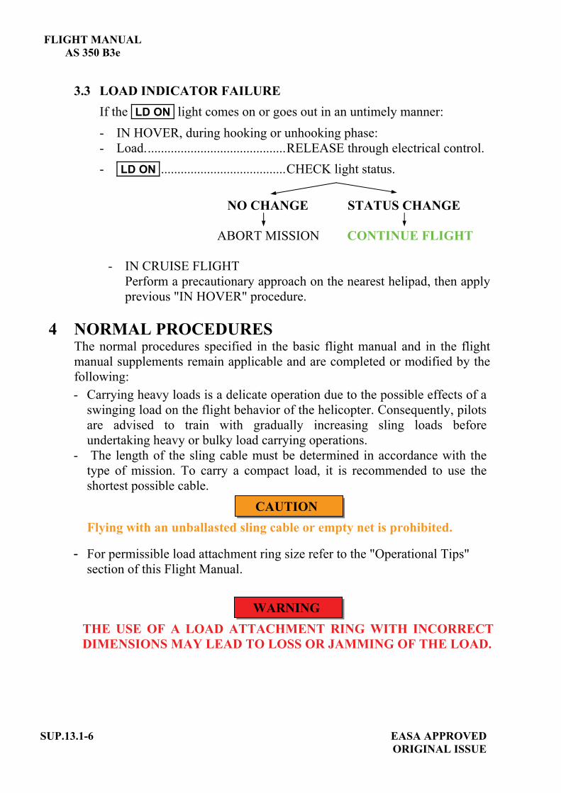
FLIGHT MANUAL AS 350 B3e
SUP.13.1-6 EASA APPROVEDORIGINAL ISSUE
3.3 LOAD INDICATOR FAILURE If the LD ON light comes on or goes out in an untimely manner: - IN HOVER, during hooking or unhooking phase: - Load...........................................RELEASE through electrical control. - LD ON ......................................CHECK light status.
NO CHANGE STATUS CHANGE
ABORT MISSION CONTINUE FLIGHT
- IN CRUISE FLIGHT Perform a precautionary approach on the nearest helipad, then apply previous "IN HOVER" procedure.
4 NORMAL PROCEDURES The normal procedures specified in the basic flight manual and in the flight manual supplements remain applicable and are completed or modified by the following:- Carrying heavy loads is a delicate operation due to the possible effects of a
swinging load on the flight behavior of the helicopter. Consequently, pilots are advised to train with gradually increasing sling loads before undertaking heavy or bulky load carrying operations.
- The length of the sling cable must be determined in accordance with the type of mission. To carry a compact load, it is recommended to use the shortest possible cable.
CAUTIONFlying with an unballasted sling cable or empty net is prohibited.
- For permissible load attachment ring size refer to the "Operational Tips" section of this Flight Manual.
WARNINGTHE USE OF A LOAD ATTACHMENT RING WITH INCORRECT DIMENSIONS MAY LEAD TO LOSS OR JAMMING OF THE LOAD.

FLIGHT MANUAL AS 350 B3e
EASA APPROVED ORIGINAL ISSUE
SUP.13.1-7
WARNING
IN WET WEATHER, THE OPERATORS HANDLING THE HOOK AND LOADS SHOULD WEAR THICK RUBBER GLOVES. DISCHARGE STATIC ELECTRICITY BY PLACING AN ELECTRICAL CONDUCTOR CABLE OR TUBE BETWEEN THE GROUND AND THE CARGO RELEASE UNIT (HOOK).
4.1 CHECK OF THE INSTALLATION - [SLING] .............................................................ON. On the load indicator: - LD ON .............................................................CHECK LD ON .- [ZERO] ..............................................................PRESS, 0 is displayed. - [TEST] ...............................................................PRESS.
The test sequence is started; each display lasts for about 3 sec., followed by no display for approx. 3 sec. . display of : . display of the "calibration" value. This value should be the same as
the one engraved on the transmitter fitted between the helicopter and the hook.
. display of ZERO offset (this value is the total offset which has been previously tared out by use of [ZERO]).
. display of two values separated by a dash: the first value, between 0 and 3, shows the filter selected and the second value shows the logic programmed in the computer.
Cargo swing check: - Correct opening of the hook (both in
electrical and mechanical control modes) ........CHECK.- Rotation of the retaining latch ..........................FREE.- Operation of the
retaining latch return spring..............................CHECK.

FLIGHT MANUAL AS 350 B3e
SUP.13.1-8 EASA APPROVEDORIGINAL ISSUE
4.2 TAKEOFF CHECK AND PROCEDURE WITH EXTERNAL LOAD1. External load.................................. HOOK AND SECURE.2. Collective....................................... INCREASE very smoothly
while maintaining the aircraft vertically above the load.
3. Cables tightened ............................ Dwell briefly before raising the load.
4. Lift the load.................................... Vertically. 5. Load indication .............................. CHECK LD ON .6. Take-off path ................................. ADJUST to adopt an immediate
forward climb attitude.7. All parameters................................ CHECK.
4.3 MANEUVERSAll control movements should be made very gently, with very gradual acceleration and deceleration, and only slightly banked turns.
4.4 APPROACH AND LANDING WITH EXTERNAL LOAD
- Perform approach at minimum rate of descent. - Establish zero translational ground speed sufficiently high to ensure
that the load is not dragged along the ground. - Then descend vertically until the load is on the ground. - Load.................................................. RELEASE. - Effective load release ....................... CHECK LD ON .- All parameters .................................. CHECK.
NOTE If the load is not released, actuate the mechanical release handle.

FLIGHT MANUAL AS 350 B3e
EASA APPROVED ORIGINAL ISSUE
SUP.13.1-9
5 PERFORMANCE When no external load is carried on the hook, the performance data specified in the basic flight manual and in the flight manual supplements remain applicable.- Hover out of ground effect performance is shown in Figure 5-6 of the
basic flight manual. - Hover and climb performance may be affected when carrying bulky loads.


EASA APPROVED ORIGINAL ISSUE
SUP.13.2-TITLE
FLIGHT MANUAL
AS 350 B3e
SUPPLEMENT
EXTERNAL LOAD TRANSPORT “CARGO SWING”
1400 kg (3086 lb) with “ON-BOARD” release unit
(P/N 528-023-51)
IMPORTANT NOTE
THE INFORMATION CONTAINED HEREIN SUPPLEMENTS OR SUPERSEDES THE INFORMATION GIVEN IN THE BASIC FLIGHT MANUAL AND/OR THE SUPPLEMENTS LISTED IN SECTION SUP.0.
THE EFFECTIVITY OF THE SUPPLEMENT AT THE LATEST REVISION IS SPECIFIED ON THE LIST OF EFFECTIVE PAGES.
THIS SUPPLEMENT MUST BE INCLUDED IN THE FLIGHT MANUAL WHEN THE EQUIPMENT MENTIONED ABOVE IS INSTALLED ON THE AIRCRAFT.
E U R O C O P T E R D i r e c t i o n T e c h n i q u e S u p p o r t Aéroport international Marseille-Provence 13725 Marignane Cedex – France


FLIGHT MANUAL AS 350 B3e
EASA APPROVED AORIGINAL ISSUE
SUP.13.2-A
LIST OF APPROVED EFFECTIVE PAGES - EASA CERTIFICATION REMARKS / EFFECTIVITY column:
Without indication ......Applicable to all aircraft. Clear text definition ...Effectivity (specified model or variant type ...), information
... A : Specific to EASA.
...S/N nnnn: Specific to S/N nnnn.
PAGE REVNo.
REMARKS / EFFECTIVITY PAGE REV
No.REMARKS /
EFFECTIVITYSUP.13.2-Title 0
SUP.13.2-A 0 A
SUP.13.2-B 0 A
SUP.13.2-1 0
SUP.13.2-2 0
SUP.13.2-3 0
SUP.13.2-4 0
SUP.13.2-5 0
SUP.13.2-6 0
SUP.13.2-7 0
SUP.13.2-8 0

FLIGHT MANUAL
AS 350 B3e
SUP.13.2-B A
EASA APPROVEDORIGINAL ISSUE
LOG OF APPROVED NORMAL REVISIONS BASIC RFM REVISIONS - EFFECTIVITY EASA
NORMAL REVISION 0 - DECEMBER 2010 EASA approval No. 10035374 on June 17, 2011
Title New flight manual. Revised
information All pages.
Deleted information None

FLIGHT MANUAL AS 350 B3e
EASA APPROVED ORIGINAL ISSUE
SUP13.2-1
1 GENERAL The “CARGO SWING” external load installation (figure 1) is composed of:
- A suspended pyramid frame (6) held by two elastic straps (7) equippedwith a bumper ring (P/N: 232-155-00) (5) and an “ON-BOARD” release unit (P/N 528-023-51) (4) allowing:. electrical cargo hook opening, . mechanical cargo hook opening.
- A load indicator, on the RH door pillar, with an indicator test pushbutton(1), a zero setting control (2) and a display window (3).
6
5
4
73
1 2
Figure 1: Cargo swing components
- A control system for the pilot (figure 2), including:. a [SLING] pushbutton (4) located on the SCU (1), for powering-on the
installation,. a release control (3) on the cyclic stick (electrical mode), . a release handle (2) located under the collective lever (mechanical
mode).

FLIGHT MANUAL AS 350 B3e
SUP.13.2-2 EASA APPROVEDORIGINAL ISSUE
3
1
2
Figure 2: Cargo swing controls
2 LIMITATIONS The limitations specified in the basic flight manual and in the flight manual supplements remain applicable and are completed or modified by the following:2.1 WEIGHT LIMITATION
- Maximum authorized swing load weight:................1400 kg (3086 lb). - Maximum all up weight with an external load: .......2800 kg (6173 lb) or
maximum authorized all up weight allowing hovering flight out of ground effect (the lowest of the two values).
CAUTION
The minimum and maximum weight without external load remains limited to the minimum and maximum weight specified in the limitations section of the basic flight manual.
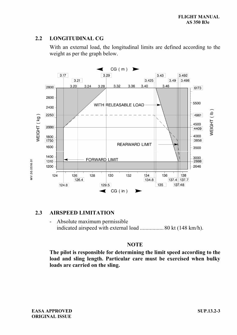
FLIGHT MANUAL AS 350 B3e
EASA APPROVED ORIGINAL ISSUE
SUP.13.2-3
2.2 LONGITUDINAL CG With an external load, the longitudinal limits are defined according to the weight as per the graph below.
2.3 AIRSPEED LIMITATION - Absolute maximum permissible
indicated airspeed with external load ................. 80 kt (148 km/h).
NOTE The pilot is responsible for determining the limit speed according to the load and sling length. Particular care must be exercised when bulkyloads are carried on the sling.
FLIGHT MANUAL AS 350 B3e
SUP.13.2-4 EASA APPROVEDORIGINAL ISSUE
2.4 OPERATING LIMITATION Class of approved aircraft/load combination: B, "Single point suspension external load airborne". This means carriage of external loads, which arejettisonable and lifted free of land or water during rotorcraft operations. Flying with an unballasted sling cable or empty net is prohibited. The external loads are limited to non-human loads only. An instruction placard in the cockpit indicates:
CARRYING OF EXTERNAL LOADS
CLASS OF APPROVED AIRCRAFT/LOAD COMBINATION: B. WHEN EXTERNAL LOADS ARE CARRIED, NO PERSON MAY BE CARRIED UNLESS:- HE IS A FLIGHT CREW MEMBER;- HE IS A FLIGHT CREW MEMBER TRAINEE; OR- HE PERFORMS AN ESSENTIAL FUNCTION IN CONNECTION WITH THE EXTERNAL-LOAD OPERATION.
OR
EMPORT DE CHARGES EXTERNES
CLASSE DE COMBINAISONS GIRAVION-CHARGE APPROUVEE : B AUCUNE PERSONNE NE PEUT ETRE TRANSPORTEE A MOINS DE :- ETRE UN DES MEMBRES DE L'EQUIPAGE - SUIVRE UN COURS DE FORMATION EN TANT QUE MEMBRE D'EQUIPAGE OU
- REMPLIR UNE FONCTION ESSENTIELLE AYANT TRAIT A L'UTILISATION DU GIRAVION AVEC CHARGE EXTERIEURE.
Two placards visible to the ground operator and located on the lower fairing near to the hook indicate: - The maximum sling load, - The cargo hook rigging.

FLIGHT MANUAL AS 350 B3e
EASA APPROVED ORIGINAL ISSUE
SUP.13.2-5
Figure 3: Cargo hook rigging placard
3 EMERGENCY PROCEDURES The emergency procedures specified in the basic flight manual and in the flight manual supplements remain applicable and are completed or modified by the following: 3.1 ENGINE FAILURE WITH EXTERNAL LOAD
- IN CRUISE FLIGHT 1. Autorotation procedure ................... APPLY.2. External load ................................... RELEASE as soon as possible.
- IN HOVER 1. Collective pitch. .............................. REDUCE according to the height. 2. External load ................................... RELEASE as soon as possible. 3. Pedals .............................................. CONTROL yaw. 4. Cyclic .............................................. FORWARD to gain forward
.......................................................... speed according to the height. 5. Collective pitch ............................... INCREASE as needed to cushion touch-down.
NOTEIn case of a failure during the hooking phase, the pilot shall move the aircraft away to the right. Ground personnel are to be forewarned that in the event of an engine failure they have to move away to the left of the helicopter.
3.2 ELECTRICAL LOAD JETTISONING FAILURE Collective pitch mechanical release ...... ACTUATE

FLIGHT MANUAL AS 350 B3e a
SUP.13.2-6 EASA APPROVEDORIGINAL ISSUE
4 NORMAL PROCEDURES The normal procedures specified in the basic flight manual and in the flight manual supplements remain applicable and are completed or modified by the following: - Carrying heavy loads is a delicate operation due to the possible effects of
a swinging load on the flight behavior of the helicopter. Consequently, pilots are advised to train with gradually increasing sling loads before undertaking heavy or bulky load carrying operations.
- The length of the sling cable must be determined in accordance with the type of mission. To carry a compact load, it is recommended to use the shortest possible cable.
CAUTIONFlying with an unballasted sling cable or empty net is prohibited.
- For permissible load attachment ring size refer to the "Operational Tips" section of this Flight Manual.
WARNINGTHE USE OF A LOAD ATTACHMENT RING WITH INCORRECT DIMENSIONS MAY LEAD TO LOSS OR JAMMING OF THE LOAD.
WARNING
IN WET WEATHER, THE OPERATORS HANDLING THE HOOK AND LOADS SHOULD WEAR THICK RUBBER GLOVES. DISCHARGE STATIC ELECTRICITY BY PLACING AN ELECTRICAL CONDUCTOR CABLE OR TUBE BETWEEN THE GROUND AND THE CARGO RELEASE UNIT (HOOK).
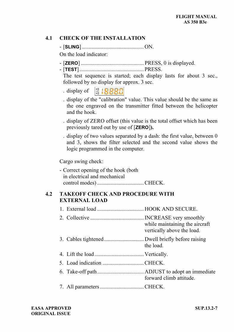
FLIGHT MANUAL AS 350 B3e
EASA APPROVED ORIGINAL ISSUE
SUP.13.2-7
4.1 CHECK OF THE INSTALLATION - [SLING] ............................................. ON. On the load indicator: - [ZERO] .............................................. PRESS, 0 is displayed. - [TEST] ............................................... PRESS.
The test sequence is started; each display lasts for about 3 sec., followed by no display for approx. 3 sec. . display of . display of the "calibration" value. This value should be the same as
the one engraved on the transmitter fitted between the helicopter and the hook.
. display of ZERO offset (this value is the total offset which has been previously tared out by use of [ZERO]).
. display of two values separated by a dash: the first value, between 0 and 3, shows the filter selected and the second value shows the logic programmed in the computer.
Cargo swing check: - Correct opening of the hook (both
in electrical and mechanicalcontrol modes) .................................. CHECK.
4.2 TAKEOFF CHECK AND PROCEDURE WITH EXTERNAL LOAD 1. External load .................................. HOOK AND SECURE.2. Collective ....................................... INCREASE very smoothly
while maintaining the aircraft vertically above the load.
3. Cables tightened............................. Dwell briefly before raising the load.
4. Lift the load .................................... Vertically.5. Load indication .............................. CHECK. 6. Take-off path.................................. ADJUST to adopt an immediate
forward climb attitude.7. All parameters ................................ CHECK.
FLIGHT MANUAL AS 350 B3e
SUP.13.2-8 EASA APPROVEDORIGINAL ISSUE
4.3 MANEUVERSAll control movements should be made very gently, with very gradual acceleration and deceleration, and only slightly banked turns.
4.4 APPROACH AND LANDING WITH EXTERNAL LOAD
- Perform approach at minimum rate of descent. - Establish zero translational ground speed sufficiently high to ensure
that the load is not dragged along the ground. - Then descend vertically until the load is on the ground. - Load.................................................. RELEASE. - Effective load release ....................... CHECK. - All parameters .................................. CHECK.
NOTEIf the load is not released, actuate the mechanical release handle.
5 PERFORMANCE When no external load is carried on the hook, the performance data specified in the basic flight manual and in the flight manual supplements remain applicable. - Hover out of ground effect performance is shown in Figure 5-6 of the
basic flight manual.- Hover and climb performance may be affected when carrying bulky
loads.

EASA APPROVED SUP.14-TITLE ORIGINAL ISSUE
FLIGHT MANUAL
AS 350 B3e
SUPPLEMENT
SAND FILTER Reference: 704A41650014
IMPORTANT NOTE THE INFORMATION CONTAINED HEREIN SUPPLEMENTS OR SUPERSEDES THE INFORMATION GIVEN IN THE BASIC FLIGHT MANUAL AND/OR THE SUPPLEMENTS LISTED IN SECTION SUP.0. THE EFFECTIVITY OF THE SUPPLEMENT AT THE LATEST REVISION IS SPECIFIED ON THE LIST OF EFFECTIVE PAGES.
THIS SUPPLEMENT MUST BE INCLUDED IN THE FLIGHT MANUAL WHEN THE EQUIPMENT MENTIONED ABOVE IS INSTALLED ON THE AIRCRAFT.
E U R O C O P T E R D i r e c t i o n T e c h n i q u e S u p p o r t Aéroport international Marseille-Provence 13725 Marignane Cedex – France


FLIGHT MANUAL AS 350 B3e
EASA APPROVED AORIGINAL ISSUE
SUP.14-A
LIST OF APPROVED EFFECTIVE PAGES - EASA CERTIFICATION REMARKS / EFFECTIVITY column:
Without indication ......Applicable to all aircraft. Clear text definition ...Effectivity (specified model or variant type ...), information
... A : Specific to EASA.
...S/N nnnn: Specific to S/N nnnn.
PAGE REVNo.
REMARKS / EFFECTIVITY PAGE REV
No.REMARKS /
EFFECTIVITYSUP.14-Title 0
SUP.14-A 0 A
SUP.14-B 0 A
SUP.14-1 0
SUP.14-2 0
SUP.14-3 0
SUP.14-4 blank 0
SUP.14-5 0
SUP.14-6 0

FLIGHT MANUAL
AS 350 B3e
SUP.14-B A
EASA APPROVEDORIGINAL ISSUE
LOG OF APPROVED NORMAL REVISIONS BASIC RFM REVISIONS - EFFECTIVITY EASA
NORMAL REVISION 0 - DECEMBER 2010 EASA approval No. 10035374 on June 17, 2011
Title New flight manual. Revised
information All pages.
Deleted information None

FLIGHT MANUAL AS 350 B3e
EASA APPROVED SUP.14-1 ORIGINAL ISSUE
1 GENERAL The sand filter installation is intended to protect the engine from sand ingestion, during hovering flight or when flying in sand-laden atmosphere. This installation is also designed to protect the air intake against any potential ingestion of snow in flight in falling snow. The installation consists essentially of: - A filter fitted on the engine air intake, below the ice protection screen. - A P2 air pressure supply system. - An electrical control and monitoring system. During engine operation, the ambient air flows through separator tubes which constitute the filter. The filtered air is forced towards the engine air intake. The sand is evacuated by scavenge tubes ventilated by P2 air. The electrical circuit supplies an electric valve via [SAND FILT] push-button on the SCU. Opening and closing of the P2 air pressure circuit is controlled by an electric valve. A P 2 m e s s a g e on the FLI display of the VEMD indicates that the electric valve is fully opened. The electrical circuit is protected by the SAND FILT breaker on the console side breaker panel.
2 LIMITATIONS
The limitations specified in the basic flight manual and in the flight manual supplements remain applicable and are completed or modified by the following: - The heating and demisting systems must be switched off when P 2 ON,
- P 2 OFF when visible moisture and OAT < 0°C,
- Flight in falling snow is permitted when P 2 OFF.

FLIGHT MANUAL AS 350 B3e
3 EMERGENCY PROCEDURES The emergency procedures specified in the basic flight manual and in the flight manual supplements remain applicable and are completed or modified by the following:
VEMD CORRECTIVE ACTIONS
P2 Remains off.
The " P2 " air valve fails to open.
Avoid flying the helicopter in sandy atmosphere.
P2 Remains on.
The " P2 " air valve fails to close.
CONTINUE FLIGHT
CAUTION
Observe the limitations given in SECTION 2 of this supplement concerning the use of P2.
4 NORMAL PROCEDURES The normal procedures specified in the basic flight manual and in the flight manual supplements remain applicable and are completed or modified by the following:- Exterior checks:
Air intake screen ...................................... Check no ice or snow.
ENG cowling ........................................... OPEN.
Air intake and filter ................................. Check no ice, snow or water.
ENG cowling ........................................... CLOSED.- Checks before starting the engine:
[SAND-FILT]............................................. ON. ( P2 on VEMD).
[SAND-FILT]............................................. OFF. ( P2 on VEMD).
SUP.14-2 EASA APPROVED ORIGINAL ISSUE

FLIGHT MANUAL
AS 350 B3e
- Flying in sandy atmosphere:
heating and demisting systems ................... OFF.
[SAND-FILT] ............................................... ON. ( P2 appears on VEMD)
5 PERFORMANCE The performance data specified in the basic flight manual and in the flight manual supplements remain applicable and are completed or modified by the following:
5.1 ENGINE HEALTH CHECK - FADEC engine health check
[SAND-FILT]........................................ OFF. NOTE
The FADEC automatically takes into account the presence of the sand filter.
- Manual procedure
[SAND-FILT]........................................ OFF. Refer to engine health check charts Figure 1 and 2 of this supplement.
EASA APPROVED SUP.14-3 (SUP.14-4 blank) ORIGINAL ISSUE

FLIGHT MANUAL AS 350 B3e
PAGE INTENTIONALLY LEFT BLANK
SUP.14-4 EASA APPROVED ORIGINAL ISSUE

FLIGHT MANUAL
AS 350 B3e
Figure 1
EASA APPROVED SUP.14-5ORIGINAL ISSUE

FLIGHT MANUAL AS 350 B3e
Figure 2
SUP.14-6 EASA APPROVED ORIGINAL ISSUE

EASA APPROVED SUP.16-TITLE ORIGINAL ISSUE
FLIGHT MANUAL
AS 350 B3e
SUPPLEMENT
SFIM 85 T 31 3-axis AUTOMATIC FLIGHT CONTROL SYSTEM
IMPORTANT NOTE THE INFORMATION CONTAINED HEREIN SUPPLEMENTS OR SUPERSEDES THE INFORMATION GIVEN IN THE BASIC FLIGHT MANUAL AND/OR THE SUPPLEMENTS LISTED IN SECTION SUP.0. THE EFFECTIVITY OF THE SUPPLEMENT AT THE LATEST REVISION IS SPECIFIED ON THE LIST OF EFFECTIVE PAGES.
THIS SUPPLEMENT MUST BE INCLUDED IN THE FLIGHT MANUAL WHEN THE EQUIPMENT MENTIONED ABOVE IS INSTALLED ON THE AIRCRAFT.
E U R O C O P T E R D i r e c t i o n T e c h n i q u e S u p p o r t Aéroport international Marseille-Provence 13725 Marignane Cedex – France


FLIGHT MANUAL AS 350 B3e
EASA APPROVED AORIGINAL ISSUE
SUP.16-A
LIST OF APPROVED EFFECTIVE PAGES - EASA CERTIFICATION REMARKS / EFFECTIVITY column:
Without indication ......Applicable to all aircraft. Clear text definition ...Effectivity (specified model or variant type ...), information
... A : Specific to EASA.
...S/N nnnn: Specific to S/N nnnn.
PAGE REVNo.
REMARKS / EFFECTIVITY PAGE REV
No.REMARKS /
EFFECTIVITYSUP.16-Title 0
SUP.16-A 0 A
SUP.16-B 0 A
SUP.16-1 0
SUP.16-2 0
SUP.16-3 0
SUP.16-4 0
SUP.16-5 0
SUP.16-6 0
SUP.16-7 0
SUP.16-8 0
SUP.16-9 0
SUP.16-10 0
SUP.16-11 0
SUP.16-12 0

FLIGHT MANUAL
AS 350 B3e
SUP.16-B A
EASA APPROVEDORIGINAL ISSUE
LOG OF APPROVED NORMAL REVISIONS BASIC RFM REVISIONS - EFFECTIVITY EASA
NORMAL REVISION 0 - DECEMBER 2010 EASA approval No. 10035374 on June 17, 2011
Title New flight manual. Revised
information All pages.
Deleted information None
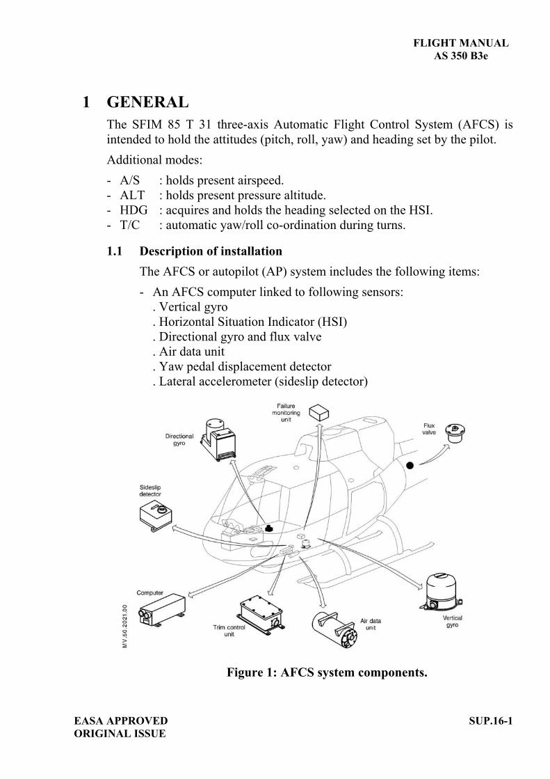
FLIGHT MANUAL
AS 350 B3e
1 GENERAL The SFIM 85 T 31 three-axis Automatic Flight Control System (AFCS) is intended to hold the attitudes (pitch, roll, yaw) and heading set by the pilot. Additional modes: - A/S : holds present airspeed. - ALT : holds present pressure altitude. - HDG : acquires and holds the heading selected on the HSI. - T/C : automatic yaw/roll co-ordination during turns.
1.1 Description of installation The AFCS or autopilot (AP) system includes the following items: - An AFCS computer linked to following sensors:
. Vertical gyro
. Horizontal Situation Indicator (HSI)
. Directional gyro and flux valve
. Air data unit
. Yaw pedal displacement detector
. Lateral accelerometer (sideslip detector)
Figure 1: AFCS system components.
EASA APPROVED SUP.16-1ORIGINAL ISSUE
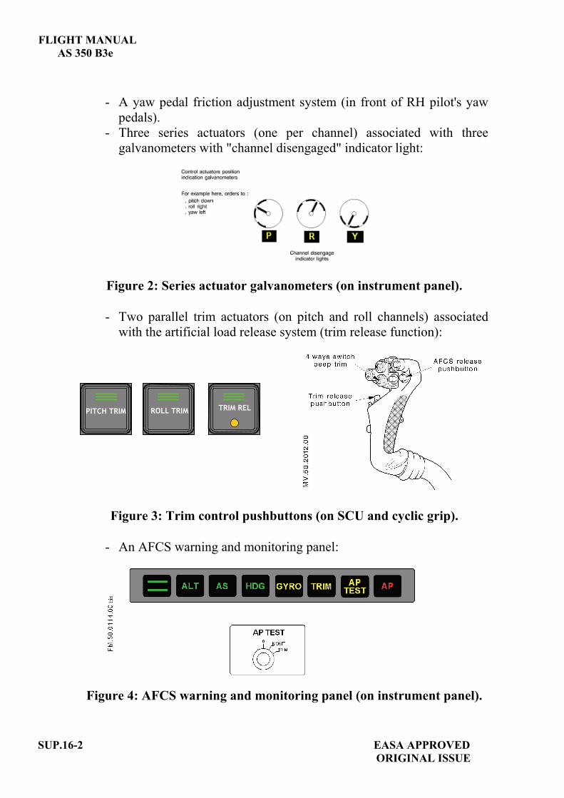
FLIGHT MANUAL AS 350 B3e
SUP.16-2 EASA APPROVED ORIGINAL ISSUE
- A yaw pedal friction adjustment system (in front of RH pilot's yaw pedals).
- Three series actuators (one per channel) associated with three galvanometers with "channel disengaged" indicator light:
Figure 2: Series actuator galvanometers (on instrument panel).
- Two parallel trim actuators (on pitch and roll channels) associated
with the artificial load release system (trim release function):
Figure 3: Trim control pushbuttons (on SCU and cyclic grip).
- An AFCS warning and monitoring panel:
Figure 4: AFCS warning and monitoring panel (on instrument panel).
TRIM REL PITCH TRIM ROLL TRIM
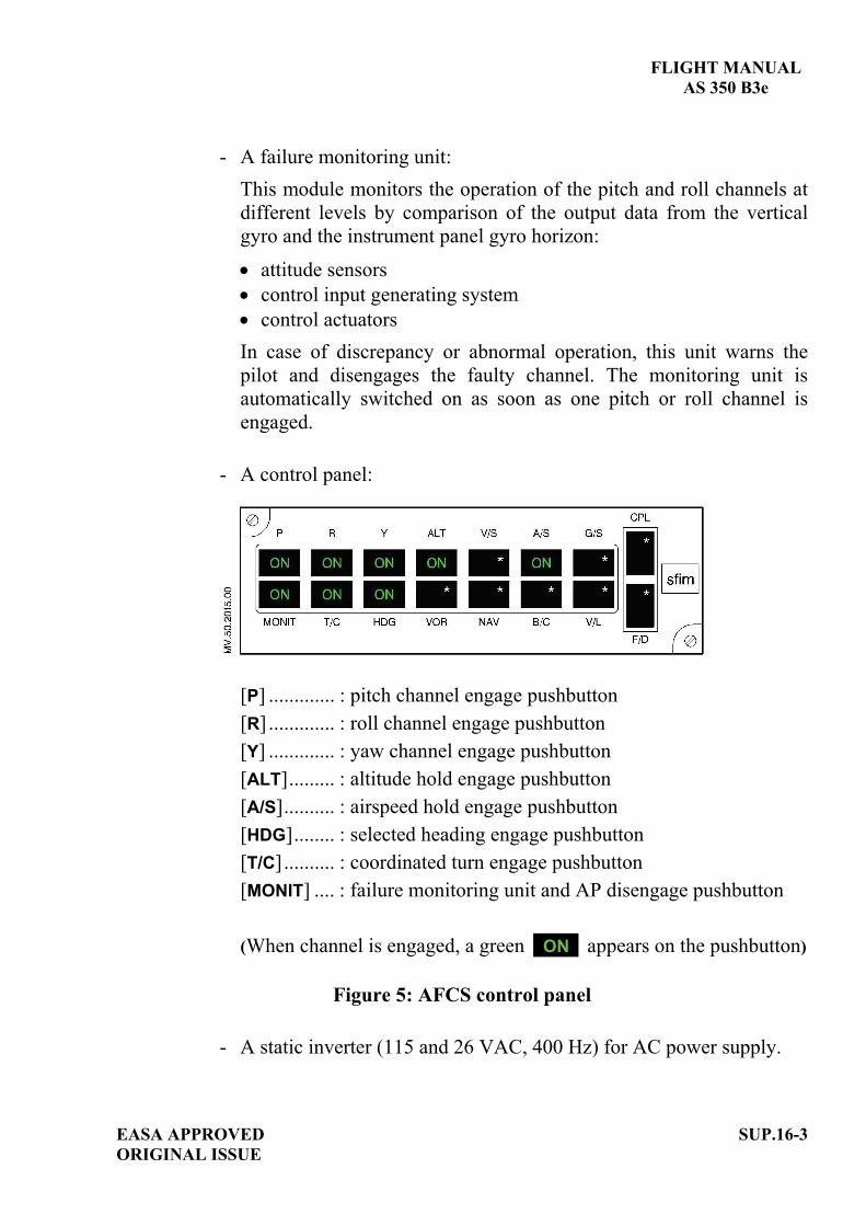
FLIGHT MANUAL AS 350 B3e
EASA APPROVED SUP.16-3 ORIGINAL ISSUE
- A failure monitoring unit: This module monitors the operation of the pitch and roll channels at different levels by comparison of the output data from the vertical gyro and the instrument panel gyro horizon:
attitude sensors control input generating system control actuators
In case of discrepancy or abnormal operation, this unit warns the pilot and disengages the faulty channel. The monitoring unit is automatically switched on as soon as one pitch or roll channel is engaged.
- A control panel:
[P] ............. : pitch channel engage pushbutton [R] ............. : roll channel engage pushbutton [Y] ............. : yaw channel engage pushbutton [ALT]......... : altitude hold engage pushbutton [A/S].......... : airspeed hold engage pushbutton [HDG]........ : selected heading engage pushbutton [T/C].......... : coordinated turn engage pushbutton [MONIT] .... : failure monitoring unit and AP disengage pushbutton (When channel is engaged, a green ON appears on the pushbutton)
Figure 5: AFCS control panel
- A static inverter (115 and 26 VAC, 400 Hz) for AC power supply.

FLIGHT MANUAL AS 350 B3e
2 LIMITATIONSThe limitations specified in the basic flight manual and in the flight manual supplements remain applicable and are completed or modified by the following:
2.1 AFCS ENGAGEMENT - When the aircraft is on ground, the AFCS must be disengaged except
if checks are to be performed. - Do not engage the AFCS before takeoff if trim test is not
satisfactory.
2.2 HEIGHT LIMITATION - Minimum height for AFCS hands-off operation: 400 ft (120 m).
3 EMERGENCY PROCEDURESThe emergency procedures specified in the basic flight manual and in the flight manual supplements remain applicable and are completed or modified by the following: 3.1 UNCOMMANDED AFCS INPUTS
If jerks or sudden movements independent of air turbulence are felt during the flight with the AFCS engaged: - AFCS ....................................... Disengage
Anomaly disappears:
YES NO
- AFCS .Re-engage channels one at a time.
Faulty channel identified AFCS not faulty
- AFCS .Disengage faulty channel Re-engage AFCS if required. re-engage other channels as required.
CONTINUE FLIGHT
SUP.16-4 EASA APPROVEDORIGINAL ISSUE

FLIGHT MANUAL
AS 350 B3e
3.2 HYDRAULIC SYSTEM FAILURE - Apply hydraulic failure procedure (refer to SECTION 3). - Disengage AFCS.
3.3 VERTICAL GYRO, GYRO HORIZON OR MONITORING UNIT FAILURE
WARNING CORRECTIVE ACTIONS
Flashing for 10 sec. +
or/andflag on gyro horizon.
+[ P ], [ R ], [ MONIT ] pushbutton lights go out
+lights on.
Monitoring unit failure.
Automatic disengagement of: . pitch channel,. roll channel, . monitoring unit.
Cyclic and collective controls.............HANDS ON.
- HDG, ALT and A/S modes are inoperative.
- Yaw channel remains operative.
CONTINUE FLIGHT RP
3.4 HARDOVERWARNING CORRECTIVE ACTIONS
Flashing for 10 sec. +
Automatic disengagementof faulty channel.
Hardover to the faulty channel.
Controls................................................HANDS ON.
NOTE Power reduction may be required to comply with the limitations.
CONTINUE FLIGHT
EASA APPROVED SUP.16-5ORIGINAL ISSUE

FLIGHT MANUAL AS 350 B3e
3.5. GYRO-COMPASS FAILURE:
WARNING CORRECTIVE ACTIONS
Flashing for 10 sec. +
HDG flag on HSI +
[ Y ] and [ T/C ] pushbutton lights go off
+light comes on
+[HDG] pushbutton +
lights go off (if HDG engaged).
Automatic disengagement of:. yaw channel,. selected HDG function.
Pedals ...............................FEET ON. - Yaw control by the pilot. - HDG mode and yaw channel are inoperative. - Pitch and roll channel remain operative.
CONTINUE FLIGHT Y
3.6. TRIM FAILURE:
WARNING CORRECTIVE ACTIONS
Comes on for 10 sec. +
Automatic disengagementof faulty trim.
Before auto disengagement, cyclic tends to move in direction of the failure.
Controls ..........................HANDS ON.Trim release (on cyclic)...Press momentarily while: Depending on trim failure:
-PRESS, to deactivate the faulty trim channel.
-
AFCS ...............................Re-engage. NOTE
The AFCS continues to operate without the faulty channel being trimmed.
Faulty channel galvanometer ....................Re-trim with cyclic trim
release button. CONTINUE FLIGHT
PITCH-TRIM
ROLL-TRIM
SUP.16-6 EASA APPROVED ORIGINAL ISSUE

FLIGHT MANUAL AS 350 B3e
EASA APPROVED SUP.16-7 ORIGINAL ISSUE
3.7. ARTIFICIAL LOAD SYSTEM SEIZURE:
WARNING CORRECTIVE ACTIONS
Cyclic stick seizure.
One parallel trim actuator
is seized.
Cyclic trim release.................... PRESS. Seizure disappears.
NO YES
................ PRESS. On corresponding cyclic channel…….Apply a load of 10 kg (22 lb) to break the trim mechanical shear device.
CONTINUE FLIGHT
3.8. ELECTRICAL POWER SUPPLY FAILURE: 3.8.1. AC power supply failure
WARNING CORRECTIVE ACTIONS
Flashing for 10 sec.
+
Automatic disengagement of AFCS. Controls..................................... HANDS ON.
................................... Check ON.
YES NO
AC power failure. ….... ... PRESS.
CONTINUE FLIGHT
3.8.2. Complete electrical power supply failure In the event of total power supply failure, AFCS disengages automatically and cannot be re-engaged.
INV
TRIM REL
INV
INV

FLIGHT MANUAL AS 350 B3e
4. NORMAL PROCEDURESThe normal procedures specified in the basic flight manual and in the flight manual supplements remain applicable and are completed or modified by the following:
4.1. RUN-UP CHECK: ADD:
1. …... Check in OFF position.
2. Cyclic friction .......................... Un-tightened. 3. Yaw pedal friction ................... Tightened.
4. ...................................... ON INV .
5. HSI ........................................... No HDG flag. 6. Gyro horizon(s)........................ No flag.
INV
4.1.1. AFCS test: 1. Test selector switch
set to "0" .......................All AFCS lights OFF. 2. [W/L TST] ...................PRESS, check:
Warning and monitoring panel lights ON.
AFCS control panel lights ON.3. Pitch, roll, yaw channels Engage:
[ P ], [ R ], [ Y ] and [MONIT]Check: ON .galvanometer lights OFF.
4. Cyclic beep trim ........ Check operation in the 4 directions and that relevant galvanometer pointer direction changes.
5. AFCS ......................... Switch OFF via pilot's cyclic. flashes for 10 sec., then .
6. Repeat (3.) to (5.) for copilot's cyclic (if installed).
SUP.16-8 EASA APPROVED ORIGINAL ISSUE

FLIGHT MANUAL AS 350 B3e
EASA APPROVED SUP.16-9 ORIGINAL ISSUE
4.1.2. Monitoring unit failure test: Pitch channel test:
1. Pitch channel ..............Engage: [ P ], [MONIT], check ON .
2. Cyclic beep trim ........Actuate in pitch: cyclic moves in relevant direction.
3. Test selector switch....Set to "MONIT": light on.
flashes for 10 sec., then
,
cyclic stops moving, galvanometers re-center, light
comes on. [MONIT] ON light flashes then
goes off. [ P ] pushbutton check ON .
4. Test selector switch....Set to "0", check . Roll channel test:
Same procedure as pitch channel. 4.1.3. Trim test:
CAUTION Do not operate the AFCS if trim light does not
come on or remains on during trim tests. Pitch channel test:
1. Pitch channel ..............Engage: [ P ], [MONIT] check ON .
2. Test selector switch....Set to "TRIM": light on.
lights up after 2 sec. delay
then, cyclic moves backward
alternately with light flashing. .
3. Test selector switch....Set to "0", check . 4. Pitch channel ..............Disengage:
[ P ] pushbutton, check ON .
(Fig. 4)
(Fig. 4)
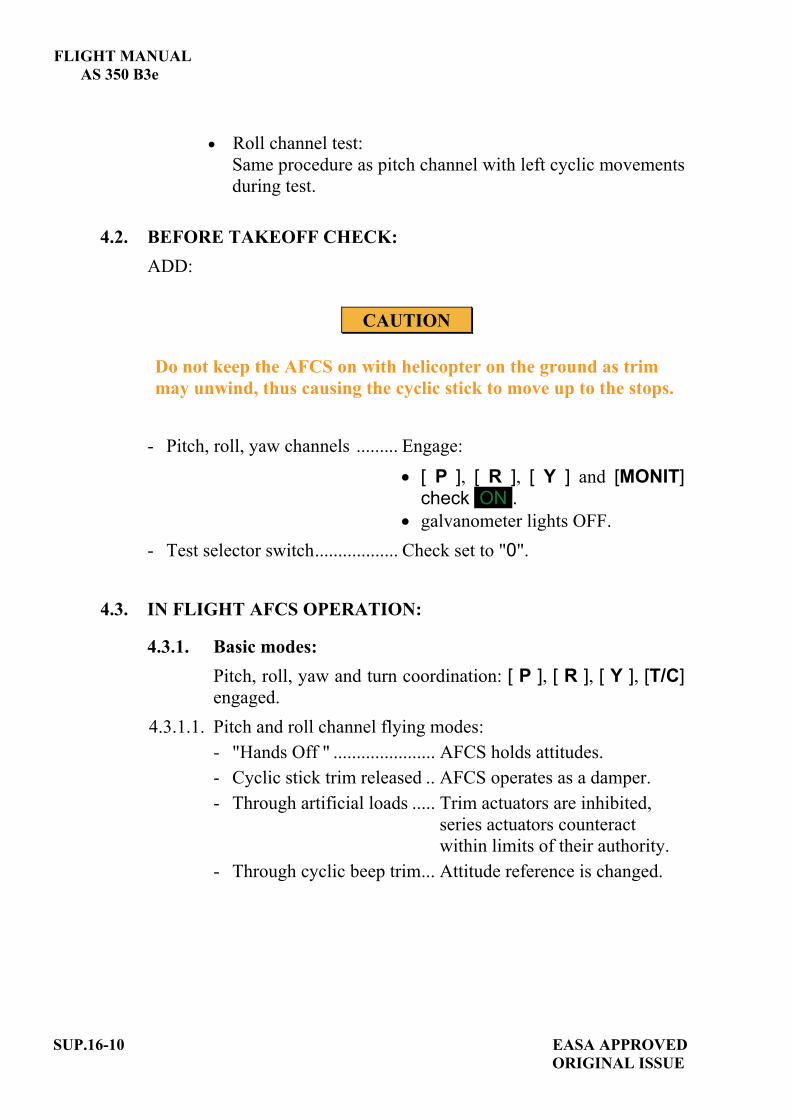
FLIGHT MANUAL AS 350 B3e
Roll channel test: Same procedure as pitch channel with left cyclic movements during test.
4.2. BEFORE TAKEOFF CHECK: ADD:
CAUTION
Do not keep the AFCS on with helicopter on the ground as trim may unwind, thus causing the cyclic stick to move up to the stops.
- Pitch, roll, yaw channels ......... Engage:
[ P ], [ R ], [ Y ] and [MONIT]check ON .galvanometer lights OFF.
- Test selector switch.................. Check set to "0".
4.3. IN FLIGHT AFCS OPERATION:
4.3.1. Basic modes: Pitch, roll, yaw and turn coordination: [ P ], [ R ], [ Y ], [T/C]engaged.
4.3.1.1. Pitch and roll channel flying modes: - "Hands Off " ...................... AFCS holds attitudes. - Cyclic stick trim released .. AFCS operates as a damper. - Through artificial loads ..... Trim actuators are inhibited, series actuators counteract within limits of their authority. - Through cyclic beep trim... Attitude reference is changed.
SUP.16-10 EASA APPROVED ORIGINAL ISSUE

FLIGHT MANUAL
AS 350 B3e
4.3.1.2 Yaw channel flying modes: - "Feet Off " ............................AFCS holds present heading
within its authority. - Operating yaw pedals ...........Heading reference is altered. - Heading change ....................Pilot must bring the helicopter
to the desired heading, whenrate of turn is < 1.5 °/sec.,present heading is captured. Then the pilot may fly "feet off" so that yaw channel can hold new heading.
4.3.1.3 Coordinated turns, T/C mode:
MODE OPERATING ENVELOPET/C
Yaw channel coordinates the turn.
- Airspeed greater than 50 KIAS (92 km/h – 57 MPH) - Angle of bank > 7°.
EASA APPROVED SUP.16-11ORIGINAL ISSUE

FLIGHT MANUAL AS 350 B3e
4.3.2 Additional modes
MODE OPERATING ENVELOPEHDG
HSI selected heading capture and hold via roll channel
- Airspeed greater than 50 KIAS (92 km/h - 57 MPH).
ALTAltitude hold via pitch channel
- Airspeed greater than 60 KIAS (111 km/h – 69 MPH).- Engagement with ROC < 1000 ft/min.
A/SAirspeed hold via pitch channel
- Airspeed greater than 50 KIAS (92 km/h - 57 MPH).
4.4 AFTER LANDING Disengage AFCS via the cyclic stick AFCS OFF pushbutton.
5 PERFORMANCEThe performance data specified in the basic flight manual and in the flight manual supplements remain applicable.
SUP.16-12 EASA APPROVEDORIGINAL ISSUE

EASA APPROVED SUP.17-TITLE ORIGINAL ISSUE
FLIGHT MANUAL
AS 350 B3e
SUPPLEMENT
EMERGENCY FLOATATION GEAR AERAZUR
IMPORTANT NOTE THE INFORMATION CONTAINED HEREIN SUPPLEMENTS OR SUPERSEDES THE INFORMATION GIVEN IN THE BASIC FLIGHT MANUAL AND/OR THE SUPPLEMENTS LISTED IN SECTION SUP.0. THE EFFECTIVITY OF THE SUPPLEMENT AT THE LATEST REVISION IS SPECIFIED ON THE LIST OF EFFECTIVE PAGES.
THIS SUPPLEMENT MUST BE INCLUDED IN THE FLIGHT MANUAL WHEN THE EQUIPMENT MENTIONED ABOVE IS INSTALLED ON THE AIRCRAFT.
E U R O C O P T E R D i r e c t i o n T e c h n i q u e S u p p o r t Aéroport international Marseille-Provence 13725 Marignane Cedex – France


FLIGHT MANUAL AS 350 B3e
EASA APPROVED AORIGINAL ISSUE
SUP.17-A
LIST OF APPROVED EFFECTIVE PAGES - EASA CERTIFICATION REMARKS / EFFECTIVITY column:
Without indication ......Applicable to all aircraft. Clear text definition ...Effectivity (specified model or variant type ...), information
... A : Specific to EASA.
...S/N nnnn: Specific to S/N nnnn.
PAGE REVNo.
REMARKS / EFFECTIVITY PAGE REV
No.REMARKS /
EFFECTIVITYSUP.17-Title 0
SUP.17-A 0 A
SUP.17-B 0 A
SUP.17-1 0
SUP.17-2 0
SUP.17-3 0
SUP.17-4 0
SUP.17-5 0

FLIGHT MANUAL
AS 350 B3e
SUP.17-B A
EASA APPROVEDORIGINAL ISSUE
LOG OF APPROVED NORMAL REVISIONS BASIC RFM REVISIONS - EFFECTIVITY EASA
NORMAL REVISION 0 - DECEMBER 2010 EASA approval No. 10035374 on June 17, 2011
Title New flight manual. Revised
information All pages.
Deleted information None

FLIGHT MANUAL
AS 350 B3e
1 GENERAL The emergency floatation gear is approved for emergency use (not for ditching according to JAR / FAR 27) i. e. to aid in keeping the rotorcraft sufficiently upright and in adequate trim to permit safe and orderly evacuation in case of emergency alighting on water. The emergency floatation gear consists of a landing gear assembly fitted with: - two floatation units mounted parallel along each skid of the aircraft (1). - a system for inflating the floats from 2 cylinders (one for each float) (2). The
cylinders are fitted with a pressure indicator. - an electrical control system with a FLOAT ARM pushbutton (4) on the SCU
to arm the system. - a FLOAT FIRE pushbutton under guard (3) on the collective grip.
1 2
34
FLOAT ARM
Figure 1: Emergency floatation gear
EASA APPROVED SUP.17-1ORIGINAL ISSUE

FLIGHT MANUAL AS 350 B3e
SUP.17-2 EASA APPROVED ORIGINAL ISSUE
2 LIMITATIONS The limitations specified in the basic flight manual and in the flight manual supplements remain applicable and are completed or modified by the following: - Minimum weight with OAT < 0°C: 1480 kg (3263 lb) to comply with the
minimum rotor rpm in case of engine failure. - Emergency floatation gear stowed - system armed or floats inflated:
maximum indicated airspeed, power on: 135 kt (250 km/h) maximum indicated airspeed, with Torque < 40 %: 100 kt (185 km/h)
- Maximum altitude for float inflation: 6600 ft (2000 m). - When flying at less than 400 ft (122 m) above water, the emergency
floatation gear must always be armed. - The limit values for the pressure in the inflation cylinder, provided by the
following tables, are applicable if the flight requires the emergency floatation gear to be armed.
NOTE The placard located adjacent to the cylinder provides the limit values.

FLIGHT MANUAL
AS 350 B3e
3. EMERGENCY PROCEDURES The emergency procedures specified in the basic flight manual and in the flight manual supplements remain applicable and are completed or modified by the following:
With FLOAT ARM set to arm:
CORRECTIVE ACTIONS
Floatation system failure
Float inflation not possible.
CONTINUE FLIGHTFlight path should remain within gliding distance
from the land.
Or
Float inflation remains possible for both floatation units:
CONTINUE FLIGHT
INFLATION PROCEDURE In the event of engine failure or other urgent requirement to alight on water, check the rotor speed then apply the following procedure:
FLOAT ARM .......................................................ON.
FLOAT ARM lights 1 and 2 ................................CHECK ON.
FLOAT FIRE under guard on collective grip .....PRESS (recommended firing IAS: below 80 kt - 148 km/h).
NOTE A deceleration with a pitch down movement can occur when inflating the floatation gear at a speed greater than 80 KIAS (148 km/h).
EASA APPROVED SUP.17-3ORIGINAL ISSUE

FLIGHT MANUAL AS 350 B3e
AUTORATION PROCEDURE OVER WATER WITH EMERGENCY FLOATATION GEAR
1. Collective pitch................................ REDUCE to maintain NR in green arc.
2. IAS.................................................... Vy.
If relighting impossible or after tail rotor failure. 3. Starting selector ................................ OFF position. 4. Maneuver to head the aircraft equally between the wind and wave
direction on final approach.
At height 70 ft (21 m)5. Cyclic................................................ Flare.
At 20-25 ft (6/8 m) at constant attitude6. Collective pitch................................. GRADUALLY INCREASE
to reduce the rate of descent andforward speed.
7. Cyclic................................................ FORWARD slightly to adopt attitude of 10° nose-up and a forward speed less than 10 kt (19 km/h) on touch-down.
8. Pedals................................................ ADJUST to cancel any side-slip tendency.
9. Collective pitch................................. INCREASE to cushion touch down with minimum speed.
After touch-down10. Collective pitch................................ Gradually decrease to fully down. 11. Rotor brake ...................................... APPLY.12. Evacuate aircraft once the rotor has stopped.
SUP.17-4 EASA APPROVED ORIGINAL ISSUE

FLIGHT MANUAL
AS 350 B3e
CAUTION
When the helicopter is afloat, the forward doors must be opened by actuating the door jettison handles.
4 NORMAL PROCEDURE The normal procedures specified in the basic flight manual and in the flight manual supplements remain applicable and are completed or modified by the following:- Exterior check:
Floatation units ................................................... LOCK in the lowered position.
Protective covers condition ................................ CHECK. Pressure in the two inflation cylinders ............... CHECK.
NOTEThe placard located adjacent to the cylinder provides the limit values.
- Interior check: Arming of the emergency floatation gear:
FLOAT ARM ..................................................... ON.
FLOAT ARM lights 1 and 2 .............................. CHECK ON.
Disarming the emergency floatation gear:
FLOAT ARM ..................................................... RESET in OFF position.
FLOAT ARM lights 1 and 2 .............................. CHECK OFF.
5 PERFORMANCE The performance data specified in the basic flight manual and in the flight manual supplements remain applicable and are completed or modified by the following:- The rate of climb must be reduced by 50 ft/min (0.25 m/s) (SECTION 5.1
Regulatory Performance) at Vy. - The cruising speed is reduced by approximately 2 kt (3.7 km/h) (SECTION
5.2 Complementary Performance).
EASA APPROVED SUP.17-5ORIGINAL ISSUE


EASA APPROVED SUP.18-TITLE ORIGINAL ISSUE
FLIGHT MANUAL
AS 350 B3e
SUPPLEMENT
"BREEZE" or "AIR EQUIPMENT" ELECTRIC HOIST
136 kg (300 lb)
IMPORTANT NOTE THE INFORMATION CONTAINED HEREIN SUPPLEMENTS OR SUPERSEDES THE INFORMATION GIVEN IN THE BASIC FLIGHT MANUAL AND/OR THE SUPPLEMENTS LISTED IN SECTION SUP.0. THE EFFECTIVITY OF THE SUPPLEMENT AT THE LATEST REVISION IS SPECIFIED ON THE LIST OF EFFECTIVE PAGES.
THIS SUPPLEMENT MUST BE INCLUDED IN THE FLIGHT MANUAL WHEN THE EQUIPMENT MENTIONED ABOVE IS INSTALLED ON THE AIRCRAFT.
E U R O C O P T E R D i r e c t i o n T e c h n i q u e S u p p o r t Aéroport international Marseille-Provence 13725 Marignane Cedex – France


FLIGHT MANUAL AS 350 B3e
EASA APPROVED AORIGINAL ISSUE
SUP.18-A
LIST OF APPROVED EFFECTIVE PAGES - EASA CERTIFICATION REMARKS / EFFECTIVITY column:
Without indication ......Applicable to all aircraft. Clear text definition ...Effectivity (specified model or variant type ...), information
... A : Specific to EASA.
...S/N nnnn: Specific to S/N nnnn.
PAGE REVNo.
REMARKS / EFFECTIVITY PAGE REV
No.REMARKS /
EFFECTIVITYSUP.18-Title 0
SUP.18-A 0 A
SUP.18-B 0 A
SUP.18-1 0
SUP.18-2 0
SUP.18-3 0
SUP.18-4 0
SUP.18-5 0
SUP.18-6 0
SUP.18-7 0
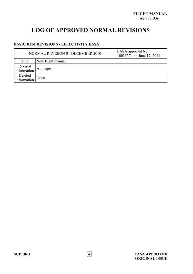
FLIGHT MANUAL
AS 350 B3e
SUP.18-B A
EASA APPROVEDORIGINAL ISSUE
LOG OF APPROVED NORMAL REVISIONS BASIC RFM REVISIONS - EFFECTIVITY EASA
NORMAL REVISION 0 - DECEMBER 2010 EASA approval No. 10035374 on June 17, 2011
Title New flight manual. Revised
information All pages.
Deleted information None
FLIGHT MANUAL
AS 350 B3e
1 GENERALThe hoist installation is designed to raise or lower on board loads while the aircraft is hovering. The helicopter can be fitted with either of the following two electric hoists:
"Breeze" BL 16600
"Air Equipment" 76370 1.1 DESCRIPTION OF THE INSTALLATION
The hoist installation comprises: - a pivoting jib (2) equipped with a locking device (3) (ferrying and
hoisting position), mounted on the port side of the helicopter, - a hoist (1) driven by a constant speed electric motor and fitted with:
a 33.5 m (110 ft) cable for the Breeze hoist, a 40 m (130 ft) cable for the Air Equipment hoist.
- a snap hook mounted on a pulley-block tackle (if available) (6), - an electrical power supply circuit, - two cable protectors (8) secured to the LH landing gear skid, - a hand cable cutter stowed on the rear wall allows the hoist operator
to sever the cable, if necessary, - an "Up travel limit" detector which switches off the electrical power
supply when the hook is fully up, - a "Down travel limit" detector which cuts off the electrical power
supply when 4 m of cable are left on the drum, - a mechanical safety pin stopping the hoist drum when 3 m of cable
are left in case of electrical "Down travel limit" failure. The electrical system is protected by:- one 100 A fuse located in the Electrical Master Box, - one 60 A breaker located on the aft wall (4) near the hoist operator's
grip support, these two first fuse or circuit breaker supply the hoist, - two 2.5 A breakers protecting the “emergency cable cutter” circuit, - one 2.5 A breaker protecting the "up-down" circuit.
NOTE The hoist is fitted with a pyrotechnic cable cutter.
EASA APPROVED SUP.18-1ORIGINAL ISSUE

FLIGHT MANUAL AS 350 B3e
SUP.18-2 EASA APPROVED ORIGINAL ISSUE
1.2 CONTROLS AND INDICATORS AVAILABLE TO THE CREW
Figure 1: Hoist controls
Controls available to the pilot: - a [HOIST] pushbutton (9) located on the SCU is used for
switching on the installation. - a cable shear guarded pushbutton located on the collective
pitch lever which is used to sever the hoist cable in case of an emergency.
FLIGHT MANUAL
AS 350 B3e
Controls and indicators available to the hoist operator: - a rocker switch (7) on the hoist operator's control grip used to
raise, lower or stop the cable. - one green light on the hoist for "Hoist moving UP" - one red light on the hoist for "UP limit" microswitch test.
2 LIMITATIONS The limitations specified in the basic flight manual and in the flight manual supplements remain applicable and are completed or modified by the following:
2.1 MINIMUM CREWOne pilot and one hoist operator.
2.2 WEIGHT LIMITATION Maximum permissible load on hoist cable: 136 kg (300 lb).
2.3 OPERATING LIMITATIONSAir Equipment hoist: - to avoid overheating of hoist motor, never exceed 6 consecutive
hoisting operations plus one descent with maximum load, and maximum cable reel-out or equivalent.
Breeze hoist: - after each operation (lowering or raising), wait 30 sec.
NOTE After 3 complete cycles (one descent at max. load, the two followingdescents with no load, combined with three raising operations at max. load) it is recommended to stop the hoist for 40 min.
2.4 HAND CABLE CUTTERA hand operated cable cutter must be readily available to the hoist operator.
2.5 LANDINGLanding with a load suspended on the hoist cable is forbidden.
EASA APPROVED SUP.18-3ORIGINAL ISSUE

FLIGHT MANUAL AS 350 B3e
3 EMERGENCY PROCEDURESThe emergency procedures specified in the basic flight manual and in the flight manual supplements remain applicable and are completed or modified by the following: 3.1 HOIST FAILURE
According to the load carried and the circumstances, the crew can either:- manually pull the cable inside the aircraft if possible or, - cut the cable or, - return to base while slightly inclining the hoist cable, with a VNE of
60 KIAS (111 km/h).
3.2 ENGINE FAILURE - IN HOVER:
1. Collective pitch.............................REDUCE according to the height.
2. Load ..............................................RELEASE as soon as possible (Emergency cable-shearing pushbutton on collective grip)
3. Pedals ............................................Control yaw. 4. Cyclic ............................................Forward to gain forward
speed according to the height 5. Collective pitch.............................INCREASE as necessary to
cushion touch-down
NOTE In case of an engine failure during a hoisting phase, the pilot should move away to the right. Ground crew if any must beforewarned that in the event of engine failure they must escape to the left of the helicopter.
3.3 ICS FAILURE According to the circumstances: - Complete present hoisting operation, - Abort hoisting mission.
SUP.18-4 EASA APPROVEDORIGINAL ISSUE
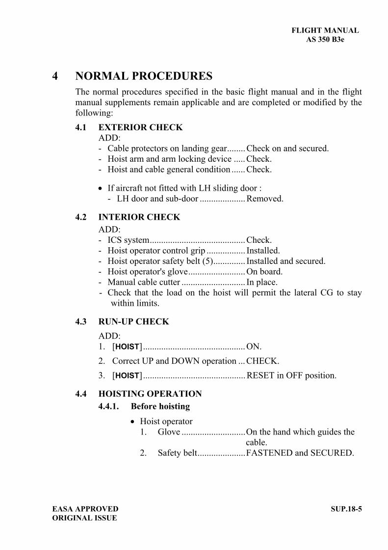
FLIGHT MANUAL
AS 350 B3e
4 NORMAL PROCEDURESThe normal procedures specified in the basic flight manual and in the flight manual supplements remain applicable and are completed or modified by the following:4.1 EXTERIOR CHECK
ADD:- Cable protectors on landing gear........ Check on and secured. - Hoist arm and arm locking device ..... Check. - Hoist and cable general condition ...... Check.
If aircraft not fitted with LH sliding door : - LH door and sub-door .................... Removed.
4.2 INTERIOR CHECK ADD:- ICS system.......................................... Check.- Hoist operator control grip ................. Installed.- Hoist operator safety belt (5).............. Installed and secured. - Hoist operator's glove......................... On board. - Manual cable cutter ............................ In place. - Check that the load on the hoist will permit the lateral CG to stay
within limits.
4.3 RUN-UP CHECK ADD:1. [HOIST]............................................. ON. 2. Correct UP and DOWN operation ... CHECK. 3. [HOIST]............................................. RESET in OFF position.
4.4 HOISTING OPERATION 4.4.1. Before hoisting
Hoist operator 1. Glove ............................On the hand which guides the cable. 2. Safety belt.....................FASTENED and SECURED.
EASA APPROVED SUP.18-5ORIGINAL ISSUE

FLIGHT MANUAL AS 350 B3e
Pilot1. Pilot/Hoist operator ICS......CHECK operative. 2. Door opening ......................ORDER when IAS 60 kt (111 km/h).3. Heating and demisting........OFF.4. Power margin available ......CHECK.5. All parameters ....................CHECK.
4.4.2 Hoisting
WARNING
TO DISCHARGE POSSIBLE STATIC ELECTRICITY FROM THE AIRCRAFT, THE HOOK SHALL HAVE GROUND CONTACT BEFORE THE CABLE IS GRASPED.
IF THE HOOK COMES INTO CONTACT FORCEFULLY WITH THE UPPER MECHANICAL STOP (FAILURE OF THE HOISTING AUTOMATIC STOP SYSTEM), ABORT THE HOISTING MISSION.
CAUTION
Take all precautions to prevent the load being hoisted from hitting any part of the helicopter.
When helicopter stabilized above the hoisting site: 1. Hoist jib ..............................SET in hoisting position. 2. [HOIST] ...............................ON. Hoist operator controls the hoist. To bring the load into the cabin, unlock the jib and pivot it inwards. The snap-hook (if available) can be used to hold the load while the load is unhooked.If the option is installed, the hoist may be operated by the pilot using the rocker switch on the cyclic grip.
SUP.18-6 EASA APPROVEDORIGINAL ISSUE

FLIGHT MANUAL
AS 350 B3e
4.4.3 After hoisting operation 1. Hoist jib..........................SET in ferrying position. 2. [HOIST]...........................RESET in OFF position. 3. Door closing...................As required (check VNE with
door open SECTION 2).
5 PERFORMANCEThe performance data specified in the basic flight manual and in the flight manual supplements remain applicable.
EASA APPROVED SUP.18-7ORIGINAL ISSUE


EASA APPROVED SUP.19-TITLE ORIGINAL ISSUE
FLIGHT MANUAL
AS 350 B3e
SUPPLEMENT
"BREEZE" ELECTRIC HOIST 204 kg (450 lb)
IMPORTANT NOTE THE INFORMATION CONTAINED HEREIN SUPPLEMENTS OR SUPERSEDES THE INFORMATION GIVEN IN THE BASIC FLIGHT MANUAL AND/OR THE SUPPLEMENTS LISTED IN SECTION SUP.0. THE EFFECTIVITY OF THE SUPPLEMENT AT THE LATEST REVISION IS SPECIFIED ON THE LIST OF EFFECTIVE PAGES.
THIS SUPPLEMENT MUST BE INCLUDED IN THE FLIGHT MANUAL WHEN THE EQUIPMENT MENTIONED ABOVE IS INSTALLED ON THE AIRCRAFT.
E U R O C O P T E R D i r e c t i o n T e c h n i q u e S u p p o r t Aéroport international Marseille-Provence 13725 Marignane Cedex – France

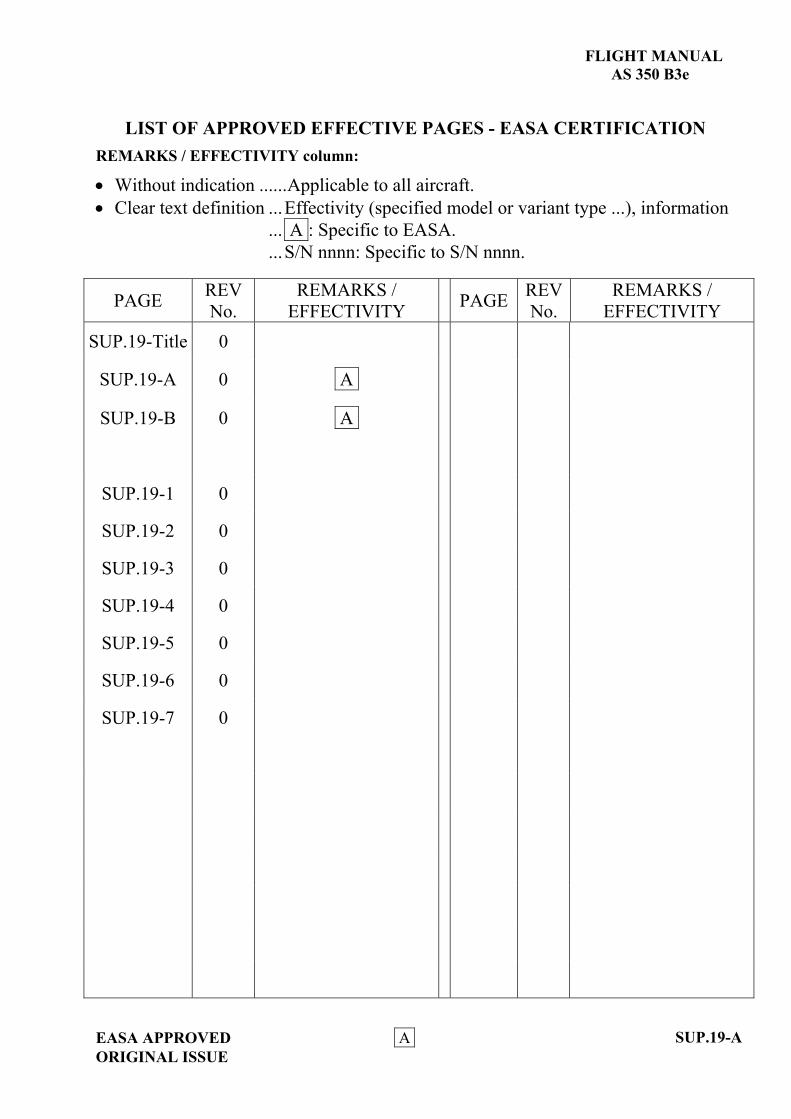
FLIGHT MANUAL AS 350 B3e
EASA APPROVED AORIGINAL ISSUE
SUP.19-A
LIST OF APPROVED EFFECTIVE PAGES - EASA CERTIFICATION REMARKS / EFFECTIVITY column:
Without indication ......Applicable to all aircraft. Clear text definition ...Effectivity (specified model or variant type ...), information
... A : Specific to EASA.
...S/N nnnn: Specific to S/N nnnn.
PAGE REVNo.
REMARKS / EFFECTIVITY PAGE REV
No.REMARKS /
EFFECTIVITYSUP.19-Title 0
SUP.19-A 0 A
SUP.19-B 0 A
SUP.19-1 0
SUP.19-2 0
SUP.19-3 0
SUP.19-4 0
SUP.19-5 0
SUP.19-6 0
SUP.19-7 0

FLIGHT MANUAL
AS 350 B3e
SUP.19-B A
EASA APPROVEDORIGINAL ISSUE
LOG OF APPROVED NORMAL REVISIONS BASIC RFM REVISIONS - EFFECTIVITY EASA
NORMAL REVISION 0 - DECEMBER 2010 EASA approval No. 10035374 on June 17, 2011
Title New flight manual. Revised
information All pages.
Deleted information None

FLIGHT MANUAL
AS 350 B3e
1 GENERALThe hoist installation is designed to raise or lower on board loads while the aircraft is hovering. 1.1 DESCRIPTION OF THE INSTALLATION
The hoist installation comprises: - a pivoting jib (2) equipped with a locking device (3) (ferrying and
hoisting position), mounted on the port side of the helicopter. - a hoist (1) driven by a variable speed electric motor and fitted with a
50 m cable. - a snap hook mounted on a pulley-block tackle (if available) (7), - an electrical power supply and control circuit, - two cable protectors (8) secured to the LH landing gear skid, - a hand cable cutter stowed on the rear wall allows the hoist operator
to sever the hoist cable, if necessary, - an electronic control unit secured inside the LH side cargo hold,
providing: control of the hoist up/down speed automatic deceleration before reaching the high and low travel limits automatic stopping at the travel limit and in the event of incorrect winding of the cable.
The system is protected by:- one 130 A fuse located in the Electrical Master Box, - two 7.5 A breakers protecting the “emergency cable cutter” circuit
located on the aft wall (4), - one 100 A breaker on the hoist power supply system for cut off and
rearming located on the aft wall (4), - one 2.5 A breaker and one 6.3 A breaker for the control circuit
located on the center console.
NOTE The hoist is fitted with a pyrotechnic cable cutter.
EASA APPROVED SUP.19-1ORIGINAL ISSUE

FLIGHT MANUAL AS 350 B3e
SUP.19-2 EASA APPROVED ORIGINAL ISSUE
1.2 CONTROLS AND INDICATORS AVAILABLE TO THE CREW
Figure 1: Hoist controls

FLIGHT MANUAL
AS 350 B3e
Controls available to the pilot : - a [HOIST] pushbutton (12) located on the SCU is used for
switching on the installation - a cable shear guarded pushbutton located on the collective pitch
lever which is used to sever the hoist cable in case of anemergency.
Controls and indicators available to the hoist operator on the hoist operator's control grip (5): - an intercom push-to-talk switch (9), - a thumbwheel (11) to control raising, lowering and stopping of the
cable. The cable winding speed is proportional to the displacement of the thumbwheel (11).
- an indicator (10) shows the length of cable unwound in meters.
2 LIMITATIONSThe limitations specified in the basic flight manual and in the flight manual supplements remain applicable and are completed or modified by the following:2.1 MINIMUM CREW
One pilot and one hoist operator.
2.2 WEIGHT LIMITATION Maximum permissible load on hoist cable............... : 204 kg (450 lb)
2.3 HAND CABLE CUTTERA hand operated cable cutter must be within reach of the hoist operator.
2.4 LANDINGLanding with a load suspended on the hoist cable is forbidden.
EASA APPROVED SUP.19-3ORIGINAL ISSUE

FLIGHT MANUAL AS 350 B3e
SUP.19-4 EASA APPROVED ORIGINAL ISSUE
3 EMERGENCY PROCEDURES The emergency procedures specified in the basic flight manual and in the flight manual supplements remain applicable and are completed or modified by the following: 3.1 HOIST FAILURE
According to the load carried and the circumstances, the crew can either: - manually pull the cable inside the aircraft if possible or, - cut the cable or, - return to base while slightly inclining the hoist cable, with a VNE of
60 KIAS (111 km/h).
3.2 ENGINE FAILURE - IN HOVER
1. Collective pitch. ............................REDUCE according to the height.
2. Load ..............................................RELEASE as soon as possible (Emergency cable-shearing pushbutton on collective grip)
3. Pedals ............................................Control yaw. 4. Cyclic ............................................Forward to gain forward
speed according to the height 5. Collective pitch.............................INCREASE as necessary to
cushion touch-down
NOTE In case of an engine failure during a hoisting phase, the pilot should move away to the right. Ground crew if any must be forewarned that in the event of engine failure they must escape to the left of the helicopter.
3.3 ICS FAILURE According to the circumstances: - Complete present hoisting operation, - Abort hoisting mission.

FLIGHT MANUAL
AS 350 B3e
4 NORMAL PROCEDURESThe normal procedures specified in the basic flight manual and in the flight manual supplements remain applicable and are completed or modified by the following:4.1 EXTERIOR CHECK
ADD:- Cable protectors on landing gear........ Check on and secured. - Hoist arm and arm locking device ..... Check. - Hoist and cable general condition ...... Check.
If aircraft not fitted with LH sliding door: - LH door and sub-door .................... Removed.
4.2 INTERIOR CHECK ADD:- ICS system.......................................... Check.- Hoist operator control grip ................. Installed.- Hoist operator safety belt (5).............. Installed and secured. - Hoist operator's glove......................... On board. - Manual cable cutter ............................ In place. - Check that the load on the hoist will permit the lateral CG to stay
within limits.
4.3 RUN-UP CHECK ADD:1. [HOIST] ............................................... ON. 2. Correct UP and DOWN operation ..... CHECK. 3. [HOIST] ............................................... RESET in OFF position.
4.4 HOISTING OPERATION 4.4.1 Before hoisting
Hoist operator 1. Glove ............................On the hand which guides the
cable.2. Safety belt.....................FASTENED and SECURED.
EASA APPROVED SUP.19-5ORIGINAL ISSUE

FLIGHT MANUAL AS 350 B3e
Pilot1. Pilot/Hoist operator ICS......CHECK operative. 2. Door opening ......................ORDER when IAS 60 kt (111 km/h).3. Heating and demisting........OFF.4. Power margin available ......CHECK.5. All parameters ....................CHECK.
4.4.2 Hoisting
WARNING
TO DISCHARGE POSSIBLE STATIC ELECTRICITY FROM THE AIRCRAFT, THE HOOK SHALL HAVE GROUND CONTACT BEFORE THE CABLE IS GRASPED.
IF THE HOOK COMES INTO CONTACT WITH FORCEFULLY THE UPPER MECHANICAL STOP (FAILURE OF THE HOISTING AUTOMATIC STOP SYSTEM), ABORT THE HOISTING MISSION.
CAUTION
Take all precautions to prevent the load being hoisted from hitting any part of the helicopter.
When helicopter stabilized above the hoisting site: 1. Hoist jib ................. SET in hoisting position. 2. [HOIST].................. ON.
Hoist operator controls the hoist. To bring the load into the cabin, unlock the jib and pivot it inwards. The snap-hook (if available) can be used to hold the load while the load is unhooked.If the option is installed, the hoist may be operated by the pilot using the rocker switch on the cyclic grip.
SUP.19-6 EASA APPROVEDORIGINAL ISSUE

FLIGHT MANUAL
AS 350 B3e
4.4.3 After hoisting operation 1. Hoist jib..........................SET in ferrying position. 2. [HOIST]...........................RESET in OFF position. 3. Door closing...................As required (check VNE with
door open SECTION 2).
5 PERFORMANCEThe performance data specified in the basic flight manual and in the flight manual supplements remain applicable.
EASA APPROVED SUP.19-7ORIGINAL ISSUE


EASA APPROVED SUP.19.1-TITLE ORIGINAL ISSUE
FLIGHT MANUAL
AS 350 B3e
SUPPLEMENT
"BREEZE" ELECTRIC HOIST 204 kg (450 lb)
Grip with support bracket
IMPORTANT NOTE THE INFORMATION CONTAINED HEREIN SUPPLEMENTS OR SUPERSEDES THE INFORMATION GIVEN IN THE BASIC FLIGHT MANUAL AND/OR THE SUPPLEMENTS LISTED IN SECTION SUP.0. THE EFFECTIVITY OF THE SUPPLEMENT AT THE LATEST REVISION IS SPECIFIED ON THE LIST OF EFFECTIVE PAGES.
THIS SUPPLEMENT MUST BE INCLUDED IN THE FLIGHT MANUAL WHEN THE EQUIPMENT MENTIONED ABOVE IS INSTALLED ON THE AIRCRAFT.
E U R O C O P T E R D i r e c t i o n T e c h n i q u e S u p p o r t Aéroport international Marseille-Provence 13725 Marignane Cedex – France


FLIGHT MANUAL
AS 350 B3e
EASA APPROVED A ORIGINAL ISSUE
SUP.19.1-A
LIST OF APPROVED EFFECTIVE PAGES - EASA CERTIFICATION REMARKS / EFFECTIVITY column:
Without indication ......Applicable to all aircraft. Clear text definition ...Effectivity (specified model or variant type ...), information
... A : Specific to EASA.
...S/N nnnn: Specific to S/N nnnn.
PAGE REV No.
REMARKS / EFFECTIVITY PAGE REV
No. REMARKS /
EFFECTIVITY SUP.19.1-Title 0
SUP.19.1-A 0 A
SUP.19.1-B 0 A
SUP.19.1-1 0
SUP.19.1-2 0
SUP.19.1-3 0
SUP.19.1-4 0
SUP.19.1-5 0
SUP.19.1-6 0
SUP.19.1-7 0

FLIGHT MANUAL
AS 350 B3e
SUP.19.1-B A
EASA APPROVEDORIGINAL ISSUE
LOG OF APPROVED NORMAL REVISIONS BASIC RFM REVISIONS - EFFECTIVITY EASA
NORMAL REVISION 0 - DECEMBER 2010 EASA approval No. 10035374 on June 17, 2011
Title New flight manual. Revised
information All pages.
Deleted information None

FLIGHT MANUAL AS 350 B3e
EASA APPROVED SUP.19.1-1 ORIGINAL ISSUE
1 GENERAL The hoist installation is designed to raise or lower on board loads while the aircraft is hovering.
1.1 DESCRIPTION OF THE INSTALLATION The hoist installation comprises: - a pivoting jib (2) equipped with a locking device (3) (ferrying and
hoisting position), mounted on the port side of the helicopter. - a hoist (1) driven by a variable speed electric motor and fitted with a
50 m cable. - a snap hook mounted on a pulley-block tackle (if available) (7), - an electrical power supply and control circuit, - two cable protectors (8) secured to the LH landing gear skid, - a hand cable cutter stowed on the rear wall allows the hoist operator
to sever the hoist cable, if necessary, - an electronic control unit secured inside the LH side cargo hold,
providing: control of the hoist up/down speed automatic deceleration before reaching the high and low travel
limits automatic stopping at the travel limits and in the event of incorrect
winding of the cable. The system is protected by: - one 130 A fuse located in the Electrical Master Box, - two 7.5 A breakers protecting the “emergency cable cutter” circuit
located on the aft wall (4), - one 100 A breaker on the hoist power supply system for cut-off and
rearming circuit located on the aft wall (4), - one 2.5 A breaker and one 6.3 A breaker for the control circuit
located on the center console.
NOTE The hoist is fitted with a pyrotechnic cable cutter.
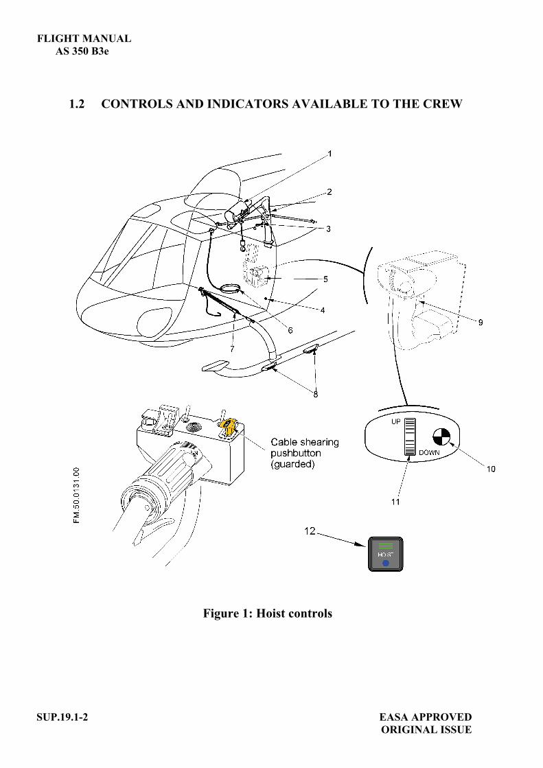
FLIGHT MANUAL AS 350 B3e
SUP.19.1-2 EASA APPROVED ORIGINAL ISSUE
1.2 CONTROLS AND INDICATORS AVAILABLE TO THE CREW
Figure 1: Hoist controls

FLIGHT MANUAL AS 350 B3e
EASA APPROVED SUP.19.1-3 ORIGINAL ISSUE
Controls available to the pilot: - a [HOIST] pushbutton (12) located on the SCU is used for
switching on the installation - a cable shear guarded pushbutton located on the collective pitch
lever which is used to sever the hoist cable in case of an emergency.
Controls and indicators available to the hoist operator on the hoist operator's control grip (5 ): - an intercom push-to-talk switch (9), - a thumbwheel (11) to control raising, lowering and stopping of the
cable. The cable winding speed is proportional to the displacement of the thumbwheel (11).
- a white indicator light (10) shows that the hoist installation is energized.
2 LIMITATIONS The limitations specified in the basic flight manual and in the flight manual supplements remain applicable and are completed or modified by the following:
2.1 MINIMUM CREW One pilot and one hoist operator.
2.2 WEIGHT LIMITATION Maximum permissible load on hoist cable : 204 kg (450 lb)
2.3 HAND CABLE CUTTER A hand operated cable cutter must be within reach of the hoist operator.
2.4 LANDING Landing with a load suspended on the hoist cable is forbidden.

FLIGHT MANUAL AS 350 B3e
SUP.19.1-4 EASA APPROVED ORIGINAL ISSUE
3 EMERGENCY PROCEDURES The emergency procedures specified in the basic flight manual and in the flight manual supplements remain applicable and are completed or modified by the following:
3.1 HOIST FAILURE According to the load carried and the circumstances, the crew can either: - manually pull the cable inside the aircraft if possible or, - cut the cable or, - return to base while slightly inclining the hoist cable, with a VNE of
60 KIAS (111 km/h).
3.2 ENGINE FAILURE - IN HOVER 1. Collective pitch. ................................REDUCE according to the
height. 2. Load ..................................................RELEASE as soon as possible
(Emergency cable-shearing pushbutton on collective grip)
3. Pedals ................................................Control yaw. 4. Cyclic ................................................Forward to gain forward speed
according to the height 5. Collective pitch .................................INCREASE as necessary to
cushion touch-down
NOTE In case of an engine failure during a hoisting phase, the pilot should move away to the right. Ground crew if any must be forewarned that in the event of engine failure they must escape to the left of the helicopter.
3.3 ICS FAILURE According to the circumstances: - Complete present hoisting operation, - Abort hoisting mission.
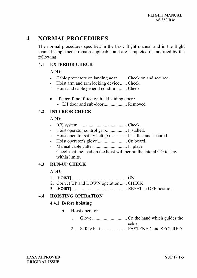
FLIGHT MANUAL AS 350 B3e
EASA APPROVED SUP.19.1-5 ORIGINAL ISSUE
4 NORMAL PROCEDURES The normal procedures specified in the basic flight manual and in the flight manual supplements remain applicable and are completed or modified by the following: 4.1 EXTERIOR CHECK
ADD: - Cable protectors on landing gear ........ Check on and secured. - Hoist arm and arm locking device ...... Check. - Hoist and cable general condition....... Check.
If aircraft not fitted with LH sliding door :
- LH door and sub-door.................... Removed. 4.2 INTERIOR CHECK
ADD: - ICS system .......................................... Check. - Hoist operator control grip.................. Installed. - Hoist operator safety belt (5) .............. Installed and secured. - Hoist operator's glove ......................... On board. - Manual cable cutter............................. In place. - Check that the load on the hoist will permit the lateral CG to stay
within limits. 4.3 RUN-UP CHECK
ADD: 1. [HOIST] ................................................ ON. 2. Correct UP and DOWN operation ...... CHECK. 3. [HOIST] ................................................ RESET in OFF position.
4.4 HOISTING OPERATION 4.4.1 Before hoisting
Hoist operator 1. Glove .............................. On the hand which guides the
cable. 2. Safety belt....................... FASTENED and SECURED.
FLIGHT MANUAL AS 350 B3e
SUP.19.1-6 EASA APPROVED ORIGINAL ISSUE
Pilot 1. Pilot/Hoist operator ICS......CHECK operative. 2. Door opening ......................ORDER when IAS 60 kt (111 km/h). 3. Heating and demisting........OFF. 4. Power margin available ......CHECK. 5. All parameters ....................CHECK.
4.4.2 Hoisting
WARNING
TO DISCHARGE POSSIBLE STATIC ELECTRICITY FROM THE AIRCRAFT, THE HOOK SHALL HAVE GROUND CONTACT BEFORE THE CABLE IS GRASPED.
IF THE HOOK COMES INTO CONTACT FORCEFULLY WITH THE UPPER MECHANICAL STOP (FAILURE OF THE HOISTING AUTOMATIC STOP SYSTEM), ABORT THE HOISTING MISSION.
CAUTION
Take all precautions to prevent the load being hoisted from hitting any part of the helicopter.
When helicopter stabilized above the hoisting site:
1. Hoist jib ..................... SET in hoisting position. 2. [HOIST] ...................... ON. Hoist operator controls the hoist. To bring the load into the cabin, unlock the jib and pivot it inwards. The snap-hook (if available) can be used to hold the load while the load is unhooked. If the option is installed, the hoist may be operated by the pilot using the rocker switch on the cyclic grip.

FLIGHT MANUAL AS 350 B3e
EASA APPROVED SUP.19.1-7 ORIGINAL ISSUE
4.4.3 After hoisting operation 1. Hoist jib......................SET in ferrying position. 2. [HOIST] ......................RESET in OFF position. 3. Door closing...............As required (check VNE with
door open SECTION 2).
5 PERFORMANCE The performance data specified in the basic flight manual and in the flight manual supplements remain applicable.

EASA APPROVED SUP.20-TITLE ORIGINAL ISSUE
FLIGHT MANUAL
AS 350 B3e
SUPPLEMENT
HYDRAULIC PUMP DRIVE ON MGB
IMPORTANT NOTE THE INFORMATION CONTAINED HEREIN SUPPLEMENTS OR SUPERSEDES THE INFORMATION GIVEN IN THE BASIC FLIGHT MANUAL AND/OR THE SUPPLEMENTS LISTED IN SECTION SUP.0. THE EFFECTIVITY OF THE SUPPLEMENT AT THE LATEST REVISION IS SPECIFIED ON THE LIST OF EFFECTIVE PAGES.
THIS SUPPLEMENT MUST BE INCLUDED IN THE FLIGHT MANUAL WHEN THE EQUIPMENT MENTIONED ABOVE IS INSTALLED ON THE AIRCRAFT.
E U R O C O P T E R D i r e c t i o n T e c h n i q u e S u p p o r t Aéroport international Marseille-Provence 13725 Marignane Cedex – France


FLIGHT MANUAL
AS 350 B3e
EASA APPROVED A ORIGINAL ISSUE
SUP.20-A
LIST OF APPROVED EFFECTIVE PAGES - EASA CERTIFICATION REMARKS / EFFECTIVITY column:
Without indication ......Applicable to all aircraft. Clear text definition ...Effectivity (specified model or variant type ...), information
... A : Specific to EASA.
...S/N nnnn: Specific to S/N nnnn.
PAGE REV No.
REMARKS / EFFECTIVITY PAGE REV
No. REMARKS /
EFFECTIVITY SUP.20-Title 0
SUP.20-A 0 A
SUP.20-B 0 A
SUP.20-1 0

FLIGHT MANUAL
AS 350 B3e
SUP.20-B A
EASA APPROVEDORIGINAL ISSUE
LOG OF APPROVED NORMAL REVISIONS BASIC RFM REVISIONS - EFFECTIVITY EASA
NORMAL REVISION 0 - DECEMBER 2010 EASA approval No. 10035374 on June 17, 2011
Title New flight manual. Revised
information All pages.
Deleted information None

FLIGHT MANUAL AS 350 B3e
EASA APPROVED SUP.20-1 ORIGINAL ISSUE
1 GENERAL An optional mechanical power output on the MGB enables the installation of a supplementary hydraulic pump for specific use. This output is driven by the MGB spiral bevel gear wheel with a speed of 6000 rpm for a corresponding NR of 386 rpm. When the hydraulic pump is running off load (no specific equipment is using this specific hydraulic power), the power taken from the MGB must be less than 3 kW so as not to affect the helicopter's performance.
2 LIMITATIONS The limitations specified in the basic flight manual and in the flight manual supplements remain applicable and are completed or modified by the following: Maximum power consumed by hydraulic pump on load........... : 32 kW, Maximum power consumed by hydraulic pump off load.......... : 3 kW, The use of hydraulic power is prohibited:
- in hover, - in climb, - in flight at IAS < 30 kt (56 km/h) and IAS > 80 kt (148 km/h).
3 EMERGENCY PROCEDURES The emergency procedures specified in the basic flight manual and in the flight manual supplements remain applicable and are completed or modified by the following:
In case of engine failure or loss of power, IMMEDIATELY shut-down the specific hydraulically powered system.
4 NORMAL PROCEDURES The normal procedures specified in the basic flight manual and in the flight manual supplements remain applicable.
5 PERFORMANCE The performance data specified in the basic flight manual and in the flight manual supplements remain applicable.


EASA APPROVED SUP.21-TITLE ORIGINAL ISSUE
FLIGHT MANUAL
AS 350 B3e
SUPPLEMENT
TWO-PASSENGER FRONT SEAT
IMPORTANT NOTE THE INFORMATION CONTAINED HEREIN SUPPLEMENTS OR SUPERSEDES THE INFORMATION GIVEN IN THE BASIC FLIGHT MANUAL AND/OR THE SUPPLEMENTS LISTED IN SECTION SUP.0. THE EFFECTIVITY OF THE SUPPLEMENT AT THE LATEST REVISION IS SPECIFIED ON THE LIST OF EFFECTIVE PAGES.
THIS SUPPLEMENT MUST BE INCLUDED IN THE FLIGHT MANUAL WHEN THE EQUIPMENT MENTIONED ABOVE IS INSTALLED ON THE AIRCRAFT.
E U R O C O P T E R D i r e c t i o n T e c h n i q u e S u p p o r t Aéroport international Marseille-Provence 13725 Marignane Cedex – France


FLIGHT MANUAL
AS 350 B3e
EASA APPROVED A ORIGINAL ISSUE
SUP.21-A
LIST OF APPROVED EFFECTIVE PAGES - EASA CERTIFICATION REMARKS / EFFECTIVITY column:
Without indication ......Applicable to all aircraft. Clear text definition ...Effectivity (specified model or variant type ...), information
... A : Specific to EASA.
...S/N nnnn: Specific to S/N nnnn.
PAGE REV No.
REMARKS / EFFECTIVITY PAGE REV
No. REMARKS /
EFFECTIVITY SUP.21-Title 0
SUP.21-A 0 A
SUP.21-B 0 A
SUP.21-1 0

FLIGHT MANUAL
AS 350 B3e
SUP.21-B A
EASA APPROVEDORIGINAL ISSUE
LOG OF APPROVED NORMAL REVISIONS BASIC RFM REVISIONS - EFFECTIVITY EASA
NORMAL REVISION 0 - DECEMBER 2010 EASA approval No. 10035374 on June 17, 2011
Title New flight manual. Revised
information All pages.
Deleted information None

FLIGHT MANUAL AS 350 B3e
EASA APPROVED SUP.21-1 ORIGINAL ISSUE
1 GENERAL Installed in place of the copilot's seat, the two-passenger front seat increases the total seating capacity from six to seven people, including the pilot.
2 LIMITATIONS The limitations specified in the basic flight manual and in the flight manual supplements remain applicable and are completed or modified by the following:
Maximum number of occupants (including flight crew).......................................Seven,
Maximum weight on two-passenger seat .......... 154 kg (340 lb), Dual controls (optional) shall be removed to install the two-passenger seat.
3 EMERGENCY PROCEDURES The emergency procedures specified in the basic flight manual and in the flight manual supplements remain applicable.
4 NORMAL PROCEDURES The normal procedures specified in the basic flight manual and in the flight manual supplements remain applicable. Special attention shall be paid to CG computation.
NOTE Flying with seven people on board then with one pilot only presents a very significant change in the CG position. Each configuration must be carefully checked.
5 PERFORMANCE The performance data specified in the basic flight manual and in the flight manual supplements remain applicable.


EASA APPROVED SUP.22-TITLE ORIGINAL ISSUE
FLIGHT MANUAL
AS 350 B3e
SUPPLEMENT
LONG AND SHORT FOOTSTEPS
Long footsteps P/N D. 350-591-111-a Short footsteps P/N D. 350-591-113
IMPORTANT NOTE THE INFORMATION CONTAINED HEREIN SUPPLEMENTS OR SUPERSEDES THE INFORMATION GIVEN IN THE BASIC FLIGHT MANUAL AND/OR THE SUPPLEMENTS LISTED IN SECTION SUP.0. THE EFFECTIVITY OF THE SUPPLEMENT AT THE LATEST REVISION IS SPECIFIED ON THE LIST OF EFFECTIVE PAGES.
THIS SUPPLEMENT MUST BE INCLUDED IN THE FLIGHT MANUAL WHEN THE EQUIPMENT MENTIONED ABOVE IS INSTALLED ON THE AIRCRAFT.
E U R O C O P T E R D i r e c t i o n T e c h n i q u e S u p p o r t Aéroport international Marseille-Provence 13725 Marignane Cedex – France

FLIGHT MANUAL
AS 350 B3e
EASA APPROVED A ORIGINAL ISSUE
SUP.22-A
LIST OF APPROVED EFFECTIVE PAGES - EASA CERTIFICATION REMARKS / EFFECTIVITY column:
Without indication ......Applicable to all aircraft. Clear text definition ...Effectivity (specified model or variant type ...), information
... A : Specific to EASA.
...S/N nnnn: Specific to S/N nnnn.
PAGE REV No.
REMARKS / EFFECTIVITY PAGE REV
No. REMARKS /
EFFECTIVITY SUP.22-Title 0
SUP.22-A 0 A
SUP.22-B 0 A
SUP.22-1 0

FLIGHT MANUAL
AS 350 B3e
SUP.22-B A
EASA APPROVEDORIGINAL ISSUE
LOG OF APPROVED NORMAL REVISIONS BASIC RFM REVISIONS - EFFECTIVITY EASA
NORMAL REVISION 0 - DECEMBER 2010 EASA approval No. 10035374 on June 17, 2011
Title New flight manual. Revised
information All pages.
Deleted information None

FLIGHT MANUAL AS 350 B3e
EASA APPROVED SUP.22-1 ORIGINAL ISSUE
1 GENERAL The long footsteps (P/N D. 350-591-111-a) on the high landing gear facilitate cabin access and inspection of the transmission and engine decks. The short footsteps (P/N D. 350-591-113) on the high landing gear facilitate cabin access.
2 LIMITATIONS The limitations specified in the basic flight manual and in the flight manual supplements remain applicable.
3 EMERGENCY PROCEDURES The emergency procedures specified in the basic flight manual and in the flight manual supplements remain applicable.
4 NORMAL PROCEDURES The normal procedures specified in the basic flight manual and in the flight manual supplements remain applicable.
5 PERFORMANCE The performance data specified in the basic flight manual and in the flight manual supplements remain applicable and are completed or modified by the following:
Rate of climb: reduce by 2.5 %.


EASA APPROVED SUP.23-TITLE ORIGINAL ISSUE
FLIGHT MANUAL
AS 350 B3e
SUPPLEMENT
DUAL HYDRAULIC SYSTEM
IMPORTANT NOTE THE INFORMATION CONTAINED HEREIN SUPPLEMENTS OR SUPERSEDES THE INFORMATION GIVEN IN THE BASIC FLIGHT MANUAL AND/OR THE SUPPLEMENTS LISTED IN SECTION SUP.0. THE EFFECTIVITY OF THE SUPPLEMENT AT THE LATEST REVISION IS SPECIFIED ON THE LIST OF EFFECTIVE PAGES.
THIS SUPPLEMENT MUST BE INCLUDED IN THE FLIGHT MANUAL WHEN THE EQUIPMENT MENTIONED ABOVE IS INSTALLED ON THE AIRCRAFT.
E U R O C O P T E R D i r e c t i o n T e c h n i q u e S u p p o r t Aéroport international Marseille-Provence 13725 Marignane Cedex – France


FLIGHT MANUAL
AS 350 B3e
EASA APPROVED A ORIGINAL ISSUE
SUP.23-A
LIST OF APPROVED EFFECTIVE PAGES - EASA CERTIFICATION REMARKS / EFFECTIVITY column:
Without indication ......Applicable to all aircraft. Clear text definition ...Effectivity (specified model or variant type ...), information
... A : Specific to EASA.
...S/N nnnn: Specific to S/N nnnn.
PAGE REV No.
REMARKS / EFFECTIVITY PAGE REV
No. REMARKS /
EFFECTIVITY SUP.23-Title 0
SUP.23-A 0 A
SUP.23-B 0 A
SUP.23-1 0
SUP.23-2 0
SUP.23-3 0
SUP.23-4 0
SUP.23-5 0
SUP.23-6 0
SUP.23-7 0
SUP.23-8 0
SUP.23-9 0

FLIGHT MANUAL
AS 350 B3e
SUP.23-B A
EASA APPROVEDORIGINAL ISSUE
LOG OF APPROVED NORMAL REVISIONS BASIC RFM REVISIONS - EFFECTIVITY EASA
NORMAL REVISION 0 - DECEMBER 2010 EASA approval No. 10035374 on June 17, 2011
Title New flight manual. Revised
information All pages.
Deleted information None

FLIGHT MANUAL AS 350 B3e
EASA APPROVED SUP.23-1 ORIGINAL ISSUE
1. GENERAL
The hydraulic system reduces the pilot's workload by providing hydraulic assistance to actuate the main rotor controls. This optional dual hydraulic system is designed to enhance safety and reliability.
System description: Two independent circuits, with the same architecture for the main rotor: - a separate reservoir secured on the top of the MGB, - a constant flowrate gear-pump generates the hydraulic power, - a regulator valve/filter unit delivers the pressure at 35 bar (507 psi), - a distribution system which comprises flexible pressure and return hoses,
supplies the three dual-body servo-controls for the main rotor.
The RH circuit also supplies the single body servo-control for the yaw control.
The two pumps are driven differently: - the LH circuit pump is supported and gear-driven by the MGB (MGB front
accessory mechanical output), - the RH circuit pump is belt-driven by the engine power drive shaft at the
MGB power input. The total volume of fluid in each system is 2 liters (0.79 US gal – 0.66 UK gal) when the reservoir is at max. level line.
Controls and caution lights:
- one yaw servo hydraulic switch on the collective grip to isolate the yaw hydraulic circuit,
- one SERVO TST pushbutton to check servo distributor jamming

FLIGHT MANUAL AS 350 B3e
SUP.23-2 EASA APPROVED ORIGINAL ISSUE
- One HYDR caution light which comes on if the pressure in one of the hydraulic systems drops below 20 bar (290 psi),
- one SERVO caution light which comes on in case of servo distributor seizure,
- one LIMIT caution light which comes on if maximum lateral servo load is reached.
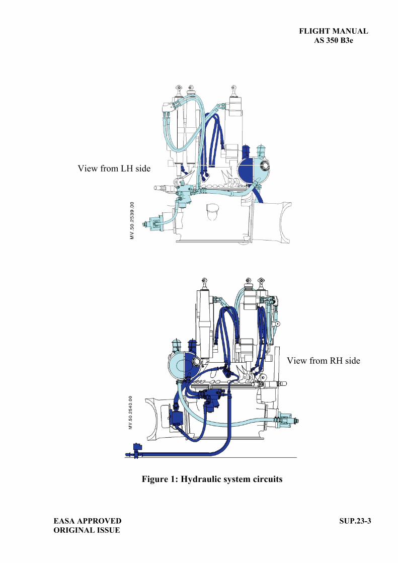
FLIGHT MANUAL
AS 350 B3e
View from LH side
View from RH side
Figure 1: Hydraulic system circuits
EASA APPROVED SUP.23-3ORIGINAL ISSUE

FLIGHT MANUAL AS 350 B3e
SUP.23-4 EASA APPROVED ORIGINAL ISSUE
Figure 2: Hydraulic system block-diagram

FLIGHT MANUAL AS 350 B3e
EASA APPROVED SUP.23-5 ORIGINAL ISSUE
2 LIMITATIONS The limitations specified in the basic flight manual and in the flight manual supplements remain applicable and are completed or modified by the following: 2.1 SERVO CONTROL FLUID
NORMAL USE
Specification Oil type NATO Code FRANCE USA UK
Notes
Synthetic oil - - MIL-H-83282 - -
2.2 HYDRAULIC SYSTEM PRESSURE
- Nominal pressure .................................................... 35 bar (507 psi), - Low pressure warning light comes on at ................ 20 bar (290 psi).
In flight the warning light must be off.
3 EMERGENCY PROCEDURES The emergency procedures specified in the basic flight manual and in the flight manual supplements remain applicable and are completed or modified by the following: 3.1 TAIL ROTOR CONTROL FAILURE Symptom: jamming of pedals or loss of effectiveness of the pedals. These
conditions make it impossible to control tail rotor thrust with the pedals.
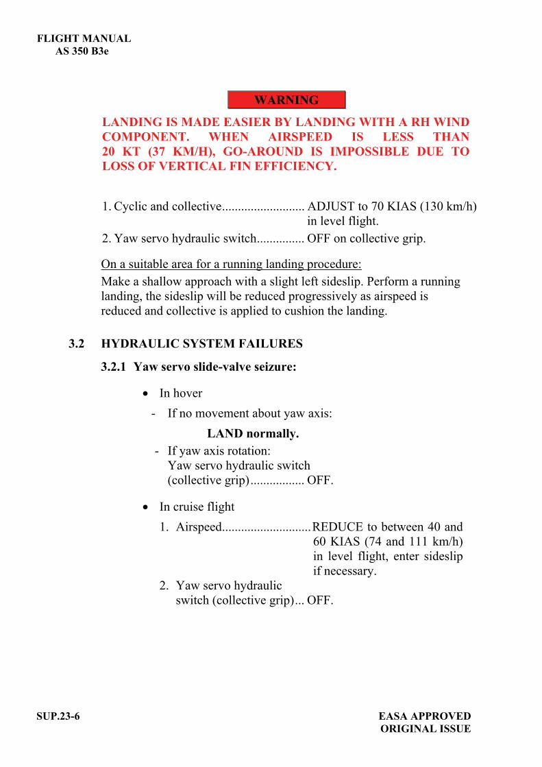
FLIGHT MANUAL AS 350 B3e
SUP.23-6 EASA APPROVED ORIGINAL ISSUE
WARNING
LANDING IS MADE EASIER BY LANDING WITH A RH WIND COMPONENT. WHEN AIRSPEED IS LESS THAN 20 KT (37 KM/H), GO-AROUND IS IMPOSSIBLE DUE TO LOSS OF VERTICAL FIN EFFICIENCY.
1. Cyclic and collective.......................... ADJUST to 70 KIAS (130 km/h)
in level flight. 2. Yaw servo hydraulic switch............... OFF on collective grip.
On a suitable area for a running landing procedure: Make a shallow approach with a slight left sideslip. Perform a running landing, the sideslip will be reduced progressively as airspeed is reduced and collective is applied to cushion the landing.
3.2 HYDRAULIC SYSTEM FAILURES
3.2.1 Yaw servo slide-valve seizure:
In hover - If no movement about yaw axis:
LAND normally. - If yaw axis rotation:
Yaw servo hydraulic switch (collective grip)................. OFF.
In cruise flight 1. Airspeed............................REDUCE to between 40 and
60 KIAS (74 and 111 km/h) in level flight, enter sideslip if necessary.
2. Yaw servo hydraulic switch (collective grip)... OFF.
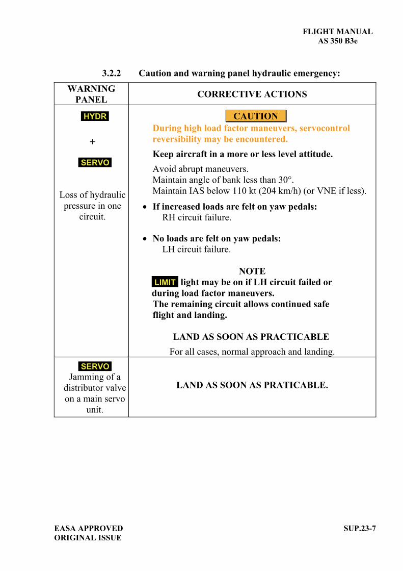
FLIGHT MANUAL AS 350 B3e
EASA APPROVED SUP.23-7 ORIGINAL ISSUE
3.2.2 Caution and warning panel hydraulic emergency: WARNING
PANEL CORRECTIVE ACTIONS
HYDR
+
SERVO
Loss of hydraulic pressure in one
circuit.
CAUTION During high load factor maneuvers, servocontrol reversibility may be encountered. Keep aircraft in a more or less level attitude. Avoid abrupt maneuvers. Maintain angle of bank less than 30°. Maintain IAS below 110 kt (204 km/h) (or VNE if less).
If increased loads are felt on yaw pedals: RH circuit failure.
No loads are felt on yaw pedals: LH circuit failure.
NOTE LIMIT light may be on if LH circuit failed or during load factor maneuvers. The remaining circuit allows continued safe flight and landing.
LAND AS SOON AS PRACTICABLE
For all cases, normal approach and landing.
SERVO Jamming of a
distributor valve on a main servo
unit.
LAND AS SOON AS PRATICABLE.

FLIGHT MANUAL AS 350 B3e
SUP.23-8 EASA APPROVED ORIGINAL ISSUE
WARNING
PANEL CORRECTIVE ACTIONS
LIMIT
Main servo unit
max. load reached.
In high speed cruise flight or steep maneuvers: 1. Collective ......................... Reduce power. 2. Cyclic................................. Reduce speed or load factor.
CONTINUE FLIGHT
4 NORMAL PROCEDURES The normal procedures specified in the basic flight manual and in the flight manual supplements remain applicable and are completed or modified by the following:
ENGINE PRESTART CHECK (paragraph 4.3.1): Replace items 13 and 14 by the following:
13. CWP lights: - With battery power ................................... CHECK:
- With EPU power....................................... CHECK: Same lights as above +
14. [SERVO TST].................................................. PRESS:
ENGINE STARTING (paragraph 4.3.2):
Replace item 6 by the following:
6. CWP ................................................................. :
GENE
FUEL P
PITOT
HORN
ENG P
MGB P
HYDR
SERVO
TWT GRIP
SERVO
ENG P
MGB PSERVO
HYDR
BATT
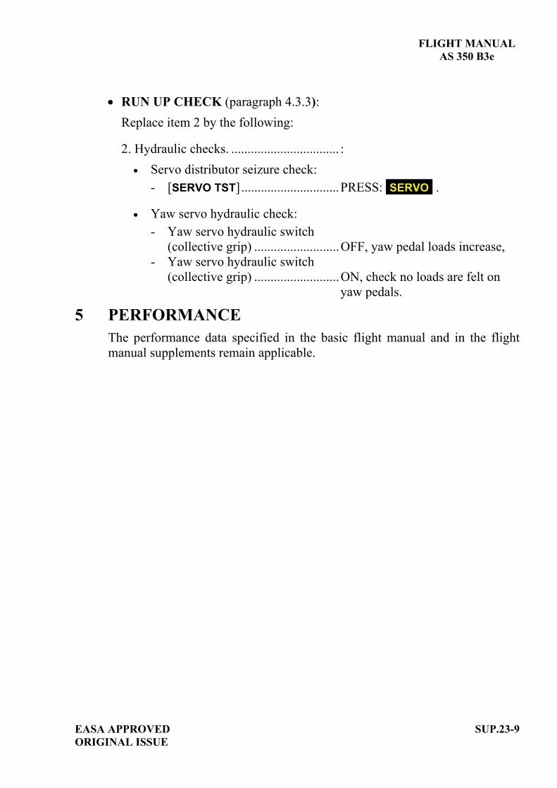
FLIGHT MANUAL AS 350 B3e
EASA APPROVED SUP.23-9 ORIGINAL ISSUE
RUN UP CHECK (paragraph 4.3.3): Replace item 2 by the following:
2. Hydraulic checks. ................................. : Servo distributor seizure check:
- [SERVO TST]..............................PRESS: SERVO .
Yaw servo hydraulic check: - Yaw servo hydraulic switch
(collective grip) ..........................OFF, yaw pedal loads increase, - Yaw servo hydraulic switch
(collective grip) ..........................ON, check no loads are felt on yaw pedals.
5 PERFORMANCE The performance data specified in the basic flight manual and in the flight manual supplements remain applicable.


EASA APPROVED ORIGINAL ISSUE
SUP.28-TITLE
FLIGHT MANUAL
AS 350 B3e
SUPPLEMENT
MAXIMUM INTERNAL GROSS WEIGHT INCREASED TO 2370 kg (5225 lb)
IMPORTANT NOTE THE INFORMATION CONTAINED HEREIN SUPPLEMENTS OR SUPERSEDES THE INFORMATION GIVEN IN THE BASIC FLIGHT MANUAL AND/OR THE SUPPLEMENTS LISTED IN SECTION SUP.0. THE EFFECTIVITY OF THE SUPPLEMENT AT THE LATEST REVISION IS SPECIFIED ON THE LIST OF EFFECTIVE PAGES.
THIS SUPPLEMENT MUST BE INCLUDED IN THE FLIGHT MANUAL WHEN THE EQUIPMENT MENTIONED ABOVE IS INSTALLED ON THE AIRCRAFT.
E U R O C O P T E R D i r e c t i o n T e c h n i q u e S u p p o r t Aéroport international Marseille-Provence 13725 Marignane Cedex – France


FLIGHT MANUAL
AS 350 B3e
EASA APPROVED A ORIGINAL ISSUE
SUP.28-A
LIST OF APPROVED EFFECTIVE PAGES - EASA CERTIFICATION REMARKS / EFFECTIVITY column:
Without indication ......Applicable to all aircraft. Clear text definition ...Effectivity (specified model or variant type ...), information
... A : Specific to EASA.
...S/N nnnn: Specific to S/N nnnn.
PAGE REV No.
REMARKS / EFFECTIVITY PAGE REV
No. REMARKS /
EFFECTIVITY SUP.28-Title 0
SUP.28-A 0 A
SUP.28-B 0 A
SUP.28-1 0
SUP.28-2 0
SUP.28-3 0
SUP.28-4 0
SUP.28-5 0
SUP.28-6 0
SUP.28-7 0
SUP.28-8 0
SUP.28-9 0
SUP.28-10 0

FLIGHT MANUAL
AS 350 B3e
SUP.28-B A
EASA APPROVEDORIGINAL ISSUE
LOG OF APPROVED NORMAL REVISIONS BASIC RFM REVISIONS - EFFECTIVITY EASA
NORMAL REVISION 0 - DECEMBER 2010 EASA approval No. 10035374 on June 17, 2011
Title New flight manual. Revised
information All pages.
Deleted information None

FLIGHT MANUAL AS 350 B3e
1 GENERAL This supplement (OP-3369) is approved on the basis of CS27 "NORMAL" rotorcraft category, it allows an increased maximum internal weight when aircraft is equipped with: - the optional high landing gear, - the optional dual hydraulic system (refer to SUP.23).
2 LIMITATIONS The limitations specified in the basic flight manual and in the flight manual supplements remain applicable and are completed or modified by the following:
2.1 TYPE OF OPERATIONS
The following is forbidden:
- Operation with jettisonable external load if the internal weight is higher than 2250 kg (4961 lb).
2.2 WEIGHT LIMITATION
- Maximum internal weight in flight................ : 2370 kg (5225 lb),
- Maximum internal weight for IGE, take-off and landing....................................... : 2370 kg (5225 lb).
EASA APPROVED ORIGINAL ISSUE
SUP.28-1

FLIGHT MANUAL AS 350 B3e
SUP.28-2 EASA APPROVEDORIGINAL ISSUE
2.2 LONGITUDINAL CG
2.3 LATERAL CG
2.3.1 Lateral CG in flight The lateral CG limits specified in the basic flight manual and in the flight manual supplements remain applicable.
2.3.2 Lateral CG at landing Internal gross weight 2250 kg (4961 lb): Maximum left CG ............. : 0.18 m (7.08 in). Maximum right CG........... : 0.14 m (5.51 in).
2250 kg (4961 lb) < Internal gross weight 2370 kg (5225 lb): Maximum left CG ............. : 0.08 m (3.15 in). Maximum right CG ........... : 0.08 m (3.15 in).
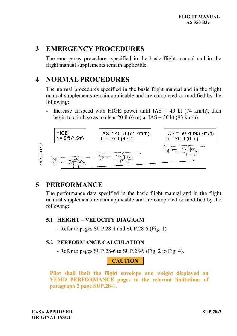
FLIGHT MANUAL AS 350 B3e
EASA APPROVED ORIGINAL ISSUE
SUP.28-3
3 EMERGENCY PROCEDURES The emergency procedures specified in the basic flight manual and in the flight manual supplements remain applicable.
4 NORMAL PROCEDURES The normal procedures specified in the basic flight manual and in the flight manual supplements remain applicable and are completed or modified by the following: - Increase airspeed with HIGE power until IAS = 40 kt (74 km/h), then
begin to climb so as to clear 20 ft (6 m) at IAS = 50 kt (93 km/h).
5 PERFORMANCE The performance data specified in the basic flight manual and in the flight manual supplements remain applicable and are completed or modified by the following:
5.1 HEIGHT – VELOCITY DIAGRAM - Refer to pages SUP.28-4 and SUP.28-5 (Fig. 1).
5.2 PERFORMANCE CALCULATION - Refer to pages SUP.28-6 to SUP.28-9 (Fig. 2 to Fig. 4).
CAUTION
Pilot shall limit the flight envelope and weight displayed on VEMD PERFORMANCE pages to the relevant limitations of paragraph 2 page SUP.28-1.

FLIGHT MANUAL AS 350 B3e
SUP.28-4 EASA APPROVEDORIGINAL ISSUE
5.3 HEIGHT – VELOCITY DIAGRAM
5.3.1 Internal gross weight 2250 kg (4961 lb): Refer to SECTION 5 Figure 5-4.
5.3.2 2250 kg (4961 lb) < Internal gross weight 2370 kg (5225 lb) The avoidance zone is defined by five points: A, B, C, D, E (refer to Figure 1).
- Point A: low hover point. Point A is at 7 ft (2.1 m) skid height at zero airspeed.
- Point B: Point B is defined by:
a constant height of 30 ft (9 m), a constant airspeed of 50 kt (93 km/h).
- Point C: Point C is defined by:
a constant height of 100 ft (30 m), a constant airspeed of 60 kt (111 km/h).
- Point D: Point D is defined by:
a variable height (700 ft height 1000 ft) depending on the altitude and on the aircraft weight as determined by line (E D),
a constant airspeed of 20 kt (37 km/h).
- Point E : Point E is defined by:
a variable height (700 ft height 1000 ft) depending on the altitude and on the aircraft weight as determined by line (E D),
a constant zero airspeed.

FLIGHT MANUAL AS 350 B3e
Figure 1
EASA APPROVED ORIGINAL ISSUE
SUP.28-5
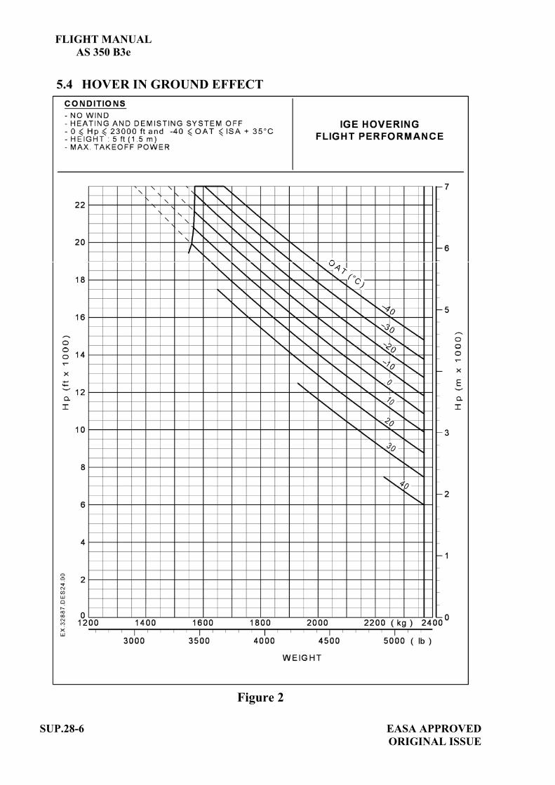
FLIGHT MANUAL AS 350 B3e
SUP.28-6 EASA APPROVEDORIGINAL ISSUE
5.4 HOVER IN GROUND EFFECT
Figure 2
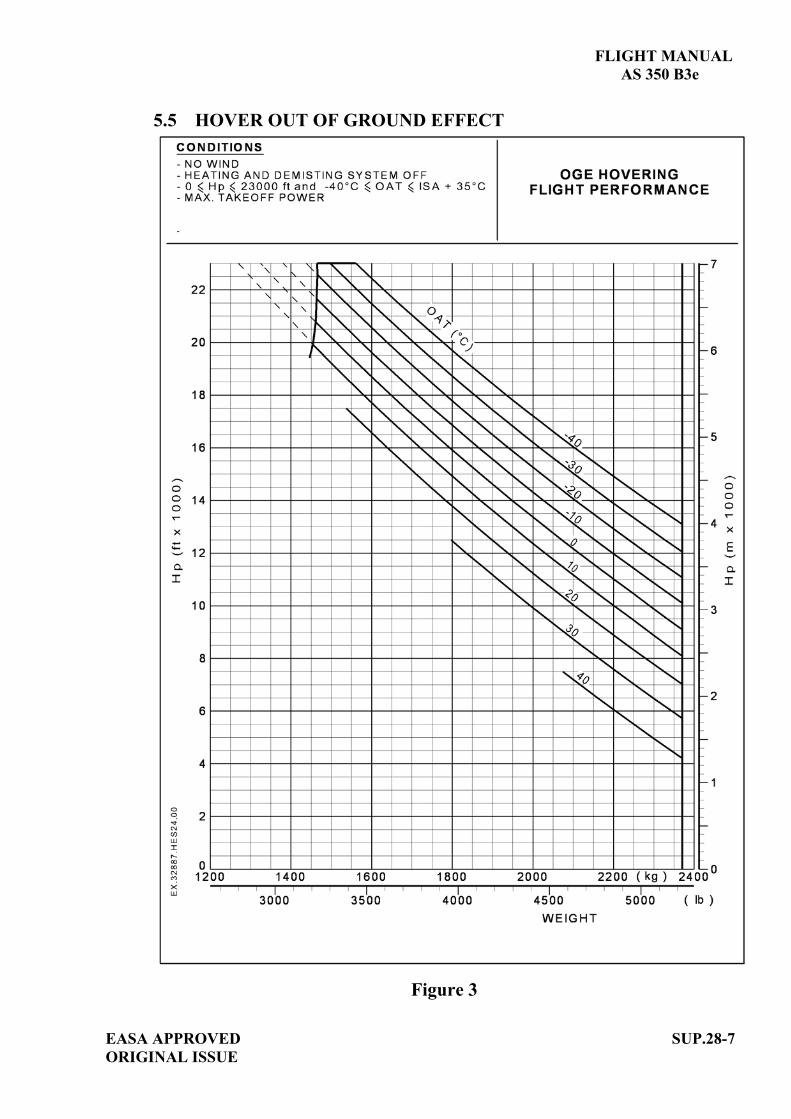
FLIGHT MANUAL AS 350 B3e
EASA APPROVED ORIGINAL ISSUE
SUP.28-7
5.5 HOVER OUT OF GROUND EFFECT
Figure 3

FLIGHT MANUAL AS 350 B3e
SUP.28-8 EASA APPROVEDORIGINAL ISSUE
5.6 CORRECTED WEIGHT
Figure 4

FLIGHT MANUAL AS 350 B3e
EASA APPROVED ORIGINAL ISSUE
SUP.28-9
5.7 RATE OF CLIMB
Figure 5

FLIGHT MANUAL AS 350 B3e
SUP.28-10 EASA APPROVEDORIGINAL ISSUE
5.8 NOISE LEVEL
Noise characteristics as defined by the conditions of Chapter 11 of ICAO Annex 16 and Appendix J of FAR Part 36 are as follows:
Flight Phase
Noise Level as per ICAO Annex 16 and
FAR Part 36 (dB SEL)
ICAO / FAR limits
(dB SEL)
Flyover at 0.9VH *With VH =131 kt (243 km/h) TAS 84.2 86.8
(*) VH = Maximum speed in level flight at power not exceeding maximum continuous power, for sea level pressure and 25°C ambient conditions at MTOW.

EASA APPROVED SUP.29-TITLE ORIGINAL ISSUE
FLIGHT MANUAL
AS 350 B3e
SUPPLEMENT
200 A STARTER GENERATOR Optional OP-3821
IMPORTANT NOTE THE INFORMATION CONTAINED HEREIN SUPPLEMENTS OR SUPERSEDES THE INFORMATION GIVEN IN THE BASIC FLIGHT MANUAL AND/OR THE SUPPLEMENTS LISTED IN SECTION SUP.0. THE EFFECTIVITY OF THE SUPPLEMENT AT THE LATEST REVISION IS SPECIFIED ON THE LIST OF EFFECTIVE PAGES.
THIS SUPPLEMENT MUST BE INCLUDED IN THE FLIGHT MANUAL WHEN THE EQUIPMENT MENTIONED ABOVE IS INSTALLED ON THE AIRCRAFT.
E U R O C O P T E R D i r e c t i o n T e c h n i q u e S u p p o r t Aéroport international Marseille-Provence 13725 Marignane Cedex – France


FLIGHT MANUAL
AS 350 B3e
EASA APPROVED A ORIGINAL ISSUE
SUP.29-A
LIST OF APPROVED EFFECTIVE PAGES - EASA CERTIFICATION REMARKS / EFFECTIVITY column:
Without indication ......Applicable to all aircraft. Clear text definition ...Effectivity (specified model or variant type ...), information
... A : Specific to EASA.
...S/N nnnn: Specific to S/N nnnn.
PAGE REV No.
REMARKS / EFFECTIVITY PAGE REV
No. REMARKS /
EFFECTIVITY SUP.29-Title 0
SUP.29-A 0 A
SUP.29-B 0 A
SUP.29-1 0

FLIGHT MANUAL
AS 350 B3e
SUP.29-B A
EASA APPROVEDORIGINAL ISSUE
LOG OF APPROVED NORMAL REVISIONS BASIC RFM REVISIONS - EFFECTIVITY EASA
NORMAL REVISION 0 - DECEMBER 2010 EASA approval No. 10035374 on June 17, 2011
Title New flight manual. Revised
information All pages.
Deleted information None

FLIGHT MANUAL AS 350 B3e
EASA APPROVED ORIGINAL ISSUE
SUP.29-1
1 GENERAL The 200 A starter generator is an optional installation. It replaces the basic 150 A starter generator and provides the aircraft with an increased electrical capacity.
2 LIMITATIONS The limitations specified in the basic flight manual and in the flight manual supplements remain applicable and are modified by the following:
Maximum current............................................. 200 A Max. continuous.
3 EMERGENCY PROCEDURES The emergency procedures specified in the basic flight manual and in the flight manual supplements remain applicable.
4 NORMAL PROCEDURES The normal procedures specified in the basic flight manual and in the flight manual supplements remain applicable.
5 PERFORMANCE The performance data specified in the basic flight manual and in the flight manual supplements remain applicable.


EASA APPROVED SUP.50-TITLE ORIGINAL ISSUE
FLIGHT MANUAL
AS 350 B3e
SUPPLEMENT
FERRY FLIGHT FUEL TANK
IMPORTANT NOTE THE INFORMATION CONTAINED HEREIN SUPPLEMENTS OR SUPERSEDES THE INFORMATION GIVEN IN THE BASIC FLIGHT MANUAL AND/OR THE SUPPLEMENTS LISTED IN SECTION SUP.0. THE EFFECTIVITY OF THE SUPPLEMENT AT THE LATEST REVISION IS SPECIFIED ON THE LIST OF EFFECTIVE PAGES.
THIS SUPPLEMENT MUST BE INCLUDED IN THE FLIGHT MANUAL WHEN THE EQUIPMENT MENTIONED ABOVE IS INSTALLED ON THE AIRCRAFT.
E U R O C O P T E R D i r e c t i o n T e c h n i q u e S u p p o r t Aéroport international Marseille-Provence 13725 Marignane Cedex – France


FLIGHT MANUAL
AS 350 B3e
EASA APPROVED A ORIGINAL ISSUE
SUP.50-A
LIST OF APPROVED EFFECTIVE PAGES - EASA CERTIFICATION REMARKS / EFFECTIVITY column:
Without indication ......Applicable to all aircraft. Clear text definition ...Effectivity (specified model or variant type ...), information
... A : Specific to EASA.
...S/N nnnn: Specific to S/N nnnn.
PAGE REV No.
REMARKS / EFFECTIVITY PAGE REV
No. REMARKS /
EFFECTIVITY SUP.50-Title 0
SUP.50-A 0 A
SUP.50-B 0 A
SUP.50-1 0
SUP.50-2 0
SUP.50-3 0

FLIGHT MANUAL
AS 350 B3e
SUP.50-B A
EASA APPROVEDORIGINAL ISSUE
LOG OF APPROVED NORMAL REVISIONS BASIC RFM REVISIONS - EFFECTIVITY EASA
NORMAL REVISION 0 - DECEMBER 2010 EASA approval No. 10035374 on June 17, 2011
Title New flight manual. Revised
information All pages.
Deleted information None

FLIGHT MANUAL AS 350 B3e
EASA APPROVED SUP.50-1 ORIGINAL ISSUE
1 GENERAL The use of this installation is subject to the approval of the operational authorities concerned. To increase the maximum range of the helicopter, a specific ferry flight fuel tank can be installed transversally in the rear cabin area. The installation consists essentially of: - a 475 liter (125 US gal – 104.5 UK gal) removable tank with negligible
unusable fuel quantity, - a vent line, - a fuel transfer pipe with a manually actuated valve between the ferry tank
and helicopter fuel tank. The fuel is transferred by gravity into the helicopter fuel tank.
2 LIMITATIONS The limitations specified in the basic flight manual and in the flight manual supplements remain applicable and are completed or modified by the following:
2.1 OPERATIONS AUTHORIZED This installation is to be used only for ferry flight, provided such operation is permitted by the appropriate aviation authorities of the country concerned.
2.2 CREW LIMITATION Only persons essential to the mission shall be allowed on board the aircraft.
2.3 FERRY TANK FUEL WEIGHT LIMITATION The weight of fuel that be carried in the ferry tank will depend on the overall loading of the helicopter. Refer to SECTION 6 of the basic flight manual to determine aircraft CG.
CAUTION
The maximum ferry tank fuel weight must be determined carefully to remain within the forward CG limit given by SECTION 2 of the basic flight manual specifically with a full main tank.
2.4 SPECIFIC ITEMS Smoking in cabin is prohibited. Maximum ventilation of the cabin is to be ensured.
FLIGHT MANUAL AS 350 B3e
SUP.50-2 EASA APPROVED ORIGINAL ISSUE
3 EMERGENCY PROCEDURES The emergency procedures specified in the basic flight manual and in the flight manual supplements remain applicable and are completed or modified by the following:
Fuel leak in the cabin: LAND AS SOON AS POSSIBLE
4 NORMAL PROCEDURES The normal procedures specified in the basic flight manual and in the flight manual supplements remain applicable and are completed or modified by the following:
Checks before filling ferry tank: . Ferry tank ............................................ Condition, attachment, . Ferry tank vent line .............................. Installed and correctly secured, . Transfer valve. ..................................... Closed, . Max. ferry tank fuel quantity ............... Determined, refer to SECTION 6
of the basic flight manual to determine aircraft CG.
Filling procedure: . Main fuel tank ..................................... Fill, . Ferry tank ............................................. Fill with quantity previously
determined. In flight transfer procedure:
Takeoff and cruise flight: . Transfer valve ........................................ Maintain closed until main fuel
gauge reads 80 %. When fuel gauge reads 80 % : . Transfer valve ........................................ Open, . Fuel transfer ........................................... Check effective: (fuel gauge
indicator is moving). CAUTION
If fuel transfer is not operative, land before the fuel gauge indicator reads 60%. Failure to land above 60% may result in CG exceeding the approved limits.

FLIGHT MANUAL AS 350 B3e
EASA APPROVED SUP.50-3 ORIGINAL ISSUE
The fuel level in the two tanks will be equal when the ferry tank quantity is approximately 300 l (79.2 US gal – 66.0 UK gal). If there is a difference in fuel level, fuel will be transferred and the levels will be balanced within 10 min. When the fuel levels are balanced in the two tanks, the quantity corresponding to the gauge reading is:
Fuel gauge reading
(%)
90
80
70
60
50
40
30
20
Liters 805 705 605 505 405 305 205 105 USG 212 186 159 133 107 80 54 27
V O L U M E
Imp. G
176 154 132 110 88 66 45 23
When the gauge reads 20 % the ferry tank is empty and the quantity of fuel remaining in the main tank is 105 l (27 US gal – 23 UK gal).
5 PERFORMANCE The performance data specified in the basic flight manual and in the flight manual supplements remain applicable.


EASA APPROVED ORIGINAL ISSUE
SUP.52-TITLE
FLIGHT MANUAL
AS 350 B3e
SUPPLEMENT
"BAMBI BUCKET" MODEL 2732S
IMPORTANT NOTE THE INFORMATION CONTAINED HEREIN SUPPLEMENTS OR SUPERSEDES THE INFORMATION GIVEN IN THE BASIC FLIGHT MANUAL AND/OR THE SUPPLEMENTS LISTED IN SECTION SUP.0. THE EFFECTIVITY OF THE SUPPLEMENT AT THE LATEST REVISION IS SPECIFIED ON THE LIST OF EFFECTIVE PAGES.
THIS SUPPLEMENT MUST BE INCLUDED IN THE FLIGHT MANUAL WHEN THE EQUIPMENT MENTIONED ABOVE IS INSTALLED ON THE AIRCRAFT.
E U R O C O P T E R D i r e c t i o n T e c h n i q u e S u p p o r t Aéroport international Marseille-Provence 13725 Marignane Cedex – France


FLIGHT MANUAL
AS 350 B3e
EASA APPROVED A ORIGINAL ISSUE
SUP.52-A
LIST OF APPROVED EFFECTIVE PAGES - EASA CERTIFICATION REMARKS / EFFECTIVITY column:
Without indication ......Applicable to all aircraft. Clear text definition ...Effectivity (specified model or variant type ...), information
... A : Specific to EASA.
...S/N nnnn: Specific to S/N nnnn.
PAGE REV No.
REMARKS / EFFECTIVITY PAGE REV
No. REMARKS /
EFFECTIVITY SUP.52-Title 0
SUP.52-A 0 A
SUP.52-B 0 A
SUP.52-1 0
SUP.52-2 0
SUP.52-3 0

FLIGHT MANUAL
AS 350 B3e
SUP.52-B A
EASA APPROVEDORIGINAL ISSUE
LOG OF APPROVED NORMAL REVISIONS BASIC RFM REVISIONS - EFFECTIVITY EASA
NORMAL REVISION 0 - DECEMBER 2010 EASA approval No. 10035374 on June 17, 2011
Title New flight manual. Revised
information All pages.
Deleted information None

FLIGHT MANUAL AS 350 B3e
EASA APPROVED ORIGINAL ISSUE
SUP.52-1
1 GENERAL
The use of this installation is subject to the approval of the operational authorities concerned. The "BAMBI BUCKET" model 2732S installation is a fire-fighting system used to carry and jettison water or other liquids in flight. Maximum capacity: 1225 litres. The installation is composed of a bucket secured to the external load carrying device via a shackle (refer to SUP.13.1 or SUP.13.2). The bucket is filled by plunging it into water (swimming pool, sea, lake, etc.). The "BAMBI BUCKET" enables the water load to be released in a single drop. A foam injection system "SACKSAFOAM" (P/N: SF02-2044) can be installed as an option. 1.1 GENERAL DESCRIPTION
The controls include: - A [SLING] pushbutton located on the SCU for switching on the
installation. - A pushbutton (1) located on the cyclic grip is used to release the
contents of the bucket. - A pushbutton (2) located on the cyclic grip is used to electrically
release the entire load suspended from the sling hook. - A trigger (3) located on the collective lever is used to mechanically
release the entire load suspended from the sling hook.
Figure 1: Release controls

FLIGHT MANUAL AS 350 B3e
SUP.52-2 EASA APPROVEDORIGINAL ISSUE
- A load indicator indicates the weight suspended from the hook (refer to SUP.13.1 or SUP.13.2).
- A control unit located on the instrument panel or the console is used to control the optional foam injection system.
2 LIMITATIONS
The limitations specified in the basic flight manual and in the flight manual supplements remain applicable and are completed or modified by the following: Speed limitations: - Empty bucket .......................................: VNE = 90 kt (167 km/h - 104 MPH). - Bucket full or partially filled ...............: VNE = 80 kt (148 km/h - 92 MPH).
3 EMERGENCY PROCEDURES
The emergency procedures specified in the basic flight manual and in the flight manual supplements remain applicable and are completed or modified by the following: 3.1 WATER EMERGENCY JETTISON
If it is impossible to jettison the contents of the "BAMBI BUCKET" via the electrical control on the cyclic grip, the pilot may place the bucket (filled or empty) on the ground as he would do with a load on the cargo sling. The ground staff may then unhook the bucket via the load release device.
3.2 BUCKET EMERGENCY JETTISON If there is a problem on the helicopter requiring bucket jettison, the bucket (filled or empty) may be released via the cargo sling electrical or mechanical release controls. In order to release the bucket, it is recommended to enter a right hand turn with a slight load factor.

FLIGHT MANUAL AS 350 B3e
EASA APPROVED ORIGINAL ISSUE
SUP.52-3
4 NORMAL PROCEDURES The normal procedures specified in the basic flight manual and in the flight manual supplements remain applicable and are completed or modified by the following: 4.1 CHECK BEFORE TAKEOFF
- Check that the bucket is correctly secured. - Check that the manufacturer's plate on the shackle and the ballast inside
the bucket are facing forward.
5 PERFORMANCE For weights with external load > maximum weight specified in the limitations section of the basic flight manual, refer to SECTION 5.1, "REGULATORY PERFORMANCE", page 5-11 of the basic flight manual; the curves are plotted in dotted lines on figure 5-6.

EASA APPROVED ORIGINAL ISSUE
SUP.55-TITLE
FLIGHT MANUAL
AS 350 B3e
SUPPLEMENT
GARMIN GNS 430/430W GPS
IMPORTANT NOTE THE INFORMATION CONTAINED HEREIN SUPPLEMENTS OR SUPERSEDES THE INFORMATION GIVEN IN THE BASIC FLIGHT MANUAL AND/OR THE SUPPLEMENTS LISTED IN SECTION SUP.0. THE EFFECTIVITY OF THE SUPPLEMENT AT THE LATEST REVISION IS SPECIFIED ON THE LIST OF EFFECTIVE PAGES.
THIS SUPPLEMENT MUST BE INCLUDED IN THE FLIGHT MANUAL WHEN THE EQUIPMENT MENTIONED ABOVE IS INSTALLED ON THE AIRCRAFT.
E U R O C O P T E R D i r e c t i o n T e c h n i q u e S u p p o r t Aéroport international Marseille-Provence 13725 Marignane Cedex – France


FLIGHT MANUAL
AS 350 B3e
EASA APPROVED A ORIGINAL ISSUE
SUP.55-A
LIST OF APPROVED EFFECTIVE PAGES - EASA CERTIFICATION REMARKS / EFFECTIVITY column:
Without indication ......Applicable to all aircraft. Clear text definition ...Effectivity (specified model or variant type ...), information
... A : Specific to EASA.
...S/N nnnn: Specific to S/N nnnn.
PAGE REV No.
REMARKS / EFFECTIVITY PAGE REV
No. REMARKS /
EFFECTIVITY SUP.55-Title 0
SUP.55-A 0 A
SUP.55-B 0 A
SUP.55-1 0
SUP.55-2 0
SUP.55-3 0
SUP.55-4 0
SUP.55-5 0
SUP.55-6 0
SUP.55-7 0

FLIGHT MANUAL
AS 350 B3e
SUP.55-B A
EASA APPROVEDORIGINAL ISSUE
LOG OF APPROVED NORMAL REVISIONS BASIC RFM REVISIONS - EFFECTIVITY EASA
NORMAL REVISION 0 - DECEMBER 2010 EASA approval No. 10035374 on June 17, 2011
Title New flight manual. Revised
information All pages.
Deleted information None
FLIGHT MANUAL AS 350 B3e
EASA APPROVED SUP.55-1 ORIGINAL ISSUE
1 GENERAL The use of this installation is subject to the approval of the operational authorities concerned. The “GNS 430/430W” includes a VHF COM transceiver, a VOR/ILS receiver and a GPS navigation system. The GARMIN “GNS 430/430W” GPS system complies with the requirements as a supplement to VFR navigation.
Abbreviations BRG : Bearing to waypoint. CDI : Course Deviation Indicator. DTK : Desired Track. DIS : Distance to waypoint. ETE : Estimated Time En-route. GS : Ground Speed. HSI : Horizontal Situation Indicator OBS : Omni Bearing Selector RAIM : Receiver Autonomous Integrity Monitoring. TRK : Track. XTK : Cross Track error, the cross track error has a manual or
an automatic adjustable scale on the CDI.
2 LIMITATIONS The limitations specified in the basic flight manual and in the flight manual supplements remain applicable and are completed or modified by the following: 2.1 PILOT'S GUIDE
2.1.1 GNS 430 pilot's guide The Pilot's Guide operating manual (Part number 190-00140-00, Rev. F dated July 2000 or later revision) must be on board the aircraft and readily available to the pilot.

FLIGHT MANUAL AS 350 B3e
SUP.55-2 EASA APPROVED ORIGINAL ISSUE
2.1.2 GNS 430W pilot's guide The Pilot's Guide operating manual (Part number 190-00356-00, Rev.C dated March 2008 or later revision) must be on board the aircraft and readily available to the pilot.
2.2 SOFTWARE VERSIONS 2.2.1 GNS 430 Software versions
The GNS 430 must be loaded with the following or later approved software versions:
GNS 430 sub-system Software version
Main GPS COMM VOR/LOC G/S
2.25 2.11 5.00 3.01 2.03
The main software version is displayed on the GNS 430 self-test page 5 seconds after power-on. The other system software versions can be checked on the AUX group sub-page 2: SOFTWARE/DATABASE Ver. From main software version 5.01, a TAWS (TERRAIN) function has been added to the GNS 430. USING THE TAWS FUNCTION OF THE GPS IS PROHIBITED. Consequently, this function is de-activated by configuration and shall remain so.
2.2.2 GNS 430W Software versions The GNS 430W must be loaded with the following or later approved software versions:
GNS 430W sub-system Software version
Main GPS COMM VOR/LOC G/S
3.10 3.1 7.00 5.02 4.00

FLIGHT MANUAL AS 350 B3e
EASA APPROVED SUP.55-3 ORIGINAL ISSUE
The main software version is displayed on the GNS 430W self-test page 5 seconds after power-on. The other system software versions can be checked on the AUX group sub-page 2: SOFTWARE/DATABASE Ver.
USING THE TAWS FUNCTION OF THE GPS IS PROHIBITED. Consequently, this function is de-activated by configuration and shall remain so.
The GPS receiver is capable of tracking SBAS (WAAS, EGNOS) satellites. USING THE SBAS MODE OF THE GPS IS PROHIBITED. Consequently, SBAS (WAAS, EGNOS) operation is de-activated in set-up sub-group page 2 and shall remain so.
2.3 OPERATION The use of the GPS is restricted to VFR flight only. All the navigation means required for each route phase of the intended flight must be available and serviceable. As the database is not guaranteed, the crew must check, before the flight if possible, the validity and the accuracy of the database information by reference to the official documentation. Before starting navigation, the crew must read the GNS 430/430W self-test messages to check that all necessary validities are present.
2.4 PLACARDS
Location: Next to the GNS 430/430W on the instrument panel.
GPS OPERABLE IN VFR CONDITIONS ONLY
GPS UTILISABLE EN VFR UNIQUEMENT

FLIGHT MANUAL AS 350 B3e
SUP.55-4 EASA APPROVED ORIGINAL ISSUE
3 EMERGENCY PROCEDURES The emergency procedures specified in the basic flight manual and in the flight manual supplements remain applicable and are completed or modified by the following: 3.1 GPS FAILURES
FAILURES CORRECTIVE ACTIONS
NAV flag on HSI (or external CDI).
+
MSG
[MSG] key........................Press and check message.
1. GPS navigation data not available or invalid. 2. RAIM POSITION WARNING.
In both cases, use remaining operational means of navigation (GNS 430/430W VOR or any other available means).
CONTINUE THE FLIGHT
MSG
+ INTEG
[MSG] key........................Press and check message.
RAIM IS NOT AVAILABLE Revert to other operational means of navigation (GNS 430/430W VOR or any other available means) approved for the route and flight phase. During En-route phase, GPS navigation can still be used provided the position can be checked with other means of navigation at least every 15 min.
CONTINUE THE FLIGHT
NOTE Bottom row key [MSG] is used on GNS 430/430W to display the message.
FLIGHT MANUAL AS 350 B3e
EASA APPROVED SUP.55-5 ORIGINAL ISSUE
4 NORMAL PROCEDURES The normal procedures specified in the basic flight manual and in the flight manual supplements remain applicable and are completed or modified by the following: 4.1 OPERATING PROCEDURES
The detailed operating procedures are described in the Pilot's Guide referenced in paragraph 2.1 of this supplement.
NOTE 1 Use of the VHF frequencies listed below may degrade GPS receiver operation after 10 to 15 seconds of transmission time, returning to normal operation a few seconds after transmission ends. Frequencies = 121.150 / 121.175 / 121.200 / 131.200 / 131.250 / 131.275 and 131.300 MHz.
NOTE 2 Correct operation of the GPS is not guaranteed for cabin temperatures below - 20°C.
4.2 CONTROLS AND INDICATORS The GNS 430/430W GPS navigation system provides the following information to the pilot's HSI or external CDI: - XTK - TO / FROM - Validity flag
NOTE 1 XTK full scale deviation is the same for the HSI, or external CDI, and the GNS 430/430W integrated CDI. Default setting is 5 NM (meaning that full deviation is achieved when XTK reaches 5 NM) except within 30 NM range of the departure/destination airfield. Within 30 NM of the destination airfield, the full scale deviation gradually ramps from 5 to 1 NM. Likewise, upon departure, default setting is 1 NM gradually increasing up to 5 NM beyond 30 NM from the departure airfield.

FLIGHT MANUAL AS 350 B3e
SUP.55-6 EASA APPROVED ORIGINAL ISSUE
NOTE 1 (Cont’d) XTK scale is also selectable by the pilot. However, the GNS 430/430W will automatically select the lowest value between the default setting and the value selected by the pilot. Current selected scale is displayed on either side of the GNS 430/430W's CDI. Recommended full-scale value for helicopter "En-route" navigation is 1 NM.
NOTE 2 The HSI or CDI course is not automatically slaved to the desired track (DTK). Consequently, when GPS navigation is selected,( GPS on GNS 430/430W screen) as HSI or external CDI navigation source, the course pointer on the HSI or course selector on the external CDI must be manually set to the DTK indicated by the GNS 430/430W. Particular attention is required during automatic navigation leg changes and subsequent change of DTK. However, if the course selected on pilot's HSI or external CDI differs from the DTK by more than 10°, the MSG annunciator will flash and the message Set course to xxx will be displayed on the GNS 430/430W "MSG" page.
NOTE 3 Pressing the [CDI] key on the GNS 430/430W toggles HSI or external CDI navigation source between GPS and VOR/ILS ( GPS or VLOC displayed above [CDI] key).
NOTE 4 Pressing the [OBS] key on the GNS 430/430W toggles between manual mode (OBS mode) and automatic sequencing of waypoints. Activating OBS mode, indicated by the OBS annunciator above the [OBS] key, holds current active waypoint as the navigation destination and prevents the GNS 430/430W from sequencing to the next waypoint. In OBS mode, the DTK to/from the active waypoint is controlled via the pilot's HSI course pointer or external CDI course selector. The "GNS 430/430W" GPS navigation system is also associated with a two-label indicator on the pilot's instrument panel (If installed):
Waypoint Alert light
GNS 430/430W Message Alert
WPT
MSG

FLIGHT MANUAL AS 350 B3e
EASA APPROVED SUP.55-7 ORIGINAL ISSUE
5 PERFORMANCE The performance data specified in the basic flight manual and in the flight manual supplements remain applicable.


EASA APPROVED SUP.56-TITLE ORIGINAL ISSUE
FLIGHT MANUAL
AS 350 B3e
SUPPLEMENT
ABSEILING INSTALLATION
IMPORTANT NOTE THE INFORMATION CONTAINED HEREIN SUPPLEMENTS OR SUPERSEDES THE INFORMATION GIVEN IN THE BASIC FLIGHT MANUAL AND/OR THE SUPPLEMENTS LISTED IN SECTION SUP.0. THE EFFECTIVITY OF THE SUPPLEMENT AT THE LATEST REVISION IS SPECIFIED ON THE LIST OF EFFECTIVE PAGES.
THIS SUPPLEMENT MUST BE INCLUDED IN THE FLIGHT MANUAL WHEN THE EQUIPMENT MENTIONED ABOVE IS INSTALLED ON THE AIRCRAFT.
E U R O C O P T E R D i r e c t i o n T e c h n i q u e S u p p o r t Aéroport international Marseille-Provence 13725 Marignane Cedex – France


FLIGHT MANUAL
AS 350 B3e
EASA APPROVED A ORIGINAL ISSUE
SUP.56-A
LIST OF APPROVED EFFECTIVE PAGES - EASA CERTIFICATION REMARKS / EFFECTIVITY column:
Without indication ......Applicable to all aircraft. Clear text definition ...Effectivity (specified model or variant type ...), information
... A : Specific to EASA.
...S/N nnnn: Specific to S/N nnnn.
PAGE REV No.
REMARKS / EFFECTIVITY PAGE REV
No. REMARKS /
EFFECTIVITY SUP.56-Title 0
SUP.56-A 0 A
SUP.56-B 0 A
SUP.56-1 0
SUP.56-2 0

FLIGHT MANUAL
AS 350 B3e
SUP.56-B A
EASA APPROVEDORIGINAL ISSUE
LOG OF APPROVED NORMAL REVISIONS BASIC RFM REVISIONS - EFFECTIVITY EASA
NORMAL REVISION 0 - DECEMBER 2010 EASA approval No. 10035374 on June 17, 2011
Title New flight manual. Revised
information All pages.
Deleted information None
FLIGHT MANUAL AS 350 B3e
EASA APPROVED SUP.56-1 ORIGINAL ISSUE
1 GENERAL The use of this installation is subject to the approval of the operational authorities concerned. This installation (Modification 355P84.0080) allows trained personnel to perform abseiling. It consists of two rings secured to the cabin floor in front of the passenger seats and of a protection for the lower rail of each sliding door.
2 LIMITATIONS The limitations specified in the basic flight manual and in the flight manual supplements remain applicable and are completed or modified by the following: - Abseiling is limited to hover flight. After completion of the abseiling operation, transition to forward flight or
landing is prohibited with the ropes extended.
- The load on the abseiling installation is limited to 120 kg (265 lb) per ring. A placard located near to each ring indicates the maximum load.
3 EMERGENCY PROCEDURES The emergency procedures specified in the basic flight manual and in the flight manual supplements remain applicable.

FLIGHT MANUAL AS 350 B3e
SUP.56-2 EASA APPROVED ORIGINAL ISSUE
4 NORMAL PROCEDURES
The normal procedures specified in the basic flight manual and in the flight manual supplements remain applicable and are completed or modified by the following:
- Before takeoff, determine the weight and CG conditions which will prevail during the mission, knowing that the load on the abseil ropes is located at: . 2.24 m (88 in) from the longitudinal datum, . 1.09 m (43 in) from the aircraft centerline.
5 PERFORMANCE
The performance data specified in the basic flight manual and in the flight manual supplements remain applicable.