Embed Size (px)
Citation preview

GENERAL
ASA6 - ID-400
ASA6 ID-400
Motor Voltage–12 volt Motor Voltage - 12V DC Absorbed Power –70 watts Motor Inputs - OneSpeed–10m/min Battery Charger – Inbuilt Maximum Thrust –390N Receiver – Inbuilt Protection Level – IP55 Limit Switches –YesDuty Cycle–80% Pedestrian Input –Yes (NO)Dimensions –210L x190W x 330H Start Input - Yes (NO)Current Absorbed –2.3A Stop Input –Yes (NC)
Photocell Input –Two (NC)Maximum Leaf Weight –600KgTorque–13.5 Nm Slow Speed Regulator –Yes
Solar power notes and connections on the last page.
There is a video on the ASA6 online at -
www.automaticsolutions.com.au/assetshttp://www.automaticsolutions.com.au/assets/videos/asa6-id400/asa6-id400.html
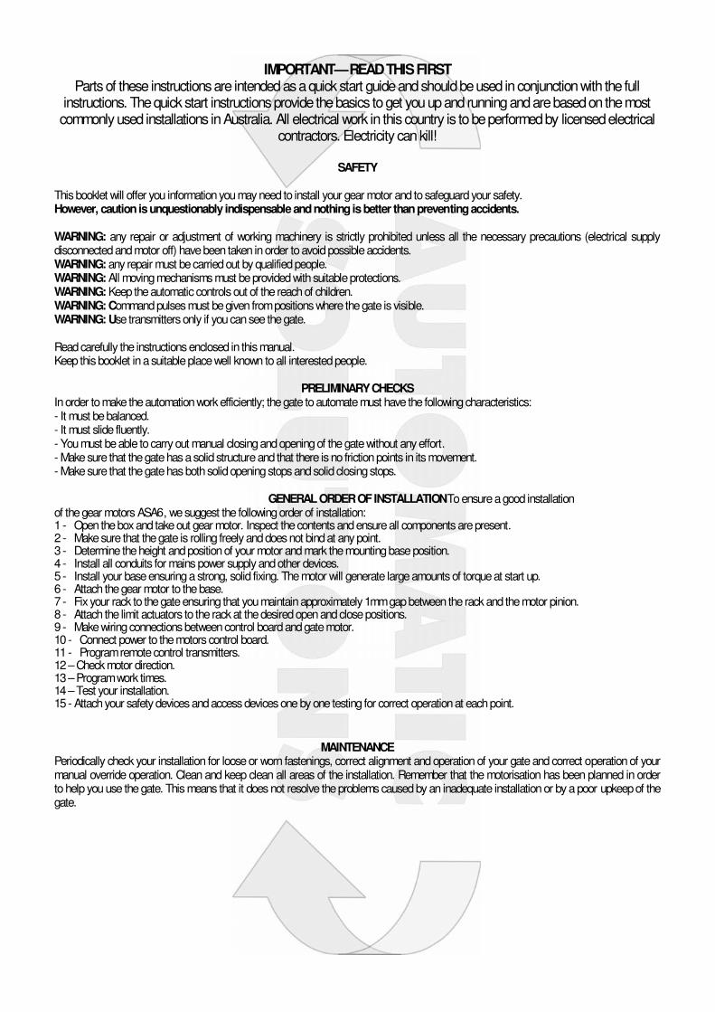
IMPORTANT—READ THIS FIRSTParts of these instructions are intended as a quick start guide and should be used in conjunction with the full
instructions. The quick start instructions provide the basics to get you up and running and are based on the mostcommonly used installations in Australia. All electrical work in this country is to be performed by licensed electrical
contractors. Electricity can kill!
SAFETY
This booklet will offer you information you may need to install your gear motor and to safeguard your safety.However, caution is unquestionably indispensable and nothing is better than preventing accidents.
WARNING: any repair or adjustment of working machinery is strictly prohibited unless all the necessary precautions (electrical supplydisconnected and motor off) have been taken in order to avoid possible accidents.WARNING: any repair must be carried out by qualified people.WARNING: All moving mechanisms must be provided with suitable protections.WARNING: Keep the automatic controls out of the reach of children.WARNING: Command pulses must be given from positions where the gate is visible.WARNING: Use transmitters only if you can see the gate.
Read carefully the instructions enclosed in this manual.Keep this booklet in a suitable place well known toall interested people.
PRELIMINARY CHECKSIn order to make the automation work efficiently; the gate to automate must have the following characteristics:- It must be balanced.- It must slide fluently.- You must be able to carry out manual closing and opening of the gate without any effort.- Make sure that the gate has a solid structure and that there is no friction points in its movement.- Make sure that the gate hasboth solid opening stops and solid closing stops.
MAINTENANCEPeriodically check your installation for loose or worn fastenings, correct alignment and operation of your gate and correct operation of yourmanual override operation. Clean and keep clean all areas of the installation. Remember that the motorisation has been planned in orderto help you use the gate. This means that it does not resolve the problems caused by an inadequate installation or by a poor upkeep of thegate.
GENERALORDER OFINSTALLATIONToensurea good installation of the gear motors ASA6, we suggest the following order of installation:1 - Open the box and take out gear motor. Inspect the contents and ensure all components are present.2 - Make sure that the gate is rolling freely and does not bind at any point.3 - Determine the height andposition of your motor and mark the mounting base position.4 - Install all conduits for mains power supply and other devices.5 - Install your base ensuring a strong, solid fixing. The motor will generate large amounts of torque at start up.6 - Attach the gear motor to thebase.7 - Fix your rack to the gate ensuring that you maintain approximately 1mm gap between the rack and the motor pinion.8 - Attach the limit actuators to the rack at the desired open and close positions.9 - Make wiring connections between control board and gate motor.10 - Connect power to the motors control board.11 - Program remote control transmitters.12–Check motor direction.13–Program work times.14–Test your installation.15 - Attach your safety devices and access devices one by one testing for correct operation at each point.

INSTALLMOTOR BASE PLATEThe position of the motor base plate will vary with each installation but in general thebase plate needs to be 78mm from the side face of your gate. The height of the platewill be determined by your site conditions and gate structure.
The motor will generate a large amount of force on starting and for this reason it isimportant that the motor base is anchored securely to the ground. A few methods ofsecuring are detailed below.
• On new installs with no track you can weld supports and attach your base tothe track before concreting the track in.
• If the track exists but a foundation is required for the motor base, thenweld acouple of scrap steel lengths to the base before fixing in concrete. This will ensure that the base does not move in the concrete.
• If you have an existing strong foundation use strong purpose made fasteners to secure the base to the foundation.
IMPORTANT: In all cases install all conduits before securing your motorbase. Once the base is installed it is much more difficult to install conduits.
BOLT DOWN MOTOROnce your motor base is installed and due time has been given forfoundations to dry or settle you can attach your motor to the motor base withthe bolts provided.
INSTALL RACKIf youhave carefully planned your motor base position then it should bepossible to sit a length of rack onto the motor pinion and the rack fixing tabsshould be in good position against the back face of the gate. Yes? Good.Put the motor in manual mode using your manual override key – insert thekey in the keyway and turn –pull the manual override lever out to 90degrees. You are now in manual mode and the pinion will rotate freely.
Open thegate fully –positionyour first length of rack on thepinionandagainst the gate –get this first length roughlylevel and attach this length attwo end points –adjust theheight of this length so thatthere is approximately a 1mmgap between the rack and thepinion–move the gatebackwards and forwards along
this length and check for no tight spots or binding –now install the next length in the same way (if the rack has location lugs this helps toposition one end and you only need to position the other end and fix, if not you can use another length upside down and a clamp to holdthe new length at the correct height and position) - when all lengths are attached and you are happy that you have no tight spots you canset the remaining fasteners on the rack.
INSTALL GATE STOPSThis is a critical point in ensuring long trouble free operation of your automation system,yet it is relatively simple. Each gate must have a positive and well secured opening stopand closing stop. There are a range of stops available over the counter or you can makethem yourself but the critical point is that the stops must be well secured as the gearmotors will exert quite a deal of force on them during programming. In summary when yourgate/s open they must hit a positive stop point that stop the gate/s from opening anyfurther and the same at the closed point.
ATTACH LIMIT ACTUATORSNow attach your limit actuators to the rack in the desired opening and closing position. Theactuators should be positioned to hit the limit spring and activate the switch before hitting
the opening and closing stops. If after programming the gate drives hard to either stop adjust the actuators and re program so that the gatedoes not hit the stops.
ASA6 SLIDING GATE MOTOR INSTALLATION

Manuale istruzioniInstructions ManualLivret d’instruction
Rev. 1
ID-400I
GB
F
Control unit low voltageFor sliding Gate

I
GB
Important: Read carefully this manual before the installation. This manual is integral part of your product, keep it for reference.
Warnings: First of all verify that this product is suitable for the installation. Read carefully technical characteristic before the installation.Installation of this control unit must be properly done by qualified installers, following rules and regulations of installation country.It's mandatory do periodic maintenance each 6 month. Maintenance or repairing must be done by qualified Technicians. Turn power off before maintenance or repairing.This device is intended for gate automation, any other applications is strongly advised.Not respecting of rules may cause serious damage to peoples, animals, things. Manufacturer discharges all responsibility for missed respect of rules.Don't let this control unit unattended or where children can reach
Preliminary checking: Before to install this control unit, verify that all the connected devices respect the technical characteristics mentioned in the table which follows. Verify that a working and suitable life switch is installed upline the installation. Verify that cables composing the installation, are suitable for it.
Important : Avant toute installation lire attentivement ce manuel. Cette notice fait partie intégrante de votreproduit. Conservez-la soigneusement en vue de toute consultation ultérieure..
Avertissements généraux: Vérifier avant travaux que ce produit est adapté à votre portail et votre emplacement. L’installation de cet automatisme de portail requiert des compétences en matière d’électricité, l’installateur doit respecter les normes en vigueur d’installation, vérifier la conformité de l’ensemble automatisme de portail, protéger et informer les utilisateurs de tout risque, installer des dispositifs de contrôle et de sécurité.Une vérification et un entretien périodique de l’installation est indispensable tous les 6 mois. L’utilisateur doit s’abstenir de faire toute tentative de réparation pour remédier à un défaut, et demander l’intervention d’un personnel qualifié. Couper systématiquement l’alimentation avant toute intervention de réparation, de raccordement ou de maintenance.Cet automatisme doit être utilisé exclusivement pour un usage domestique.Une installation ne respectant pas ces normes est susceptible de provoquer des dommages aux personnes, animaux et biens dont le constructeur n’est pas tenu pour responsable.
Importante: Prima di procedere all'installazione, leggere attentamente questo manuale. Queste istruzioni sono parte integrante del vostro prodotto, conservarle in un luogo asciutto per poterle consultarle in ogni momento.
Avvertenze generali: Per prima cosa verificare che questo prodotto sia adatto alla propria installazione. Leggere attentamente tutte le caratteristiche tecniche del prodotto prima dell'installazione.L'installazione di questo quadro elettrico dovrà essere effettuata a regola d'arte da personale qualificato in conformità a quanto previsto dalla normative vigenti nella nazione dove avviene l'installazione.E' indispensabile effettuare manutenzione periodica all'automazione ogni 6 mesi. Qualsiasi intervento di manutenzione o riparazione deve essere effettuato da personale qualificato. Scollegare sistematicamente l'alimentazione del sistema prima di qualsiasi intervento di riparazione, di revisione o di manutenzione.Questo dispositivo è inteso per l'automazione di cancelli domestici. Ogni utilizzo di questo automatismo per fini diversi è fortemente sconsigliato.Il mancato rispetto delle norme di sicurezza può causare danni a persone, animali o cose, dei quali il costruttore non può essere ritenuto responsabile.Non lasciare il quadro elettrico incustodito od alla portata di bambini.
Controlli preliminari: Prima dell'installazione, verificare che i dispositivi che devono essere collegati alla centrale rispettino le caratteristiche tecniche riportate nella tabella che segue. Verificare che a monte dell'impianto sia collegato un interruttore differenziale funzionante ed adeguato. Verificare che i cavi che compongono l'impianto siano di sezione adeguata.

Caratteristiche tecniche
Technical characteristics
Caractéristiques techniques
Alimentazione Power Supply Tension d'alimentation 12-20Vac/100-200VA +/-10%
Corrente max servizi (14-15) Max. Current out (14-15)
Max Current sortie auxiliarie 250mA
Caricabatterie integrato Embedded Battery charger
12/24V 100mA
Corrente massima motore Max motor current 8A (200VA transformer)
Corrente massima lampeggiatore
Max flashing light current
1A
Temperatura d'esercizio Operating temperature range
-5 +60°C
Batteria backup Backup battery (2x) 12V 4.5Ah / (1x) 12V 7Ah
Dichiarazione di conformità / Conformity declaration / Déclaration de conformité:
Il fabbricante / The manufacturer / Le fabbricant:
Dichiara / Declares / Déclare:
I GB F

Collegamenti elettriciFunzioni principali
WiringMain functions
Connection electriqueFunctionnes principale
I GB F
TrasformatoreTransformer
Transformeur
PortafisibileFuseholder
Fusible
230Vac
- + - +
- + - +
24V (1)
12V (1)
MOTOut 12Vdc 250mA
1 Antenna Antenna Antenna
2 Calza antenna Antenna's shield Bouclier antenna
3 Ingresso start (NA)Apre completamente il cancello
Start input (NO)It completely opens the gate
Entrée start (NO)Il ouvre completament le portail
4 In. start pedonale (NA)Apre solamente per 1 metro
Pedestrian start in. (NO)It opens just 1 meter
Entrée piéton start (NO)Il ouvre solament un mètre
5 Comune Common Commun
6 Ingresso fotocellula (NC)In pausa: ricarica pausaIn chiusura: inverte direzione motori
Photocell input (NC)During pause: Reloads pauseDuring closing: Reverses motors direction
Entrée photocellule (NF)En pause: recharge pause
En fermeture: inverse inverse la direction du moteurs
I GB F
(1) Solo una tensione di batteria può essere collegata, o 12 o 24V.
Just a battery voltage can be connected, or 12 or 24V.

7 Ingresso fotostop (NC)In pausa: ricarica pausaIn chiusura: inverte direzione motoriIn apertura: ferma i motori ed attende la richiusura del contatto
Photostop input (NC)During pause: Reloads pauseDuring closing: Reverses motors directionDuring opening: stops the motors and waits till contact returns close.
Entrée photostop (NF)En pause: recharge pauseEn fermeture: inverse la direction du moteurs En ouverture : arrête le moteurs et attende jas qu’a le contact turne ferme
8 Ingresso costa analogica apertura (8K2 ohm)In attesa di un comando di apertura: impedisce l'apertura dei motoriIn apertura: inverte la direzione dei motori per circa 1 secondo.Se non si utilizza una costa analogica, lasciare questo ingresso non connesso.
Analog opening edge input (8K2 ohm)Waiting an opening command: inhibits openingDuring opening: reverses motor direction for 1 second.If not used left unconnected.
Entrée bord analogique d’ouverture (8K2 ohm)Attendre a commande d’ouverture : inhibe l’ouvertureEn ouverture : envers la direction du moteurs pour 1 second
9 Ingresso costa analogica chiusura (8K2 ohm)Funziona in modo analogo alla costa apertura, ma in chiusura.
Analog closing edge input (8K2 ohm)It works as opening edge, but for closing.
Entrée bord analogique de fermeture (8K2 ohm)Pareille de bord d'ouverture, il est active en fermeture
10 Comune Common Commun
11-12
13
Ingressi finecorsa (NC). Possono essere invertiti (apri-chiudi) assieme al senso di marcia del motore (vedi menu avanzato).Lasciare entrambi aperti nel caso non si usino finecorsa.
Ingresso stop (NC)In ogni fase ferma i motori e
blocca l'attività della centrale
Limit switches input (NC). They can be inverted together with gate direction (see advanced menu).Left open in case limit switches aren't used.
Stop input (NC)It always stops motors and blocks control unit activity.
Entrée fin de course (NC).
Entrée stop (NF)Arrête le moteurs et bloque l’activité de la platine.
14 Comune Common Commun
15-16 Uscita alimentazione ausiliaria 12Vdc 250mA.
Power supply output 12Vdc 250mA
Sortie alimentation auxiliaire12Vdc 250mA
17-18 Uscita lampada lampeggiante 12/24V 1A. Lampeggia veloce in apertura, lento in chiusura. In assenza di rete lampeggia molto lento (4 secondi)
Flashing light output 12/24V 1A. It flashes fast opening and slow closing. If mains fails, it flashes very slow (4 sec.)
Sortie feu clignotant 12/24V 1A.Clignote rapidament en ouverture et lent en fermeture.
19-20 Uscita motore8A
Output motor 8A
Sortie moteur8A
21-22 Contatto luce cortesia Courtesy light dry contact. Sortie lumière de courtoisie.
TR1 Regolazione velocità di rallentamento
Slowing down speed trimmer Réglage de la vitesse de ralentissement
TR2 Regolazione sensibilità rilevazione ostacolo
Obstacle detection sensibility trimmer
Réglage sensibilité détection obstacle
TS1-TS3
Tasti su/giù Buttons up/down Buttons haut/bas
TS2 Tasto Enter Enter button Bouton Enter
DSP Display Display Display
FS3-FS4
Ingresso trasformatore 12-20Vac / 100-200VA
Transformer input 12-20Vac / 100-200VA
Entrée transformer 12-20Vac / 100-200VA
F2 Fusibile batterie 10A Rapido Battery fuse 10A Fast Fusible batteries 10A rapide
FS1-FS2
Ingresso batterie tampone 12/24Vdc
Backup battery input 12/24Vdc Entrée batteries 12/24Vdc
JP1 Selettore tensione batterie tampone 12/24V
Backup battery voltage selector 12/24V
Selecteur voltage batteries 12/24V
I GB F

Stato ingressiQuando la scheda è in attesa di un ciclo di apertura o chiusura, o quando è in pausa, sul display viene mostrato lo stato degli ingressi. Segue lo schema.
Input statusWhen the control unit is waiting for an opening or closing cycle, or when it's in pause, status of inputs is displayed as following diagram.
État données
I GB F
Start / Start Pedonale
In 3-5 Start / Pedestrian
Start / Pieton
Fotostop
In 7 Photostop
Photostop
Fotocellule
In 6 Photocells
Photocellule
Costa apertura
In 8 Opening edge
Bord analogique d’ouverture
In 13 STOP
Costa chiusura
In 9 Closing edge
Bord analogique de fermeture
In programmazioneProgrammingIn programmation
Programmazione rapidaPer programmare rapidamente i tempi di lavoro, posizionare il cancello completamente aperto, dopodiché tenere premuto il tasto freccia su fino a
quando non si legge AU sul display. La centrale effettuerà una serie di test ed apprenderà in modo automatico i tempi di lavoro e, se sono installati i finecorsa, la direzione del cancello. La procedura è completata quando il lampeggiante si spegne.
Autoapprendimento trasmettitori:E' possibile inserire a distanza dei trasmettitori senza entrare nel menu base. Per inserire un codice premere per 3 volte il trasmettitore con il codice da memorizzare (nuovo) intervallando ogni trasmissione con almeno 1 secondo di pausa. Trasmettere successivamente 3 volte con un trasmettitore già inserito e poi di nuovo una volta col nuovo, ad operazione conclusa con successo il lampeggiante si accende per un breve periodo. Attenzione: è necessario che la funzione sia abilitata, fare riferimento al paragrafo “menu avanzato”,
Quick installation
Auto Learning transmitters:
Installation rapide
I GB F
It's Easy
Finecorsa chiudi
Limit switch close
Fin de corse ferme
Finecorsa apri
Limit switch open
Fin de corse ouvert
To program quickly the working times, open the gate , then push TS1 (up) until you read AU on the display. The control unit will do several tests and it will learn working times and limit switches installed as well as the gate direction. When the procedure is complete the blinker goes off.
It's possible to learn transmitters quickly without using the base menu. To insert a new transmitter transmit 3 times with the new remote, making at least 1 second pause between each transmission.Then transmit 3 times with a transmitter already in memory andthen once with the new. When programmation is done, the blinker flash once. Attention: function must be enabled, refer to “advanced menu”.

Regolazioni con trimmer
Il trimmer della velocità di rallentamento permette di impostare la velocità di rallentamento desiderata. Si consiglia di non impostare una velocità troppo bassa (meno di 6 cm/sec) per evitare che in condizioni di freddo estremo il cancello possa avere problemi.
Il trimmer della sensibilità ostacolo regola finemente il valore ottimale d'intervento su ostacolo appreso dalla centrale durante l'apprendimento tempi di lavoro. La regolazione va sempre fatta dopo avere impostato i tempi di lavoro, fare riferimento al paragrafo “apprendimento tempi di lavoro”.In condizioni normali il trimmer della sensibilità va al centro, in questa posizione dovrebbe essere possibile rispettare le normative vigenti su buona parte delle installazioni. Qualora si debbano risolvere problemi legati alle normative od a particolari condizioni ambientali (es. forte vento) si può agire su questo trimmer aumentando o diminuendo la sensibilità. .
Trimmer regulations
The slow down speed trimmer regulates the slow down speed. Do not set speed to low (less than 6 cm/sec on the wing edge) to avoid that gate get problems in too cold conditions.
The obstacle sensibility trimmer fine tunes the obstacle detection level learned by the control unit during working times programming. This fine regulation must be do after working times learning.Normally the trimmer goes in the center, in this position should be possible to respect rules in most of installations. If it's need to resolve problems related to norms or to environmental situations (ex. strong wind) is it possible to regulate this trimmer increasing or decreasing sensibility.
Réglage avec trimmer
I GB F
TR1Velocità rallentamento
Slow down speedVitesse de ralentissement
Più veloceMore speedyPlus vitesse
Meno veloceLess speedy
Moins vitesse
TR2Sensibilità ostacoloObstacle sensibility
Sensibilité de obstacle
Spinge di piùMore pushingPousser de plus
Spinge menoLess pushing
Moins pousser

Programmazione della schedaMenu basePer accedere al menu di base, tenere premuto il tasto enter per un secondo.
Sul display appare oL, con le freccie su/giù è possibile selezionare le altre voci di questo menu. Per uscire dal menu selezionare exit
(EX) oppure premere freccia su e freccia giù contemporaneamente.Trascorso un tempo di 2 minuti senza nessuna azione, la centrale esce autonomamente da questo menu.
Board Programming
I GB F
Schema menu di base Base menu map Schème du menu de base
Menu base Base Menu
Menu de base
Logica di funzionamentoOperating logic
Logique de fonctionnementOL
Apprendi codici radioLearns radio codes
Apprentissage de codes radioLC
Apprendi tempi lavoroLearn working times
Apprendissage de temp du travail
LT
1 sec.
Imposta tempo pausaSet pause time
Imposte tempe du pause5P
Modo uomo presenteDead man mode
Modalité homme présentDM
5TAtCDEX
C1C2C3rtEX
AUMNEX
0 - 99
EsciExit
SortieEX
O1C1EX
Base MenuPush TS2 (enter ) for at least 1 second to enter base menu.OL is on the display. With TS1 and TS2 (up/down) it is possible to select other functions of this menu.To exit this menu select EX or push up and down together.After 2 minutes without actions, the control unit exits itself from this menu.

Menu di baseLogica di funzionamento OL:Seleziona la voce logica di funzionamento
OL e premere enter, con le freccie su/giù selezionare la logica desiderata tra quelle che seguono e premere nuovamente enter. Vedi tabella logiche funzionamento per ulteriori dettagli.
5T: Logica passo passo
At: Logica con chiusura automatica interrompibile
CD: Logica con chiusura automatica non interrompibile (Condominiale)Per uscire da qualsiasi menu selezionare
exit EX , oppure premere freccia su e giù contemporaneamente.
Menu di baseOperating logic OL:Select OL and push enter, with up/down select wanted logic between following end push once enter. Check tab operating logics for further informations.
5T: Step by step logic.
At: Automatic closing with stop funcion.
CD: Automatic closing for condominium function.
To exit this menu select EX or push up/down together.
LC Apprendimento / rimozione trasmettitori:Selezionare la voce apprendimento
trasmettitori LC e premere enter, di seguito con le freccie su/giù selezionare il canale dove apprendere il trasmettitore.
C1: apprendi un codice di apertura
C2: apprendi un codice pedonale
C3: apprendi un codice luce di cortesia
Rt: Cancella codici in memoriaVedi tabella logiche funzionamento per ulteriori dettagli sui canali.Una volta selezionato il canale, trasmettere con il radiocomando, sul
display appare per un secondo “OK” quando l'apprendimento va a buon fine.Per sostituire il canale di un trasmettitore, selezionare il canale desiderato e ripremere lo stesso radiocomando, la centrale provvede a sostituire il canale del codice memorizzato.Per cancellare un solo codice, posizionarsi
su RT e trasmettere il codice da rimuovere, sul display appare per un
secondo OK.Per cancellare tutti i codici in memoria
selezionare rT e premere enter, poi
confermare con Y5.Per uscire da questo menu selezionare
exit EX oppure premere freccia su e giù contemporaneamente.
LT Apprendimento tempo di lavoro:Attenzione, prima di iniziare la procedura di apprendimento, il cancello deve essere posizionato completamente aperto se si intende usare la procedura automatica, completamente chiuso se si desidera usare la procedura manuale. Usare la funzione “uomo presente” per raggiungere tale scopo.Selezionare la voce apprendimento tempo
di lavoro LT e premere enter, di seguito con le freccie su/giù selezionare il modo di apprendimeno.
AU: Apprendimento automatico
Mn: Apprendimento manuale
LC Learning / removing transmitters code:Select learning code function LC and push enter, than select one of following functions with up/down.
C1: learn a start code
C2: learn a pedestrian code
C3: learn a courtesy light code
Rt: Delete all transmitters in memory.See tab operating logics for further informations.Once selected the channel transmitt
the code, on the display is show “OK” for a while if operation is done.To replace the channel of a code, just select desired channel and transmitt once the same code.
To delete just one code, select RT and transmitt the code to be removed, on
the display is show “OK” for a while if operation is done.
To delete all codes, select RT and
push enter, then confirm with YS.
To exit this menu select EX or push up/down together.
LT learn working time:Attention: before to start leaning procedure, the gate must be open to do automatic procedure, otherwise must be closed to do the manual procedure. Use “dead man” function to put the gate in the right position. Is it possible to program working time automatically, please refer to “Quick installation”.
Select LT in the base menu and push enter, after select the learning mode with up/down.
AU: Automatic learning procedure.
MN: Manual learning procedure.
To exit this menu select EX or push up/down together.
I GB F
AU Apprendimento tempo di lavoro con procedura automatica:Attenzione: in questa fase le sicurezze non sono attive. Il cancello si chiude da se. In questa fase vengono appresi i tempi di lavoro, i valori di consumo per il sensore di rilevamento ostacolo. Se sono collegati i finecorsa (coerenti alla direzione del motore) la scheda acquisisce la direzione del cancello.Se sono collegate le coste analogiche 8K2 vengono automaticamente abilitate.
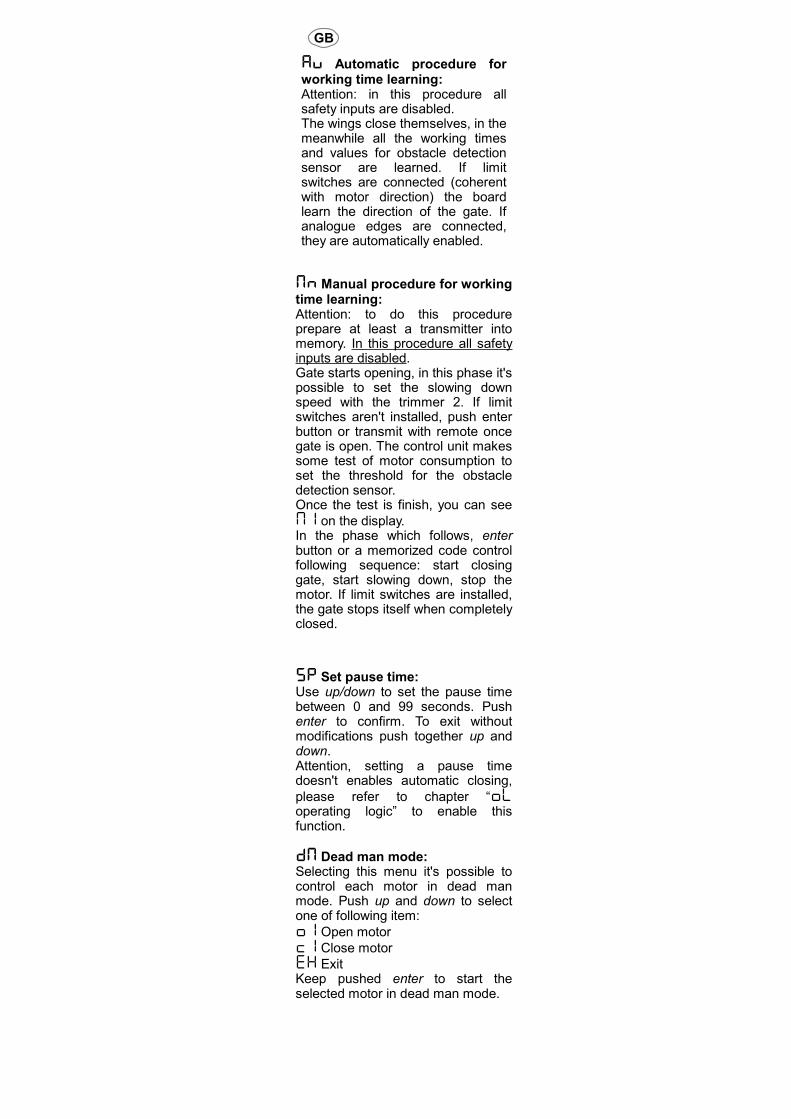
AU Automatic procedure for working time learning:Attention: in this procedure all safety inputs are disabled.The wings close themselves, in the meanwhile all the working times and values for obstacle detection sensor are learned. If limit switches are connected (coherent with motor direction) the board learn the direction of the gate. If analogue edges are connected, they are automatically enabled.
MN Apprendimento tempo di lavoro con procedura manuale:Attenzione: Per eseguire questa procedura è utile avere almeno un trasmettitore memorizzato. In questa fase le sicurezze non sono attive.Come prima cosa Il cancello parte aprendo, in questa fase l'operatore può agire sul trimmer 2 per regolare a proprio piacimento la velocità di rallentamento. Se non sono installati i finecorsa, quando il cancello è completamente aperto, premere nuovamente il tasto enter oppure trasmettere un telecomando memorizzato. In questa fase la centrale esegue una serie di test di consumo del motore, per stabilire la soglia di rilevazione ostacolo, Quando il
test è completato sul display appare M1.Nella fase che segue il tasto enter od un codice radiocomando memorizzato determinano in sequenza la partenza del motore in chiusura, l'inizio del rallentamento, e l'arresto. Se sono installati i finecorsa il motore si ferma da solo a completa chiusura.
MN Manual procedure for working time learning:Attention: to do this procedure prepare at least a transmitter into memory. In this procedure all safety inputs are disabled.Gate starts opening, in this phase it's possible to set the slowing down speed with the trimmer 2. If limit switches aren't installed, push enter button or transmit with remote once gate is open. The control unit makes some test of motor consumption to set the threshold for the obstacle detection sensor.Once the test is finish, you can see
M1 on the display.In the phase which follows, enter button or a memorized code control following sequence: start closing gate, start slowing down, stop the motor. If limit switches are installed, the gate stops itself when completely closed.
5P Imposta tempo di pausa:Usare freccia su/giù per impostare il tempo di pausa tra 0 e 99 secondi. Premere enter per confermare. Per uscire senza apportare modifiche premere freccia su/giù contemporaneamente. Attenzione, impostando un tempo di pausa non si abilita automaticamente la chiusura automatica, fare riferimento al paragrafo
“OL logica di funzionamento “ per abilitare questa funzione.
DM Modalità uomo presente:Questo menu permette di controllare ciascun motore in modo uomo presente.Premendo freccia su e freccia giù si seleziona una delle seguenti voci:
O1 Apri motore
C1 Chiudi motore
EX EsciPremere e tenere premuto enter per azionare il motore in modo uomo presente.
5P Set pause time:Use up/down to set the pause time between 0 and 99 seconds. Push enter to confirm. To exit without modifications push together up and down.Attention, setting a pause time doesn't enables automatic closing,
please refer to chapter “OL operating logic” to enable this function.
DM Dead man mode:Selecting this menu it's possible to control each motor in dead man mode. Push up and down to select one of following item:
O1 Open motor
C1 Close motor
EX ExitKeep pushed enter to start the selected motor in dead man mode.
I GB F
11
Programmazione della schedaMenu avanzato:Per accedere al menu avanzato, tenere premuto il tasto enter fino a quando non
compare sul display la scritta TM. Con le freccie su/giù è possibile selezionare le altre voci di questo menu. Per uscire dal menu selezionare esci
(EX) oppure premere freccia su e freccia giù contemporaneamente. Trascorso un tempo di 2 minuti senza nessuna azione, la centrale esce autonomamente da questo menu.
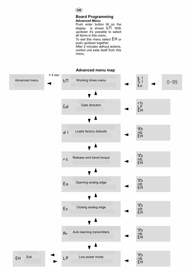
Board Programming Advanced MenuPush enter button till on the
display is shown TM. With up/down it's possible to select all items in this menu.
To exit this menu select EX or push up/down together.After 2 minutes without actions, control unit exits itself from this menu.
I GB F
Schema menu avanzato Advanced menu map Schème du menu avancé
Menu avanzato Advanced menu
Menu avancé
Menu tempi lavoroWorking times menu
Menu du temps du travailTM
Direzione motoreGate direction
Direction du portail GD
Carica impostazioni di fabbricaLoads factory defaults
Charge valeur de fabriqued1
≈ 4 sec.
Inversione a fine corsaRelease end travel torqueInversion a fin de course
RC
EsciExit
SortieEX
T151TC
RHLfEX
YSNTEX
YSNTEX
Costa analogica aperturaOpening analog edge
Cote analogique de ouvertureEO
YSNTEX
Costa analogica chiusuraClosing analog edge
Cote analogique de fermetureEc
YSNTEX
0-99
Apprendimento codici a distanzaAuto learning transmitters
Apprentissage automatique TxAR
YSNTEX
Modo basso consumoLow power mode
Mode faible consommationLP
YSNTEX

I GB F
Menu avanzatoTM Menu tempi di lavoro:In questo menu è possibile modificare i seguenti tempi di lavoro della centrale:
T1 – Tempo lavoro motore
51 – Tempo inizio rallentamento motore
TC – Tempo Luce di cortesia (in decine di secondi)
EX – esce dal menu avanzatoUna volta selezionato il tempo di lavoro da cambiare, usare freccia su/giù per modificarlo da 0 a 99 secondi. Premere enter per confermare. Per uscire senza apportare modifiche selezionare EH o premere freccia su/giù contemporaneamente.
Advanced menuTM Working times menu:In this menu it's possible to modify working times of control unit:
T1 – Working time motor 1
51 – Start time slowdown motor 1
TC – Courtesy light time (x10 sec)
EX – Exits from advanced menu Once selected working time to be changed, use up/down to modify it from 0 to 99 seconds. Push enter to confirm.To exit without modifications select
EH or push together up and down.
GD Direzione motore:In questo menu è possibile invertire senso di marcia e posizione dei finecorsa, a seconda che il cancello sia destro o sinistro.
su/giù per Scegliere tra destro (RX),
sinistro (LF), esci (EX). Premere enter per confermare.
GD Gate direction:In this menu it's possible to invert motor direction and limit switches according if gate is right or left. Use up/down to choose right
(RH), left (LF) or exit (EX). Push enter to confirm.
D1 Carica impostazioni di default:Scegliendo questo menu e confermando
con si (Y5), si riporta la scheda alle condizioni di fabbrica.
D1 Load defaults:Choosing this menu and
confirming with yes (Y5), sets the control unit at factory defaults.
RC Inversione a fine corsa:Abilitando questa funzione si aggiunge un piccolo colpo d'inversione a finecorsa, in modo da allentare la tensione meccanica dei motori. Questa funzione è attiva solo se non sono installati i finecorsa. Usare
freccia su/giù per Scegliere tra si (Y5), no
(NT), esci (EX). Premere enter per confermare.
RC Release torque at work end:Enabling this function, the motors reverse direction for a while to release the torque at end of work. This function is enabled just if limit switches aren't installed. Use
up/down to choose yes (Y5), not
(NT) or exit (EX). Push enter to confirm.
EO Abilitazione costa analogica di apertura:In questo menu si abilita la costa analogica 8K2 relativa all'apertura.
EO Enable opening analogue edge:Enabling this function it's enabled the edge active in opening period.
EC Abilitazione costa analogica di chiusura:In questo menu si abilita la costa analogica 8K2 relativa alla chiusura.
AT Abilitazione apprendimento codici a distanza:Quando questa funzione è attiva, è possibile inserire nuovi codici senza accedere al menu di programmazione. Fare riferimento al paragrafo “Autoapprendimento trasmettitori”.
LP Abilitazione modo basso consumo:In questo menu si abilita il risparmio energetico della scheda. Attenzione: Quando questa funzione è attiva, il display non mostra più lo stato degli ingressi (Display spento in attesa di comandi).
EO Enable closing analogue edge:Enabling this function it's enabled the edge active in closing period.
At Enable automatic transmitters leaning:Enabling this function it's possible to insert new transmitters without accessing base menu. Refer to “Automatic transmitters learning”.
LP Enable low power mode:In this menu you can enable the low power mode. Attention: when this function is enabled, the display is not longer showing input status (Display off in stand-by).

Tabelle logica funzionamento
5T Passo - passo
Operating logic tables
5T Step by step
Table de logique de fonctionnement5T Pas- Pas
I GB F
Fase Comando
Start PedonalePedestrianPiéton
FotocellulaPhotocellPhotocellule
FotostopPhotostopPhotostop
Costa apriEdge openingBord Ouverture
Costa chiudiEdge closingBord fermeture
Stop
ChiusoClosedFerme
ApreOpensOuvre
ApreOpensOuvre
IgnoratoIgnoredIgnore
BloccaStopsArrête
BloccaStopsArrête
IgnoratoIgnoredIgnore
Stop
In aperturaOpeningEn ouverture
FermaStopsArrête
FermaStopsArrête
IgnoratoIgnoredIgnore
Ferma e attende rilascioStops and waits releaseArrête et attendre relâche
Inverte 1 sec.ReversesInverse
IgnoratoIgnoredIgnore
ApertoOpenOuverte
ChiudeClosesFerme
ChiudeClosesFerme
IgnoratoIgnoredIgnore
BloccaStopsArrête
IgnoratoIgnoredIgnore
BloccaStopsArrête
In chiusuraClosingEn fermeture
FermaStopsArrête
FermaStopsArrête
InverteReversesInverse
InverteReversesInverse
IgnoratoIgnoredIgnore
InverteReversesInverse
AT Chiusura automatica AT Automatic closing AT Fermeture automatique
I GB F
Fase Comando
Start PedonalePedestrianPiéton
FotocellulaPhotocellPhotocellule
FotostopPhotostopPhotostop
Costa apriEdge openingBord Ouverture
Costa chiudiEdge closingBord fermeture
Stop
ChiusoClosedFerme
ApreOpensOuvre
ApreOpensOuvre
IgnoratoIgnoredIgnore
BloccaStopsArrête
BloccaStopsArrête
IgnoratoIgnoredIgnore
Stop
In aperturaOpeningEn ouverture
FermaStopsArrête
FermaStopsArrête
IgnoratoIgnoredIgnore
Ferma e attende rilascioStops and waits releaseArrête et attendre relâche
Inverte 1 sec.ReversesInverse
IgnoratoIgnoredIgnore
ApertoOpenOuverte
ChiudeClosesFerme
ChiudeClosesFerme
BloccaStopsArrête
BloccaStopsArrête
IgnoratoIgnoredIgnore
BloccaStopsArrête
In pausaDuring pauseEn pause
Esci pausaExits pauseSortie pause
Esci pausaExits pauseSortie pause
Ricarica tempoReloads timeRecharge temp
Ricarica tempoReloads timeRecharge temp
IgnoratoIgnoredIgnore
Ricarica tempoReloads timeRecharge temp
In chiusuraClosingEn fermeture
FermaStopsArrête
FermaStopsArrête
InverteReversesInverse
InverteReversesInverse
IgnoratoIgnoredIgnore
InverteReversesInverse
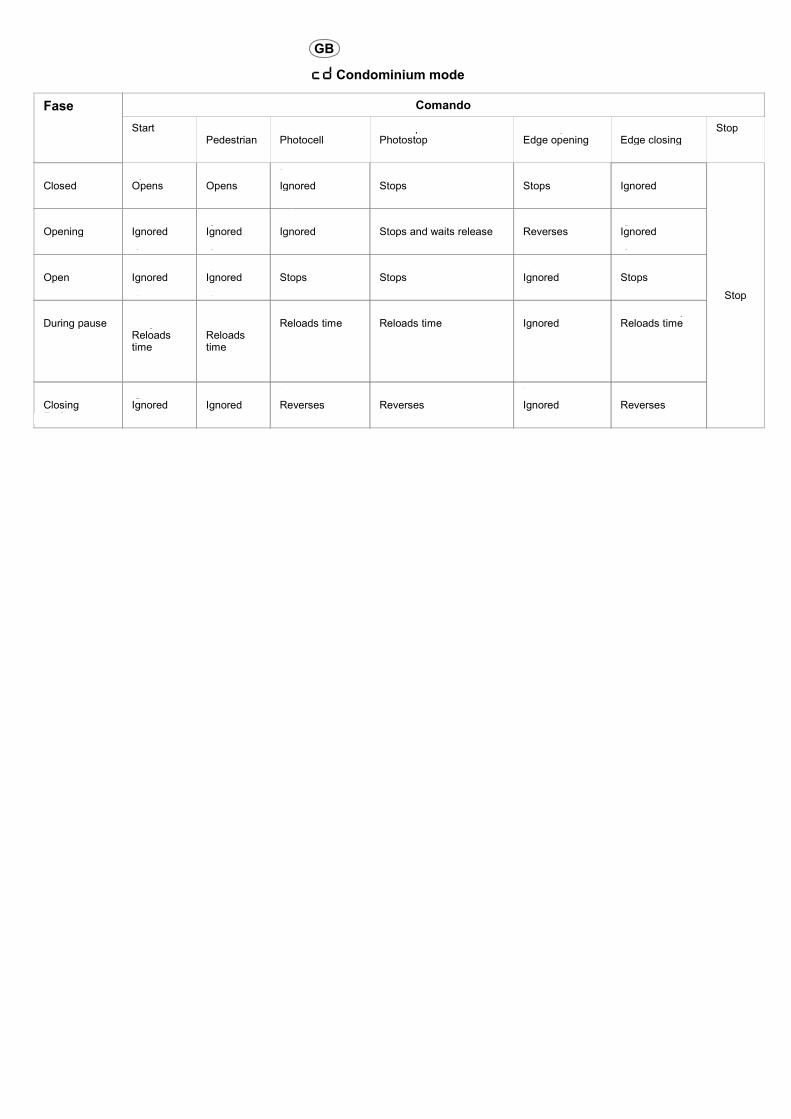
CD Condominiale CD Condominium mode CD Modalité collective
I GB F
Fase Comando
Start PedonalePedestrianPiéton
FotocellulaPhotocellPhotocellule
FotostopPhotostopPhotostop
Costa apriEdge openingBord Ouverture
Costa chiudiEdge closingBord fermeture
Stop
ChiusoClosedFerme
ApreOpensOuvre
ApreOpensOuvre
IgnoratoIgnoredIgnore
BloccaStopsArrête
BloccaStopsArrête
IgnoratoIgnoredIgnore
Stop
In aperturaOpeningEn ouverture
IgnoratoIgnoredIgnore
IgnoratoIgnoredIgnore
IgnoratoIgnoredIgnore
Ferma e attende rilascioStops and waits releaseArrête et attendre relâche
Inverte 1 sec.ReversesInverse
IgnoratoIgnoredIgnore
ApertoOpenOuverte
IgnoratoIgnoredIgnore
IgnoratoIgnoredIgnore
BloccaStopsArrête
BloccaStopsArrête
IgnoratoIgnoredIgnore
BloccaStopsArrête
In pausaDuring pauseEn pause
Ricarica tempoReloads timeRecharge temp
Ricarica tempoReloads timeRecharge temp
Ricarica tempoReloads timeRecharge temp
Ricarica tempoReloads timeRecharge temp
IgnoratoIgnoredIgnore
Ricarica tempoReloads timeRecharge temp
In chiusuraClosingEn fermeture
IgnoratoIgnoredIgnore
IgnoratoIgnoredIgnore
InverteReversesInverse
InverteReversesInverse
IgnoratoIgnoredIgnore
InverteReversesInverse
Programmazione di fabbricaSegue lista delle impostazioni di fabbrica, le stesse che vengono impostate successivamente al comando
D1 del menu avanzato.
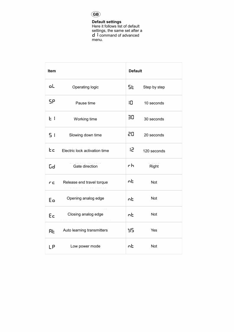
Default settingsHere it follows list of default settings, the same set after a
D1 command of advanced menu.
Programmation de default
I GB F
ParametroItemParametrè
Default
Logica di funzionamentoOperating logic
Logique de fonctionnement
Passo – PassoStep by step
Pas - Pas
Tempo di pausaPause time
Tempe de pause
10 secondi10 seconds
Tempo di lavoroWorking time
Tempe du travail
30 secondi30 seconds
Tempo inizio rallentamentoSlowing down time
Tempe de ralentissement
20 secondi20 seconds
Tempo luce cortesiaElectric lock activation timeTempe de activation serrure
120 secondi120 seconds
Direzione cancelloGate direction
Direction du portail
DestraRightDroit
Inversione a fine corsaRelease end travel torqueInversion a fin de course
NoNot
Costa analogica aperturaOpening analog edge
Cote analogique de ouverture
NoNot
Costa analogica chiusuraClosing analog edge
Cote analogique de fermeture
NoNot
Apprendimento codici a distanzaAuto learning transmitters
Apprentissage automatique Tx
SiYes
Modo basso consumoLow power mode
Mode faible consommation
NoNot
OL 5T
5P 10
T1 30
51 20
TC 12
GD RH
RC NT
EO NT
EC NT
AT Y5
LP NT

Diagnostica e risoluzione problemiLa centrale è in grado di eseguire un autodiagnosi continua e di rivelare problemi. Qualora si verifichi un problema, questo viene segnalato sul display alternato allo stato ingressi.Segue tabella errori con le possibili cause/soluzioni.
Diagnostic and troubleshootingThe control unit has a self diagnostic software able to find problems. Once a problem occurs, a code is shown on the display in alternance with command status.Here it follows a troubleshooting table.
Diagnostique et résolution des problèmes
I GB F
Codice erroreError codeCode d'erreur
Problema ed eventuale soluzioneProblem and eventual solutionProblème et solution éventuelle
E1
Manca la tensione di rete ed il sistema sta lavorando con la batteria tampone.Verificare che non sia scattato il contatore o l'interruttore differenziale. Verificare il fusibile sul trasformatore (portafusibile).
Mains power fails, system is running with backup battery. Verify mains switch and life switch. Verify fuse on transformer (fuse holder).
E2
Rilevato ostacolo nella manovra precedente.Controllare che il cancello sia libero e non ci siano ostacoli sulla sua corsa.Verificare che le ante non siano dure o bloccate
Obstacle detected in the previous cycle.Verify that gate is free and there's no obstacles in the range. Verify gate wings aren't blocked.
E3
Fotocellule o fotostop ostruiti da più di 2 minuti. Il cancello non si muove ed il lampeggiante potrebbe essere acceso di luce fissa.Verificare che le fotocellule ed il fotostop non siano ostruiti, che non ci siano insetti negli stessi. Verificare le connessioni a questi dispositivi.
Photocells or photostop obstructed for longer than 2 minutes. The gate can't start moving and the blinker could be fixed on.Verify that photocells and photostop aren't obstructed, and if there's no bugs inside them. Verify wiring to this devices.
E4
Una delle coste analogiche è ingaggiata da più di 2 minuti.Verificare che le coste analogiche siano libere, verificare i collegamenti.Se non ci sono coste installate, disattivarle nel menu avanzato.
One of the analog edge is engaged for longer than 2 minutes.Verify edges aren't engaged, verify wiring to this devices. If no edge installed, disable them in the advanced menu.
e5
Lo stop è ingaggiato da più di due minuti.Verificare i collegamenti al dispositivo di emergenza. Se non ci sono dispositivi di emergenza installati, fare ponte su questo ingresso.
Stop is engaged for longer than 2 minutes.Verify wiring to emergency device. If there isn't an emergency device installed, shunt this input with the common.
E6
Problemi al motore.Verificare il collegamento del motore, verificare che il motore funzioni in modo uomo presente.
Problem on motor.Verify connections to the motor, verify motor can work in dead man mode.

GENERAL SOLAR NOTES
SOLAR PANEL SIZEGenerally speaking simple automatic gate installations will work perfectly in Australia using a 10 watt solar panel. The solar panel sizedetermines the amount of energy you can collect each day. In a simple gate installation we need to collect enough energy to power ourcontrol board and run the gate and a 10 watt panel will do this. If however the installation is to include keypads, safety beams or otherpower hungry devices it may be necessary to increase the solar panel size. Another example where you may wish to consider upsizingyour solar panel is where you may have a partially shaded area and you need to collect your energy each day in a shorter period of time. Ifyou do decide to increase the size of your solar panel it may be necessary to install a simple regulator to protect your battery. Check withAutomatic Solutions regarding this.
SOLAR PANEL DIRECTIONYour solar panel ideally should be mounted at an angle of 35 degrees and facing north (NB: In Australia).
NORTH
BATTERY SIZEThe battery stores the energy that you collect each day and your system draws on this battery to operate. All batteries have a limit to theirstorage capacity and can therefore only store enough energy to last our system a certain period of time. What happens if we have forexample three days with little or no sunlight, very dark and overcast days? Our battery capacity reduces. The size of the battery willdetermine the number of days we can have as backup or how many days our system can survivewithout charging. In general terms biggeris better.
CABLESCables must be low voltage cables (5mm is good). Length of cables must be kept to a minimum. Ideally the solar panel will be no morethan 10 metres from the battery and the battery will be no more than 5 metres from the motor. Connections must be clean and good quality.
If using a regulator go
solar panel to regulator,
regulator to battery and
then battery to control
board. Do not take the
board to the regulator.


![USTA TrafficAnalysisBriefing V7 0 20150530 FINAL[1] · PDF file1."Executive"Summary" ... In2014thethreemajorGulfcarriers" –"Emirates,"Qatar"Airways"and"Etihad" Airways"–"carried"some"4.3"million"passengers"intoandout"of"the](https://img.pdfslide.net/doc/110x75/5aa125967f8b9a46238b5bf2/usta-trafficanalysisbriefing-v7-0-20150530-final1-in2014thethreemajorgulfcarriers.jpg)