Embed Size (px)
Citation preview

In order to promote public education and public safety, equal justice for all, a better informed citizenry, the rule of law, world trade and world peace, this legal document is hereby made available on a noncommercial basis, as it is the right of all humans to know and speak the laws that govern them.
Federation of Malysia≠ EDICT OF GOVERNMENT ±
ASD 404 (2007) (English): Lighting Of Obstacles


AIRPORT STANDARDS DIRECTIVE 404 [ASD 404] LIGHTING OF OBSTACLES
AIRPORTS STANDARDS DIVISION
DEPARTMENT OF CIVIL AVIATION MALAYSIA

This Airport Standards Directive is published and enforced by the Director General of Civil Aviation Malaysia under the provision of the Section 24o Civil Aviation Act 1969 (Act 3). © Department of Civil Aviation Malaysia 2007 First published July 2007
Printed and distributed by Department of Civil Aviation Malaysia. Level 1 Block Podium B Lot 4G4 Precinct 4, No. 27 Persiaran Perdana, Federal Government Administration Centre 62618 PUTRAJAYA

AMENDMENT RECORD Amendment Number
Amendment Date
Incorporated by
Incorporated on

CONTENTS Page
INTRODUCTION
1
OBJECTIVE
1
LIGHTING OF OBSTACLES
1
OBSTACLE LIGHTS QUALIFICATION FOR USE
2
OBSTACLE LIGHTS CERTIFICATION
2
AUTHORITY
3
TYPES OF OBSTACLE LIGHTS
3
USE OF OBSTACLE LIGHTS
4
LOCATION OF OBSTACLE LIGHTS
6
CHARACTERISTICS OF OBSTACLE LIGHTS
8
APPENDIX A Obstacle Lights specifications
B Obstacle Lights : Qualification requirements
C Application Form [sample]
D Obstacle Lights Certificate [sample]

INTRODUCTION
1. The Civil Aviation Act 1969 has made provisions for the control and the denoting of obstacles to ensure air navigation could be conducted safely.
2. Airport Standards Directive 401 [ASD401] defines objects regarded as obstacles. Where it
is impractical to eliminate an obstacle, it shall be appropriately marked and/or lighted so as to be clearly visible to pilots in all weather and visibility conditions.
3. This Directive outlines the application of provisions under the Act in the form of rules,
instructions and practices pertaining to the lighting of obstacles and to which aerodrome operator, local authority, developer or property owner shall be informed and obliged to comply.
4. This Directive has been written in general terms. Specific advice could be obtained from
the Authority at:
Department of Civil Aviation Airport Standards Division Level 1 Block Podium B 4G4 Precinct 4 No. 27 Persiaran Perdana Federal Government Administration Centre 62618 Putrajaya. Phone: 03-88714000 Fax : 03-88714335
OBJECTIVE
5. This Directive specifies the type, location and characteristics of obstacle lights to be used in indicating the various obstacles defined in ASD401.
6. This Directive also specifies the environmental, design, and photometric requirements for
obstacle lights equipment to which full compliance is mandatory in order to achieve the required qualification for use in Malaysia.
LIGHTING OF OBSTACLE
7. Objects defined as obstacles in ASD 401 shall be lighted.
8. Objects, where a mandatory obstacle marking as required in ASD 403 is omitted, shall be lighted.
9. Obstacles lights may be omitted –
(i) at an aerodrome, when the aerodrome open is only for daytime operations in
Visual Meteorological Conditions [VMC];
(ii) when the obstacle is shielded by another fixed obstacle;
(iii) when a circuit extensively obstructed by immovable objects of terrain, where procedures have been established to ensure safe vertical clearance; and

(iv) when the obstacle is a lighthouse and an aeronautical study indicates the
lighthouse light to be sufficient.
10. Obstacle lights shall not be installed, on –
(i) elevated aeronautical ground lights and signs in the movement area at aerodromes; and
(ii) aircraft.
11. Obstacle lights may be exempted for aircraft servicing equipment and vehicles used only
on aprons.
QUALIFICATIONS FOR USE
12. Obstacle lights intended to be used for denoting of obstacles in Malaysia shall obtain certification from the Authority.
13. Obstacle lights shall meet full compliance with –
(i) obstacle lights characteristics as in Appendix A of this Directive; and (ii) obstacle lights qualification requirements as in Appendix B of this Directive.
14. The Authority may demand evidence of certification before any proposed obstacle lights
is approved for installation.
OBSTACLE LIGHTS CERTIFICATION
15. Application for the certification of obstacle lights to be used for denoting of obstacles shall be made to the Authority at the following address:
Department of Civil Aviation Airport Standards Division Level 1 Block Podium B 4G4 Precinct 4 No. 27 Persiaran Perdana Federal Government Administration Centre 62618 Putrajaya. Phone: 03-88714000 Fax : 03-88714335
16. The applicant shall submit completed Application Form ASD404/Cert/APL1 and other
documentation as detailed in the application form, as in Appendix C of this Directive. 17. The Authority may require other documentation to facilitate the assessment of
application.
18. The interval between application and assessment by the Authority may depend upon matters within the control of the applicant and no undertaking can be given that the Authority will be able to reach a decision within a particular time period.
19. Based on the assessment of the application the Authority will notify the applicant
whether the application was successful or unsuccessful.
20. If the application was successful, a certificate shall be issued to the Applicant as in Appendix D of this Directive.
AUTHORITY
21. The Authority for certification of obstacle lights is the Department of Civil Aviation Malaysia.
TYPES OF OBSTACLE LIGHTS
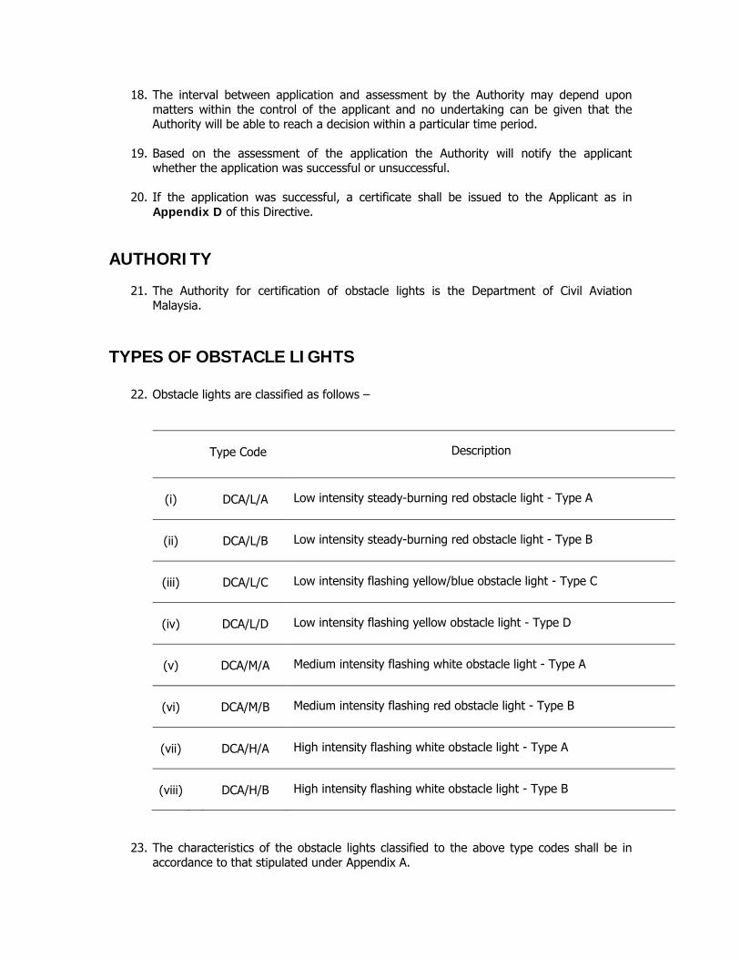
22. Obstacle lights are classified as follows –
Type Code
Description
(i) DCA/L/A
Low intensity steady-burning red obstacle light - Type A
(ii) DCA/L/B
Low intensity steady-burning red obstacle light - Type B
(iii) DCA/L/C
Low intensity flashing yellow/blue obstacle light - Type C
(iv) DCA/L/D
Low intensity flashing yellow obstacle light - Type D
(v) DCA/M/A
Medium intensity flashing white obstacle light - Type A
(vi) DCA/M/B
Medium intensity flashing red obstacle light - Type B
(vii) DCA/H/A
High intensity flashing white obstacle light - Type A
(viii) DCA/H/B
High intensity flashing white obstacle light - Type B
23. The characteristics of the obstacle lights classified to the above type codes shall be in accordance to that stipulated under Appendix A.

USE OF OBSTACLE LIGHTS
24. The presence of objects defined as obstacles shall be indicated by Low-intensity [L], Medium-intensity [M] or High-intensity [H] obstacle lights, or a combination of such lights.
25. The application of the various type codes of obstacle lights is determined by conditions
detailed in the following paragraphs. LOW-INTENSITY OBSTACLE LIGHTS
26. DCA/L/A or DCA/L/B shall be used where the objects are -
a. less extensive; and
b. height above surrounding ground is less than 45 metres.
Note: A group of trees or buildings is regarded as an extensive object.
27. DCA/L/A is only applicable for the lighting of obstacles at aerodromes.
28. Where DCA/L/A and DCA/L/B would be inadequate or an early special warning is required than Medium-intensity obstacle lights or High-intensity obstacle lights should be used.
29. DCA/L/C shall be displayed on vehicles and other mobile objects, at an aerodrome,
excluding aircraft. 30. DCA/L/D shall be displayed on follow-me vehicles.
MEDIUM-INTENSITY OBSTACLE LIGHTS
31. DCA/M/A and/or DCA/M/B shall be used where the objects are -
a. extensive; and
b. height above surrounding ground is greater than 45 metres but less than 150 metres.
HIGH-INTENSITY OBSTACLE LIGHTS
32. DCA/H/A shall be used where the objects are -
a. height above surrounding ground is greater than 150 metres; and
b. an aeronautical study indicated such lights are essential for the recognition of the object by day.

33. DCA/H/B should be used to indicate the presence of tower supporting overhead wires and cables where -
a. such lights is essential for the recognition of the presence of the tower, wires
and cables; or
b. where markers on wires and cables are omitted. COMBINE OBSTACLE LIGHTS
34. Where, in the opinion of the Authority, that the use of –
a. DCA/H/A;
b. DCA/H/B; or
c. DCA/M/A - in the vicinity of an aerodrome [within approximately 10000 metres radius], may dazzle
pilots or cause significant environmental concerns, a dual obstacle lighting system shall be provided.
35. A dual obstacle lighting system shall be composed of –
a. DCA/H/A or DCA/H/B or DCA/M/A as appropriate for daytime and twilight use;
with
b. DCA/M/B for night-time use.
36. DCA/M/B may be combined with DCA/L/B. OMISSION OF MARKINGS
37. DCA/M/A shall be used, by day, where markings are omitted for fixed obstacle with height that does not exceed 150 metres of surrounding ground, and located -
a. within 3000 metres of the inner edge of the Take-off Climb Surface;
b. within 3000 metres of the inner edge of the Approach Surface; or
c. above the Horizontal Surface
38. DCA/L/A or DCA/L/B shall be used, by day, Where markings are omitted for fixed
obstacle with height that exceed 150 metres of surrounding ground, and located -
a. within 3000 metres of the inner edge of the Take-off Climb Surface;
b. within 3000 metres of the inner edge of the Approach Surface; or
c. above the Horizontal Surface
LOCATION OF OBSTACLE LIGHTS
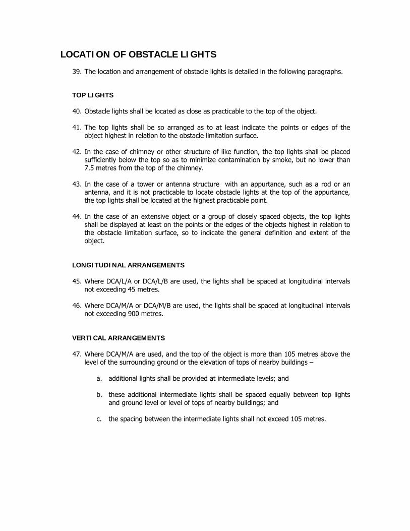
39. The location and arrangement of obstacle lights is detailed in the following paragraphs. TOP LIGHTS
40. Obstacle lights shall be located as close as practicable to the top of the object.
41. The top lights shall be so arranged as to at least indicate the points or edges of the object highest in relation to the obstacle limitation surface.
42. In the case of chimney or other structure of like function, the top lights shall be placed
sufficiently below the top so as to minimize contamination by smoke, but no lower than 7.5 metres from the top of the chimney.
43. In the case of a tower or antenna structure with an appurtance, such as a rod or an
antenna, and it is not practicable to locate obstacle lights at the top of the appurtance, the top lights shall be located at the highest practicable point.
44. In the case of an extensive object or a group of closely spaced objects, the top lights
shall be displayed at least on the points or the edges of the objects highest in relation to the obstacle limitation surface, so to indicate the general definition and extent of the object.
LONGITUDINAL ARRANGEMENTS
45. Where DCA/L/A or DCA/L/B are used, the lights shall be spaced at longitudinal intervals not exceeding 45 metres.
46. Where DCA/M/A or DCA/M/B are used, the lights shall be spaced at longitudinal intervals
not exceeding 900 metres. VERTICAL ARRANGEMENTS
47. Where DCA/M/A are used, and the top of the object is more than 105 metres above the level of the surrounding ground or the elevation of tops of nearby buildings –
a. additional lights shall be provided at intermediate levels; and b. these additional intermediate lights shall be spaced equally between top lights
and ground level or level of tops of nearby buildings; and
c. the spacing between the intermediate lights shall not exceed 105 metres.

48. Where DCA/M/B are used, and the top of the object is more than 45 metres above the level of the surrounding ground or the elevation of tops of nearby buildings –
a. additional lights shall be provided at intermediate levels; and b. these additional intermediate lights shall be alternately DCA/L/B and DCA/M/B;
and
c. the DCA/L/B and DCA/M/B lights shall be spaced equally between top lights and ground level or level of tops of nearby buildings; and
d. the spacing between the intermediate lights shall not exceed 52 metres.
49. Where DCA/H/A are used, and the top of the object is more than 105 metres above the level of the surrounding ground or the elevation of tops of nearby buildings –
a. additional lights shall be provided at intermediate levels; and b. these additional intermediate lights shall be spaced equally, between top lights
and ground level or level of tops of nearby buildings; and
c. the spacing between the intermediate lights shall not exceed 105 metres.
50. Where DCA/H/B are used they shall be located at three levels
a. at the top of the tower; b. at the lowest level of the catenary of wires or cables; and
c. approximately midway between these two levels.
AZIMUTH ARRANGEMENTS
51. The installation setting angles for DCA/H/A and DCA/H/B should be in accordance with the following –
Height of light unit
above terrain
Angle of the peak of the beam above the horizontal
Greater than 151 m. AGL 0º 122 m. to 151 m. AGL 1º 92 m. to 122m. AGL 2º Less than 92 m. AGL 3º
52. The number and arrangement of obstacle lights at each level shall be such that the
object is indicated from every angle in azimuth.
53. Where a light is shielded in any direction by another part of the object, or by an adjacent object, additional lights shall be provided on the object in such a way as to retain the general definition of the object to be lighted. If the shielded light does not contribute to the definition of the object, it may be omitted.

CHARACTERISTICS OF OBSTACLE LIGHTS
54. Obstacle lights characteristics shall be in accordance with that in the Appendix A of this Directive.
LOW-INTENSITY OBSTACLE LIGHTS
55. DCA/L/A and DCA/L/B located on fixed objects shall be fixed [steady-burning] red lights.
56. DCA/L/C displayed on emergency or security vehicles shall be flashing-blue and on other vehicles shall be flashing-yellow.
57. DCA/L/D displayed on follow-me vehicles shall be flashing-yellow.
58. DCA/L/A should be used for objects with limited mobility at aerodromes.
MEDIUM-INTENSITY OBSTACLE LIGHTS
59. DCA/M/A shall be flashing-white lights and DCA/M/B shall be flashing-red lights.
60. DCA/M/A and DCA/M/B located on an object shall flash simultaneously. HIGH-INTENSITY OBSTACLE LIGHTS
61. DCA/H/A and DCA/H/B shall be flashing-white lights.
62. DCA/H/A located on an object shall flash simultaneously.
63. DCA/H/B shall flash sequentially; first the middle light, second the top light and last the bottom light.
64. The interval between flashes should approximate the following ratios -
Flash interval between
Ratio of cycle time
middle and top light 1/13 top and bottom light 2/13
bottom and middle light 10/13
65. The Appendices to this Directive shall be taken, construed, read and be part of this
Directive. AZHARUDDIN ABDUL RAHMAN Director General Department of Civil Aviation Malaysia Dated: 16 JULY 2007

APPENDIX B OBSTACLE LIGHTS : QUALIFICATION REQUIREMENTS 1. GENERAL
1.1 This Appendix addresses the environmental, design, and photometric requirements
for obstacle lights equipment to which full compliance is mandatory in order to achieve the required qualification for use in Malaysia.
1.2 Evidence of compliance with qualification requirements including qualifying test and
test results shall be furnished to the Authority for the purpose of certification as required in this Directive.
2. ENVIRONMENTAL REQUIREMENTS
2.1 Obstacle lights equipment shall be designed for continuous operation under the following conditions –
i. Temperature : 0º C to +70ºC
ii. Humidity : 95% relative humidity
iii. Wind : Wind speeds up to 150 km/h
iv. Wind-blown rain : Exposure to wind-blown rain from any direction [IP65]
v. Salt Fog : Exposure to salt-laden atmosphere
3. DESIGN REQUIREMENTS
3.1 Light Unit
3.1.1 The light unit shall be light-weight and designed for easy servicing and lamp [or flashtube] replacement.
3.1.2 Materials used within the light unit shall be selected for compatibility with
their environment. 3.1.3 Each light unit shall be an independent unit and shall operate at the specified
intensity or at its highest intensity when control signals are absent.
3.1.4 Obstacle lights Types DCA/L/A, DCA/L/B and DCA/M/B shall be the Light Emitting Diode [LED] type and shall be maintenance free. The rated light life shall be more than 50,000 hours without loss of light output below the minimum specified candela as indicated in the specifications in Appendix A.

3.2 Light Covers
3.2.1 Light transmitting covers for light units shall conform to the requirements of MIL-C-7989.
3.3 Light Colours
3.3.1 Red obstacle lights
The aviation red shall be in accordance with ICAO Annex 14 Volume 1 Appendix 1 Fig. A1-1 colours for aeronautical ground lights at operating temperature within the following chromaticity boundaries:
purple boundary
y = 0.980 – x
yellow boundary
y = 0.335
3.3.2 White obstacle lights Xenon flashtube emission is acceptable.
3.4 Aiming
3.4.1 Obstacle Lights Types DCA/H/A and DCA/H/B shall have a method for
adjustment of the vertical aiming angle between 0 and +8º. A spirit level or other device shall be provided as part of each light unit for setting the vertical aiming angle of the light beam with an accuracy of 1º.
3.5 Control Unit
3.5.1 Flashing White Obstacle Lights System DCA/M/A, DCA/H/A and DCA/H/B
3.5.1.1 Control
(i) The control unit shall set the system's flash rate, intensity and
sequence. (ii) The control unit shall be capable of controlling light units up to a
distance of 760 meters. (iii) If the control unit or control wiring fails, the light units shall
continue to flash in accordance with specified flash rate. (iv) Failure of an intensity step change circuit shall cause all light units
to remain operating at their proper intensity or alternatively to operate at the high intensity step.

3.5.1.2 Monitoring
(i) Each light unit shall be monitored for FLASH/FAIL status. (ii) FAIL status is defined as either of the following conditions –
(a) unit misses four or more consecutive flashes (b) unit flashes at wrong intensity step during day operation
(iii) Monitoring shall be fail-safe that is the presence of active signals for FLASH in the absence of signals for FAIL.
(iv) There shall be provisions to permit connection to a remote alarm
device, to indicate system and individual light unit FLASH/FAIL status.
3.5.1.3 Placement and Remote Monitoring
(i) The control unit may be consolidated in a light unit (ii) The monitoring unit shall be in a single enclosure for remote
mounting at an easily accessible place for continuous monitoring purpose and may be connected to monitor several light units.
(iii) If the control unit is consolidated in the monitoring unit they may
be distributed into several lights.
(iv) The monitoring unit shall display the status of each light unit.
(v) An intensity control override switch shall also be mounted in the enclosure to manually control light intensity during maintenance or in the event of a photoelectric control malfunction.
3.5.2 Flashing Red Obstacle Lights System DCA/M/B
3.5.2.1 Control
(i) The control unit shall set the system flash rate, simulated flash rate and flash sequence.
(ii) Failure of the flashing circuit or rotation motor shall cause the
light units to come "on" steady-burning.
(iii) An override switch shall be mounted on the control unit to manually control the lights during maintenance or in the event of a lack of a photoelectric control signal.
(iv) To ensure correct operations, all flashing or rotational red obstacle
lights including the fail-safe steady-burning system and associated

control unit [whether consolidated or externally mounted types] shall be tested and certified accredited laboratory.
3.5.2.2 Monitoring
(i) Each light unit shall be monitored for FLASH/FAIL status. (ii) FAIL status is defined as either of the following conditions –
(a) unit misses four or more consecutive flashes (b) unit flashes at wrong intensity step during day operation.
(iii) Monitoring shall be fail-safe that is the presence of active signals for FLASH in the absence of signals for FAIL.
(iv) There shall be provisions to permit connection to a remote alarm
device, to indicate system and individual light unit FLASH/FAIL status.
3.5.2.3 Placement and Remote Monitoring
(i) The control unit may be consolidated in a light unit (ii) The monitoring unit shall be in a single enclosure for remote
mounting at an easily accessible place for continuous monitoring purpose and may be connected to monitor several light units.
(iii) If the control unit is consolidated in the monitoring unit they may
be distributed into several lights.
(iv) The monitoring unit shall display the status of each light unit.
(v) An intensity control override switch shall also be mounted in the enclosure to manually control light intensity during maintenance or in the event of a photoelectric control malfunction.
3.5.3 Dual Lighting System
DCA/H/A, DCA/H/B or DCA/M/A with DCA/M/B
3.5.3.1 Control
(i) The control unit may be a separate unit or incorporated as part of either the white or red obstacle light control unit.
(ii) The control unit shall set the operating mode for each light unit in
the system.
(iii) Outage of one of two lamps in the uppermost red beacon or outage of any uppermost red strobe shall cause the white obstacle lights to operate in its specified “night” step intensity.
(iv) At no time should both red and white systems be on simultaneously.

(v) An override switch shall be mounted on the control unit to
manually control the operating mode of the system during maintenance or in the event of a lack of photoelectric control signal.
3.5.3.2 Monitoring
(i) Each separate daytime light units and each tier of night light units DCA/M/B light unit shall be monitored for FLASH/FAIL status.
(ii) FAIL status is defined as –
(a) an outage of any lamp in a daytime light unit; (b) outage of any one lamp in a tier of night-time DCA/M/B light
units; or
(c) failure of a flasher or the rotation motor for the DCA/M/B light unit.
(iii) Monitoring shall be fail-safe, with the presence of active signal for
FLASH in the absence of signals for FAIL. (iv) There should be provisions to permit connection to a remote alarm
device, to indicate system and individual light unit FLASH/FAIL status.
3.6 Input Voltage
3.6.1 The obstacle lighting equipment shall be designed to operate from specified
input voltage ± 10 %. 3.6.2 Incandescent type lamps shall be operated to within 3 % of the rated lamp
voltage to provide proper light output.
3.7 Lightning Surge Protection
3.7.1 The power input, control and monitor interface circuitry, where provided, shall be protected by separate surge protection devices [SPD] at the cable entry point of the light units, control units and monitoring interface circuits.
3.7.2 The SPD shall have been tested against defined waveforms detailed in
ANSI/IEEE C62.41-1991, namely, 3,000 Amp 8/20µs [short circuit current pulse] and 6,000 volt 1.2/50µs [open circuit voltage pulse].
3.7.3 The let through voltage of the SPD shall be less than 2 times of the rated
maximum Input voltage of the protected circuitry of the obstruction light equipment.
3.7.4 The surge protection capacity of the separate surge protection devices shall
meet the ANSI/IEEE C62.41-1991 Category C requirement.

3.8 Warning Labels
3.8.1 All enclosures which contain voltages, exceeding 150 volts dc or ac (rms)
shall have high voltage warning label(s) placed at a conspicuous location(s). 3.8.2 A visual indicator shall also be included within the enclosure to indicate that
greater than 150 vdc is present on the high voltage capacitors.
3.9 Interlock switches
3.9.1 Interlock switches required for DCA/H/A, DCA/H/B and DCA/M/A light units. 3.9.2 Interlock switches shall be incorporated in each power supply and optionally
in each flash head so that opening either unit shall –
(i) interrupt incoming power, and (ii) discharge all high voltage capacitors within that enclosure to 50 volts
or less within 30 seconds.
3.10 Nameplate
3.10.1 A nameplate, with the following information, shall be permanently attached to each unit:
(i) Name of unit [light unit, control unit, etc,]
(ii) Obstacle light type reference [DCA/H/A, DCA/M/B, etc]
(iii) Manufacturer’s catalogue number
(iv) Manufacturer’s name and address
(v) Rated separation distance in feet is ……..to……….between power
supply and optical head. [This item is only required if a unique power supply and its associated optical head are separate components of the lighting system as in the case of some discharge lights].
3.10.2 In addition to the above, the power supply shall include nominal input
voltage, number of phases, frequency, and peak voltage-ampere rating (VA) rating.

3.11 Component Ratings
3.11.1 Discharge Lighting Equipment
(i) All components in discharge lighting equipment except the flashtube shall be designed for ease of servicing and to meet performance requirements for a minimum of 1 year without maintenance.
(ii) Flashtube(s) shall have a minimum rated life of 2 years without
maintenance or loss of light output below minimum specified candela.
3.11.2 Component Separation Rating
(i) If the light unit's power supply and optical head are separate components, the manufacturer shall rate each light unit for maximum and minimum separation at a given AWG wire size.
(ii) The manufacturer shall include this rating on the nameplate as required
under paragraph 3.10. (iii) The rating certifies that the unit meets all requirements within the rated
distances. (iv) The manufacturer shall maintain records of test results to support the
stated separation rating.
3.11.3 LED [Light Emitting Diode] Light Equipment
(i) The LED is preferred DCA/L/A, DCA/L/B and DCA/M/B obstacle lights for its inherent long life properties.
(ii) The circuitry of LED light shall be designed to maintain consistent
voltage across LED units to produce consistent light output and ensure long light life.
(iii) LED light shall have a minimum rated life of 50,000 hours.
3.11.4 Leakage Current
(i) All obstacle lighting equipments shall be designed to withstand application of 1000 volts AC or 1414 volts DC between the input power leads and equipment chassis for 10 seconds during which the leakage current shall not exceed 10 micro amperes at ambient room temperature and humidity.

4. PERFORMANCE REQUIREMENTS
4.1 Photometric
4.1.1 General
(i) The effective intensity for flashing lights shall be calculated in accordance with the following formula by the method described for "Flashing Light Signals" in the IES Handbook 1993.
t2 Ie = ∫ Idt / (0.2 + t2 - t1) t1
where Ie = Effective intensity [Candela] I = Instantaneous intensity [Candela]
t1 , t2 = Times in seconds of the beginning and end of that part of the flash when the value of I exceeds Ie. This choice of the times maximizes the value of Ie.
(ii) For discharge flashing lights, the equipment shall provide the specified
light output at the specified temperature extremes as the input voltage simultaneously varies by ±10 percent from nominal.
(iii) The light intensity and beam distribution requirements for obstacle
lighting equipment are specified below.
(iv) All intensities listed are effective intensities [except steady-burning red obstacle lights] measured at the flash rate specified in Appendix A.
(v) All incandescent lights will be tested as steady burning lights.
(vi) The effective intensity for multiple pulse flashes as used in strobe lights
during nighttime operation shall also be calculated.
(vii) The frequency of the pulses shall not be less than 100 Hz and the interval t2- t1 shall not vary by more than ± 5% from the nominal value from pulse to pulse over the simultaneous extremes of temperature and input voltage.
4.1.2 Low Intensity Type DCA/L/B light unit (i) The centre of the vertical beam spread shall lie between +4º and +20º. (ii) With a minimum vertical beam spread of 10º and at all radials
throughout the omni directional 360º there shall be a minimum intensity of 32 candelas.
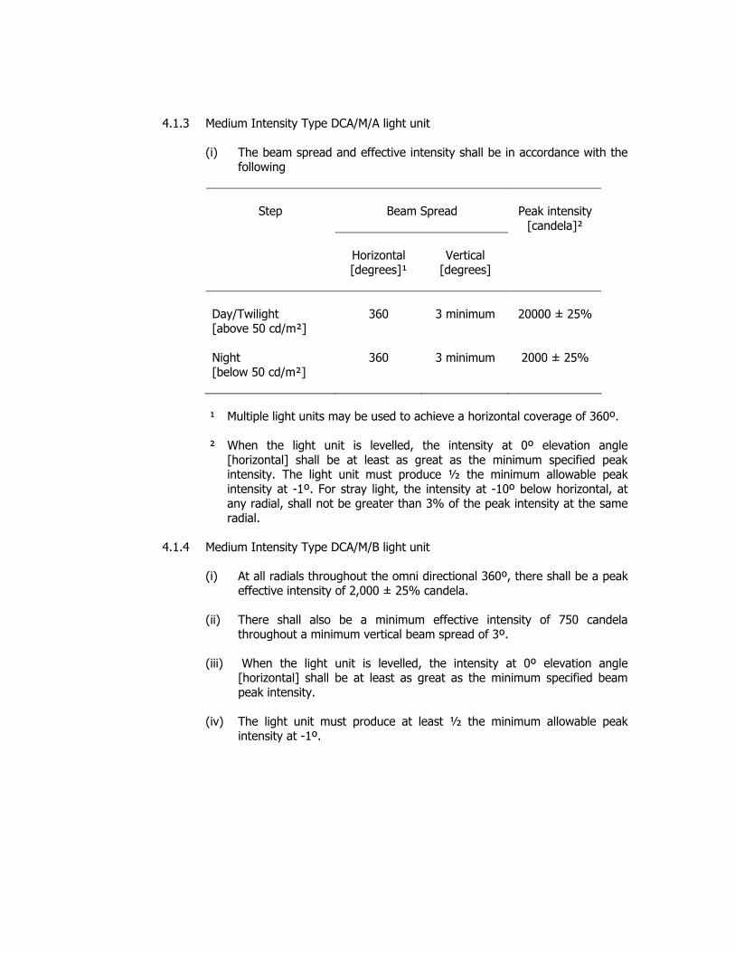
4.1.3 Medium Intensity Type DCA/M/A light unit (i) The beam spread and effective intensity shall be in accordance with the
following
Beam Spread
Step
Horizontal [degrees]¹
Vertical
[degrees]
Peak intensity
[candela]²
Day/Twilight [above 50 cd/m²] Night [below 50 cd/m²]
360
360
3 minimum
3 minimum
20000 ± 25%
2000 ± 25%
¹ Multiple light units may be used to achieve a horizontal coverage of 360º.
² When the light unit is levelled, the intensity at 0º elevation angle
[horizontal] shall be at least as great as the minimum specified peak intensity. The light unit must produce ½ the minimum allowable peak intensity at -1º. For stray light, the intensity at -10º below horizontal, at any radial, shall not be greater than 3% of the peak intensity at the same radial.
4.1.4 Medium Intensity Type DCA/M/B light unit
(i) At all radials throughout the omni directional 360º, there shall be a peak
effective intensity of 2,000 ± 25% candela. (ii) There shall also be a minimum effective intensity of 750 candela
throughout a minimum vertical beam spread of 3º. (iii) When the light unit is levelled, the intensity at 0º elevation angle
[horizontal] shall be at least as great as the minimum specified beam peak intensity.
(iv) The light unit must produce at least ½ the minimum allowable peak
intensity at -1º.

4.1.5 High Intensity Type DCA/H/A light unit
(i) The beam spread and effective intensity shall be in accordance with the following
Beam Spread
Step
Horizontal [degrees]¹
Vertical
[degrees]
Peak intensity
[candela]²
Day [above 500 cd/m²] Twilight [between 50-500 cd/m²] Night [below 50 cd/m²]
90 or 120
90 or 120
90 or 120
3 to 7
3 to 7
3 to 7
200,000 ± 25%
20,000 ± 25%
2,000 ± 25%
¹ Multiple light units may be used to achieve a horizontal coverage of 360º. 2 When the light unit is levelled, the intensity at 0º elevation angle
[horizontal] shall be at least as great as the minimum specified peak intensity. The light unit must produce ½ the minimum allowable peak intensity at -1º. For stray light, the intensity at -10º below horizontal, at any radial, shall not be greater than 3% of the peak intensity at the same radial.

4.1.6 High Intensity Type DCA/H/B light unit
(i) The beam spread and effective intensity shall be in accordance with the following
Beam Spread
Step
Horizontal [degrees]¹
Vertical
[degrees]
Peak intensity
[candela]²
Day [above 500 cd/m²] Twilight [between 50-500 cd/m²] Night [below 50 cd/m²]
90 or 120
90 or 120
90 or 120
3 to 7
3 to 7
3 to 7
100,000 ± 25%
20,000 ± 25%
2,000 ± 25%
¹ Multiple light units may be used to achieve a horizontal coverage of 360º.
² When the light unit is levelled, the intensity at 0º elevation angle
[horizontal] shall be at least as great as the minimum specified peak intensity. The light unit must produce ½ the minimum allowable peak intensity at -1º. For stray light, the intensity at -10º below horizontal, at any radial, shall not be greater than 3% of the peak intensity at the same radial.

4.2 Flash Rate and Duration (i) The flash rate and duration for obstacle lights shall be as indicated –
Type Intensity step Flash rate¹
Flash Duration²
DCA/H/A Day / Twilight 40-60 fpm Less than 10 ms
DCA/H/A Night 40-60 fpm Between 100 and 250 ms
DCA/H/B Day / Twilight 40-60 fpm Less than 10 ms
DCA/H/B Night 40-60 fpm Between 100 and 250 ms
DCA/M/A Day / Twilight 20-60 fpm Less than 10 ms
DCA/M/A Night 20-60 fpm Between 100 and 250 ms
DCA/M/B Single 20-60 fpm Between 100ms to 600ms ¹ Flash rates have a tolerance of ± 5 per cent ² When the effective duration is achieved by a group of short flashes, the short
flashes shall be emitted at a rate of not less than 100 Hz. ³ The light intensity during the ‘off’ period shall be less than 10 per cent of the
peak effective intensity. The `off’ period shall be at least 1/3 of the flash period.
4.3 System Flashing Requirements
4.3.1 Simultaneous Flashing System
(i) All obstacle lights in a system composed of DCA/M/B light units with DCA/H/A and/or DCA/M/A light units shall flash within 1/60 of a second of each other.
4.3.2 Sequenced Flashing Requirements
(i) Catenary support structure system composed of DCA/H/B, DCA/M/A or
DCA/M/B light units shall have sequenced flashing characteristics. (ii) The systems consist of three lighting levels on or near each supporting
structure. One light level is near the top, one at the bottom or lowest point of the catenary, and one midway between the top and bottom.
(iii) The flash sequence shall be middle, top and bottom. (iv) The interval between top and bottom flashes shall be twice the interval
between middle and top flashes.
(v) The interval between the end of one sequence and the beginning of the next shall be about 10 times the interval between middle and top flashes. The time for the completion of one cycle shall be 1 second ± 5 %.
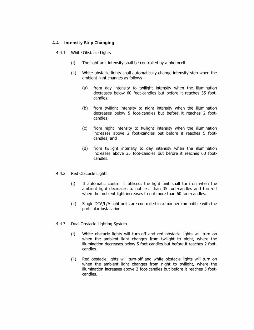
4.4 Intensity Step Changing
4.4.1 White Obstacle Lights (i) The light unit intensity shall be controlled by a photocell. (ii) White obstacle lights shall automatically change intensity step when the
ambient light changes as follows -
(a) from day intensity to twilight intensity when the illumination decreases below 60 foot-candles but before it reaches 35 foot-candles;
(b) from twilight intensity to night intensity when the illumination
decreases below 5 foot-candles but before it reaches 2 foot-candles;
(c) from night intensity to twilight intensity when the illumination
increases above 2 foot-candles but before it reaches 5 foot-candles; and
(d) from twilight intensity to day intensity when the illumination
increases above 35 foot-candles but before it reaches 60 foot-candles.
4.4.2 Red Obstacle Lights
(i) If automatic control is utilised, the light unit shall turn on when the ambient light decreases to not less than 35 foot-candles and turn-off when the ambient light increases to not more than 60 foot-candles.
(ii) Single DCA/L/A light units are controlled in a manner compatible with the
particular installation.
4.4.3 Dual Obstacle Lighting System (i) White obstacle lights will turn-off and red obstacle lights will turn on
when the ambient light changes from twilight to night, where the illumination decreases below 5 foot-candles but before it reaches 2 foot-candles.
(ii) Red obstacle lights will turn-off and white obstacle lights will turn on
when the ambient light changes from night to twilight, where the illumination increases above 2 foot-candles but before it reaches 5 foot-candles.

4.4.4 Instruction Manual
(i) An operation and maintenance manual containing the following information shall be furnished with all obstacle lighting equipment –
(a) Complete system schematic and wiring diagrams showing all
components cross-indexed to the parts list; (b) Complete parts list of field replaceable parts with applicable rating
and characteristics of each part, and with the component manufacturer’s part number as appropriate;
(c) Installation instructions, including levelling and aiming of light
units;
(d) Maintenance instructions, including lamp [flashtube] replacement, theory of operation, troubleshooting charts and, as appropriate, conspicuous warnings about alignment and replacement of lamps and light units with other than manufacturer recommended items. Explanation of testing requirements regarding light units with specific lamps should be provided in the test. A discussion should be included about mixing light units as replacement with other manufacturer’s units with emphasis on assuring system design of obstacle lighting is not degraded.
(e) Operation instructions

5. EQUIPMENT QUALIFICATION REQUIREMENTS
5.1 Qualification Tests
5.1.1 Qualification tests shall be conducted on the light units in the following order:
i. Photometric Test ii. High Temperature Test iii. Low Temperature Test iv. Rain Test v. Wind Test vi. Humidity Test vii. System Operational Test viii. Leakage Current Test ix. Sampling Photometric Test x. Lightning Surge Test xi. Visual Examination.
5.1.2 The sample photometric and system operational test shall be conducted after
completion of all environmental tests. 5.1.3 The same unit[s] shall be used througout the tests. 5.1.4 The tests may be carried out with the control unit power supply, using a single
light unit with simulated load replacing the other light units in a system.
5.1.5 The following tests are required to demonstrate compliance with the specification requirements.
5.1.6 Photometric and Sampling Photometric Test
(i) A full photometric test as described in this section shall be performed before all environmental tests.
(ii) A sampling photometric retest shall be conducted after the unit has been
operated continuously for 1000 hours with normal [12 hour] day/night cycling.
(iii) The sampling test shall consist of measuring the vertical beam pattern
for compliance with photometric requirements at a minimum of two of the previously tested horizontal radials.
(iv) Light units shall be energised by system power supply and control unit,
and shall be tested for compliance with photometric requirements. (v) For a discharge flashing light unit, the specified intensity shall be
produced at high and low temperature extremes as the input voltage to the system power supply varies by ± 10 per cent from nominal. If more than one lamp type is used, the qualification testing shall be completed for each lamp.

(vi) For a discharge flashing system, if the power supply and optical head are separated components, the manufacturer shall demonstrate that the required photometrics are produced with the units separated by maximum and minimum recommended distances and connected by cable recommended by the manufacturer.
(vii) Photometric test results shall be in the form –
(a) Vertical beam pattern Distribution curve (vertical angle versus candela) with minimum 1º
spacing of test points over range of specified angles. (b) Horizontal beam pattern Polar plot (horizontal angle versus candela) with minimum 30º spacing
of test points.
5.1.7 High Temperature Test
(i) The day light equipment [DCA/M/A, DCA/H/A and DCA/H/B] shall be subject to a constant temperature of +70º C ± 2° C for 4 hours after equipment temperature stabilization.
(ii) The night light equipment [DCA/L/A, DCA/L/B and DCA/M/B] shall be
subject to a constant temperature of +50º C ± 2° C for 4 hours after equipment temperature stabilization.
(iii) The equipment shall them be turned on for testing.
(iv) During the test, the manufacturer shall demonstrate that the equipment
maintains the specified flash or equivalent rotation rate as appropriate and for discharge flashing light, the proper amount of energy is being delivered to the flashtube as the input voltage to the system power supply is varied by ± 10 per cent from nominal.
(v) At the conclusion of the test, a visual examination shall be conducted.
(vi) Failure of the equipment to operate as specified or any deterioration in
material shall constitute failure of test.
5.1.8 Low Temperature Test (i) The light unit under test shall be placed in a chamber which maintains a
temperature of - 0ºC. (ii) Equipment operation shall be demonstrated at the beginning of the test.
(iii) The equipment, with input power off, shall then be exposed to a 24-hour
soaking period after which the equipment shall be turned on for 1 hour, and shall achieve the specified flash rate and intensity within 30 seconds after being energized.

(iv) During 1 hour of operation, the manufacturer shall demonstrate that the equipment maintains the specified flash or equivalent rotation rate as appropriate and for discharge flashing light the proper amount of energy is being delivered to the flashtube as the input voltage to the system power supply is varied by ± 10 per cent from nominal.
(v) At the conclusion of the test, a visual examination shall be conducted.
(vi) Failure of the equipment to operate as specified or any deterioration in
material shall constitute failure of test.
5.1.9 Rain Test (i) The rain shall be at a rate of 5.2 inches per hour [130 mm/hour] with an
exposure time of 30 minutes per side. (ii) The equipment shall be operated throughout the test.
(iii) Failure of the equipment to operate as specified or any deterioration in
material shall constitute failure of test.
5.1.10 Wind Test (i) Evidence shall be provided, either by testing or by calculation of
mechanical force, to demonstrate that installed light units meet the specified wind speed requirement of up to 150 km/h.
5.1.11 Humidity Test (i) The equipment shall be subjected to three complete daily cycles [total of
72 hours] at a maximum temperature of 130º F ± 5 º F [+ 55º C]. (ii) Failure of the equipment to operate as specified or any deterioration in
material shall constitute failure of test.
5.1.12 System Operational Test (i) System operational test shall be performed after the unit has been
operated continously without failure for 1000 hours with normal 12-hour day/night cycling.
(ii) System components shall be connected with the necessary wiring to
electrically simulate an actual installation.
(a) System composed of DCA/H/A and DCA/M/A light units - the top and bottom light units on a structure are separated by 600 m [2,000 feet] and the contol unit separated by an additional 800 m [2,500 feet].

(b) System composed of DCA/H/B and DCA/M/A light units - the top and bottom light units on a structure are separated by 150 m [500 feet] and the contol unit separated by an additional 800 m [2,500 feet].
(iii) Simulated interconnecting cables with equivalent impedence may be
used in lieu of the actual cable lengths. (iv) The system shall be energized and operated to demonstrate compliance
with all specified operating requirements such as flash or equivalent rotation rate as appropriate, flash sequence, photoelectric switching of intensity steps, operation of interlocked devices, and satisfactory operation under input power variations.
(v) If the power supply and optical head are separate components, it shall
be demonstrated that with the maximum and minimum [nameplate rated] separation between components, proper energy is delivered to the light units to produce the specified photometrics.
(vi) Similarly, it shall be demonstrated that the DCA/L/A and DCA/M/B light
units produce the specified photometric requirements when energized over conductors [actual lengths or with simulated equivalent impedance values] representing the maximum and minimum [nameplate rated] cable length at the minimum input voltage.
5.1.13 Leakage Current Test (i) Light units shall be tested for compliance to leakage current
requirements. (ii) Leakage currents shall be measured between the primary power
connection points to the equipment chassis. (iii) The primary power connection points may be connected together during
these tests, but all other internal wiring shall be connected as in normal operation.
(iv) Devices for surge and lightning protection connected directly to input
power wiring may be disconnected during this test.
5.1.14 Lightning Surge Test
(i) Light, contol and monitoring units shall be tested for compliance to lightning surge protection requirements.
(ii) Let through voltages shall be measured between –
(a) Line to Line (b) Lines to Earth

(iii) The measured let through voltages at the output terminals of surge protection devices shall not be more than twice the rated maximum input voltage of the protected circuitry of the obstruction light equipment.
(iv) The light units, control and monitoring circuitry shall not be damaged
during the lighting surge tests.
5.1.15 Visual Examination
(i) The obstacle lighting equipment shall be examined for compliance with the requirements on materials, finish and quality of workmanship.

6. PRODUCTION TEST REQUIREMENTS
6.1 System Production Test
6.1.1 A visual examination shall be performed for all components in a system to verify acceptable standards of materials used and assembly workmanship.
6.1.2 Each component of the system shall be energized and tested to verify
conformance with specified specification, operational and photometric requirements.
6.2 LED Light Unit Production Test
6.2.1 All lights shall be visually examined to verify acceptable standards of
materials used and assembly workmanship. 6.2.2 The manufacturer shall conduct tests or demonstrate that the production
photometric tests provide conclusive evidence that the on-going manufacturing process is statistically capable to comply and conform with the light unit photometric requirements.
6.3 Discharge Light Unit Production Test
6.3.1 All light units shall be visually examined to verify acceptable standards of
materials used and assembly workmanship. 6.3.2 The units shall be energized and tested to verify proper operation
performance, compliance and conformance with the photometric requirements.
6.4 Production Operation Test
6.4.1 All light units shall be tested to verify specified operation in accordance with
the following minimum standards:
(i) Each unit shall be operated a minimum of 24 hours at the highest intensity and a minimum of 12 hours at the lowest intensity.
(ii) During the highest intensity operation each unit shall be monitored for
FLASH/FAIL as defined in Clause 3.3.5.1.2. There shall be no failures in the 24 hours of high intensity operation.
(iii) After a minimum of 36-hour elapsed time of operation, each light unit
shall be tested to verify proper operation of the following –
(a) All intensity step changes as stipulated in this Appendix. (b) Proper operation of monitoring as stipulated in this Appendix.
(c) Proper discharge time to 50 volts as stipulated in this Appendix.

(d) Simualtenous flashing and intensity changing for multi-light systems as stipulated in this Appendix.
(e) Leakage current requirements as stipulated in this Appendix.
6.5 Production Operation Test
6.5.1 Photometric testing shall be performed in accordance with the requirements of Table 1 and Table 2 using either conventional sampling as in column 2 of the tables or statistical process control (SPC) as in column 3 of the tables.
Table 1 : DCA/H/A and DCA/H/B Production Photometric Requirements
Test Points
Characteristic tested ¹
Conventional
SPC
Beam peak (Day intensity)
3 radials each unit:
1 at centre of horizontal beam and
2 radials ± 45º or ± 60º from centre
1 radial each unit, random orientation
Beam peak (Twilight intensity)
same as above
same as above
Beam peak (Night intensity)
same as above
same as above
Intensity at -1º
same as above
same as above
Intensity at -10º [Night]
same as above
same as above
¹ Characteristic must meet all specifications as stipulated in this Appendix.

Table 2 : DCA/M/A Production Photometric Requirements
Test Points
Characteristic tested ²
Conventional
SPC
Beam peak (Day intensity)
4 radials each unit:
equally spaced, random orientation
1 radial each unit, random orientation
Beam peak (Twilight intensity)
same as above
same as above
Beam peak (Night intensity)
same as above
same as above
Intensity at -1º
same as above
same as above
Intensity at -10º (Night)
same as above
same as above
¹ Characteristic must meet all specifications as stipulated in this Appendix.
6.6 Production Test Records
6.6.1 Records showing actual test results of all tests stipulated in this Appendix
shall be maintained for a period of 3 years by the manufacturer. 6.6.2 These records shall be traceable to the units tested and in case of discharge
lights traceable by serial number.
6.7 Production Test Equipment
6.7.1 All measuring and test equipment used in the production of lighting equipment shall have its accuracy and precision maintained by a calibration program.
6.7.2 All production photometric testing equipment shall be shown by the
manufacturer to correlate to the certifying laboratory’s equipment to within ± 5%.
6.7.3 Photometric testing shall be performed in a properly design photometric
laboratory using calibrated photometer.
6.7.4 All photometric measurements shall be based on a minimum average of five flashes or equivalent rotational measurements.

APPENDIX C APPLICATION FORM [sample]
ASD404/Cert/APL1
JABATAN PENERBANGAN AWAM MALAYSIA [DEPARTMENT OF CIVIL AVIATION MALAYSIA]
PERMOHONAN KELULUSAN LAMPU GALANGAN [APPLICATION FOR APPROVAL OF OBSTACLE LIGHT]
1. MAKLUMAT PEMOHON
[PARTICULARS OF APPLICANT]
1.1 Company Name : .............................................................................
1.2 Address : .............................................................................
.............................................................................
............................................................................
………………………………………………………………………….
…………………………………………………………………………. Postal Code : ......................
1.3
Telephone : ................................................... Facsimile : .......................... Email : ……………………………………
1.4
Product Brand Name : .....................................................
1.5 Product Model * : .................................................
1.6 DCA Type Code : …………………………………………….
1.5 Is the Applicant the Manufacturer of Obstacle Light? If NO, provide: [i] Letter from manufacturer to inform the appointment of applicant as exclusive distributor in Malaysia or Legal agreement of distributorship between manufacturer and the applicant.
YES / NO
Note: [*] Original Product Catalogue/Brochure shall be attached with this application form for evaluation.

2.
Ujian Kelulusan Lampu Galangan [OBSTACLE LIGHT QUALIFICATION TESTS]
2.1 Photometric Test :
YES / NO
2.2
High Temperature Test : YES / NO
2.3 Low Temperature Test :
YES / NO
2.4
Rain Test (IP X5) :
YES / NO
2.5
Wind Test :
YES / NO
2.6
Humidity Test
YES / NO
2.7 System Operation Test :
YES / NO
2.8
Leakage Current Test :
YES / NO
2.9
Sampling Photometric Test : YES / NO
2.10
Lightning Surge Test * : YES / NO
Note:
i. Please provide independence laboratory test methods and reports for evaluation. ii. Test methods shall comply to the requirements stipulated under this Directive. iii. Test reports shall show test results as required under this Directive.
[*] Original Product Catalogue/ Brochure for Lightning Surge Arrester shall be attached with this application form for evaluation
3.
PENGESAHAN [CERTIFICATION]
I hereby certify that the foregoing information is correct in every respect and no relevant Information has been withheld. …………………………………………….. …………………………………… [Signature of Applicant] [Company stamp] Name : ……………………………………………….. Date : ………………………………………………..
MAKLMUMAN [INFORMATION]
[i] Before approval is granted, the Department of Civil Aviation will require to be satisfied that the test reports and products catalogues/brochures submitted prove the obstacle light meet all the requirements under this Directive.
[ii] Completed application form shall be submitted to the Department of Civil Aviation at the following address:
Department of Civil Aviation Airport Standards Division Level 1 Block Podium B 4G4 Precinct 4 No. 27 Persiaran Perdana Federal Government Administration Centre 62618 Putrajaya.

APPENDIX D OBSTACLE LIGHTS CERTIFICATE [sample]
DEPARTMENT OF CIVIL AVIATION
MALAYSIA
OBSTACLE LIGHTS CERTIFICATE
ASD404/CERT/..............
........................................................................................ NAME OF PRODUCT DISTRIBUTOR
This Certificate is issued pursuant Airport Standards Directive 404 [ASD404], published under the
provision of Section 24o of Civil Aviation Act 1969 [Act 3]. to certify that the obstacle lights offered by
Distributor ……………………………………………… [name of Distributor] has complied with the
requirements of Airport Standards Directive 404 and Annex 14 Vol. I to the Convention on
International Civil Aviation pertaining to obstacle lights of the following Type Code[s] –
i. DCA/L/A Model no.
ii. DCA/L/B Model no.
iii. DCA/M/A Model no.
iv. DCA/M/B Model no.
v. DCA/H/A Model no.
vi. DCA/H/B Model no.
The Authority may suspend, revoke or vary this Certificate at any time if the above listed obstacle
lights fails to comply with the requirements of Airport Standards Directive 404 and Annex 14 Vol. I.
This Certificate shall remain in effect from the date of issue until suspended, revoked or varied.
........................................................................................ DIRECTOR OF AIRPORT STANDARDS
DEPARTMENT OF CIVIL AVIATION MALAYSIA
........................................................................................ DATE OF ISSUE


APPENDIX A OBSTACLE LIGHTS : CHARACTERISTICS
1 2 3 4 5 6 7 8 9 10 11 12 Peak intensity (cd) at given
Background Luminance Intensity (cd) at given Elevation Angles
When the light unit is levelled (d)
Light Type Code
Colour
Signal type (flash rate)
Above 500 cd/m²
50-500 cd/m²
Below 50 cd/m²
Vertical Beam Spread
(c)
-10º (e)
-1º (f)
±Oº (f)
+6º
+10º Low-intensity, Type A
DCA/L/A [fixed obstacle]
Red
Fixed N/A 10 mnm 10 mnm 10º - - - 10 mnm (g) 10 mnm (g)
Low-intensity, Type B DCA/L/B
[fixed obstacle]
Red Fixed N/A 32 mnm 32 mnm 10º - - - 32 mnm (g) 32 mnm (g)
Low-intensity, Type C DCA/L/C
[mobile obstacle]
Yellow/Blue (a)
Flashing [60-90 fpm]
N/A 40 mnm (b) 400 max
40 mnm (b) 400 max
12º (h) - - - - -
Low-intensity, Type D DCA/L/D
[Follow-me Vehicle]
Yellow Flashing [60-90 fpm]
N/A 200 mnm (b) 400 max
200 mnm (b) 400 max
12º (i) - - - - -
Medium-intensity, Type A DCA/M/A
White Flashing [20-60 fpm]
20000 (b) ± 25%
20000 (b) ± 25%
2000 (b) ± 25%
3º mnm 3% max 50% mnm 75% max
100% mnm - -
Medium-intensity, Type B DCA/M/B
Red Flashing [20-60 fpm]
N/A N/A 2000 (b) ± 25%
3º mnm - 50% mnm 75% max
100% mnm - -
High-intensity, Type A DCA/H/A
White Flashing [40-60 fpm]
200000 (b) ± 25%
20000 (b) ± 25%
2000 (b) ± 25%
3º - 7º 3% max 50% mnm 75% max
100% mnm - -
High-intensity, Type B DCA/H/B
White Flashing [40-60 fpm]
100000 (b) ± 25%
20000 (b) ± 25%
2000 (b) ± 25%
3º - 7º 3% max 50% mnm 75% max
100% mnm - -
(a) DCA/L/C displayed on vehicles associated with emergency or security shall be flashing-blue and those displayed on other vehicles shall be flashing-yellow. (b) Effective intensity (c) Beam spread is defined as the angle between two directions in a plane for which the intensity is equal to 50% of the lower tolerance value of the intensity shown in columns 4,5 and 6. The beam pattern is not necessarily symmetrical about the
elevation at which the peak intensity occurs (d) Elevation (vertical) angles are referenced to the horizontal (e) Intensity at any specified horizontal radial as a percentage of the actual peak intensity at the same radial when operated at each of the intensities shown in columns 4, 5 and 6. (f) Intensity at any specified horizontal radial as a percentage of the lower tolerance value of the intensity shown in columns 4, 5 and 6. (g) In addition to the specified values, lights shall have sufficient intensity to ensure conspicuity at elevation angles between ± 0º and 50º. (h) Peak intensity should be located at approximately 2.5º vertical. (i) Peak intensity should be located at approximately 17º vertical. fpm – flashes per minute; N/A- not applicable


![is.6964.2001 [IEC 61260 (1995)] [law.resource.org]](https://img.pdfslide.net/doc/110x75/577cc9b81a28aba711a46e5e/is69642001-iec-61260-1995-lawresourceorg.jpg)