Embed Size (px)
Citation preview
ASE 7 - Heating, Ventilation,and Air Conditioning
Module 8Diagnosis, Testing & Repair
AcknowledgementsGeneral Motors, the IAGMASEP Association Board of Directors, and RaytheonProfessional Services, GM's training partner for GM's Service Technical College wish tothank all of the people who contributed to the GM ASEP/BSEP curriculum developmentproject 2002-3. This project would not have been possible without the tireless efforts ofmany people. We acknowledge:
• The IAGMASEP Association members for agreeing to tackle this large project tocreate the curriculum for the GM ASEP/BSEP schools.
• The IAGMASEP Curriculum team for leading the members to a single vision andimplementation.
• Direct contributors within Raytheon Professional Services for their support oftranslating a good idea into reality. Specifically, we thank:
– Chris Mason and Vince Williams, for their leadership, guidance, and support.– Media and Graphics department under Mary McClain and in particular, Cheryl
Squicciarini, Diana Pajewski, Lesley McCowey, Jeremy Pawelek, & NancyDeSantis.
– For his help on the Heating, Ventilation, and Air Conditioning curriculum volume,Subject Matter Expert, Brad Fuhrman, for his wealth of knowledge.
Finally, we wish to recognize the individual instructors and staffs of the GM ASEP/BSEPColleges for their contribution for reformatting existing General Motors training material,adding critical technical content and the sharing of their expertise in the GM product.Separate committees worked on each of the eight curriculum areas. For the work on thisvolume, we thank the members of the Heating, Ventilation, and Air Conditioning committee:
– Steve Ash, Sinclair Community College– Warren Farnell, Northhampton Community College– Rick Frazier, Owens Community College– Marvin Johnson, Brookhaven College– Chris Peace, J. Sargeant Reynolds Community College– Vince Williams, Raytheon
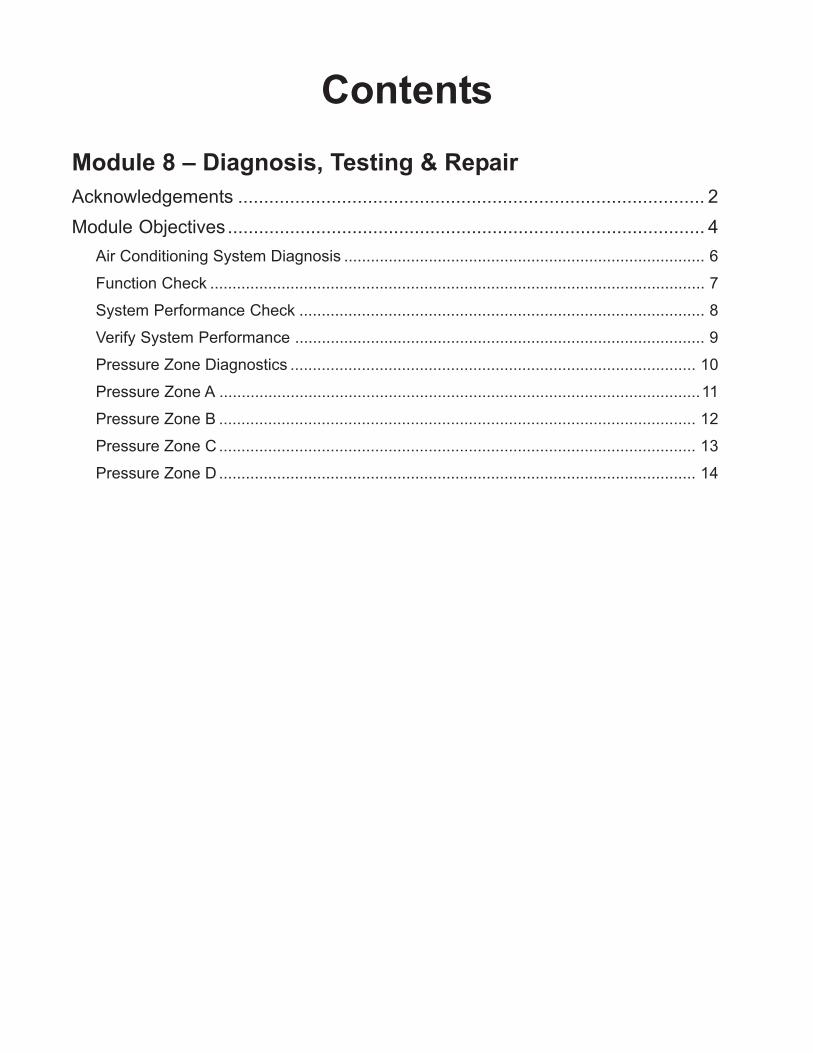
ContentsModule 8 – Diagnosis, Testing & RepairAcknowledgements .......................................................................................... 2Module Objectives............................................................................................ 4
Air Conditioning System Diagnosis ................................................................................. 6Function Check ............................................................................................................... 7System Performance Check ........................................................................................... 8Verify System Performance ............................................................................................ 9Pressure Zone Diagnostics ........................................................................................... 10Pressure Zone A ............................................................................................................11Pressure Zone B ........................................................................................................... 12Pressure Zone C ........................................................................................................... 13Pressure Zone D ........................................................................................................... 14
© 2002 General Motors CorporationAll Rights Reserved
ASE 7- HVAC
Module 8 -Diagnosis, Testing& Repair
8-4
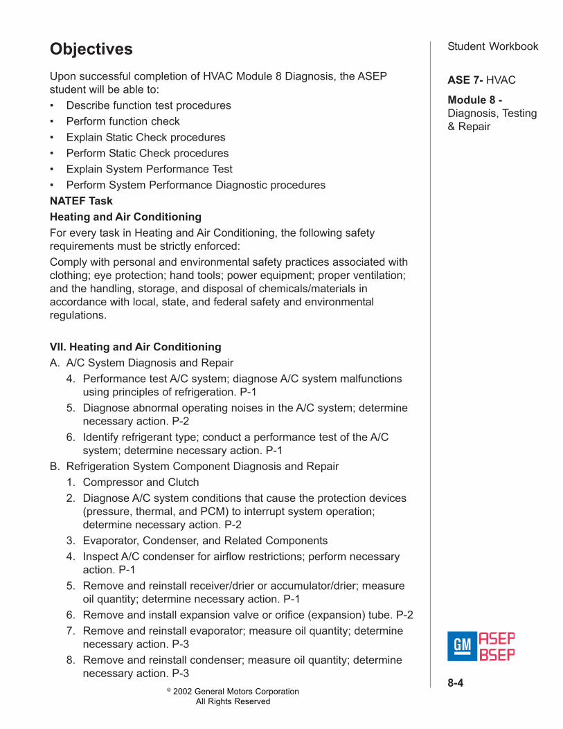
Student WorkbookObjectivesUpon successful completion of HVAC Module 8 Diagnosis, the ASEPstudent will be able to:• Describe function test procedures• Perform function check• Explain Static Check procedures• Perform Static Check procedures• Explain System Performance Test• Perform System Performance Diagnostic proceduresNATEF TaskHeating and Air ConditioningFor every task in Heating and Air Conditioning, the following safetyrequirements must be strictly enforced:Comply with personal and environmental safety practices associated withclothing; eye protection; hand tools; power equipment; proper ventilation;and the handling, storage, and disposal of chemicals/materials inaccordance with local, state, and federal safety and environmentalregulations.
VII. Heating and Air ConditioningA. A/C System Diagnosis and Repair
4. Performance test A/C system; diagnose A/C system malfunctionsusing principles of refrigeration. P-1
5. Diagnose abnormal operating noises in the A/C system; determinenecessary action. P-2
6. Identify refrigerant type; conduct a performance test of the A/Csystem; determine necessary action. P-1
B. Refrigeration System Component Diagnosis and Repair1. Compressor and Clutch2. Diagnose A/C system conditions that cause the protection devices
(pressure, thermal, and PCM) to interrupt system operation;determine necessary action. P-2
3. Evaporator, Condenser, and Related Components4. Inspect A/C condenser for airflow restrictions; perform necessary
action. P-15. Remove and reinstall receiver/drier or accumulator/drier; measure
oil quantity; determine necessary action. P-16. Remove and install expansion valve or orifice (expansion) tube. P-27. Remove and reinstall evaporator; measure oil quantity; determine
necessary action. P-38. Remove and reinstall condenser; measure oil quantity; determine
necessary action. P-3
© 2002 General Motors CorporationAll Rights Reserved
ASE 7- HVAC
Module 8 -Diagnosis, Testing& Repair
8-5
Student WorkbookC. Heating, Ventilation, and Engine Cooling Systems Diagnosis andRepair1. Diagnose temperature control problems in the heater/ventilation
system; determine necessary action. P-2D. Operating Systems and Related Controls Diagnosis and Repair
1. Diagnose malfunctions in the electrical controls of heating,ventilation, and A/C (HVAC) systems; determine necessary action.P-2
4. Diagnose malfunctions in the vacuum and mechanical componentsand controls of the heating, ventilation, and A/C (HVAC) system;determine necessary action. P-2
STC CompetenciesA-7 Competencies for Advanced HVAC System Diagnostics
11045.10W/HD. Diagnose an HVAC System concern using the ACR 2000
1. Identify the system pressures2. Compare system pressures to diagnostic tables3. Identify the causes of abnormal system pressures using the
pressure zone graph and diagnostic tables4. Select the correct repair procedure in response to the pressure
zone graph and diagnostic table
© 2002 General Motors CorporationAll Rights Reserved
ASE 7- HVAC
Module 8 -Diagnosis, Testing& Repair
8-6
Student WorkbookAir Conditioning System DiagnosisThe technician will perform two diagnostic procedures when diagnosingcustomer concerns of “insufficient cooling”. These procedures are theFunction Check and The System Performance Test.The function check provides the technician with three vital pieces ofdiagnostic information. This procedure checks the entire HVAC systemfor proper operation, verifies the customer concern, and providesadditional related symptoms. It also helps to isolate the “root cause” to aparticular sub-system. Technicians who fail to perform this check do notget an accurate picture of the overall system operation.Once the technician has performed the function check and determinedthere is insufficient cooling, it is time to isolate the concern to a sub-system. The system performance test is a function test of the refrigerationsystem. This test requires the technician to perform a preliminary check,measure ambient air temperature, stabilize the system, measuredischarge air temperature, take manifold gauge readings, checkcompressor operation, and “hand check” the system. Depending on thesymptoms found it might be necessary to perform a leak check.
© 2002 General Motors CorporationAll Rights Reserved
ASE 7- HVAC
Module 8 -Diagnosis, Testing& Repair
8-7
Student WorkbookFunction CheckThe functional test can be valuable at diagnosing the root cause of an airconditioning performance concern. By selecting various HVAC operatingmodes, desired temperatures, and fan setting at speeds, specific systemresponses should result. In doing so, the service technician can quicklydetermine if the air conditioning system's electrical, air delivery andrefrigeration system are working properly.The following conditions indicate that the electrical circuits are functioningcorrectly:• The air conditioning blower motor operates at the appropriate speed
with the control (mode) in any position except OFF. Verify that thecompressor clutch also engages.
• The blower motor will not operate in any speed with the control in theOFF position.
The heater A/C control assembly (mode selector) is operating correctlywhen the designated outlets distribute air.The function check provides the technician with three vital pieces ofdiagnostic information. This procedure checks the entire HVAC systemfor proper operation, verifies the customer concern, and providesadditional symptoms. It also helps to isolate the "root cause" to aparticular sub-system. Technicians who fail to perform this check do notget an accurate picture of the overall system operation.
© 2002 General Motors CorporationAll Rights Reserved
ASE 7- HVAC
Module 8 -Diagnosis, Testing& Repair
8-8
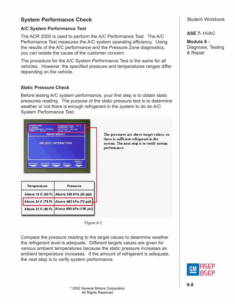
Student WorkbookSystem Performance CheckA/C System Performance TestThe ACR 2000 is used to perform the A/C Performance Test. The A/CPerformance Test measures the A/C system operating efficiency. Usingthe results of the A/C performance and the Pressure Zone diagnostics,you can isolate the cause of the customer concern.The procedure for the A/C System Performance Test is the same for allvehicles. However, the specified pressure and temperatures ranges differdepending on the vehicle.
Static Pressure CheckBefore testing A/C system performance, your first step is to obtain staticpressures reading. The purpose of the static pressure test is to determineweather or not there is enough refrigerant in the system to do an A/CSystem Performance Test.
Compare the pressure reading to the target values to determine weatherthe refrigerant level is adequate. Different targets values are given forvarious ambient temperatures because the static pressure increases asambient temperature increases. If the amount of refrigerant is adequate,the next step is to verify system performance
Figure 8-1,
© 2002 General Motors CorporationAll Rights Reserved
ASE 7- HVAC
Module 8 -Diagnosis, Testing& Repair
8-9
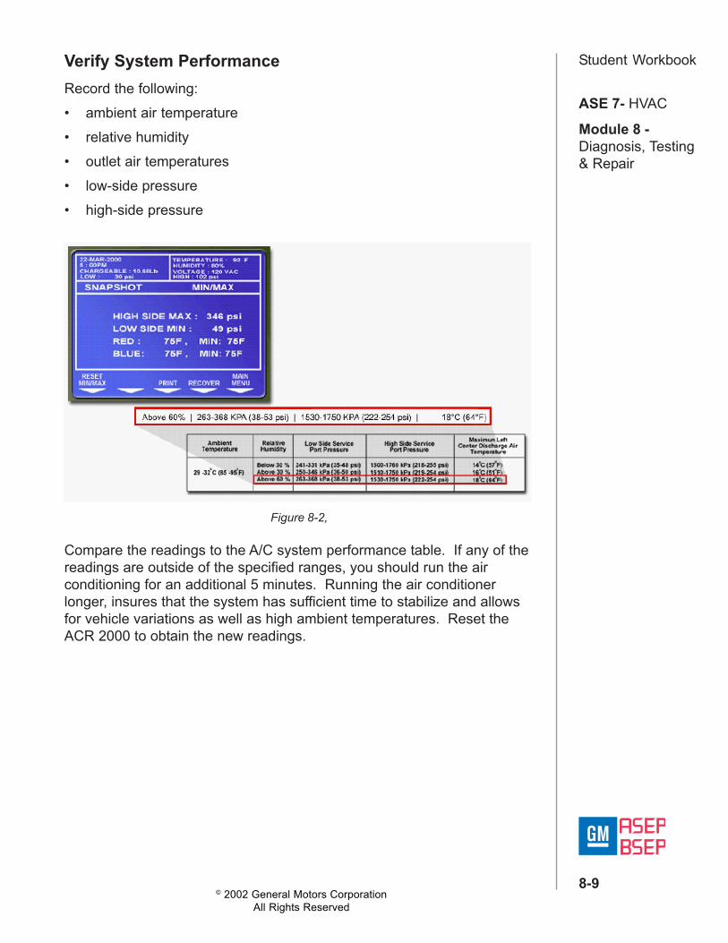
Student WorkbookVerify System PerformanceRecord the following:• ambient air temperature• relative humidity• outlet air temperatures• low-side pressure• high-side pressure
Compare the readings to the A/C system performance table. If any of thereadings are outside of the specified ranges, you should run the airconditioning for an additional 5 minutes. Running the air conditionerlonger, insures that the system has sufficient time to stabilize and allowsfor vehicle variations as well as high ambient temperatures. Reset theACR 2000 to obtain the new readings.
Figure 8-2,
© 2002 General Motors CorporationAll Rights Reserved
ASE 7- HVAC
Module 8 -Diagnosis, Testing& Repair
8-10
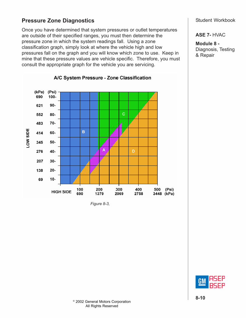
Student WorkbookPressure Zone DiagnosticsOnce you have determined that system pressures or outlet temperaturesare outside of their specified ranges, you must then determine thepressure zone in which the system readings fall. Using a zoneclassification graph, simply look at where the vehicle high and lowpressures fall on the graph and you will know which zone to use. Keep inmine that these pressure values are vehicle specific. Therefore, you mustconsult the appropriate graph for the vehicle you are servicing.
Figure 8-3,
© 2002 General Motors CorporationAll Rights Reserved
ASE 7- HVAC
Module 8 -Diagnosis, Testing& Repair
8-11
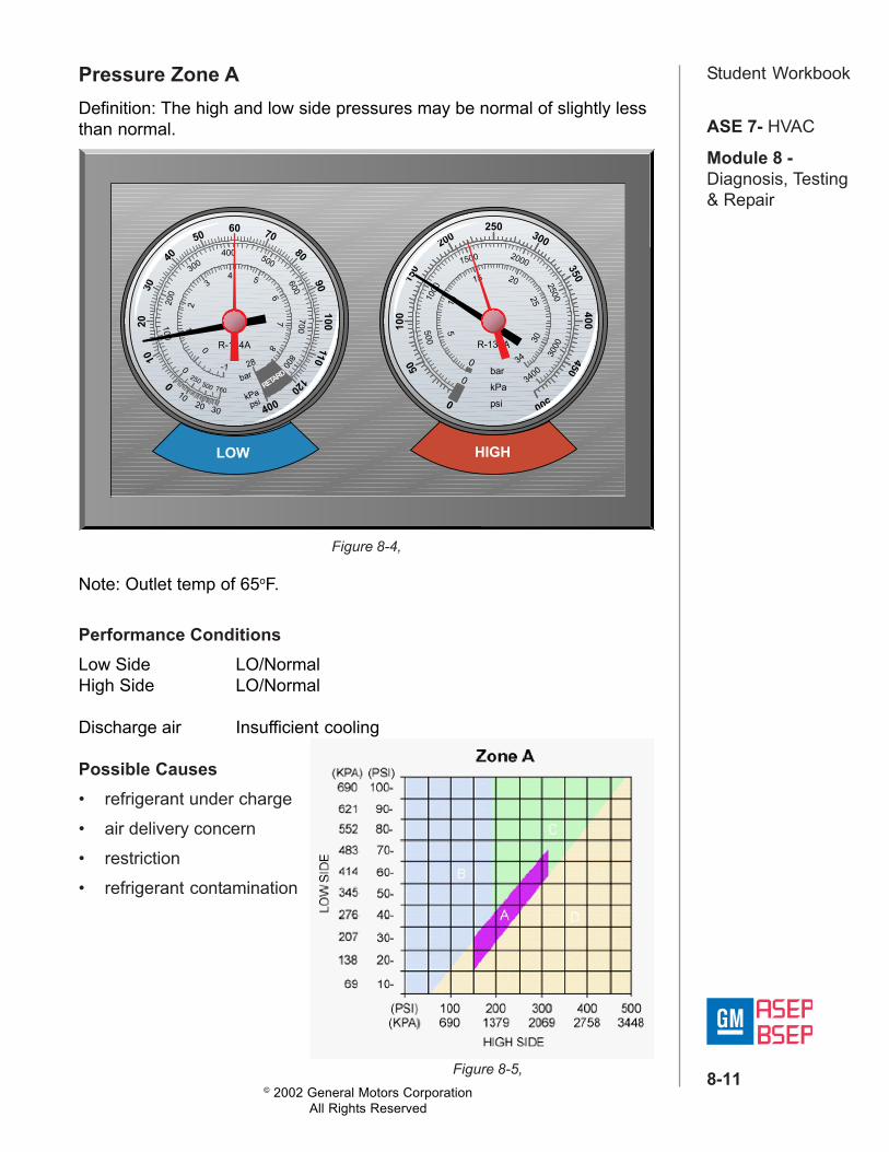
Student WorkbookPressure Zone ADefinition: The high and low side pressures may be normal of slightly lessthan normal.
Figure 8-4,
Figure 8-5,
250
50100
150
200300
350400
450
500
0
500
1000
1500 2000
2500
3000
3400
510
15 20
25
30
34
0
0barkPapsi
R-134A
RETARD
2010
0
30
4050
60 7080
90100
110120
400
100
200
300400 500
700600
800
01
2
34 5
67
80
3020
10
bar
kPapsi
-1250 500 760
28
R-134A
LOW HIGH
Note: Outlet temp of 65oF.
Performance ConditionsLow Side LO/NormalHigh Side LO/Normal
Discharge air Insufficient cooling
Possible Causes• refrigerant under charge• air delivery concern• restriction• refrigerant contamination
© 2002 General Motors CorporationAll Rights Reserved
ASE 7- HVAC
Module 8 -Diagnosis, Testing& Repair
8-12
Student Workbook
Figure 8-6,
Figure 8-7,
250
50100
150
200300
350400
450
500
0
500
1000
1500 2000
2500
3000
3400
510
15 20
25
30
34
0
0barkPapsi
R-134A
RETARD
2010
0
30
4050
60 7080
90100
110
120
400
100
200
300400 500
700600
800
01
2
34 5
67
80
3020
10
bar
kPapsi
-1250 500 760
28
R-134A
LOW HIGH
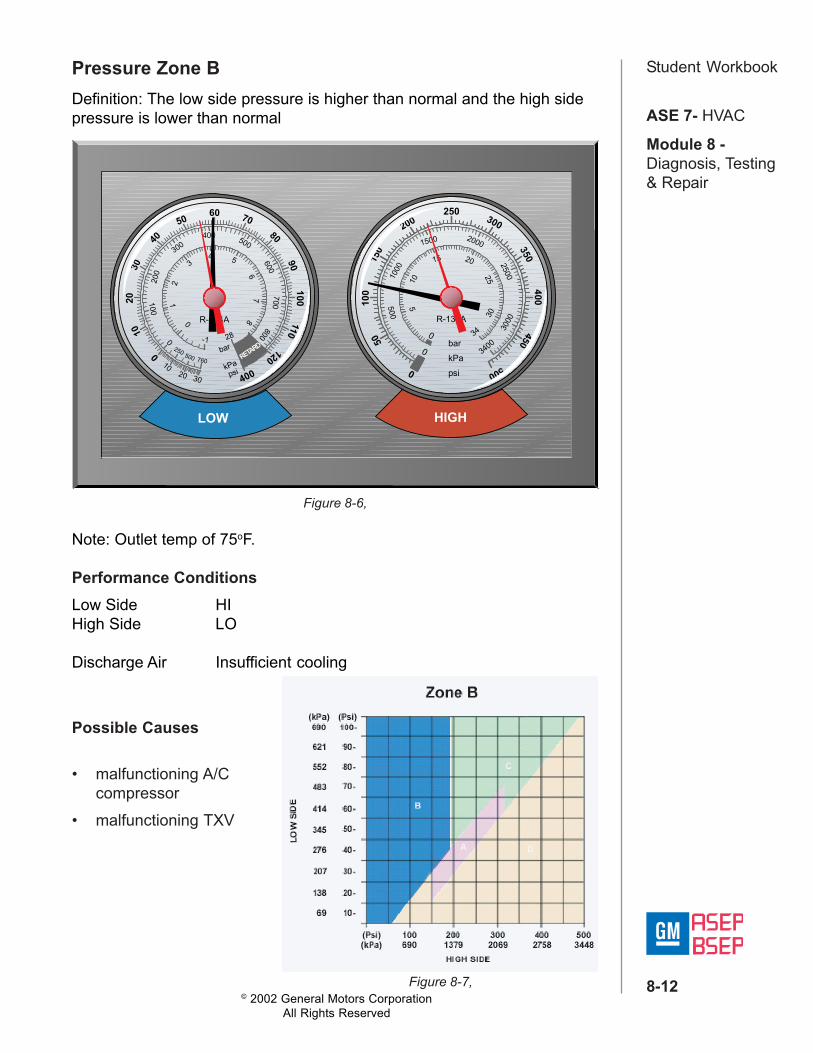
Pressure Zone BDefinition: The low side pressure is higher than normal and the high sidepressure is lower than normal
Note: Outlet temp of 75oF.
Performance ConditionsLow Side HIHigh Side LO
Discharge Air Insufficient cooling
Possible Causes
• malfunctioning A/Ccompressor
• malfunctioning TXV
© 2002 General Motors CorporationAll Rights Reserved
ASE 7- HVAC
Module 8 -Diagnosis, Testing& Repair
8-13
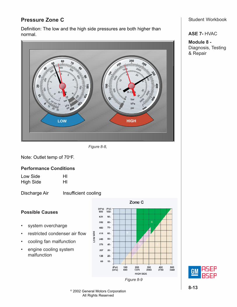
Student WorkbookPressure Zone CDefinition: The low and the high side pressures are both higher thannormal.
Note: Outlet temp of 70oF.
Performance ConditionsLow Side HIHigh Side HI
Discharge Air Insufficient cooling
Possible Causes
• system overcharge• restricted condenser air flow• cooling fan malfunction• engine cooling system
malfunction
Figure 8-8,
Figure 8-9
250
50100
150
200300
350400
450
500
0
500
1000
1500 2000
2500
3000
3400
510
15 20
25
30
34
0
0barkPapsi
R-134A
RETARD
2010
0
30
4050
60 7080
90100
110
120
400
100
200
300400 500
700600
800
01
2
34 5
67
80
3020
10
bar
kPapsi
-1250 500 760
28
R-134A
LOW HIGH
© 2002 General Motors CorporationAll Rights Reserved
ASE 7- HVAC
Module 8 -Diagnosis, Testing& Repair
8-14
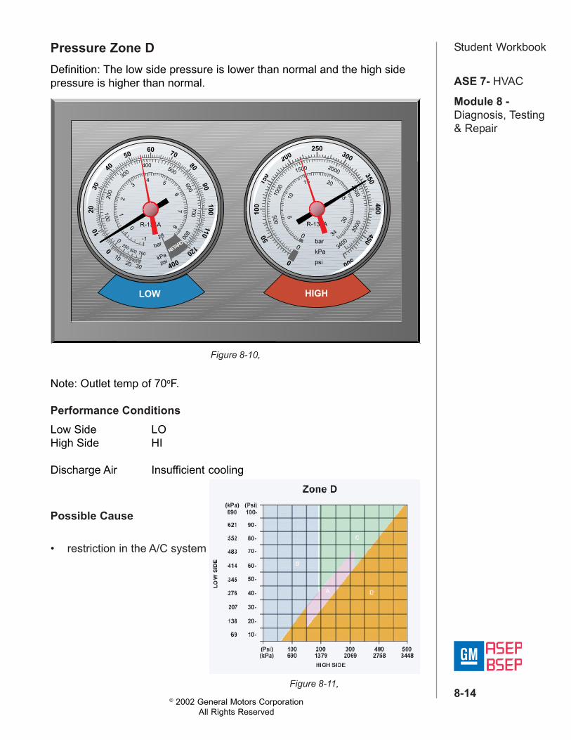
Student WorkbookPressure Zone DDefinition: The low side pressure is lower than normal and the high sidepressure is higher than normal.
Figure 8-10,
Figure 8-11,
250
50100
150
200300
350400
450
500
0
500
1000
1500 2000
2500
3000
3400
510
15 20
25
30
34
0
0barkPapsi
R-134A
RETARD
2010
0
30
4050
60 7080
90100
110
120
400
100
200
300400 500
700600
800
01
2
34 5
67
80
3020
10
bar
kPapsi
-1250 500 760
28
R-134A
LOW HIGH
Note: Outlet temp of 70oF.
Performance ConditionsLow Side LOHigh Side HI
Discharge Air Insufficient cooling
Possible Cause
• restriction in the A/C system