Embed Size (px)
Citation preview
Ashghal – Design Criteria for Highway Structures
PWA IAN 009 Rev A1 Page 1 of 24 September 2013
ASHGHAL
Interim Advice Note No. 009
Design Criteria for Highway Structures
Revision No. A1
EXW-GENL-0000-PE-KBR-IP-00009
SummaryThis Interim Advice Note (IAN) provides information and guidance on the design criteria for highway structures. These design criteria may be superseded in part by subsequently issued amendments to the Qatar Construction Specifications (QCS) or other IANs issued by Ashghal.
This IAN takes immediate effect. The Consultant / Contractor shall review any relevant design documentation issued after the date of issue of these design criteria. If in doubt, Consultants / Contractors should seek guidance from the respective Ashghal Project Manager or designated Programme Management Consultant (PMC) on a scheme specific basis.
This document supersedes IAN 009 Rev 3 dated March 2013. Third parties not working on Ashghal projects make use of this document at their own risk. Paper copies of this document are uncontrolled. Refer to Ashghal’s website for the most recent version.
A1 Sept 2013 Issued for All Relevant Infrastructure Projects DL AM AA3 Mar. 2013 Miscellaneous Revisions IF EDF MG2 June 2012 Issued for Expressway Projects IF EDF MG
Rev Date Reason For Issue Auth Chk App
Ashghal – Design Criteria for Highway Structures
PWA IAN 009 Rev A1 Page 2 of 24 September 2013
Contents
1 Foreword ..................................................................................................................................32 Ashghal Interim Advice Note (IAN) – Feedback Form........................................................... 43 Introduction..............................................................................................................................54 Withdrawn / Amended Standard.............................................................................................55 Implementation ........................................................................................................................ 5Appendix A: Design Criteria for Highway Structures................................................................... 6
Ashghal – Design Criteria for Highway Structures
PWA IAN 009 Rev A1 Page 3 of 24 September 2013
1 Foreword
1.1 Interim Advice Notes (IAN) may be issued by Ashghal from time to time. They define specific requirements for works on Ashghal projects only, subject to any specific implementation instructions contained within each IAN.
1.2 Whilst IANs shall be read in conjunction with the Qatar Highway Design Manual (QHDM), the Qatar Traffic Manual (QTM) and the Qatar Construction Specifications (QCS), and may incorporate amendments or additions to these documents, they are not official updates to the QHDM, QTM, QCS or any other standards.
1.3 Ashghal directs which IANs shall be applied to its projects on a case by case basis. Where it is agreed that the guidance contained within a particular IAN is not to be incorporated on a particular project (e.g. physical constraints make implementation prohibitive in terms of land use, cost impact or time delay) departure from standard shall be applied for by the relevant Consultant / Contractor.
1.4 IANs are generally based on international standards and industry best practice and may include modifications to such standards in order to suit Qatar conditions. Their purpose is to fill gaps in existing Qatar standards where relevant guidance is missing and/or provide higher standards in line with current, international best practice.
1.5 The IANs specify Ashghal’s requirements in the interim until such time as the current Qatar standards (such as QHDM, QTM, etc.) are updated. These requirements may be incorporated into future updates of the QHDM, QTM or QCS, however this cannot be guaranteed. Therefore, third parties who are not engaged on Ashghal projects make use of Ashghal IANs at their own risk.
1.6 All IANs are owned, controlled and updated as necessary by Ashghal. All technical queries relating to IANs should be directed to Ashghal’s Manager of the Design Department, Infrastructure Affairs.
Signed on behalf of Design Department:
____________________________________________________
Abdulla Ahin A A MohdActing Manager of Roads & Drainage Networks Design
Design Management (Roads Section)Public Works Authority
Tel: 44950653Fax: 44950666P.O.Box 22188 Doha - QatarEmail:[email protected]://www.ashghal.gov.qa

Ashghal – Design Criteria for Highway Structures
PWA IAN 009 Rev A1 Page 4 of 24 September 2013
2 Ashghal Interim Advice Note (IAN) – Feedback Form
Ashghal IANs represent the product of consideration of international standards and best practice against what would work most appropriately for Qatar. However, it is possible that not all issues have been considered, or that there are errors or inconsistencies in an IAN.
If you identify any such issues, it would be appreciated if you could let us know so that amendments can be incorporated into the next revision. Similarly, we would be pleased to receive any general comments you may wish to make. Please use the form below for noting any items that you wish to raise.
Please complete all fields necessary to identify the relevant item
IAN title:
IAN number: Appendix letter:
Page number: Table number:
Paragraph number: Figure number:
Description comment:
Please continue on a separate sheet if required:Your name and contact details (optional):Name: Telephone:
Organisation: Email:Position: Address:
Please email the completed form to:
Abdulla Ahin AA Mohd
Acting Manager of Roads and Drainage Networks DesignDesign Management(Roads Section)Public Works Authority
We cannot acknowledge every response, but we thank you for contributions. Those contributions which bring new issues to our attention will ensure that the IANs will continue to assist in improving quality on Ashghal’s infrastructure projects.
Ashghal – Design Criteria for Highway Structures
PWA IAN 009 Rev A1 Page 5 of 24 September 2013
3 Introduction3.1 This Interim Advice Note (IAN), which takes immediate effect, provides requirements with
regard to design criteria for highway structures.
4 Withdrawn / Amended Standard4.1 Not applicable.
5 Implementation5.1 This IAN is to be used with immediate effect on projects as follows:
All Ashghal projects in Design Stage
5.2 The only exceptions are:
Projects where the design of highway structures has been completed.
5.3 If in doubt, Consultants / Contractors should seek guidance from the respective Ashghal Project Manager or designated Programme Management Consultant (PMC) on a scheme specific basis.
Ashghal – Design Criteria for Highway Structures
PWA IAN 009 Rev A1 Page 6 of 24 September 2013
Appendix A: Design Criteria for Highway Structures

ASHGHAL – DESIGN CRITERIA FOR HIGHWAY STRUCTURES
PWA IAN 009 Rev A1 Page 7 of 24
These Design Criteria may be superseded in part by subsequently issued Interim Advice Notes (IANs) or instructions by Ashghal. The designer shall review any such relevant documents issued after the date of these Design Criteria. In the case of any doubt, the Designer should contact the respective Ashghal Project Manager or designated Programme Management Consultant (PMC) for clarification.
DESIGN CRITERIA FOR HIGHWAY STRUCTURES Revision: 03
Date: 21 March 2013
No. Criteria Description
1. Design Standard Design StandardStructures shall comply with the technical requirements of Volumes 1 and 2 of the Highways Agency (UK) Design Manual for Roads and Bridges (DMRB) and BS 5400 (or Eurocode if so directed by ASHGHAL) as implemented by the DMRB unless noted otherwise in this document.
DesignSubject to prior agreement with ASHGHAL, Designers may prepare and present their design calculations to the current (at time of design) metric edition, including revisions, of the American Association of State Highway and Transportation Officials LRFD Bridge Design and Bridge Construction Specification. If this approach is adopted, the HL-93 load shall be multiplied by a factor of 1.85 for all limit states including fatigue. This modification factor shall also be applied to other related loads such as braking, friction centrifugal forces etc. Notwithstanding this approach, the Design Standard (UK DMRB) is as stated above and designers must satisfy themselves that their design is fully compliant with this as they will be contractually required to submit certification accordingly.
CheckingIndependent design checks shall be carried out and documented (including calculations) in accordance with the Design Standard (UK DMRB) as stated above and shall be certified accordingly. The option of using AASTHO – LRFD for checking is not permitted. This does not relieve the Designer of any of his responsibilities for ensuring compliance with the stated Design Standard (UK DMRB).
2. Detailing Unless noted otherwise in this document, structures shall be detailed in accordance with the principals illustrated in the following:1. Bridge Detailing Guide (Publication C543) produced by the Construction Industry Research and Information Association (UK).2. Technical Report Number 72; Durable Post-tensioned Concrete Structures produced by The Concrete Society (UK)
3. Design Life The design life shall be the assumed period for which a structure or part of it is to be used for its intended purpose with anticipated maintenance but without major repair being necessary. Unless stated otherwise in Ashghal Interim Advice Notes, the following shall apply: 120 years Bridges, Underpasses, Tunnels and Retaining Walls 50 years Non replaceable elements of expansion joints (metal runners and anchors), 25 years Deck waterproofing systems, replaceable elements of expansion joints (elastomeric seals), asphaltic plug joints, cover
plates, drainage components, etc. 10 years Protective coatings to concrete
ASHGHAL – DESIGN CRITERIA FOR HIGHWAY STRUCTURES
PWA IAN 009 Rev A1 Page 8 of 24
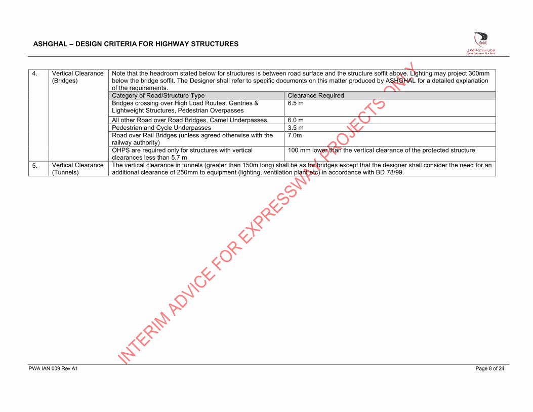
4. Vertical Clearance(Bridges)
Note that the headroom stated below for structures is between road surface and the structure soffit above. Lighting may project 300mm below the bridge soffit. The Designer shall refer to specific documents on this matter produced by ASHGHAL for a detailed explanationof the requirements. Category of Road/Structure Type Clearance RequiredBridges crossing over High Load Routes, Gantries & Lightweight Structures, Pedestrian Overpasses
6.5 m
All other Road over Road Bridges, Camel Underpasses, 6.0 mPedestrian and Cycle Underpasses 3.5 mRoad over Rail Bridges (unless agreed otherwise with the railway authority)
7.0m
OHPS are required only for structures with vertical clearances less than 5.7 m
100 mm lower than the vertical clearance of the protected structure
5. Vertical Clearance(Tunnels)
The vertical clearance in tunnels (greater than 150m long) shall be as for bridges except that the designer shall consider the need for an additional clearance of 250mm to equipment (lighting, ventilation plant etc) in accordance with BD 78/99.
ASHGHAL – DESIGN CRITERIA FOR HIGHWAY STRUCTURES
PWA IAN 009 Rev A1 Page 9 of 24
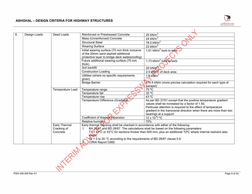
6. Design Loads Dead Loads Reinforced or Prestressed Concrete 25 kN/m3
Mass (Unreinforced) Concrete 24 kN/m3
Structural Steel 78.5 kN/m3
Wearing Surface 23 kN/m3
Initial wearing surface (70 mm thick inclusive of the 20mm sand asphalt additional protective layer to bridge deck waterproofing)
1.61 kN/m2 kerb to kerb.
Future additional wearing surface (75 mm thick)
1.73 kN/m2 kerb to kerb
Soil backfill 20 kN/m3
Construction Loading 2.5 kN/m2 of deck areaUtilities (where no specific requirements given)
1.0 kN/m2
Bridge Barrier ±10.5 kN/m (more precise calculation required for each type of parapet)
Temperature Load Temperature range 75 ºCTemperature fall 32 ºCTemperature rise 43 ºCTemperature Difference (Gradient) As per BD 37/01 except that the positive temperature gradient
values shall be increased by a factor of 1.50. Particular attention is required to the effect of temperature gradient in the transverse direction when there are more than two bearings at a support
Coefficient of thermal expansion 12 x 10-6/ ºCRelative humidity 70%
Early Thermal Cracking of Concrete
Early thermal cracking shall be checked in accordance with either of the following:1. BA 24/87 and BD 28/87. The calculations shall be based on the following parameters:
T1 = 43°C or 53°C for sections thicker than 500 mm, plus an additional 10ºC where internal restraint also exists.T2 = 0 to 20 °C according to the requirements of BD 28/87 clause 5.9.
2. CIRIA Report C660
ASHGHAL – DESIGN CRITERIA FOR HIGHWAY STRUCTURES
PWA IAN 009 Rev A1 Page 10 of 24
Design Loads(continued)
Earth and Water Pressure Loads
1. As per Geotechnical Recommendations. Consideration shall be given to the possibility that the filing material may become saturated or may be removed in whole or in part from either side of the fill-retaining part of the structure.
2. For submerged or partially submerged structures, when checking for uplift of the structure, soil for a depth of at least 1 m from the existing ground level shall be ignored in the computations unless stated otherwise in the project specification. A minimum factor of safety of 1.1 shall be used in the design for uplift when taking dead load only
3. The water table should be conservatively estimated taking into account the effects of tidal and seasonal fluctuations and the recent observation of a rising WT in Doha.
4. Care should be taken to ensure that false water table measurements, resulting from a temporary depression of the water table because of construction activities in the area, are not used in the design.
5. The water table shall not be assumed to be lower than 0.00 QNDT6. The overall factor of safety of earth retaining structures at the Serviceability Limit State shall not be less than:
2.0 for overturning 1.5 for sliding3.0 for bearing capacity1.5 for overall global stability
and shall at all times be equal to or greater than the overall factor used in the geotechnical design.
Differential Settlements
Support settlement and the effects of differential settlement shall be considered in the structural design of bridges. The magnitude of settlements shall not be less than recommended in the Geotechnical Report or calculated in the foundation design. The structural design shall assume a differential settlement between bridge supports in the direction of span of not less than 20mm when founded on spread footings and not less than 5mm for supports founded on piles.
Bearing replacement
The design shall consider a minimum of 20mm uplift between adjacent supports (piers and abutments) during bearing replacement. The uplift shall be considered only in Load Combination 3 as defined in Clause 4.4.3 of BD 37. The Partial Load Factor γfL shall be 1.2 for the Ultimate Limit State and 1.0 for the Serviceability Limit State. The design shall allow for bearing replacement to be carried out with the number of marked traffic lanes on the bridge reduced by not more than 50%. This may be achieved by using hard shoulders or similarly untrafficked areas of the deck as running lanes during bearing replacement. The drawings shall clearly indicate the traffic layout assumed during the replacement of each bearing.
ASHGHAL – DESIGN CRITERIA FOR HIGHWAY STRUCTURES
PWA IAN 009 Rev A1 Page 11 of 24
Design Loads(continued)
Wind Wind load shall be designed in accordance with BS 5400:Part2:clause 5.3 and BD 37/2001The site hourly mean wind speed Vs
The maximum wind gust speed Vd on bridges without live load With live load
The nominal transverse wind load Pt
(in N)
94 km/hr 26 m/s
162 km/hr 45 m/s126 km/hr 35 m/s
0.613Vd2A1CD (N) A1 the solid area (m2)
CD Drag Coefficient for bridges in the gulf CDMAX ≤ 2
The wind speeds are appropriate to a height above ground level of 10m in open level country with an annual probability of being exceeded of 0.02 (50-yr return period)
Seismic Forces (Earthquakes)
1. The design shall follow the general principles set out in AASHTO-LRFD clause 3.10 for Zone 1 and structures shall be designed to resist earthquake motions with an acceleration coefficient of A = 0.09g and importance classification “Essential” Bridges.
2. Site effects, site coefficient and soil profile shall be in accordance with LRFD clause 3.10.5. 3. For the earthquake event, the coincidental traffic load shall be as defined in this document except that a load
factor γfL = 0.5 shall be applied to the traffic loading. 4. The seismic loads are only checked for connections between deck and substructure. 5. When the deck is connected via the bearing to the substructure then only the connection (bearing) need to be
checked for the effect of the seismic loading6. When the substructure is connected monolithically to the deck then the connection of the substructure to both
the deck and its foundation needs to be checkedHighway Live Load - General
Carriageway width:(Note Clause 3.2.9.1 of BD 37/01 is not applicable).
The Carriageway Width is defined as the full deck width between traffic faces of barriers. For application of traffic loads width of carriageway shall be considered from edge of outer barriers ignoring any sidewalks (footpaths) or service reserves.
Notional lane widths ≥ 2.5 m and ≤ 3.65 mNumber of notional lanes
For carriageway width < 5.0m, the carriageway shall be taken to have one notional lane with a width of 2.5m. the loading of the remainder of the carriageway shall as specified in 6.4.1.1
ASHGHAL – DESIGN CRITERIA FOR HIGHWAY STRUCTURES
PWA IAN 009 Rev A1 Page 12 of 24
Design Loads(continued)
Highway bridge live loads
The application of the highway bridge live loads on structures shall be in accordance with BD 37/01. HA loadingHB loadingBoth HA and HB include impact
A formula loading representing normal trafficAn abnormal vehicle unit loading
Loads to be considered The more severe effects of either:Design HA loading orDesign HA loading combined with design HB loading
Type HA loading consists of:1. Nominal uniformly distributed load
(UDL), W
336(1/L)0.67 kN/m of notional lanes for loaded lengths ≤ 50 m36(1/L)0.1 kN/m of notional lanes for loaded lengths >50m & ≤ 1600m Agreed with the relevant authority for loaded lengths > 1600mThe loaded length for the member under consideration, L, shall be the base length of the adverse area
2. Nominal knife edge load (KEL) KEL = 120 kN per notional laneThe UDL and KEL shall be taken to occupy one notional lane, uniformly distributed over the full width of the lane
3. Single nominal wheel load alternative to UDL and KEL
One 100 kN wheel, placed on the carriageway and uniformly distributed over a circular area assuming effective pressure of 1,1 N/mm2
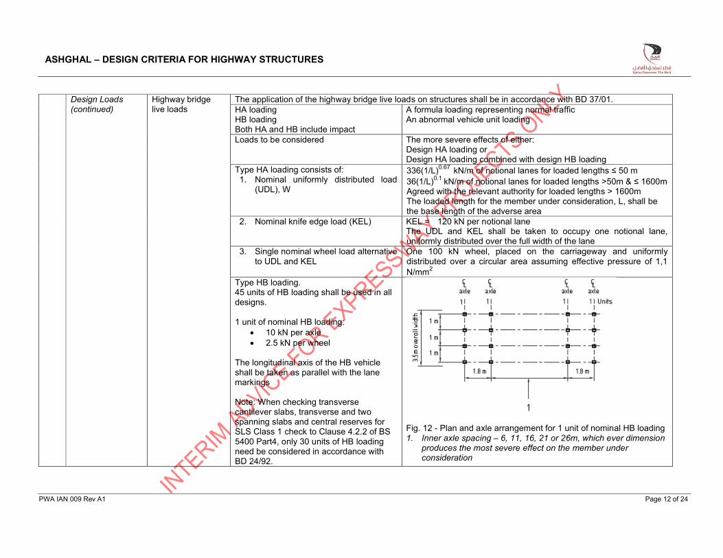
Type HB loading. 45 units of HB loading shall be used in all designs.
1 unit of nominal HB loading: 10 kN per axle 2.5 kN per wheel
The longitudinal axis of the HB vehicle shall be taken as parallel with the lane markings
Note: When checking transverse cantilever slabs, transverse and two spanning slabs and central reserves for SLS Class 1 check to Clause 4.2.2 of BS 5400 Part4, only 30 units of HB loading need be considered in accordance with BD 24/92.
Fig. 12 - Plan and axle arrangement for 1 unit of nominal HB loading1. Inner axle spacing – 6, 11, 16, 21 or 26m, which ever dimension
produces the most severe effect on the member under consideration
ASHGHAL – DESIGN CRITERIA FOR HIGHWAY STRUCTURES
PWA IAN 009 Rev A1 Page 13 of 24
Design Loads(continued)
Live load surcharge Live Load surcharge shall be considered in the design in accordance with BD 37/01 clause 5.8.2. Live load surcharge are as followsHA Load - 10 kN/m2
30 HB Load - 12 kN/m2
45 HB Load - 20 kN/m2
RU loading - 50 kN/m2 (2.63m of fill)RL loading - 30 kN/m2 (1.6m of fill)
Centrifugal Loads The centrifugal loads shall be applied in accordance to BD 37/01, as applicable for the geometry of the bridge
Braking Force Nominal Longitudinal loading due to braking and traction shall be in accordance to BD 37/01 clause 6.10. Accidental load due to skidding shall be considered in accordance to clause 6.11 of BD 37/01
Friction & bearing restraint Load due to friction and bearing restraint shall be derived as per BD 37/01.
Nominal pedestrian live load
For loaded lengths ≤ 36 mFor loaded lengths > 36 m
5 kN/m2
k x 5 kN/m2
k = Nominal HAUDL for appropriate loaded length (in kN/m) x 10L+270
L=the loaded length (in m) in accordance to BD 37/01 Clause 6.5.1 Creep and Shrinkage
Creep and Shrinkage Effects shall be checked in accordance to BS 5400 Part 4. Relative humidity of air corresponding to a value of 70% shall be used for the creep and shrinkage computations.
Shrinkage per unit length
As per BS 5400 Part 4, shrinkage strain at normal exposure for post tension transfer at between 7 days and 14 days after concreting will be 200 x10-6
Pile design Pile designs shall make allowance for the load effects that occur if any pile is constructed such that it deviates from its proposed location and/or inclination by the permitted tolerances
7. Load Combinations
Load combinations applied in the design are those specified in BD 37/01.
8. Stress Check at Transfer for prestress elements
Allowable tensile stress at Transfer is 1.0 N/mm2. Allowable compressive stress limit is as per BS 5400 Part 4.
ASHGHAL – DESIGN CRITERIA FOR HIGHWAY STRUCTURES
PWA IAN 009 Rev A1 Page 14 of 24
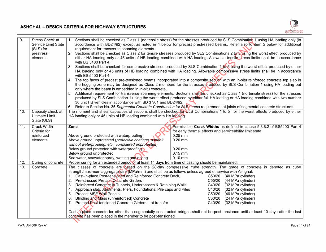
9. Stress Check at Service Limit State (SLS) for prestress elements
1. Sections shall be checked as Class 1 (no tensile stress) for the stresses produced by SLS Combination 1 using HA loading only (inaccordance with BD24/92} except as noted in 4 below for precast prestressed beams. Refer also to item 5 below for additional requirement for transverse spanning elements.
2. Sections shall be checked as Class 2 for tensile stresses produced by SLS Combinations 2 to 5 using the worst effect produced by either HA loading only or 45 units of HB loading combined with HA loading. Allowable tensile stress limits shall be in accordance with BS 5400 Part 4.
3. Sections shall be checked for compressive stresses produced by SLS Combination 1 to 5 using the worst effect produced by either HA loading only or 45 units of HB loading combined with HA loading. Allowable compressive stress limits shall be in accordance with BS 5400 Part 4.
4. The top faces of precast pre-tensioned beams incorporated into a composite section with an in-situ reinforced concrete top slab in the hogging zone may be designed as Class 2 members for the stresses produced by SLS Combination 1 using HA loading but only where the beam is embedded in in-situ concrete.
5. Additional requirement for transverse spanning elements: Sections shall be checked as Class 1 (no tensile stress) for the stresses produced by SLS Combination 1 using the worst effect produced by either full HA loading or HA loading combined with two number 30 unit HB vehicles in accordance with BD 37/01 and BD24/92.
6. Refer to Section No. 35 Segmental Concrete Construction for SLS stress requirement at joints of segmental concrete structures.10. Capacity check at
Ultimate Limit State (ULS)
The moment and shear capacities of sections shall be checked for ULS Combinations 1 to 5 for the worst effects produced by either HA loading only or 45 units of HB loading combined with HA loading.
11. Crack Width Criteria for reinforced elements
Zone
Above ground protected with waterproofingAbove ground unprotected (protective coatings, asphalt without waterproofing, etc., considered unprotected)Below ground protected with waterproofingBelow ground unprotectedSea water, seawater spray, wetting and drying
Permissible Crack Widths as defined in clause 5.8.8.2 of BS5400 Part 4 for early thermal effects and serviceability limit state0.25 mm0.20 mm
0.20 mm0.15 mm0.10 mm
12. Curing of concrete Proper curing for an extended period of at least 14 days from time of casting should be maintained.13. Concrete The classes of concrete are based on the 28-day compressive cube strength. The grade of concrete is denoted as cube
strength/maximum aggregate size (MPa/mm) and shall be as follows unless agreed otherwise with Ashghal:1. Cast-in-place Post-tensioned and Reinforced Concrete Deck, C50/20 (40 MPa cylinder)2. Pre-stressed Precast Concrete Girders C55/20 (44 MPa cylinder)3. Reinforced Concrete in Tunnels, Underpasses & Retaining Walls C40/20 (32 MPa cylinder)4. Approach slab, Abutments, Piers, Foundations, Pile caps and Piles C40/20 (32 MPa cylinder)5. Precast MSE Wall Panels C50/20 (40 MPa cylinder)6. Blinding and Mass (unreinforced) Concrete C30/20 (24 MPa cylinder)7. Pre and Post-tensioned Concrete Girders – at transfer C40/20 (32 MPa cylinder)
Cast-in-place concrete for other than segmentally constructed bridges shall not be post-tensioned until at least 10 days after the last concrete has been placed in the member to be post-tensioned
ASHGHAL – DESIGN CRITERIA FOR HIGHWAY STRUCTURES
PWA IAN 009 Rev A1 Page 15 of 24
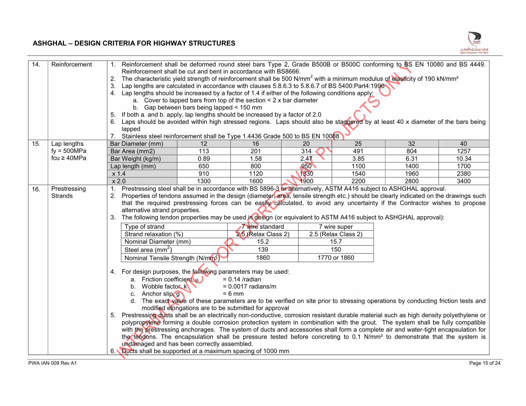
14. Reinforcement 1. Reinforcement shall be deformed round steel bars Type 2, Grade B500B or B500C conforming to BS EN 10080 and BS 4449. Reinforcement shall be cut and bent in accordance with BS8666.
2. The characteristic yield strength of reinforcement shall be 500 N/mm2 with a minimum modulus of elasticity of 190 kN/mm²3. Lap lengths are calculated in accordance with clauses 5.8.6.3 to 5.8.6.7 of BS 5400:Part4:19904. Lap lengths should be increased by a factor of 1.4 if either of the following conditions apply:
a. Cover to lapped bars from top of the section < 2 x bar diameterb. Gap between bars being lapped < 150 mm
5. If both a. and b. apply, lap lengths should be increased by a factor of 2.06. Laps should be avoided within high stressed regions. Laps should also be staggered by at least 40 x diameter of the bars being
lapped7. Stainless steel reinforcement shall be Type 1.4436 Grade 500 to BS EN 10088
15. Lap lengthsfy = 500MPafcu ≥ 40MPa
Bar Diameter (mm) 12 16 20 25 32 40Bar Area (mm2) 113 201 314 491 804 1257Bar Weight (kg/m) 0.89 1.58 2.47 3.85 6.31 10.34Lap length (mm) 650 800 950 1100 1400 1700x 1.4 910 1120 1330 1540 1960 2380x 2.0 1300 1600 1900 2200 2800 3400
16. Prestressing Strands
1. Prestressing steel shall be in accordance with BS 5896-3 or alternatively, ASTM A416 subject to ASHGHAL approval.2. Properties of tendons assumed in the design (diameter, area, tensile strength etc.) should be clearly indicated on the drawings such
that the required prestressing forces can be easily calculated, to avoid any uncertainty if the Contractor wishes to propose alternative strand properties.
3. The following tendon properties may be used in design (or equivalent to ASTM A416 subject to ASHGHAL approval):
Type of strand 7 wire standard 7 wire superStrand relaxation (%) 2.5 (Relax Class 2) 2.5 (Relax Class 2)Nominal Diameter (mm) 15.2 15.7Steel area (mm2) 139 150Nominal Tensile Strength (N/mm2) 1860 1770 or 1860
4. For design purposes, the following parameters may be used:a. Friction coefficient, = 0.14 /radianb. Wobble factor, k = 0.0017 radians/mc. Anchor slip, g = 6 mmd. The exact value of these parameters are to be verified on site prior to stressing operations by conducting friction tests and
modified elongations are to be submitted for approval5. Prestressing ducts shall be an electrically non-conductive, corrosion resistant durable material such as high density polyethylene or
polypropylene forming a double corrosion protection system in combination with the grout. The system shall be fully compatible with the prestressing anchorages. The system of ducts and accessories shall form a complete air and water-tight encapsulation for the tendons. The encapsulation shall be pressure tested before concreting to 0.1 N/mm² to demonstrate that the system is undamaged and has been correctly assembled.
6. Ducts shall be supported at a maximum spacing of 1000 mm
ASHGHAL – DESIGN CRITERIA FOR HIGHWAY STRUCTURES
PWA IAN 009 Rev A1 Page 16 of 24
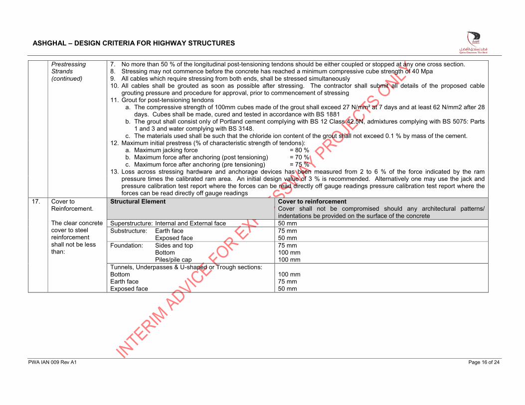
Prestressing Strands (continued)
7. No more than 50 % of the longitudinal post-tensioning tendons should be either coupled or stopped at any one cross section.8. Stressing may not commence before the concrete has reached a minimum compressive cube strength of 40 Mpa9. All cables which require stressing from both ends, shall be stressed simultaneously10. All cables shall be grouted as soon as possible after stressing. The contractor shall submit all details of the proposed cable
grouting pressure and procedure for approval, prior to commencement of stressing11. Grout for post-tensioning tendons
a. The compressive strength of 100mm cubes made of the grout shall exceed 27 N/mm² at 7 days and at least 62 N/mm2 after 28 days. Cubes shall be made, cured and tested in accordance with BS 1881
b. The grout shall consist only of Portland cement complying with BS 12 Class 42.5N, admixtures complying with BS 5075: Parts 1 and 3 and water complying with BS 3148.
c. The materials used shall be such that the chloride ion content of the grout shall not exceed 0.1 % by mass of the cement.12. Maximum initial prestress (% of characteristic strength of tendons):
a. Maximum jacking force = 80 %b. Maximum force after anchoring (post tensioning) = 70 %c. Maximum force after anchoring (pre tensioning) = 75 %
13. Loss across stressing hardware and anchorage devices has been measured from 2 to 6 % of the force indicated by the ram pressure times the calibrated ram area. An initial design value of 3 % is recommended. Alternatively one may use the jack and pressure calibration test report where the forces can be read directly off gauge readings pressure calibration test report where the forces can be read directly off gauge readings
17. Cover to Reinforcement.
The clear concrete cover to steel reinforcement shall not be less than:
Structural Element Cover to reinforcementCover shall not be compromised should any architectural patterns/indentations be provided on the surface of the concrete
Superstructure: Internal and External face 50 mmSubstructure: Earth face
Exposed face75 mm50 mm
Foundation: Sides and topBottomPiles/pile cap
75 mm100 mm100 mm
Tunnels, Underpasses & U-shaped or Trough sections:BottomEarth faceExposed face
100 mm75 mm50 mm
ASHGHAL – DESIGN CRITERIA FOR HIGHWAY STRUCTURES
PWA IAN 009 Rev A1 Page 17 of 24
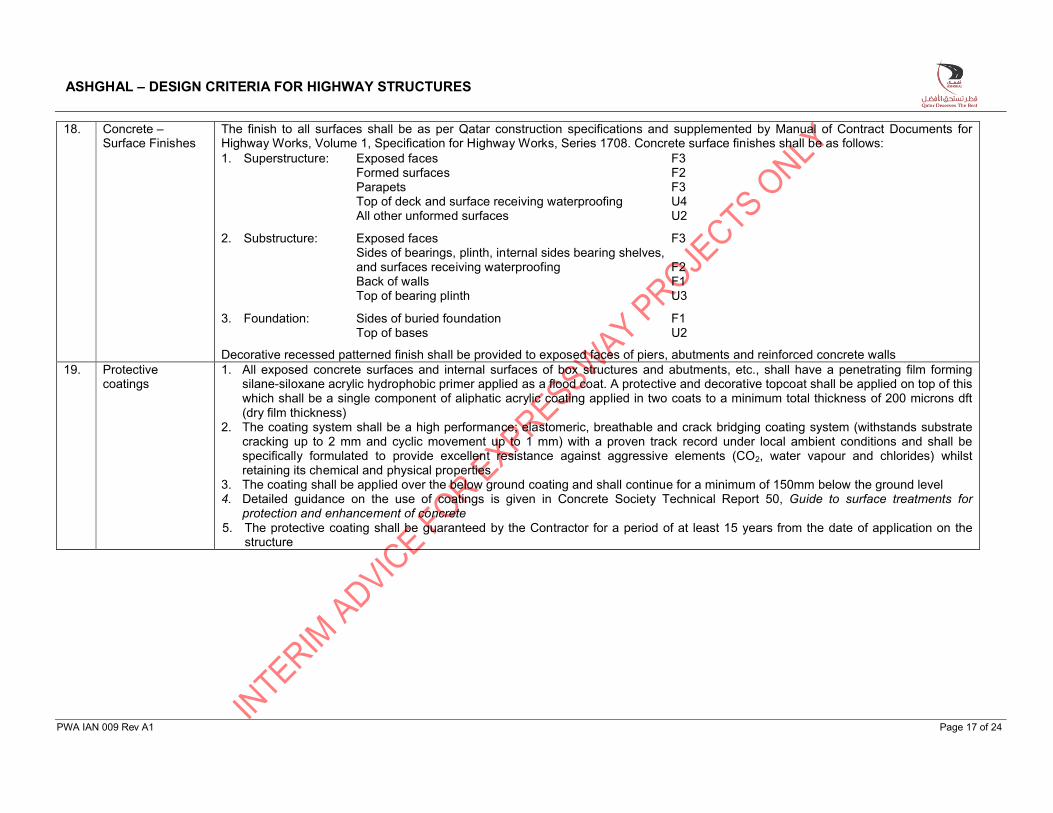
18. Concrete –Surface Finishes
The finish to all surfaces shall be as per Qatar construction specifications and supplemented by Manual of Contract Documents for Highway Works, Volume 1, Specification for Highway Works, Series 1708. Concrete surface finishes shall be as follows:1. Superstructure: Exposed faces F3
Formed surfaces F2Parapets F3Top of deck and surface receiving waterproofing U4 All other unformed surfaces U2
2. Substructure: Exposed faces F3Sides of bearings, plinth, internal sides bearing shelves, and surfaces receiving waterproofing F2Back of walls F1Top of bearing plinth U3
3. Foundation: Sides of buried foundation F1Top of bases U2
Decorative recessed patterned finish shall be provided to exposed faces of piers, abutments and reinforced concrete walls19. Protective
coatings1. All exposed concrete surfaces and internal surfaces of box structures and abutments, etc., shall have a penetrating film forming
silane-siloxane acrylic hydrophobic primer applied as a flood coat. A protective and decorative topcoat shall be applied on top of this which shall be a single component of aliphatic acrylic coating applied in two coats to a minimum total thickness of 200 microns dft (dry film thickness)
2. The coating system shall be a high performance; elastomeric, breathable and crack bridging coating system (withstands substrate cracking up to 2 mm and cyclic movement up to 1 mm) with a proven track record under local ambient conditions and shall be specifically formulated to provide excellent resistance against aggressive elements (CO2, water vapour and chlorides) whilstretaining its chemical and physical properties
3. The coating shall be applied over the below ground coating and shall continue for a minimum of 150mm below the ground level4. Detailed guidance on the use of coatings is given in Concrete Society Technical Report 50, Guide to surface treatments for
protection and enhancement of concrete5. The protective coating shall be guaranteed by the Contractor for a period of at least 15 years from the date of application on the
structure
ASHGHAL – DESIGN CRITERIA FOR HIGHWAY STRUCTURES
PWA IAN 009 Rev A1 Page 18 of 24
20. Bearings 1. Bearings shall comply with Ashghal interim Advice Note 006 - Specification for Bridge Bearings.2. The design shall consider a minimum of 20mm uplift between adjacent supports (piers and abutments) during bearing replacement3. Typically bearing types which are acceptable for installation at bridge supports are elastomeric bearings and proprietary mechanical
bearings such as pot and spherical bearings 4. Elastomeric bearings shall be positively located on bearing plinths to prevent them walking during bridge expansion and contraction5. Proprietary bearings shall be designed by the Contractor’s specialist supplier. 6. All bearings shall be replaceable. The bearing shall be recessed into adaptor plates or be of such construction as to facilitate
removal of the bearing from the installed position without damage to any part of the bearing or the surrounding material after the relevant structural member has been raised by a maximum of 15mm or the distance specified. Mechanical bearings shall be provided with top and bottom adapter plates to allow for simple removal
7. Refer to Design Loads for permitted traffic restrictions during bearing replacement.8. Jacking points for the location of jacks during bearing replacement shall be indicated on drawings. 9. Bearings shall be located on bearing plinths out of reach of any possible flooding of abutment galleries and pier tops. It is
preferable to reduce the thickness of the dropdown plinth from the deck soffit and to rather increase the height of the bearing plinth to accommodate the bearing within the gap available between the pier top and the deck soffit.
10. Tension/up-lift bearings are not permitted unless agreed in writing with Ashghal.
21. Friction Bearing Restraint
1. Loads due to frictional bearing restraint to be derived in accordance to BD 37/01 & BS 5400 Part 9.2. Typically coefficient of friction of pot bearings which incorporates greased PTFE sliding surface shall be a minimum of 4%
ASHGHAL – DESIGN CRITERIA FOR HIGHWAY STRUCTURES
PWA IAN 009 Rev A1 Page 19 of 24
22. Expansion Joints 1. All expansion joints shall comply with the requirements of BD 33/94 ((Expansion Joints for use in Highway Bridge Decks) and a Departmental Standard and Advice note on Design for durability, BD 57/1 and BD 57/01
2. Expansion joints are required to be approved by ASHGHAL before they may be installed on bridge decks. The requirements for approval are set out in Annex A of BD 33/94
3. The number of expansion joints on a bridge shall be kept to an absolute minimum and if possible they shall be provided at thebridge abutments only
4. Where expansion joints are used, provision should be made for inspecting them and the structure underneath, and the details should be based on the assumption that joints will leak and will not provide protection against ingress of water
5. Appropriate drainage paths for the leakage should be provided which ensure that water cannot gain access to prestress anchorages or bearings and that water is not allowed to pond. This is especially important if intermediate joints have to be located over piers, in ensuring that drainage paths are kept clear of anchorages, because it is difficult to provide an inspection gallery.
6. Expansion joints shall be designed to the following characteristicsa. To accommodate the full designed movement range of the adjacent decks ending at the joint. The movements could be
horizontal (longitudinal and transverse), vertical and/or rotationalb. To sustain all loads subjected to it from the passing traffic without damage to the surfacing or the supporting structure during
their working lives. The loads shall be as stated in BD 33/94 c. To be fully watertight at all points, from parapet to parapet, throughout its entire movement range. The joint shall be bent up at
ends within the traffic barriers at an angle of 45° to the horizontal to ensure that water is at all times contained within the roadwayd. To provide a smooth ride and skid resistance for passing traffic over the joint
7. Strip seals and modular expansion joints with anchors cast into the deck are preferred over bolted down joints and preformed elastomeric compression joint seals which are not recommended because of past experiences of failures
8. It is recommended that the neoprene or rubber seals are at least 6mm in thickness9. Joints in tunnels, underpasses and long approach retaining walls should adhere to the following:
a. Expansion joints shall be spaced apart at a maximum of 30mb. Partial contraction joints shall be located at the mid length of each segmentc. Stainless steel dowels shall be used at all expansion joints in tunnels and underpassesd. Be provided with re-injectable hoses for the sealing of any future leakage which may require repeating a number of times
10. Gap-widtha. The gap width between the supporting elements of the joint on the abutment backwall and the deck immediately below the
expansion joint should account for possible future forward rotation of the abutmentb. A gap of at least 800mm shall be provided between abutment walls & deck ends to provide access for maintenance of the joints.c. Where access to concrete faces will not be available in the future and where leakage is likely to occur such as at intermediate
expansion joints at the top of piers we recommend the use of stainless steel for all reinforcement adjacent to the concrete surfaces in the joint gap
d. The maximum width of open gap at roadway level which is acceptable for motor vehicles is 80mm. If the expansion joint gap is sealed with anything other than a load bearing element it shall be considered to be open
e. Drip moulds shall be provided immediately below the concrete corbel supporting expansion joints at the abutments and piers toprevent water from accessing the face of concrete elements and prestressing anchorages
11. Performance guarantees shall be provided by the contractor to ensure that the expansion joint systems perform as designed, remain watertight and are corrosion free for a period of 15 years after construction
ASHGHAL – DESIGN CRITERIA FOR HIGHWAY STRUCTURES
PWA IAN 009 Rev A1 Page 20 of 24
23. Parapets 1. The requirements stated here are minimum requirements. The designer shall carry out a risk assessment appropriate to each individual location to determine if any additional restraint measures are necessary.
2. Parapets shall comply with either BS EN 1317 or NCHRP Report 350. The standard to be adopted shall be agreed with ASHGHAL in advance of design commencing. To avoid confusion, only one design standard shall be used on any construction contract.
3. The minimum level of containment, unless noted otherwise in this document, shall be: a. H2 as per BS EN 1317-2 orb. TL4 as per NCHRP Report 350
4. For bridges crossing railways, bridges carrying High Load Routes and bridges crossing critical or hazardous infrastructure, the minimum level of containment shall be:a. H4a as per BS EN 1317-2 orb. TL5 as per NCHRP Report 350.
5. The minimum requirements for parapet heights are shown in the table below:
Use ContainmentHeight (mm)
Not over railway Over railway
Bridges without pedestrian and cyclist accessH2 / TL4 1000 -H4a / TL5 1500 1500
Bridges with pedestrian accessH2 / TL4 1150 -H4a / TL5 1500 1500
Bridges with cyclist accessH2 / TL4 1400 -H4a / TL5 1500 1500
6. The dynamic deflection of the parapet as defined in BS EN 1317-2 shall be such that, when the parapet is displaced laterally by the full dynamic deflection, no lateral gap exists between the parapet and the edge of the supporting bridge deck.
7. Where parapets complying with BS EN 1317 are proposed, the Working Width shall be indicated on the drawings, 8. The exact height, pattern and material shall be determined following consultation with ASHGHAL as to reflect client aspiration for
the integrated aesthetical and urban design for highways and structures.9. Reinforced concrete parapets shall be F Shape.10. Other metallic post and rail parapet types, including aluminium, galvanised steel or stainless steel or combined metal and F shape
may be proposed for approval by ASHGHAL.11. Visibility and sighting analysis shall be carried out for all parapets. 12. Studies shall be undertaken to determine if additional noise or privacy barriers are required. The total height shall be 2.4m.13. All dowel bars used in parapets shall be stainless steel.
24. Vehicle collision with structures
1. Elements of structures located within 9000 mm to the edge of roadway, shall be designed for vehicle collision loads in accordance with the recommendations of BD 60/04 and BD 37/01.
2. Elements of structures in the median or adjacent to the carriageway will be protected by F Shape concrete barriers. Barrier Units should be at least 6 m long, built on foundation and connected/articulated horizontally (through hinge/rod or similar).
ASHGHAL – DESIGN CRITERIA FOR HIGHWAY STRUCTURES
PWA IAN 009 Rev A1 Page 21 of 24
25. Vessel collision with structures
1. Shall be in accordance with the regulatory authorities requirements and shall be subject to approval by ASHGHAL2. In navigable waterways where vessel collision is anticipated, structures shall be:
a. Designed to resist vessel collision forces, and/orb. Adequately protected by fenders, dolphins, berms, islands, or other sacrifice-able devices
3. In determining vessel collision loads, consideration shall be given to the relationship of the bridge to:a. Waterway geometry,b. Size, type, loading condition, and frequency of vessel using the waterway,c. Available water depth,d. Vessel speed and direction, ande. Structural response of the bridge to collision
26. OHPS OHPS are required only for structures with vertical clearances less than 5.7 m and shall be designed to resist highway collision load in accordance with the UK Highways Authority DMRB BD 65/97 (Design Criteria for Collision protection Beams)
27. Approach Slab Approach slabs shall be provided at both ends of the bridges and on cut and cover structures and it will be connected to the abutment wall via stainless steel bars. The approach slab shall be at least 6m long, except at integral structures where its length may be reduced to 3m. The approach slab shall cover the entire carriageway width, verge, median and footpaths.
28. Waterproofing of bridge decks
1. All bridges shall receive a liquid (spray applied) membrane of at least 2 mm in thickness on the peaks of ridged surfaces and 3 mm on flat surfaces. The thickness shall also not exceed 4mm.
2. All waterproofing membranes shall comply with the requirements of BD 47/88 and BA 47/99. 3. Sheet membranes are not recommended4. The waterproofing should be continuous and cover the entire deck between parapet upstands including footways, central reserves,
verges, service bays and under kerbs. Particular attention should be paid to sealing the waterproofing membrane at its edges and around interruptions
5. Where mass concrete is placed on top of the deck or tunnel base slabs, the waterproofing membrane shall be installed below the mass concrete. In such cases an aggregate shear key will be provided by introducing, by hand, a 16/30 grade silica sand aggregate into the 2nd coat of waterproofing membrane while it is still in liquid state. The coverage will be 1 kg/m2
6. Horizontal chases, 6mm wide x 6mm deep, should be provided on all vertical faces of deck elements such as parapets and kerbs, for the termination of membranes
7. It is preferable that the membrane is applied in two coats each being of a contrasting colour; however applied, it should be proved using ”pin-hole” detection equipment, which will give reasonable assurance of the integrity of the membrane
8. The adhesion of the membrane to the deck shall be measured in accordance with BS 3900:E10:1989 prior to applying the wearing course (asphaltic surfacing) by doing random checks, a minimum of 3 per 500 m2 or a minimum of 3 tests on decks of less than 500 m2. The minimum bond strength should be 0.3 N/mm2
9. A tack coat shall be applied to the waterproofing membrane (as a bonding agent) prior to the application of the deck surfacing10. Where the tack coat is of the type activated by the heat of the succeeding bituminous layer, the rolling temperature of this layer
shall be sufficient to ensure adhesion. The temperature of the asphalt at the time of installation shall be in accordance with the manufacturer’s specifications of the membrane system being used. Tack coats between the waterproofing membrane and overlying asphalt shall have a minimum softening point of 80 °C.
11. The waterproofing system shall have a current British Board Agrément (BBA) Road and Bridges Certificate and should be guaranteed by the contractor for 15 years from the date of final acceptance of the system. Adhesion between the waterproofing membrane and the wearing course should be included in the guarantee.
ASHGHAL – DESIGN CRITERIA FOR HIGHWAY STRUCTURES
PWA IAN 009 Rev A1 Page 22 of 24
29. Waterproofing of structural elements below ground level
All concrete surfaces below the ground level shall be protected with waterproofing membrane conforming to the project specification and as applicable to QCS 2010. The waterproofing will be terminated 150 mm above the ground level, protective board or other means will be provided to protect the waterproofing membrane. The protective coating will be applied over the below ground coating/waterproofing and shall continue for a minimum of 150 mm below the ground level.
30. Waterproofing of partially or fully submerged tunnels and vehicle underpasses
1. Waterproofing shall comply with Ashghal Interim Advice Note 004 - Specification for Waterproofing of Cut and Cover Tunnel and Underpass Highway Structures.
2. The waterproofing system shall ensure watertightness and provide long term protection to the concrete from ingress of waterborne chlorides or other deleterious materials
3. It shall be designed to be fully effective over the design life of the structure and shall be formulated to allow application in the hot climatic conditions encountered in the Middle east
4. Waterproofing systems shall be installed strictly in accordance with the manufacturers specifications and recommendations.5. “Stick on” and “torch on” sheet membranes are not permitted6. All components and elements of the waterproofing system shall be proven to work together. They shall be a single source of
responsibility and performance of the products

ASHGHAL – DESIGN CRITERIA FOR HIGHWAY STRUCTURES
PWA IAN 009 Rev A1 Page 23 of 24
31. Drainage 1. Bridges – The deck drainage shall be considered during the early stages of design because of the large implications on the final bridge configuration. The following is recommended in order of preference:a. Do away with drains on structures if at all possible. Design the roadway with adequate slopes both in the longitudinal and the
transverse direction to ensure that water does not accumulate in the roadway during a rain storm. Allow for wider shoulders to ensure that this does not happen. In such cases water draining off at both ends of the bridge should be channelled into largediameter downchute pipes, with inlets and outlet structures, draining into the drainage system below. This is required to prevent the erosion of the approaches.
b. If the structure is too long and the roadway design does not allow for a “no drains” solution design free falling drain systems to be at close and regular intervals, located in the roadway adjacent to kerbs, short vertical 150 to 200mm diameter pipes, with no bends if possible. Provide large drip moulds on the circumference of the pipes where they exit the concrete section to prevent water dripping down the deck cantilevers. Free falling systems should extend below the underside of deck cantilevers or deck soffit and be placed away from the piers and faces of box girder webs to avoid wind-driven spray on bridge members. Care must be taken that no erosion or damage occurs underneath. Water should never be dumped on a surface that lacks erosion protection, such as rip-rap, a paved slab, splash block, or an open basin. Given that it seldom rains in Doha this inconvenience will be temporary and should be acceptable as long as drain pipes are also located away from pedestrian walkways, roadways and railways existing below the bridge. This strategy is particularly suited to rural applications and should be used with care and only where appropriate in urban areas.
c. If drainage pipework cannot be avoided, then the following criteria should be adhered to:i. Pipe gradients should be maximized to increase flushing action;ii. Consider oversized pipes to reduce the potential for blockages;iii. Provide traps with simple access for cleaning wherever feasible ; iv. Bends & Turns to be kept to an absolute minimum;v. Pipe material must be robust and non-corroding (internally and externally). Use of stainless steel or ductile iron;vi. Pipe joints must be robust and as leak proof as possible. Consider the use of bolted flanged joints;vii. Roding access to be provided to all pipe runs;viii. Particular attention is required where pipes pass through the structure, particularly at abutments where relative movement
is anticipated between the deck & the sub-structure.ix. Lengths of pipes to be cast into structures should be minimised. These lengths should consist of single pipe unit without
any joints cast into the concrete.x. Pipe Supports – these must be robustxi. The use of externally surface mounted pipes should be avoided unless absolutely necessary.
2. Tunnels and Underpasses – Stormwater runoff shall preferably be collected in sumps accessible for maintenance. Pumps and sumps are preferably located to the side of tunnels where access can be gained through a doorway for maintenance.
3. Retaining walls and abutments perforated drainage pipes shall be provided adjacent to the bottom of retaining wall / abutment stem to be connected to the drainage system/network.
ASHGHAL – DESIGN CRITERIA FOR HIGHWAY STRUCTURES
PWA IAN 009 Rev A1 Page 24 of 24
32. Fire The effect of fire on concrete, reinforcement and prestress shall be considered where appropriate. Tunnels shall comply with the requirements of Ashghal interim Advice Note 020 - Road Tunnel Fire and Life Safety Systems.
33. Proposed Arrangement for Inspection and Maintenance
1. For flyovers, two (one at each end) access holes of 800x1000 mm shall be provided in the bottom slab of each accessible cell (void) in single and multiple cell box girders, to ensure proper ventilation during inspection and/or maintenance work. Access openings, 800 mm in diameter minimum, shall be provided through the deck diaphragms to facilitate the movement inside the deck between different spans wherever this is possible.
2. Bridge joints and bearings at abutments shall be accessible through an inspection gallery at each abutment. The preferred location for the gallery doors shall be on the front of the abutment; however in special cases it will be acceptable to locate them on the sides of the abutment. Only one door will be sufficient to access the gallery
3. The exposed height of abutment below the soffit of the deck shall never be less than 2 m34. Lighting Lighting columns/standards shall be located outside the parapets. Dedicated corbels shall be provided as required.35. Segmental
Concrete Construction
1. Concrete units for segmental construction shall be match cast.2. Joints in segmental construction shall be sealed/closed with a proprietary epoxy adhesive which is manufactured specifically for
such applications and suitable for the climatic conditions in Qatar. Dry joints are not permitted.3. No tensile stress is permitted at joints for SLS Combinations 1 to 5 using the worst effect produced by either HA loading only or 45
units of HB loading combined with HA loading.