Embed Size (px)
Citation preview
Lawrence Technological University
ASHRAE 2015
Integrated Sustainable Building Design (ISBD)
Student Design Competition
Lawrence
Technological
University
Architectural Engineering
Department
HADIEL MOHILLDEAN
Architectural Engineering
Graduation: Spring 2016
Phone: (313) 605-4440
E-mail: [email protected]
ZECHARIAH VINSON
Architectural Engineering
Graduation: Spring 2016
Phone: (586) 623-1615
E-mail: [email protected]
FARAH ANONI
Architectural Engineering
Graduation: Spring 2016
Phone: (248) 773-2013
E-mail: [email protected]
DANIEL FAORO
RA – ASHRAE Associate
Faculty Advisor
Phone: (248) 204-2856
E-mail: [email protected]
MARK DRIEDGER
Faculty Advisor
Phone: (905) 580-4820
E-mail: [email protected]
Lawrence Technological University
Executive Summary
The main objective of this proposal is to design a new three story junior college classroom building
in Doha, Qatar which showcases modern sustainable design by accounting for energy efficiency, health and
safety, occupant comfort, functionality, longevity, flexibility, and serviceability. This project is introduced
and sponsored by ASHRAE Annual Student Design Project Competition. Therefore, to meet the
requirements of high energy performance buildings, ASHRAE standards have been used as a guideline
throughout the entire design development phases of the project for example, ASHRAE 189.1-2014. The
Education City in Qatar has been selected as the potential location for the project since it is considered a
sustainable developing educational district that embraces international universities, K-12 schools, and
research centers. The project design process started with collecting information about the general climatic
conditions of Doha, Qatar using Climate Consultant 6.0 software, using Abu Dhabi as the closest proxy
site. Based on charts and annual collected data, Doha, Qatar is categorized under Zone 1 based on ASHRAE
criteria of hot and humid climates. The sustainable site has been developed considering, environmental
challenges, traffic flow, safety, cultural background, and economy. Also, a sustainable integrated parking
lot area has been developed for students, faculty members, and visitors for long term parking. Sustainable
features have been integrated to the parking area such as, solar PV panels, LED lights, rain water collection
system, and eco-pavement system to promote the usage of renewable energy resources on site.
In addition, the design of the proposed building has been developed using bio-climatic strategies
such as shading, passive cooling, passive ventilation, minimum solar heat gain, and maximum controlled
daylighting which collectively helped to achieve an energy efficient design that best responds to the climatic
conditions and the natural environment of Doha, Qatar. Also, materials have been selected to be
prefabricated, recyclable, durable, and functional to allow for a better construction waste management,
minimum maintenance, and less impact on the environment. The majority of the materials are locally
supplied to support local businesses while reducing the cost associated with shipping. The building interior
has been designed to meet the main function of the building to enhance students’ educational experience.
The building includes classrooms, administration offices, media center, workshops and meeting areas. The
spatial organization has been designed to reflect some of the valuable design strategies that have been
expressed in the work of the great architect Louis Kahn to create a unique and transformative learning
environment.
Taking into consideration the requirements for high energy performance buildings, building
systems- structural, mechanical, lighting, plumbing, and fire detection systems -have been designed
carefully to increase energy efficiency, reduce heat loads and water consumption, improve indoor air quality
and safety, eliminate maintenance, and use renewable energy resources. For instance, the PV solar system
on the roof of the third floor accommodates 16% of the total power load required by the building with an
annual saving of $25,937. In addition, the mechanical system achieves annual savings of $91,554.15. Using
low flow plumbing fixtures also allowed for a 33.1% overall reduction in the total number of gallons used
by the building annually. Both prescriptive and performance paths have been considered along with the
mandatory provisions when designing each of the proposed building system to comply with ASHRAE
standards.
Calculations have been conducted using excel spread sheets, Revit Autodesk 3D software, PVWatts
calculator to calculate building loads and energy savings as well as sizing systems to accommodate for the
building energy demands. Moreover, cost analysis have been produced to assure that the proposed design
meets the per-specified budget of $200.00/sf. The total project cost is 169.24 $/sf. Moreover, LEED
standards were projected to rate the building at platinum level.
Lawrence Technological University
ACKNOWLEDGMENTS
The proposed project required a good quality of work, research, and dedication. However, the
outcomes would not have been at this level of quality if we have not had the support and
guidance of many faculty members and advisors. Therefore, we would like to extend our sincere
gratitude to all of them. First of all, we would like to thank our faculty advisors professor Daniel
Faoro and Mark Driedger for sharing their superior knowledge and experience to accomplish this
project. Also, we are thankful for the continuous support provided by professor Filza Walters,
Ralph Nelson, Robert Roop, Robert Stevenson, Janice Means, and Faris Habba in the completion
of this project.
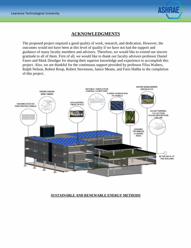
SUSTAINABLE AND RENEWABLE ENERGY METHODS
Lawrence Technological University
CONTENTS
Integrated Susteinable Design Building ASHRAE – 2015
Student Design Competiton
SECTION PAGE
1 Introduction……………………………………………………………………………..…(1)
2 Climate Analysis……………………………………………………………......................(2)
3 Site Analysis………………………………………………………....................................(3)
4 Site Design………………………………………………………………………………...(5)
5 Building Design Strategies…………………………………………………………….….(10)
6 Building Program & Spatial Organization………………………………………….…….(12)
7 Structural System Design…………………………………………………........................(14)
8 Envelope Design………………………………………………………………………….(15)
9 Lighting System Design……………………………………………………………….….(19)
10 Photovoltaic System Design ………………………………………………………….…..(22)
11 Plumbing and Fixtures Selection………………………………………….........................(23)
12 Mechanical System Design…………………………………………………………….....(25)
13 Energy Model Comparison ……………………………………………............................(31)
14 Fire Detection, Protection, and Supression System……………………............................(34)
15 Cost Analysis…………………………………………………………………………......(35)
16 Appendices
Lawrence Technological University
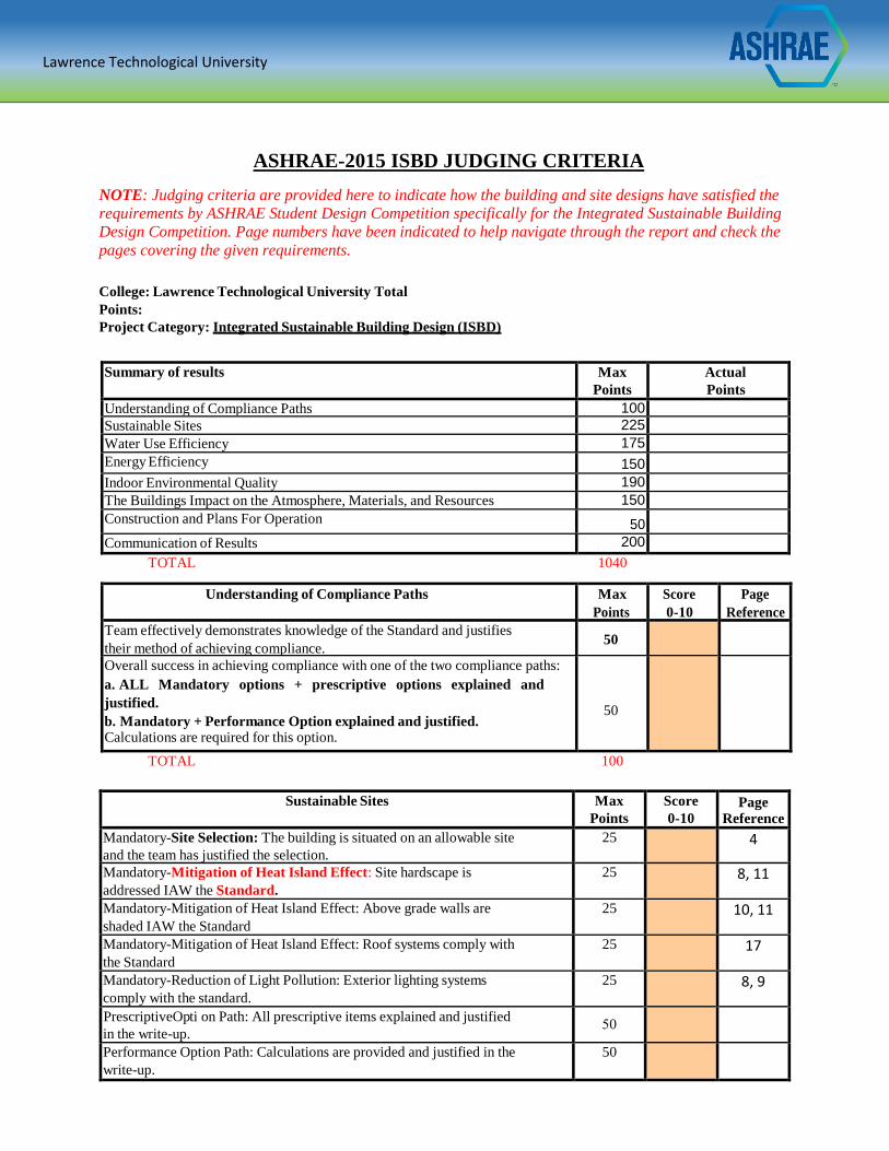
Sustainable Sites Max
Points
Score
0-10 Page
Reference
Mandatory-Site Selection: The building is situated on an allowable site
and the team has justified the selection.
25 4
Mandatory-Mitigation of Heat Island Effect: Site hardscape is
addressed IAW the Standard.
25 8, 11
Mandatory-Mitigation of Heat Island Effect: Above grade walls are
shaded IAW the Standard
25 10, 11
Mandatory-Mitigation of Heat Island Effect: Roof systems comply with
the Standard
25 17
Mandatory-Reduction of Light Pollution: Exterior lighting systems
comply with the standard.
25 8, 9
PrescriptiveOp ti on Path: All prescriptive items explained and justified
in the write-up. 50
Performance Option Path: Calculations are provided and justified in the
write-up.
50
ASHRAE-2015 ISBD JUDGING CRITERIA
NOTE: Judging criteria are provided here to indicate how the building and site designs have satisfied the
requirements by ASHRAE Student Design Competition specifically for the Integrated Sustainable Building
Design Competition. Page numbers have been indicated to help navigate through the report and check the
pages covering the given requirements.
College: Lawrence Technological University Total
Points:
Project Category: Integrated Sustainable Building Design (ISBD)
Summary of results Max
Points
Actual
Points
Understanding of Compliance Paths 100
Sustainable Sites 225
Water Use Efficiency 175
Energy Efficiency 150
Indoor Environmental Quality 190
The Buildings Impact on the Atmosphere, Materials, and Resources 150
Construction and Plans For Operation 50
Communication of Results 200
TOTAL 1040
Understanding of Compliance Paths Max
Points
Score
0-10
Page
Reference
Team effectively demonstrates knowledge of the Standard and justifies
their method of achieving compliance. 50
Overall success in achieving compliance with one of the two compliance paths:
a. ALL Mandatory options + prescriptive options explained and
justified.
b. Mandatory + Performance Option explained and justified.Calculations are required for this option.
50
TOTAL 100
Lawrence Technological University
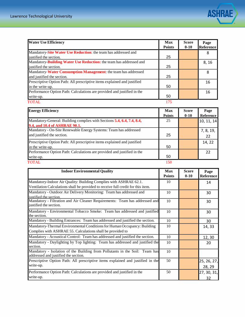
Water Use Efficiency Max
Points
Score
0-10 Page
Reference
Mandatory-Site Water Use Reduction: the team has addressed and
justified the section.
25
8
Mandatory-Building Water Use Reduction: the team has addressed and
justified the section.
25
8, 16
Mandatory-Water Consumption Management: the team has addressed
and justified the section.
25
8
Prescriptive Option Path: All prescriptive items explained and justified
in the write-up.
50
16
16 Performance Option Path: Calculations are provided and justified in the
write-up.
50
16
TOTAL 175
Energy Efficiency Max
Points
Score
0-10
Page
Reference
Mandatory-General: Building complies with Sections 5.4, 6.4, 7.4, 8.4,
9.4, and 10.4 of ASHRAE 90.1.
25 10, 11, 14
Mandatory - On-Site Renewable Energy Systems: Team has addressed
and justified the section.
25
7, 8, 19,
22
Prescriptive Option Path: All prescriptive items explained and justified
in the write-up.
50
14, 22
Performance Option Path: Calculations are provided and justified in the
write-up.
50
22
TOTAL 150
Indoor Environmental Quality Max
Points
Score
0-10 Page
Reference
Mandatory-Indoor Air Quality: Building Complies with ASHRAE 62.1.
Ventilation Calculations shall be provided to receive full credit for this item.
10 14
Mandatory - Outdoor Air Delivery Monitoring: Team has addressed and
justified the section.
10 30
Mandatory - Filtration and Air Cleaner Requirements: Team has addressed and justified the section.
10 30
Mandatory - Environmental Tobacco Smoke: Team has addressed and justified the section.
10 30
Mandatory - Building Entrances: Team has addressed and justified the section. 10 30 Mandatory-Thermal Environmental Conditions for Human Occupancy: Building
Complies with ASHRAE 55. Calculations shall be provided to
receive full credit for this item.
10 14, 33
Mandatory - Acoustical Control: Team has addressed and justified the section. 10 12, 30 Mandatory - Daylighting by Top lighting: Team has addressed and justified the section.
10 20
Mandatory - Isolation of the Building from Pollutants in the Soil: Team has addressed and justified the section.
10
Prescriptive Option Path: All prescriptive items explained and justified in the
write-up.
50 25, 26, 27,
28, 29 Performance Option Path: Calculations are provided and justified in the
write-up.
50 27, 30, 31,
32
Lawrence Technological University
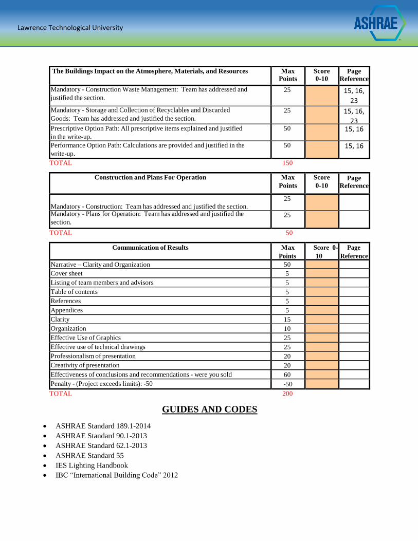
The Buildings Impact on the Atmosphere, Materials, and Resources Max Points
Score 0-10
Page
Reference
Mandatory - Construction Waste Management: Team has addressed and
justified the section.
25 15, 16,
23 Mandatory - Storage and Collection of Recyclables and Discarded
Goods: Team has addressed and justified the section.
25 15, 16,
23 Prescriptive Option Path: All prescriptive items explained and justified
in the write-up.
50 15, 16
Performance Option Path: Calculations are provided and justified in the
write-up.
50 15, 16
TOTAL 150
Construction and Plans For Operation Max
Points
Score
0-10 Page
Reference
Mandatory - Construction: Team has addressed and justified the section.
25
Mandatory - Plans for Operation: Team has addressed and justified the
section. 25
TOTAL 50
Communication of Results Max
Points
Score 0-
10
Page
Reference
Narrative – Clarity and Organization 50 Cover sheet 5 Listing of team members and advisors 5 Table of contents 5 References 5 Appendices 5 Clarity 15 Organization 10 Effective Use of Graphics 25 Effective use of technical drawings 25 Professionalism of presentation 20 Creativity of presentation 20 Effectiveness of conclusions and recommendations - were you sold 60 Penalty - (Project exceeds limits): -50 -50
TOTAL 200
GUIDES AND CODES
ASHRAE Standard 189.1-2014
ASHRAE Standard 90.1-2013
ASHRAE Standard 62.1-2013
ASHRAE Standard 55
IES Lighting Handbook
IBC “International Building Code” 2012
Lawrence Technological University
1 Integrated Sustainable Building Design – ASHRAE 2015
INTRODUCTION
Sustainability has been considered the lead approach in every design and construction
process to achieve buildings that have the least environmental impacts, energy consumption, and
carbon foot-print. Therefore, ASHRAE design standards have been utilized extensively as a
guideline throughout the design process to improve the overall building performance. The Training
Technology Center has been designed and developed to set an example of a sustainable and high
energy performance building. The educational building consumes as minimum energy as possible
during a whole year of heating, cooling, ventilation, and lighting and it responds well to the climatic
conditions -hot and humid- of Doha, Qatar where it is assumed to be located. The Education City
has been selected as a potential site for the educational building. This particular district has been
developed to seek Qatar’s vision to use sustainable technology and material, leading to an
environmentally responsive and contemporary architecture while preserving Qatar’s culture and
Arab identity. Sustainable approaches have been utilized to design both the site and building. The
site has been studied to promote the connectivity of the educational building to the other existing
buildings on site. Also, a parking area was introduced to the site integrated with systems that increase
the use of renewable energy resources and energy production which in return optimizes the energy
performance at community level.
Lawrence Technological University
2 Integrated Sustainable Building Design – ASHRAE 2015
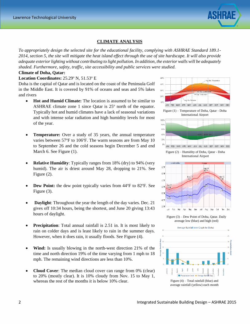
CLIMATE ANALYSIS
To appropriately design the selected site for the educational facility, complying with ASHRAE Standard 189.1-
2014, section 5, the site will mitigate the heat island effect through the use of site hardscape. It will also provide
adequate exterior lighting without contributing to light pollution. In addition, the exterior walls will be adequately
shaded. Furthermore, safety, traffic, site accessibility and public services were studied.
Climate of Doha, Qatar:
Location Coordinates: 25.29o N, 51.53o E
Doha is the capital of Qatar and is located on the coast of the Peninsula Golf
in the Middle East. It is covered by 91% of oceans and seas and 5% lakes
and rivers
Hot and Humid Climate: The location is assumed to be similar to
ASHRAE climate zone 1 since Qatar is 25o north of the equator.
Typically hot and humid climates have a lack of seasonal variations
and with intense solar radiation and high humidity levels for most
of the year.
Temperature: Over a study of 35 years, the annual temperature
varies between 57oF to 106oF. The warm seasons are from May 10
to September 26 and the cold seasons begin December 5 and end
March 6. See Figure (1).
Relative Humidity: Typically ranges from 18% (dry) to 94% (very
humid). The air is driest around May 28, dropping to 21%. See
Figure (2).
Dew Point: the dew point typically varies from 44oF to 82oF. See
Figure (3).
Daylight: Throughout the year the length of the day varies. Dec. 21
gives off 10:34 hours, being the shortest, and June 20 giving 13:43
hours of daylight.
Precipitation: Total annual rainfall is 2.51 in. It is most likely to
rain on colder days and is least likely to rain in the summer days.
However, when it does rain, it usually floods. See Figure (4).
Wind: Is usually blowing in the north-west direction 21% of the
time and north direction 19% of the time varying from 1 mph to 18
mph. The remaining wind directions are less than 10%.
Cloud Cover: The median cloud cover can range from 0% (clear)
to 20% (mostly clear). It is 10% cloudy from Nov. 15 to May 1,
whereas the rest of the months it is below 10% clear.
Figure (1) – Temperature of Doha, Qatar - Doha
International Airport
Figure (2) – Humidity of Doha, Qatar - Doha
International Airport
Figure (3) – Dew Point of Doha, Qatar. Daily
average low (blue) and high (red)
Figure (4) – Total rainfall (blue) and
average rainfall (yellow) each month
Lawrence Technological University
3 Integrated Sustainable Building Design – ASHRAE 2015
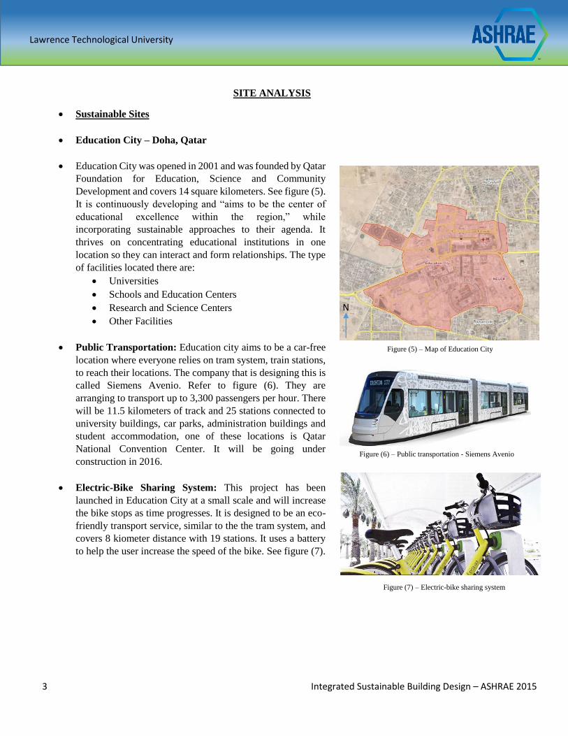
SITE ANALYSIS
Sustainable Sites
Education City – Doha, Qatar
Education City was opened in 2001 and was founded by Qatar
Foundation for Education, Science and Community
Development and covers 14 square kilometers. See figure (5).
It is continuously developing and “aims to be the center of
educational excellence within the region,” while
incorporating sustainable approaches to their agenda. It
thrives on concentrating educational institutions in one
location so they can interact and form relationships. The type
of facilities located there are:
Universities
Schools and Education Centers
Research and Science Centers
Other Facilities
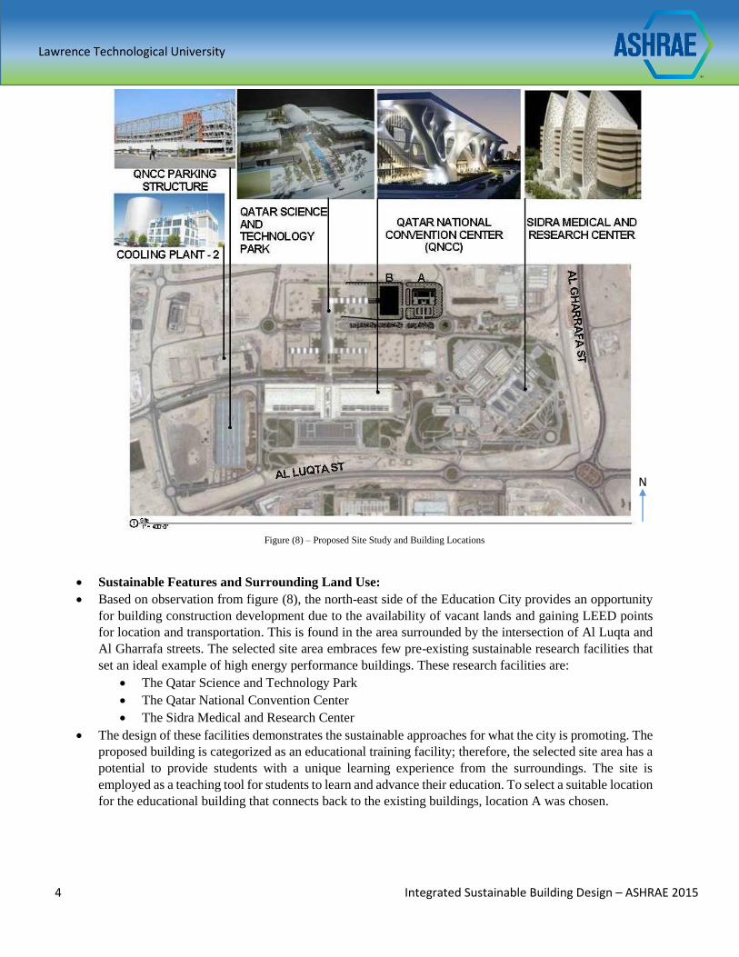
Public Transportation: Education city aims to be a car-free
location where everyone relies on tram system, train stations,
to reach their locations. The company that is designing this is
called Siemens Avenio. Refer to figure (6). They are
arranging to transport up to 3,300 passengers per hour. There
will be 11.5 kilometers of track and 25 stations connected to
university buildings, car parks, administration buildings and
student accommodation, one of these locations is Qatar
National Convention Center. It will be going under
construction in 2016.
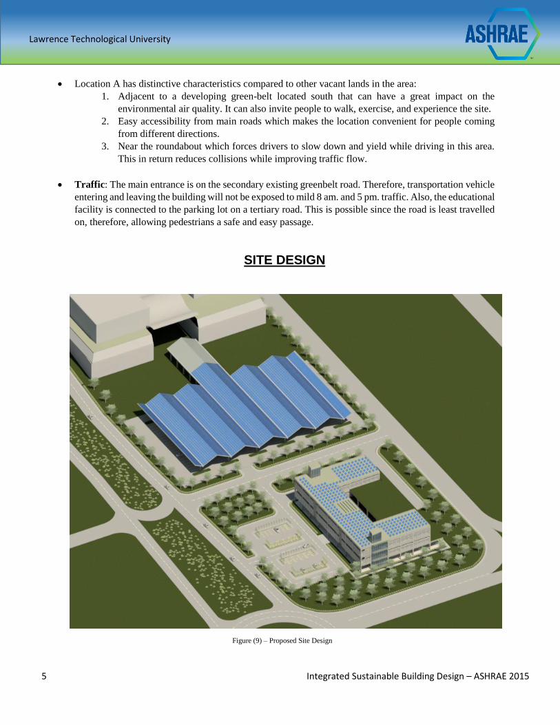
Electric-Bike Sharing System: This project has been
launched in Education City at a small scale and will increase
the bike stops as time progresses. It is designed to be an eco-
friendly transport service, similar to the the tram system, and
covers 8 kiometer distance with 19 stations. It uses a battery
to help the user increase the speed of the bike. See figure (7).
Figure (5) – Map of Education City
Figure (6) – Public transportation - Siemens Avenio
Figure (7) – Electric-bike sharing system
N
Lawrence Technological University
4 Integrated Sustainable Building Design – ASHRAE 2015
Sustainable Features and Surrounding Land Use:
Based on observation from figure (8), the north-east side of the Education City provides an opportunity
for building construction development due to the availability of vacant lands and gaining LEED points
for location and transportation. This is found in the area surrounded by the intersection of Al Luqta and
Al Gharrafa streets. The selected site area embraces few pre-existing sustainable research facilities that
set an ideal example of high energy performance buildings. These research facilities are:
The Qatar Science and Technology Park
The Qatar National Convention Center
The Sidra Medical and Research Center
The design of these facilities demonstrates the sustainable approaches for what the city is promoting. The
proposed building is categorized as an educational training facility; therefore, the selected site area has a
potential to provide students with a unique learning experience from the surroundings. The site is
employed as a teaching tool for students to learn and advance their education. To select a suitable location
for the educational building that connects back to the existing buildings, location A was chosen.
Figure (8) – Proposed Site Study and Building Locations
N
Lawrence Technological University
5 Integrated Sustainable Building Design – ASHRAE 2015
Location A has distinctive characteristics compared to other vacant lands in the area:
1. Adjacent to a developing green-belt located south that can have a great impact on the
environmental air quality. It can also invite people to walk, exercise, and experience the site.
2. Easy accessibility from main roads which makes the location convenient for people coming
from different directions.
3. Near the roundabout which forces drivers to slow down and yield while driving in this area.
This in return reduces collisions while improving traffic flow.
Traffic: The main entrance is on the secondary existing greenbelt road. Therefore, transportation vehicle
entering and leaving the building will not be exposed to mild 8 am. and 5 pm. traffic. Also, the educational
facility is connected to the parking lot on a tertiary road. This is possible since the road is least travelled
on, therefore, allowing pedestrians a safe and easy passage.
SITE DESIGN
Figure (9) – Proposed Site Design
Lawrence Technological University
6 Integrated Sustainable Building Design – ASHRAE 2015
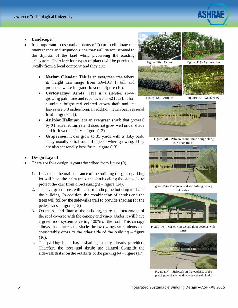
Landscape:
It is important to use native plants of Qatar to eliminate the
maintenance and irrigation since they will be accustomed to
the dryness of the land while preserving the existing
ecosystem. Therefore four types of plants will be purchased
locally from a local company and they are:
Nerium Olender: This is an evergreen tree where
its height can range from 6.6-19.7 ft tall and
produces white fragrant flowers – figure (10).
Cyrtostachys Renda: This is a slender, slow-
growing palm tree and reaches up to 52 ft tall. It has
a unique bright red colored crown-shaft and its
leaves are 5.9 inches long. In addition, it can bear seasonal
fruit – figure (11).
Atriplex Halimus: it is an evergreen shrub that grows 6
by 9 ft at a medium rate. It does not grow well under shade
and it flowers in July – figure (12).
Grapevines: it can grow to 35 yards with a flaky bark.
They usually spiral around objects when growing. They
are also seasonally bear fruit – figure (13).
Design Layout:
There are four design layouts described from figure (9).
1. Located at the main entrance of the building the guest parking
lot will have the palm trees and shrubs along the sidewalk to
protect the cars from direct sunlight – figure (14).
2. The evergreen trees will be surrounding the building to shade
the building. In addition, the combination of shrubs and the
trees will follow the sidewalks trail to provide shading for the
pedestrians – figure (15).
3. On the second floor of the building, there is a percentage of
the roof covered with the canopy and vines. Under it will have
a green roof system covering 100% of the roof. This canopy
allows to connect and shade the two wings so students can
comfortably cross to the other side of the building – figure
(16).
4. The parking lot is has a shading canopy already provided.
Therefore the trees and shrubs are planted alongside the
sidewalk that is on the outskirts of the parking lot – figure (17).
Figure (10) – Nerium
Olender Figure (11) – Cyrtostachys
Renda Halimus
Figure (12) – Atriplex
Halimus Figure (13) – Grapevines
Figure (15) – Evergreen and shrub design along
sidewalks
Figure (14) – Palm trees and shrub design along
guest parking lot
Figure (16) – Canopy on second floor covered with
vines
Figure (17) – Sidewalk on the outskirts of the
parking lot shaded with evergreen and shrubs
Lawrence Technological University
7 Integrated Sustainable Building Design – ASHRAE 2015
Design Approach: for a hot and humid climate, the landscape must be strategically designed to mitigate
the heat island effect for a low rise building. This will help to control:
1. Radiation
2. Heat
3. Wind
Radiation: The landscape elements that are selected will help to deflect and diffuse the light since the
leaves will be blocking the direct sunlight and increase the area of shading. This will help mitigate the
heat island effect, therefore cooling loads for the mechanical equipment in the educational facility will
be reduced.
Heat: Shading a large percentage of the surface from direct sunlight will help to cool the shaded surface
and air temperature by 20 - 45oF compared to unshaded surfaces. This will help to reduce the urban heat
island. This also contributes to minimizing glare reflecting from surfaces that are not shaded.
Wind: The wind is dominant on the north and north-west direction. Because this is a hot climate,
staggering the trees on the north side of the building will help the wind be “funneled” to create a cool
breeze for the outdoor spaces of the building. The wind can also pick up the dust particles creating a dust
storm, however, the density of leaves on the evergreens will able to collect the dust and minimizes it as
it reaches the building.
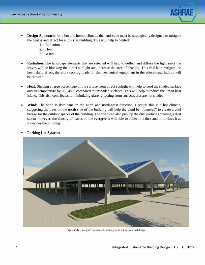
Parking Lot System:
Figure (18) – Integrated sustainable parking lot structure proposed design
Lawrence Technological University
8 Integrated Sustainable Building Design – ASHRAE 2015
Parking lot Design: The integrated and sustainable parking lot is
located west of the educational facility. It provides renewable energy,
security and a natural resource management system. The structure is
made of concrete and is constructed using three pieces. Two pieces are
the column and half of the roof canopy and the third piece is the
inverted V shape center piece that connects the other two pieces using
a key connection, seen in figure (19)
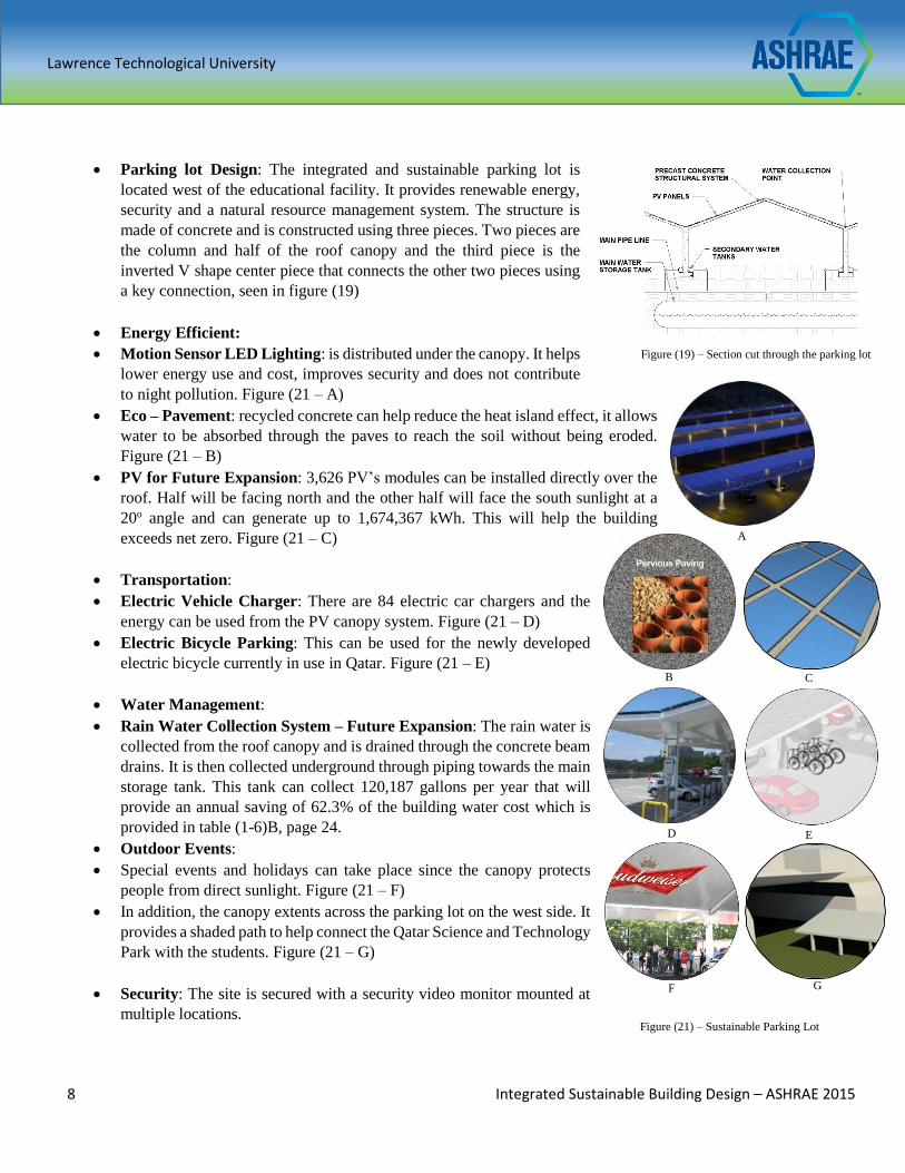
Energy Efficient:
Motion Sensor LED Lighting: is distributed under the canopy. It helps
lower energy use and cost, improves security and does not contribute
to night pollution. Figure (21 – A)
Eco – Pavement: recycled concrete can help reduce the heat island effect, it allows
water to be absorbed through the paves to reach the soil without being eroded.
Figure (21 – B)
PV for Future Expansion: 3,626 PV’s modules can be installed directly over the
roof. Half will be facing north and the other half will face the south sunlight at a
20o angle and can generate up to 1,674,367 kWh. This will help the building
exceeds net zero. Figure (21 – C)
Transportation:
Electric Vehicle Charger: There are 84 electric car chargers and the
energy can be used from the PV canopy system. Figure (21 – D)
Electric Bicycle Parking: This can be used for the newly developed
electric bicycle currently in use in Qatar. Figure (21 – E)
Water Management:
Rain Water Collection System – Future Expansion: The rain water is
collected from the roof canopy and is drained through the concrete beam
drains. It is then collected underground through piping towards the main
storage tank. This tank can collect 120,187 gallons per year that will
provide an annual saving of 62.3% of the building water cost which is
provided in table (1-6)B, page 24.
Outdoor Events:
Special events and holidays can take place since the canopy protects
people from direct sunlight. Figure (21 – F)
In addition, the canopy extents across the parking lot on the west side. It
provides a shaded path to help connect the Qatar Science and Technology
Park with the students. Figure (21 – G)
Security: The site is secured with a security video monitor mounted at
multiple locations.
B
F
C
G
D E
A
Figure (21) – Sustainable Parking Lot
Figure (19) – Section cut through the parking lot
Lawrence Technological University
9 Integrated Sustainable Building Design – ASHRAE 2015
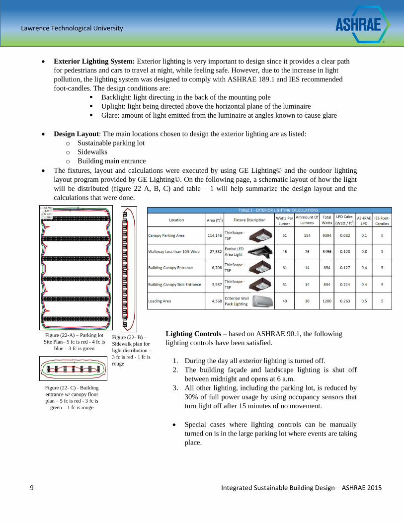
Exterior Lighting System: Exterior lighting is very important to design since it provides a clear path
for pedestrians and cars to travel at night, while feeling safe. However, due to the increase in light
pollution, the lighting system was designed to comply with ASHRAE 189.1 and IES recommended
foot-candles. The design conditions are:
Backlight: light directing in the back of the mounting pole
Uplight: light being directed above the horizontal plane of the luminaire
Glare: amount of light emitted from the luminaire at angles known to cause glare
Design Layout: The main locations chosen to design the exterior lighting are as listed:
o Sustainable parking lot
o Sidewalks
o Building main entrance
The fixtures, layout and calculations were executed by using GE Lighting© and the outdoor lighting
layout program provided by GE Lighting©. On the following page, a schematic layout of how the light
will be distributed (figure 22 A, B, C) and table – 1 will help summarize the design layout and the
calculations that were done.
Lighting Controls – based on ASHRAE 90.1, the following
lighting controls have been satisfied.
1. During the day all exterior lighting is turned off.
2. The building façade and landscape lighting is shut off
between midnight and opens at 6 a.m.
3. All other lighting, including the parking lot, is reduced by
30% of full power usage by using occupancy sensors that
turn light off after 15 minutes of no movement.
Special cases where lighting controls can be manually
turned on is in the large parking lot where events are taking
place.
Figure (22- B) –
Sidewalk plan for
light distribution –
3 fc is red - 1 fc is
rouge
Figure (22-A) – Parking lot
Site Plan– 5 fc is red - 4 fc is
blue – 3 fc is green
Figure (22- C) - Building
entrance w/ canopy floor
plan – 5 fc is red - 3 fc is
green – 1 fc is rouge
Lawrence Technological University
10 Integrated Sustainable Building Design – ASHRAE 2015
BUILDING BIO-CLIMATIC DESIGN STRATEGIES
To achieve a design that best responds to the climatic conditions in Doha, Qatar as well as enhances the primary
function of the educational building, multiple recommended design strategies by Climate Consultant 0.6 software
were considered throughout the phases of the building design development. In addition, some design strategies
that were employed by the great architect Louis Kahn were also applied in the design of this project. These
strategies aid in attaining a more energy efficient building design with the optimum comfort and energy savings
to meet ASHRAE Standard 189.1-2014, section 7, energy efficiency.
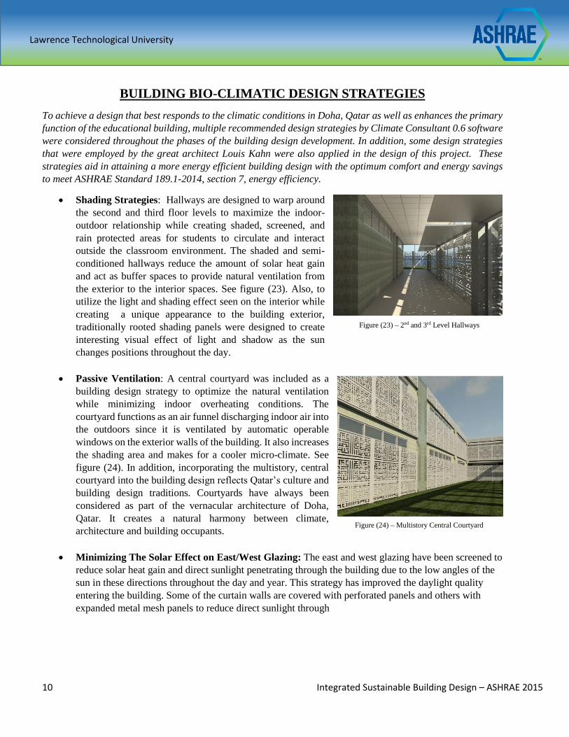
Shading Strategies: Hallways are designed to warp around
the second and third floor levels to maximize the indoor-
outdoor relationship while creating shaded, screened, and
rain protected areas for students to circulate and interact
outside the classroom environment. The shaded and semi-
conditioned hallways reduce the amount of solar heat gain
and act as buffer spaces to provide natural ventilation from
the exterior to the interior spaces. See figure (23). Also, to
utilize the light and shading effect seen on the interior while
creating a unique appearance to the building exterior,
traditionally rooted shading panels were designed to create
interesting visual effect of light and shadow as the sun
changes positions throughout the day.
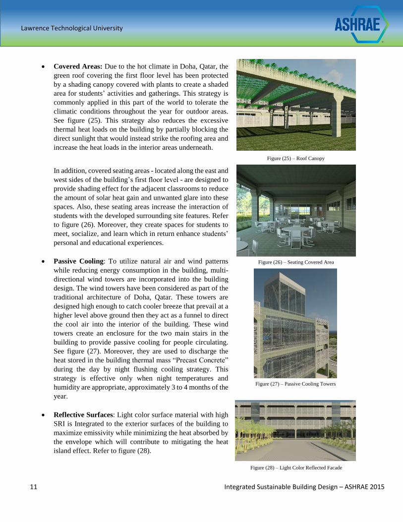
Passive Ventilation: A central courtyard was included as a
building design strategy to optimize the natural ventilation
while minimizing indoor overheating conditions. The
courtyard functions as an air funnel discharging indoor air into
the outdoors since it is ventilated by automatic operable
windows on the exterior walls of the building. It also increases
the shading area and makes for a cooler micro-climate. See
figure (24). In addition, incorporating the multistory, central
courtyard into the building design reflects Qatar’s culture and
building design traditions. Courtyards have always been
considered as part of the vernacular architecture of Doha,
Qatar. It creates a natural harmony between climate,
architecture and building occupants.
Minimizing The Solar Effect on East/West Glazing: The east and west glazing have been screened to
reduce solar heat gain and direct sunlight penetrating through the building due to the low angles of the
sun in these directions throughout the day and year. This strategy has improved the daylight quality
entering the building. Some of the curtain walls are covered with perforated panels and others with
expanded metal mesh panels to reduce direct sunlight through
Figure (23) – 2nd and 3rd Level Hallways
Figure (24) – Multistory Central Courtyard
Lawrence Technological University
11 Integrated Sustainable Building Design – ASHRAE 2015
Covered Areas: Due to the hot climate in Doha, Qatar, the
green roof covering the first floor level has been protected
by a shading canopy covered with plants to create a shaded
area for students’ activities and gatherings. This strategy is
commonly applied in this part of the world to tolerate the
climatic conditions throughout the year for outdoor areas.
See figure (25). This strategy also reduces the excessive
thermal heat loads on the building by partially blocking the
direct sunlight that would instead strike the roofing area and
increase the heat loads in the interior areas underneath.
In addition, covered seating areas - located along the east and
west sides of the building’s first floor level - are designed to
provide shading effect for the adjacent classrooms to reduce
the amount of solar heat gain and unwanted glare into these
spaces. Also, these seating areas increase the interaction of
students with the developed surrounding site features. Refer
to figure (26). Moreover, they create spaces for students to
meet, socialize, and learn which in return enhance students’
personal and educational experiences.
Passive Cooling: To utilize natural air and wind patterns
while reducing energy consumption in the building, multi-
directional wind towers are incorporated into the building
design. The wind towers have been considered as part of the
traditional architecture of Doha, Qatar. These towers are
designed high enough to catch cooler breeze that prevail at a
higher level above ground then they act as a funnel to direct
the cool air into the interior of the building. These wind
towers create an enclosure for the two main stairs in the
building to provide passive cooling for people circulating.
See figure (27). Moreover, they are used to discharge the
heat stored in the building thermal mass “Precast Concrete”
during the day by night flushing cooling strategy. This
strategy is effective only when night temperatures and
humidity are appropriate, approximately 3 to 4 months of the
year.
Reflective Surfaces: Light color surface material with high
SRI is Integrated to the exterior surfaces of the building to
maximize emissivity while minimizing the heat absorbed by
the envelope which will contribute to mitigating the heat
island effect. Refer to figure (28).
Figure (28) – Light Color Reflected Facade
Figure (25) – Roof Canopy
Figure (26) – Seating Covered Area
Figure (27) – Passive Cooling Towers
Lawrence Technological University
12 Integrated Sustainable Building Design – ASHRAE 2015
Building Program & Spatial Organization
The design and organization of the interior spaces of the educational building is as important as the design of the
exterior facades. Taking that into consideration, studies have been conducted to understand the unique strategies
that were used by the great architect, Louis Kahn. A specific building of his work – The Indian Institute of
Management Building- was studied to learn about the path Louis Kahn took when he designed this educational
building in a climate that is similar to Doha, Qatar in some sense.
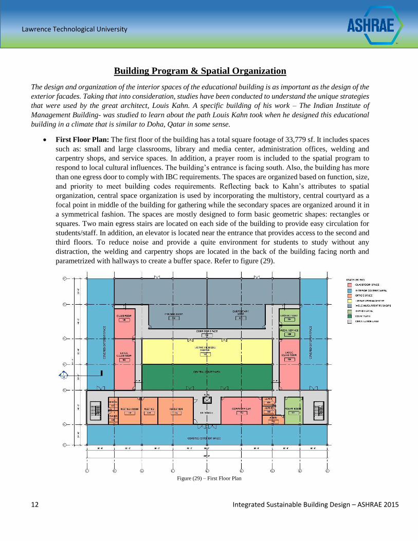
First Floor Plan: The first floor of the building has a total square footage of 33,779 sf. It includes spaces
such as: small and large classrooms, library and media center, administration offices, welding and
carpentry shops, and service spaces. In addition, a prayer room is included to the spatial program to
respond to local cultural influences. The building’s entrance is facing south. Also, the building has more
than one egress door to comply with IBC requirements. The spaces are organized based on function, size,
and priority to meet building codes requirements. Reflecting back to Kahn’s attributes to spatial
organization, central space organization is used by incorporating the multistory, central courtyard as a
focal point in middle of the building for gathering while the secondary spaces are organized around it in
a symmetrical fashion. The spaces are mostly designed to form basic geometric shapes: rectangles or
squares. Two main egress stairs are located on each side of the building to provide easy circulation for
students/staff. In addition, an elevator is located near the entrance that provides access to the second and
third floors. To reduce noise and provide a quite environment for students to study without any
distraction, the welding and carpentry shops are located in the back of the building facing north and
parametrized with hallways to create a buffer space. Refer to figure (29).
Figure (29) – First Floor Plan
Lawrence Technological University
13 Integrated Sustainable Building Design – ASHRAE 2015
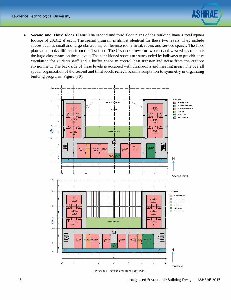
Second and Third Floor Plans: The second and third floor plans of the building have a total square
footage of 29,912 sf each. The spatial program is almost identical for these two levels. They include
spaces such as small and large classrooms, conference room, break room, and service spaces. The floor
plan shape looks different from the first floor. The U-shape allows for two east and west wings to house
the large classrooms on these levels. The conditioned spaces are surrounded by hallways to provide easy
circulation for students/staff and a buffer space to control heat transfer and noise from the outdoor
environment. The back side of these levels is occupied with classrooms and meeting areas. The overall
spatial organization of the second and third levels reflects Kahn’s adaptation to symmetry in organizing
building programs. Figure (30).
Figure (30) – Second and Third Floor Plans
N
N
Second level
Third level
Lawrence Technological University
14 Integrated Sustainable Building Design – ASHRAE 2015
Figure (33) – Precast Concrete Structural System Figure (32) – PC Beam on Column
Corbels
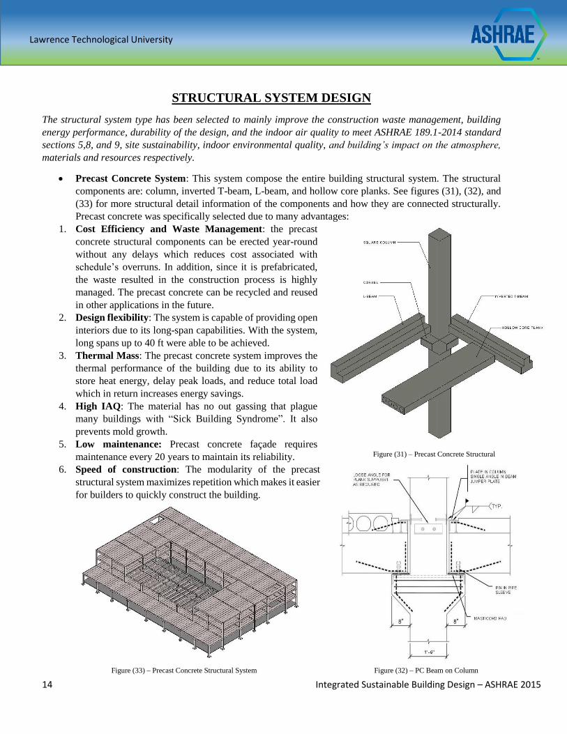
STRUCTURAL SYSTEM DESIGN
The structural system type has been selected to mainly improve the construction waste management, building
energy performance, durability of the design, and the indoor air quality to meet ASHRAE 189.1-2014 standard
sections 5,8, and 9, site sustainability, indoor environmental quality, and building’s impact on the atmosphere,
materials and resources respectively.
Precast Concrete System: This system compose the entire building structural system. The structural
components are: column, inverted T-beam, L-beam, and hollow core planks. See figures (31), (32), and
(33) for more structural detail information of the components and how they are connected structurally.
Precast concrete was specifically selected due to many advantages:
1. Cost Efficiency and Waste Management: the precast
concrete structural components can be erected year-round
without any delays which reduces cost associated with
schedule’s overruns. In addition, since it is prefabricated,
the waste resulted in the construction process is highly
managed. The precast concrete can be recycled and reused
in other applications in the future.
2. Design flexibility: The system is capable of providing open
interiors due to its long-span capabilities. With the system,
long spans up to 40 ft were able to be achieved.
3. Thermal Mass: The precast concrete system improves the
thermal performance of the building due to its ability to
store heat energy, delay peak loads, and reduce total load
which in return increases energy savings.
4. High IAQ: The material has no out gassing that plague
many buildings with “Sick Building Syndrome”. It also
prevents mold growth.
5. Low maintenance: Precast concrete façade requires
maintenance every 20 years to maintain its reliability.
6. Speed of construction: The modularity of the precast
structural system maximizes repetition which makes it easier
for builders to quickly construct the building.
Figure (31) – Precast Concrete Structural
Components
Lawrence Technological University
15 Integrated Sustainable Building Design – ASHRAE 2015
BIO-CLIMATIC ENVELOPE DESIGN PROPERTIES
In order to increase the energy efficiency performance of the building while reducing the building loads,
energy consumptions, and materials’ environmental impact, the development of the building exterior
envelope was prioritized. Therefore, locally supplied and recycled content materials were selected for the
design to meet the requirements of ASHRAE standard 189.1-2014, section 9. In addition, table E-2 with the
recommended U-values for buildings’ envelope was used per zone 1. In addition, construction waste
management along with storage and collection of recyclable and discarded goods are also considered. The
following is a list of all the materials specified for the exterior envelope of the educational building:
Exterior Walls
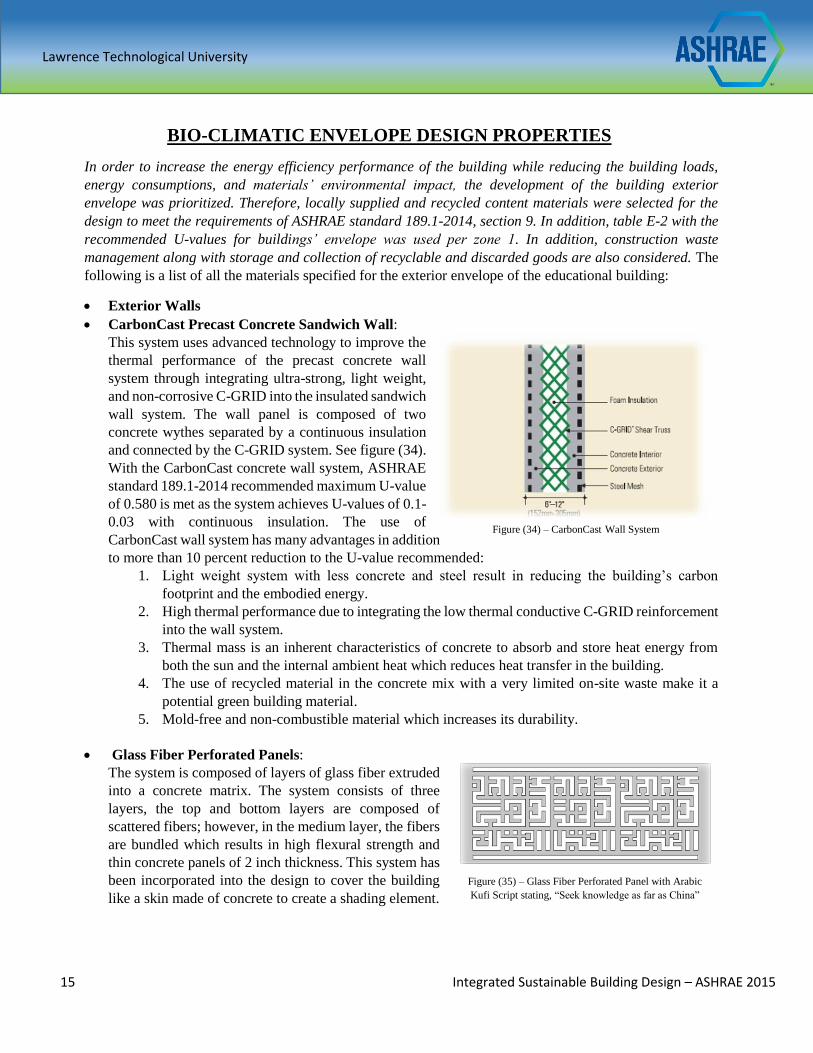
CarbonCast Precast Concrete Sandwich Wall:
This system uses advanced technology to improve the
thermal performance of the precast concrete wall
system through integrating ultra-strong, light weight,
and non-corrosive C-GRID into the insulated sandwich
wall system. The wall panel is composed of two
concrete wythes separated by a continuous insulation
and connected by the C-GRID system. See figure (34).
With the CarbonCast concrete wall system, ASHRAE
standard 189.1-2014 recommended maximum U-value
of 0.580 is met as the system achieves U-values of 0.1-
0.03 with continuous insulation. The use of
CarbonCast wall system has many advantages in addition
to more than 10 percent reduction to the U-value recommended:
1. Light weight system with less concrete and steel result in reducing the building’s carbon
footprint and the embodied energy.
2. High thermal performance due to integrating the low thermal conductive C-GRID reinforcement
into the wall system.
3. Thermal mass is an inherent characteristics of concrete to absorb and store heat energy from
both the sun and the internal ambient heat which reduces heat transfer in the building.
4. The use of recycled material in the concrete mix with a very limited on-site waste make it a
potential green building material.
5. Mold-free and non-combustible material which increases its durability.
Glass Fiber Perforated Panels:
The system is composed of layers of glass fiber extruded
into a concrete matrix. The system consists of three
layers, the top and bottom layers are composed of
scattered fibers; however, in the medium layer, the fibers
are bundled which results in high flexural strength and
thin concrete panels of 2 inch thickness. This system has
been incorporated into the design to cover the building
like a skin made of concrete to create a shading element.
Figure (34) – CarbonCast Wall System
Figure (35) – Glass Fiber Perforated Panel with Arabic
Kufi Script stating, “Seek knowledge as far as China”
Lawrence Technological University
16 Integrated Sustainable Building Design – ASHRAE 2015
These panels are costumed design, incorporating one of the oldest calligraphic Arabic script styles to
reflect the Arabic deep-rooted culture in Doha, Qatar. The script promotes a popular traditional statement
in the Middle East about education, “Seek knowledge as far as China”. See figure (35). The flexibility of
the selected material helps to achieve the artistic Arabic patterns which in return play a major role in
creating a unique building exterior as well as guaranteeing a cathartic experience for people indoor.
The glass fiber panels are considered a green building material due to the following:
1. The product is mainly made of mineral components. 95% of its components are sand, cement,
and glass fibers.
2. Problem-free waste disposal.
3. Environmentally friendly, no contribution to increasing the greenhouse gasses.
4. Cost effective, and fully recyclable.
5. Shading device to reduce solar heat gain.
Expanded Metal Mesh: Along with the perforated panels to
cover the exterior of the building, diamond patterned expanded
metal mesh is incorporated to complete the outer skin of the
building. It is used as a solar screening device to reduce solar
heat gain and glare which makes it contribute to the energy
efficiency of the building. It also helps on improving the indoor
environmental quality by creating a connection between the
indoor spaces and outdoors through the introduction of daylight
and views. In addition, metal mesh is primarily produced from
steel and recyclable materials, therefore, the construction waste
generated can be included in the waste management plan.
Figure (36).
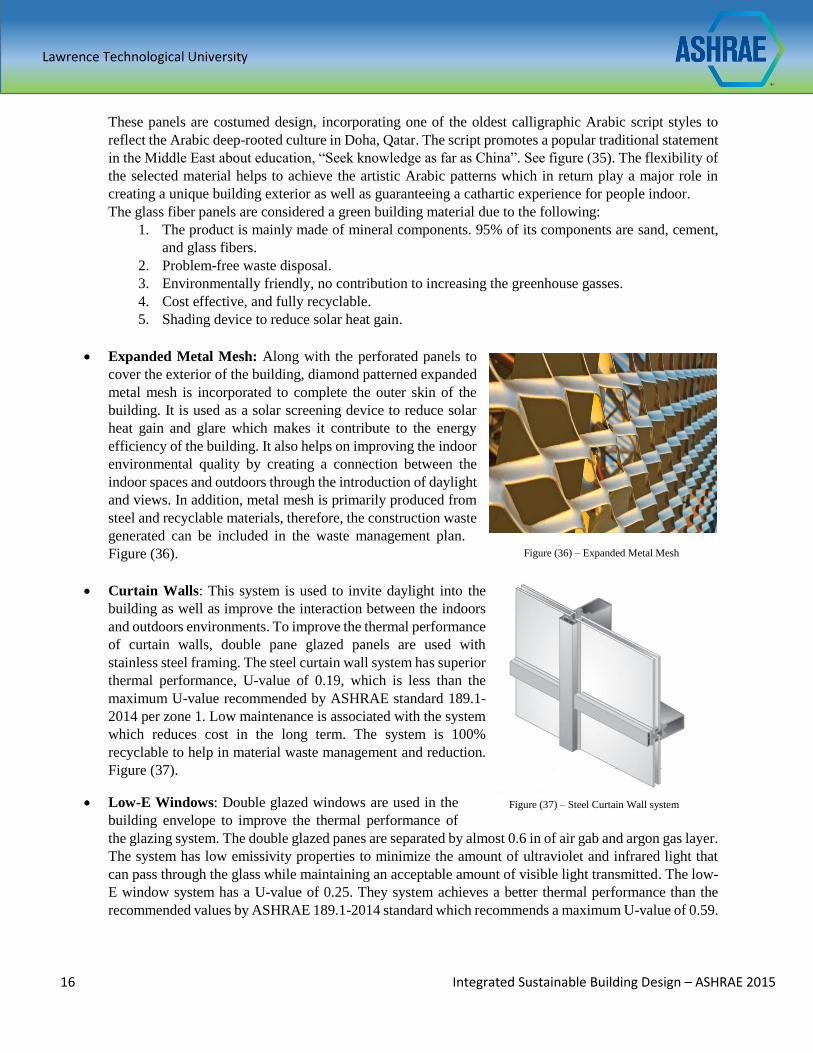
Curtain Walls: This system is used to invite daylight into the
building as well as improve the interaction between the indoors
and outdoors environments. To improve the thermal performance
of curtain walls, double pane glazed panels are used with
stainless steel framing. The steel curtain wall system has superior
thermal performance, U-value of 0.19, which is less than the
maximum U-value recommended by ASHRAE standard 189.1-
2014 per zone 1. Low maintenance is associated with the system
which reduces cost in the long term. The system is 100%
recyclable to help in material waste management and reduction.
Figure (37).
Low-E Windows: Double glazed windows are used in the
building envelope to improve the thermal performance of
the glazing system. The double glazed panes are separated by almost 0.6 in of air gab and argon gas layer.
The system has low emissivity properties to minimize the amount of ultraviolet and infrared light that
can pass through the glass while maintaining an acceptable amount of visible light transmitted. The low-
E window system has a U-value of 0.25. They system achieves a better thermal performance than the
recommended values by ASHRAE 189.1-2014 standard which recommends a maximum U-value of 0.59.
Figure (37) – Steel Curtain Wall system
Figure (36) – Expanded Metal Mesh
Lawrence Technological University
17 Integrated Sustainable Building Design – ASHRAE 2015
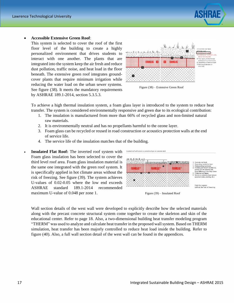
Accessible Extensive Green Roof:
This system is selected to cover the roof of the first
floor level of the building to create a highly
personalized environment that drives students to
interact with one another. The plants that are
integrated into the system keep the air fresh and reduce
dust pollution, traffic noise, and heat load in the floor
beneath. The extensive green roof integrates ground-
cover plants that require minimum irrigation while
reducing the water load on the urban sewer systems.
See figure (38). It meets the mandatory requirements
by ASHRAE 189.1-2014, section 5.3.5.3.
To achieve a high thermal insulation system, a foam glass layer is introduced to the system to reduce heat
transfer. The system is considered environmentally responsive and green due to its ecological contribution:
1. The insulation is manufactured from more than 66% of recycled glass and non-limited natural
raw materials.
2. It is environmentally neutral and has no propellants harmful to the ozone layer.
3. Foam glass can be recycled or reused in road construction or acoustics protection walls at the end
of service life.
4. The service life of the insulation matches that of the building.
Insulated Flat Roof: The inverted roof system with
Foam glass insulation has been selected to cover the
third level roof area. Foam glass insulation material is
the same one integrated with the green roof system. It
is specifically applied in hot climate areas without the
risk of freezing. See figure (39). The system achieves
U-values of 0.02-0.05 where the low end exceeds
ASHRAE standard 189.1-2014 recommended
maximum U-value of 0.048 per zone 1.
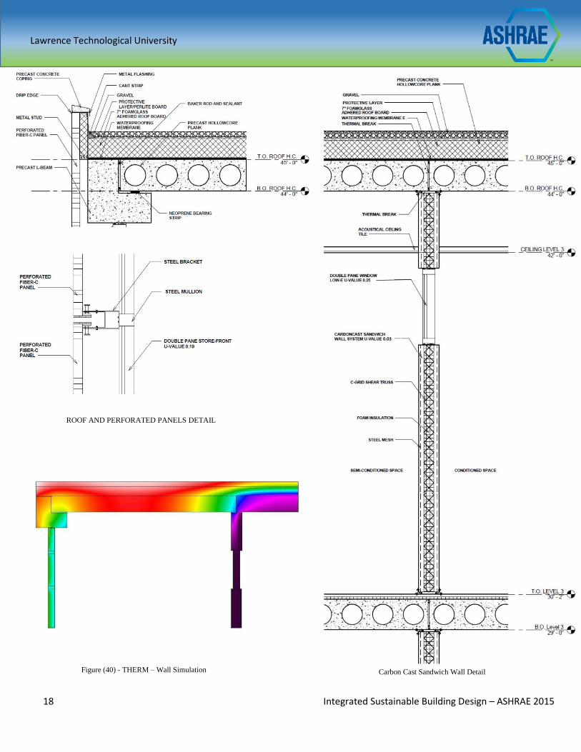
Wall section details of the west wall were developed to explicitly describe how the selected materials
along with the precast concrete structural system come together to create the skeleton and skin of the
educational center. Refer to page 18. Also, a two-dimensional building heat transfer modeling program
“THERM” was used to analyze and calculate heat transfer in the proposed wall system. Based on THERM
simulation, heat transfer has been majorly controlled to reduce heat load inside the building. Refer to
figure (40). Also, a full wall section detail of the west wall can be found in the appendices.
Figure (38) – Extensive Green Roof
Figure (39) – Insulated Roof
Lawrence Technological University
18 Integrated Sustainable Building Design – ASHRAE 2015
ROOF AND PERFORATED PANELS DETAIL
Figure (40) - THERM – Wall Simulation Carbon Cast Sandwich Wall Detail
0.03
Lawrence Technological University
19 Integrated Sustainable Building Design – ASHRAE 2015
LIGHTING SYSTEM DESIGN
Both daylighting and electrical lighting have been considered to provide adequate illumination in the spaces
based on their types and functions. The lighting system has been designed to maximize the use of daylighting
while minimizing the dependence on electrical lighting to reduce electrical energy consumption. The
proposed design meets the requirements recommended by ASHRAE standard 189.1-2014 and ASHRAE
standard 90.1 – 2013 to achieve a more energy efficient lighting design.
Daylighting
The orientation of the building played a major role in determining the amount and quality of daylight
coming into the educational building throughout the day and year. The north façade of the building
receives diffused light which in return reduces solar heat gain. The south façade is shaded with the
perforated panels to allow the admission of low-angle winter sunlight for day lighting and avoid the
higher angle solar radiation in the summer time. Both the east and west facades are shaded with deep
hallways covered with perforated panels to minimize solar heat gain and glare due to sun low-angle.
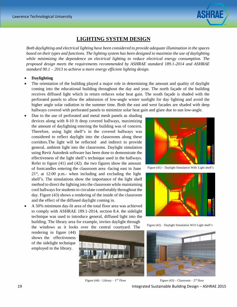
Due to the use of perforated and metal mesh panels as shading
devices along with 8-10 ft deep covered hallways, maximizing
the amount of daylighting entering the building was of concern.
Therefore, using light shelf’s in the covered hallways was
considered to reflect daylight into the classrooms along these
corridors.The light will be reflected and indirect to provide
general, ambient light into the classrooms. Daylight simulation
using Revit Autodesk software has been done to demonstrate the
effectiveness of the light shelf’s technique used in the hallways.
Refer to figure (41) and (42). the two figures show the amount
of footcandles entering the classroom area -facing east in June
21st, at 12:00 p.m.- when including and excluding the light
shelf’s. The simulations show the importance of the light shelf
method to direct the lighting into the classroom while maintaining
cool hallways for students to circulate comfortably throughout the
day. Figure (43) shows a rendering of the inside of the classroom
and the effect of the diffused daylight coming in.
A 50% minimum day-lit area of the total floor area was achieved
to comply with ASHRAE 189.1-2014, section 8.4. the sidelight
technique was used to introduce general, diffused light into the
building. The library area for example, invites daylight through
the windows as it looks over the central courtyard. The
rendering in figure (44)
shows the effectiveness of the sidelight technique
employed in the library.
Figure (44) – Library – 1ST Floor Figure (43) – Classroom – 2nd floor
Figure (42) – Daylight Simulation W/O Light shelf’s
Figure (41) – Daylight Simulation With Light shelf’s
Lawrence Technological University
20 Integrated Sustainable Building Design – ASHRAE 2015
FiberOptics Daylighting Technology: Due to the building form
which makes it an internal load dominated structure as well as the
high degree of solar shading required, daylighting was mainly
considered to reach the interior spaces; therefore, fiber optics
technology was introduced to the project in order to increase the
amount of daylight being received. The solar receivers are mounted
on the roof. These receivers are capable of tracking sunlight
throughout the day to capture sunlight. Optical fibers then transfer
the sunlight through thin and flexible cables with optimized light
transmission. These cables can run up to 200 ft See figure (45).
The use of this technology has some advantages:
1. Heat energy in the solar radiation is primary blocked by the
system which reduces heat gain and heat loads on the
HVAC system in return.
2. No need to create openings in the roof to bring daylight
into the interior space. The openings can affect the
thermal performance of the building. However, fiber
optic cables can run through walls and structure without
any negative impact on the building overall thermal
performance.
3. The system allows for a great integration between
electric lighting and daylighting.
FiberOptics Daylight and Electric Light Integration:
To accomplish a good integration between electric light and
daylighting, the hybrid luminaries are used. These luminaries
combine sunlight with energy efficient LED lighting. When sun
does not provide enough light, the electric LED lights activate to
provide the required light levels in the interior spaces, meaning the
system has embedded photo sensor to control light. Refer to figure
(46).
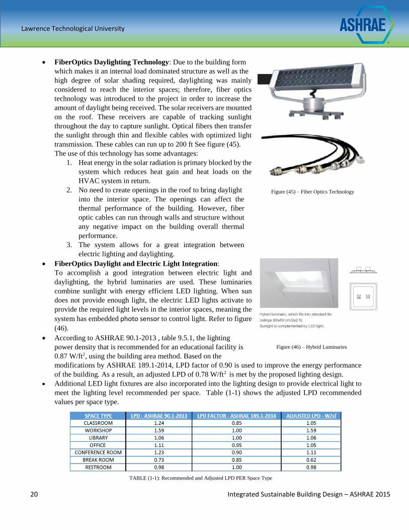
According to ASHRAE 90.1-2013 , table 9.5.1, the lighting
power density that is recommended for an educational facility is
0.87 W/ft2, using the building area method. Based on the
modifications by ASHRAE 189.1-2014, LPD factor of 0.90 is used to improve the energy performance
of the building. As a result, an adjusted LPD of 0.78 W/ft2 is met by the proposed lighting design.
Additional LED light fixtures are also incorporated into the lighting design to provide electrical light to
meet the lighting level recommended per space. Table (1-1) shows the adjusted LPD recommended
values per space type.
TABLE (1-1): Recommended and Adjusted LPD PER Space Type
Figure (45) – Fiber Optics Technology
Figure (46) – Hybrid Luminaries
Lawrence Technological University
21 Integrated Sustainable Building Design – ASHRAE 2015
Different LED luminaries were selected and used in spaces to meet their types and functions see figure
(47) and (48). LED fixtures are used due to the following:
1. Energy savings with LED lighting up to 50-70%.
2. Up to 50,000 hours which significantly reduces maintenance cost.
3. Reduce carbon footprint when coupled with controls.
4. LED’s are considered low heat producing lights which help in reducing cooling loads.
Figure (47) – Conference & Library Fixture Figure (48) – All Other Spaces Fixture
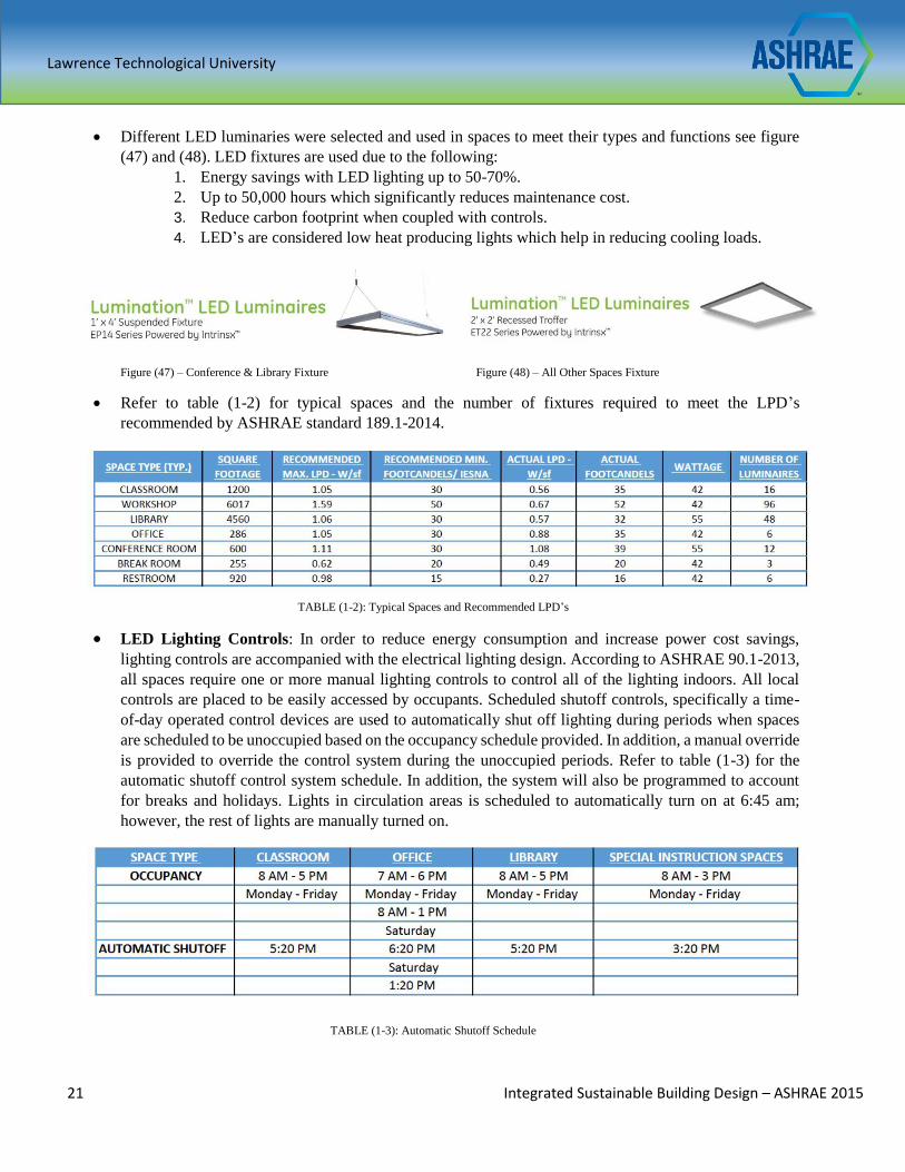
Refer to table (1-2) for typical spaces and the number of fixtures required to meet the LPD’s
recommended by ASHRAE standard 189.1-2014.
TABLE (1-2): Typical Spaces and Recommended LPD’s
LED Lighting Controls: In order to reduce energy consumption and increase power cost savings,
lighting controls are accompanied with the electrical lighting design. According to ASHRAE 90.1-2013,
all spaces require one or more manual lighting controls to control all of the lighting indoors. All local
controls are placed to be easily accessed by occupants. Scheduled shutoff controls, specifically a time-
of-day operated control devices are used to automatically shut off lighting during periods when spaces
are scheduled to be unoccupied based on the occupancy schedule provided. In addition, a manual override
is provided to override the control system during the unoccupied periods. Refer to table (1-3) for the
automatic shutoff control system schedule. In addition, the system will also be programmed to account
for breaks and holidays. Lights in circulation areas is scheduled to automatically turn on at 6:45 am;
however, the rest of lights are manually turned on.
TABLE (1-3): Automatic Shutoff Schedule
Lawrence Technological University
22 Integrated Sustainable Building Design – ASHRAE 2015
PHOTOVOLTAIC SYSTEM DESIGN
In the interest of introducing an on-site renewable energy system to increase the energy efficiency of the building,
photovoltaic system has been designed to convert the renewable and clean solar energy into electricity. To comply with
ASHRAE 189.1-2014, section 5, more than 75% of the roof surface was utilized to house the PV system.
Photovoltaic System: A local donor will provide funding for the installation of a photovoltaic array that
supports 5% of the total building energy needs. However, the PV array was designed to support an additional
11% of the building power demand. The PV panels are provided and distributed by a local manufacturer to
reduce cost associated with shipping. The PV module are multi-crystalline panels with maximum power of 300
watts. These modules are designed with a high transparency anti soiling surfaces to overcome issues with power
loss and decrease in system’s efficiency due to dirt and dust in Doha, Qatar. Also, 80% of minimum power
output is guaranteed after 25 years of operation. Moreover, the PV panels have a potential to reduce buildings
loads by shading the roof area from direct sunlight.
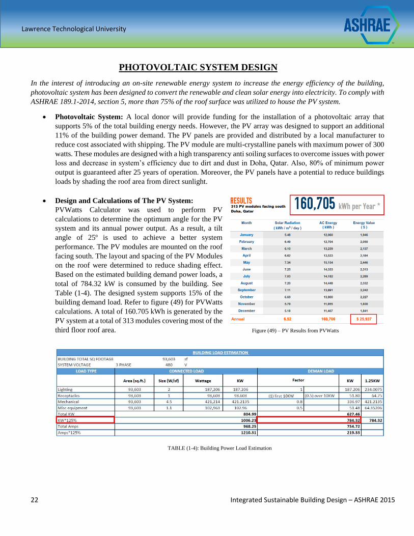
Design and Calculations of The PV System:
PVWatts Calculator was used to perform PV
calculations to determine the optimum angle for the PV
system and its annual power output. As a result, a tilt
angle of 25º is used to achieve a better system
performance. The PV modules are mounted on the roof
facing south. The layout and spacing of the PV Modules
on the roof were determined to reduce shading effect.
Based on the estimated building demand power loads, a
total of 784.32 kW is consumed by the building. See
Table (1-4). The designed system supports 15% of the
building demand load. Refer to figure (49) for PVWatts
calculations. A total of 160.705 kWh is generated by the
PV system at a total of 313 modules covering most of the
third floor roof area. Figure (49) – PV Results from PVWatts
TABLE (1-4): Building Power Load Estimation
Lawrence Technological University
23 Integrated Sustainable Building Design – ASHRAE 2015
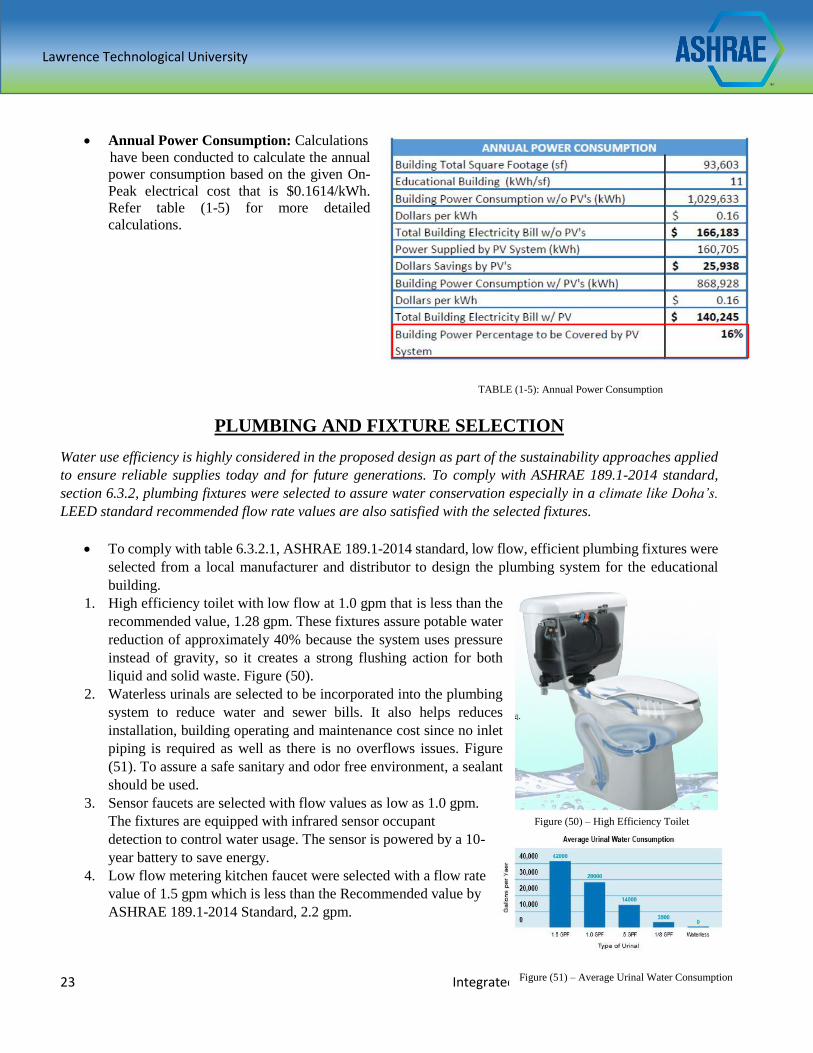
Annual Power Consumption: Calculations
have been conducted to calculate the annual
power consumption based on the given On-
Peak electrical cost that is $0.1614/kWh.
Refer table (1-5) for more detailed
calculations.
TABLE (1-5): Annual Power Consumption
PLUMBING AND FIXTURE SELECTION
Water use efficiency is highly considered in the proposed design as part of the sustainability approaches applied
to ensure reliable supplies today and for future generations. To comply with ASHRAE 189.1-2014 standard,
section 6.3.2, plumbing fixtures were selected to assure water conservation especially in a climate like Doha’s.
LEED standard recommended flow rate values are also satisfied with the selected fixtures.
To comply with table 6.3.2.1, ASHRAE 189.1-2014 standard, low flow, efficient plumbing fixtures were
selected from a local manufacturer and distributor to design the plumbing system for the educational
building.
1. High efficiency toilet with low flow at 1.0 gpm that is less than the
recommended value, 1.28 gpm. These fixtures assure potable water
reduction of approximately 40% because the system uses pressure
instead of gravity, so it creates a strong flushing action for both
liquid and solid waste. Figure (50).
2. Waterless urinals are selected to be incorporated into the plumbing
system to reduce water and sewer bills. It also helps reduces
installation, building operating and maintenance cost since no inlet
piping is required as well as there is no overflows issues. Figure
(51). To assure a safe sanitary and odor free environment, a sealant
should be used.
3. Sensor faucets are selected with flow values as low as 1.0 gpm.
The fixtures are equipped with infrared sensor occupant
detection to control water usage. The sensor is powered by a 10-
year battery to save energy.
4. Low flow metering kitchen faucet were selected with a flow rate
value of 1.5 gpm which is less than the Recommended value by
ASHRAE 189.1-2014 Standard, 2.2 gpm.
Figure (50) – High Efficiency Toilet
Figure (51) – Average Urinal Water Consumption
Lawrence Technological University
24 Integrated Sustainable Building Design – ASHRAE 2015
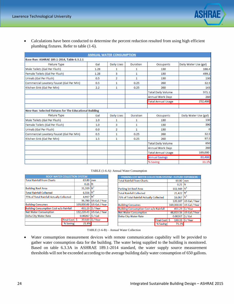
Calculations have been conducted to determine the percent reduction resulted from using high efficient
plumbing fixtures. Refer to table (1-6).
TABLE (1-6-A): Annual Water Consumption
Water consumption measurement devices with remote communication capability will be provided to
gather water consumption data for the building. The water being supplied to the building is monitored.
Based on table 6.3.3A in ASHRAE 189.1-2014 standard, the water supply source measurement
thresholds will not be exceeded according to the average building daily water consumption of 650 gallons.
TABLE (1-6-B) – Annual Water Collection
Lawrence Technological University
25 Integrated Sustainable Building Design – ASHRAE 2015
MECHANICAL SYSTEM DESIGN
When designing the HVAC system, the main objectives were to design a system that meets and exceeds the owner’s
goals of low utility and maintenance costs, easy maintenance, and excellent indoor air quality with a high quality
HVAC system performance. The HVAC system needs to have a very good life cycle cost and provide a high level
of occupant comfort. In addition to this, it must comply with ASHRAE 90.1, ASHRAE 62.1, and ASHRAE 55
standards.
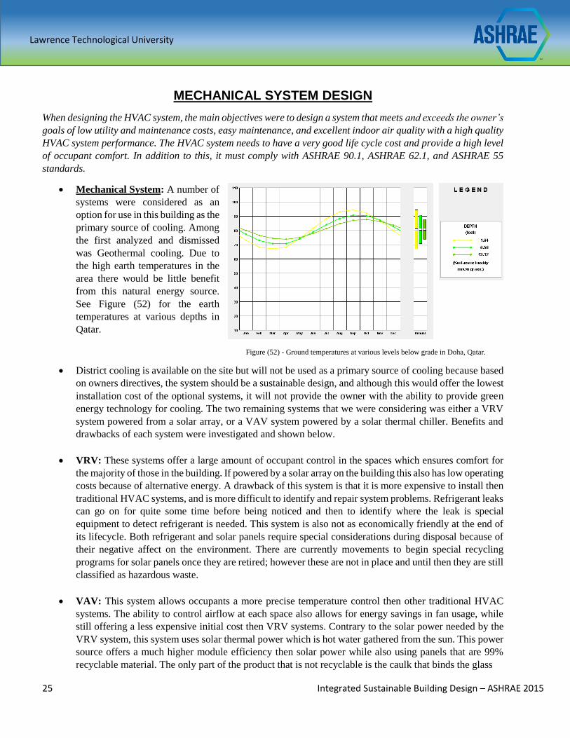
Mechanical System: A number of
systems were considered as an
option for use in this building as the
primary source of cooling. Among
the first analyzed and dismissed
was Geothermal cooling. Due to
the high earth temperatures in the
area there would be little benefit
from this natural energy source.
See Figure (52) for the earth
temperatures at various depths in
Qatar.
District cooling is available on the site but will not be used as a primary source of cooling because based
on owners directives, the system should be a sustainable design, and although this would offer the lowest
installation cost of the optional systems, it will not provide the owner with the ability to provide green
energy technology for cooling. The two remaining systems that we were considering was either a VRV
system powered from a solar array, or a VAV system powered by a solar thermal chiller. Benefits and
drawbacks of each system were investigated and shown below.
VRV: These systems offer a large amount of occupant control in the spaces which ensures comfort for
the majority of those in the building. If powered by a solar array on the building this also has low operating
costs because of alternative energy. A drawback of this system is that it is more expensive to install then
traditional HVAC systems, and is more difficult to identify and repair system problems. Refrigerant leaks
can go on for quite some time before being noticed and then to identify where the leak is special
equipment to detect refrigerant is needed. This system is also not as economically friendly at the end of
its lifecycle. Both refrigerant and solar panels require special considerations during disposal because of
their negative affect on the environment. There are currently movements to begin special recycling
programs for solar panels once they are retired; however these are not in place and until then they are still
classified as hazardous waste.
VAV: This system allows occupants a more precise temperature control then other traditional HVAC
systems. The ability to control airflow at each space also allows for energy savings in fan usage, while
still offering a less expensive initial cost then VRV systems. Contrary to the solar power needed by the
VRV system, this system uses solar thermal power which is hot water gathered from the sun. This power
source offers a much higher module efficiency then solar power while also using panels that are 99%
recyclable material. The only part of the product that is not recyclable is the caulk that binds the glass
Figure (52) - Ground temperatures at various levels below grade in Doha, Qatar.
Lawrence Technological University
26 Integrated Sustainable Building Design – ASHRAE 2015
tube element in the collector to the metal frame. This system was chosen for use in our project because
of the practicality, energy efficiency, and economical benefits that showed in our initial analysis.
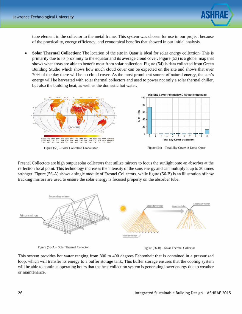
Solar Thermal Collection: The location of the site in Qatar is ideal for solar energy collection. This is
primarily due to its proximity to the equator and its average cloud cover. Figure (53) is a global map that
shows what areas are able to benefit most from solar collection. Figure (54) is data collected from Green
Building Studio which shows how much cloud cover can be expected on the site and shows that over
70% of the day there will be no cloud cover. As the most prominent source of natural energy, the sun’s
energy will be harvested with solar thermal collectors and used to power not only a solar thermal chiller,
but also the building heat, as well as the domestic hot water.
Fresnel Collectors are high output solar collectors that utilize mirrors to focus the sunlight onto an absorber at the
reflection focal point. This technology increases the intensity of the suns energy and can multiply it up to 30 times
stronger. Figure (56-A) shows a single module of Fresnel Collectors, while figure (56-B) is an illustration of how
tracking mirrors are used to ensure the solar energy is focused properly on the absorber tube.
This system provides hot water ranging from 300 to 400 degrees Fahrenheit that is contained in a pressurized
loop, which will transfer its energy to a buffer storage tank. This buffer storage ensures that the cooling system
will be able to continue operating hours that the heat collection system is generating lower energy due to weather
or maintenance.
Figure (53) – Solar Collection Global Map Figure (54) – Total Sky Cover in Doha, Qatar
Figure (56-B) – Solar Thermal Collector Figure (56-A)– Solar Thermal Collector
Lawrence Technological University
27 Integrated Sustainable Building Design – ASHRAE 2015
Solar Hot Water Uses: There are a number of uses in a building for hot water, and if sized properly, the
solar hot water collectors can provide the hot water for all of these uses. The solar hot water system in
this building is used to provide hot water to the following systems: domestic hot water, HVAC heating
hot water, and absorption chiller thermal power.
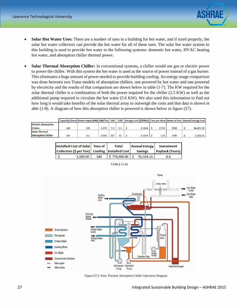
Solar Thermal Absorption Chiller: In conventional systems, a chiller would use gas or electric power
to power the chiller. With this system the hot water is used as the source of power instead of a gas burner.
This eliminates a huge amount of power needed to provide building cooling. An energy usage comparison
was done between two Trane models of absorption chillers, one powered by hot water and one powered
by electricity and the results of that comparison are shown below in table (1-7). The KW required for the
solar thermal chiller is a combination of both the power required for the chiller (2.5 KW) as well as the
additional pump required to circulate the hot water (5.6 KW). We also used this information to find out
how long it would take benefits of the solar thermal array to outweigh the costs and that data is shown in
able (1-8). A diagram of how this absorption chiller is powered is shown below in figure (57).
TABLE (1-7): Electric and Solar Thermal Absorption Chiller comparison
TABLE (1-8)
Figure (57): Solar Thermal Absorption Chiller Operation Diagram
Lawrence Technological University
28 Integrated Sustainable Building Design – ASHRAE 2015
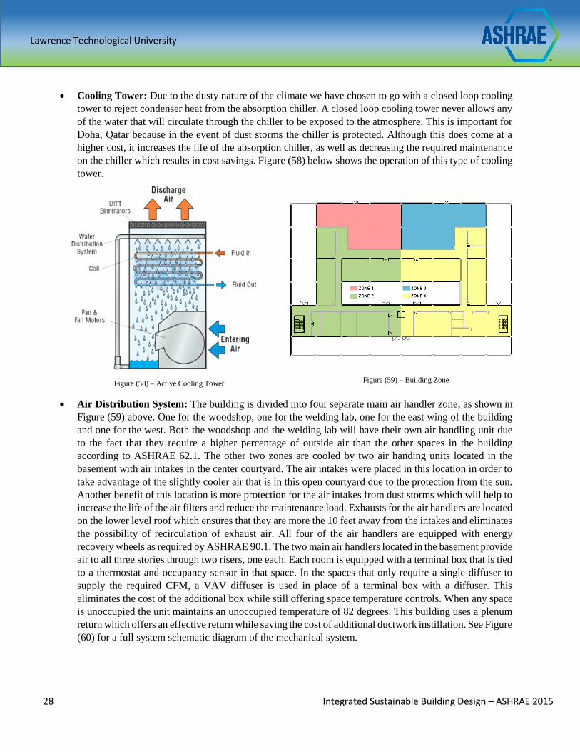
Cooling Tower: Due to the dusty nature of the climate we have chosen to go with a closed loop cooling
tower to reject condenser heat from the absorption chiller. A closed loop cooling tower never allows any
of the water that will circulate through the chiller to be exposed to the atmosphere. This is important for
Doha, Qatar because in the event of dust storms the chiller is protected. Although this does come at a
higher cost, it increases the life of the absorption chiller, as well as decreasing the required maintenance
on the chiller which results in cost savings. Figure (58) below shows the operation of this type of cooling
tower.
Air Distribution System: The building is divided into four separate main air handler zone, as shown in
Figure (59) above. One for the woodshop, one for the welding lab, one for the east wing of the building
and one for the west. Both the woodshop and the welding lab will have their own air handling unit due
to the fact that they require a higher percentage of outside air than the other spaces in the building
according to ASHRAE 62.1. The other two zones are cooled by two air handing units located in the
basement with air intakes in the center courtyard. The air intakes were placed in this location in order to
take advantage of the slightly cooler air that is in this open courtyard due to the protection from the sun.
Another benefit of this location is more protection for the air intakes from dust storms which will help to
increase the life of the air filters and reduce the maintenance load. Exhausts for the air handlers are located
on the lower level roof which ensures that they are more the 10 feet away from the intakes and eliminates
the possibility of recirculation of exhaust air. All four of the air handlers are equipped with energy
recovery wheels as required by ASHRAE 90.1. The two main air handlers located in the basement provide
air to all three stories through two risers, one each. Each room is equipped with a terminal box that is tied
to a thermostat and occupancy sensor in that space. In the spaces that only require a single diffuser to
supply the required CFM, a VAV diffuser is used in place of a terminal box with a diffuser. This
eliminates the cost of the additional box while still offering space temperature controls. When any space
is unoccupied the unit maintains an unoccupied temperature of 82 degrees. This building uses a plenum
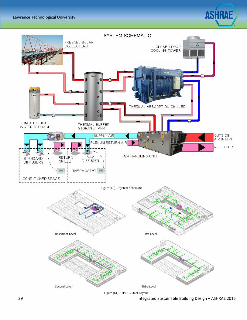
return which offers an effective return while saving the cost of additional ductwork instillation. See Figure
(60) for a full system schematic diagram of the mechanical system.
Figure (58) – Active Cooling Tower Figure (59) – Building Zone
Lawrence Technological University
29 Integrated Sustainable Building Design – ASHRAE 2015
Figure (60) – System Schematic
Figure (61) – HVAC Duct Layout
Basement Level First Level
Second Level Third Level
Lawrence Technological University
30 Integrated Sustainable Building Design – ASHRAE 2015
Indoor Environmental Quality
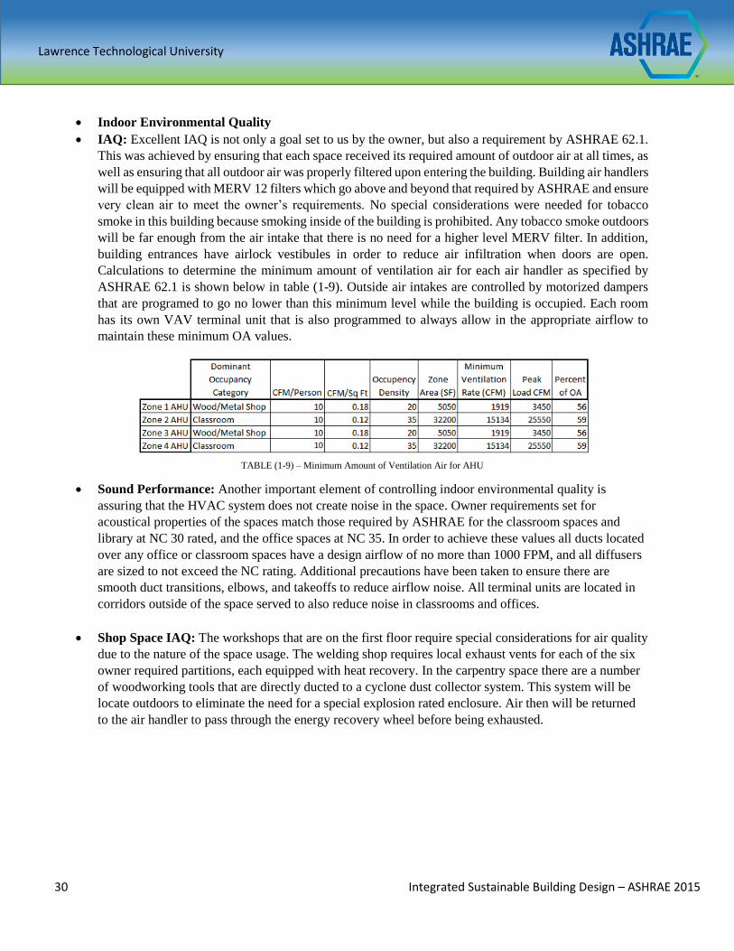
IAQ: Excellent IAQ is not only a goal set to us by the owner, but also a requirement by ASHRAE 62.1.
This was achieved by ensuring that each space received its required amount of outdoor air at all times, as
well as ensuring that all outdoor air was properly filtered upon entering the building. Building air handlers
will be equipped with MERV 12 filters which go above and beyond that required by ASHRAE and ensure
very clean air to meet the owner’s requirements. No special considerations were needed for tobacco
smoke in this building because smoking inside of the building is prohibited. Any tobacco smoke outdoors
will be far enough from the air intake that there is no need for a higher level MERV filter. In addition,
building entrances have airlock vestibules in order to reduce air infiltration when doors are open.
Calculations to determine the minimum amount of ventilation air for each air handler as specified by
ASHRAE 62.1 is shown below in table (1-9). Outside air intakes are controlled by motorized dampers
that are programed to go no lower than this minimum level while the building is occupied. Each room
has its own VAV terminal unit that is also programmed to always allow in the appropriate airflow to
maintain these minimum OA values.
Sound Performance: Another important element of controlling indoor environmental quality is
assuring that the HVAC system does not create noise in the space. Owner requirements set for
acoustical properties of the spaces match those required by ASHRAE for the classroom spaces and
library at NC 30 rated, and the office spaces at NC 35. In order to achieve these values all ducts located
over any office or classroom spaces have a design airflow of no more than 1000 FPM, and all diffusers
are sized to not exceed the NC rating. Additional precautions have been taken to ensure there are
smooth duct transitions, elbows, and takeoffs to reduce airflow noise. All terminal units are located in
corridors outside of the space served to also reduce noise in classrooms and offices.
Shop Space IAQ: The workshops that are on the first floor require special considerations for air quality
due to the nature of the space usage. The welding shop requires local exhaust vents for each of the six
owner required partitions, each equipped with heat recovery. In the carpentry space there are a number
of woodworking tools that are directly ducted to a cyclone dust collector system. This system will be
locate outdoors to eliminate the need for a special explosion rated enclosure. Air then will be returned
to the air handler to pass through the energy recovery wheel before being exhausted.
TABLE (1-9) – Minimum Amount of Ventilation Air for AHU
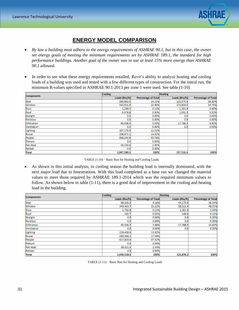
Lawrence Technological University
31 Integrated Sustainable Building Design – ASHRAE 2015
ENERGY MODEL COMPARISON
By law a building must adhere to the energy requirements of ASHRAE 90.1, but in this case, the owner
set energy goals of meeting the minimum requirements set by ASHRAE 189.1, the standard for high
performance buildings. Another goal of the owner was to use at least 15% more energy than ASHRAE
90.1 allowed.
In order to see what these energy requirements entailed, Revit’s ability to analyze heating and cooling
loads of a building was used and tested with a few different types of construction. For the initial run, the
minimum R-values specified in ASHRAE 90.1-2013 per zone 1 were used. See table (1-10)
As shown in this initial analysis, in cooling season the building load is internally dominated, with the
next major load due to fenestrations. With this load completed as a base run we changed the material
values to meet those required by ASHRAE 189.1-2014 which was the required minimum values to
follow. As shown below in table (1-11), there is a good deal of improvement in the cooling and heating
load in the building.
TABLE (1-10) – Basic Run for Heating and Cooling Loads
TABLE (1-11) – Basic Run for Heating and Cooling Loads
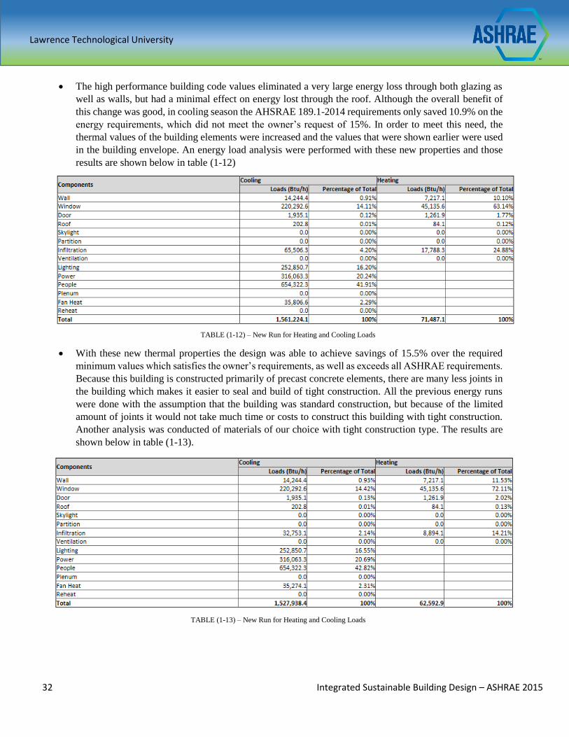
Lawrence Technological University
32 Integrated Sustainable Building Design – ASHRAE 2015
The high performance building code values eliminated a very large energy loss through both glazing as
well as walls, but had a minimal effect on energy lost through the roof. Although the overall benefit of
this change was good, in cooling season the AHSRAE 189.1-2014 requirements only saved 10.9% on the
energy requirements, which did not meet the owner’s request of 15%. In order to meet this need, the
thermal values of the building elements were increased and the values that were shown earlier were used
in the building envelope. An energy load analysis were performed with these new properties and those
results are shown below in table (1-12)
With these new thermal properties the design was able to achieve savings of 15.5% over the required
minimum values which satisfies the owner’s requirements, as well as exceeds all ASHRAE requirements.
Because this building is constructed primarily of precast concrete elements, there are many less joints in
the building which makes it easier to seal and build of tight construction. All the previous energy runs
were done with the assumption that the building was standard construction, but because of the limited
amount of joints it would not take much time or costs to construct this building with tight construction.
Another analysis was conducted of materials of our choice with tight construction type. The results are
shown below in table (1-13).
TABLE (1-12) – New Run for Heating and Cooling Loads
TABLE (1-13) – New Run for Heating and Cooling Loads
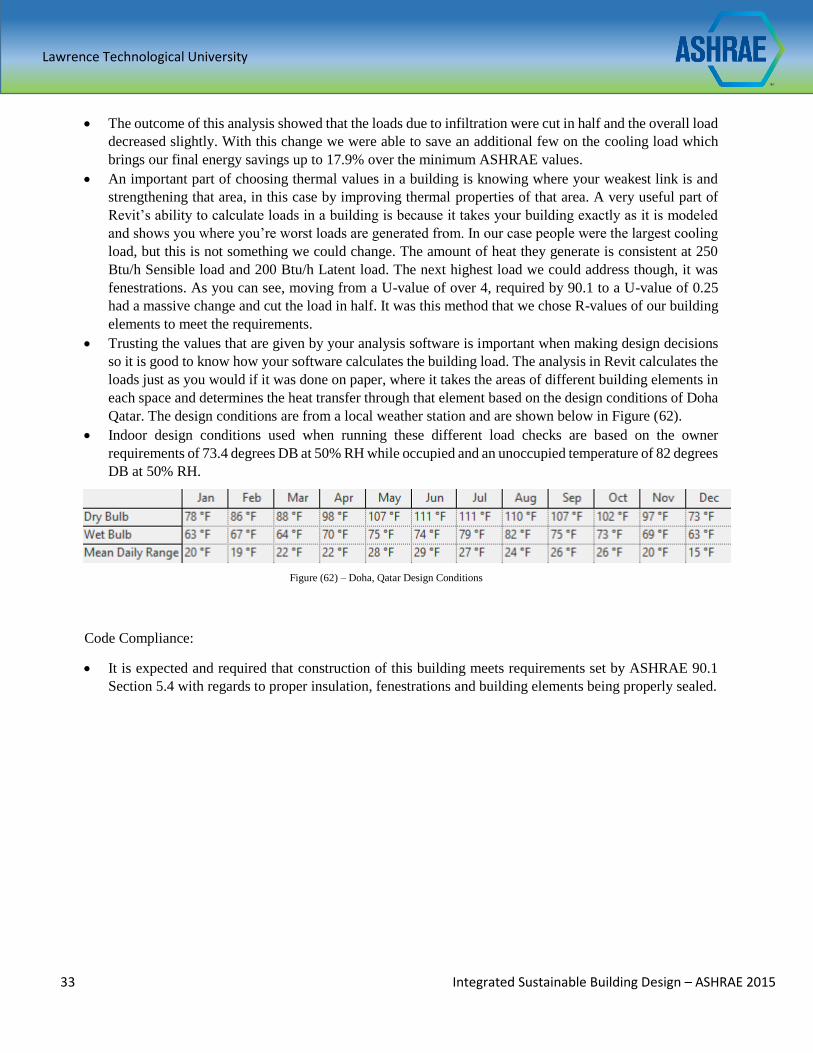
Lawrence Technological University
33 Integrated Sustainable Building Design – ASHRAE 2015
The outcome of this analysis showed that the loads due to infiltration were cut in half and the overall load
decreased slightly. With this change we were able to save an additional few on the cooling load which
brings our final energy savings up to 17.9% over the minimum ASHRAE values.
An important part of choosing thermal values in a building is knowing where your weakest link is and
strengthening that area, in this case by improving thermal properties of that area. A very useful part of
Revit’s ability to calculate loads in a building is because it takes your building exactly as it is modeled
and shows you where you’re worst loads are generated from. In our case people were the largest cooling
load, but this is not something we could change. The amount of heat they generate is consistent at 250
Btu/h Sensible load and 200 Btu/h Latent load. The next highest load we could address though, it was
fenestrations. As you can see, moving from a U-value of over 4, required by 90.1 to a U-value of 0.25
had a massive change and cut the load in half. It was this method that we chose R-values of our building
elements to meet the requirements.
Trusting the values that are given by your analysis software is important when making design decisions
so it is good to know how your software calculates the building load. The analysis in Revit calculates the
loads just as you would if it was done on paper, where it takes the areas of different building elements in
each space and determines the heat transfer through that element based on the design conditions of Doha
Qatar. The design conditions are from a local weather station and are shown below in Figure (62).
Indoor design conditions used when running these different load checks are based on the owner
requirements of 73.4 degrees DB at 50% RH while occupied and an unoccupied temperature of 82 degrees
DB at 50% RH.
Code Compliance:
It is expected and required that construction of this building meets requirements set by ASHRAE 90.1
Section 5.4 with regards to proper insulation, fenestrations and building elements being properly sealed.
Figure (62) – Doha, Qatar Design Conditions
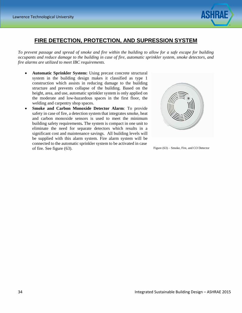
Lawrence Technological University
34 Integrated Sustainable Building Design – ASHRAE 2015
FIRE DETECTION, PROTECTION, AND SUPRESSION SYSTEM
To prevent passage and spread of smoke and fire within the building to allow for a safe escape for building
occupants and reduce damage to the building in case of fire, automatic sprinkler system, smoke detectors, and
fire alarms are utilized to meet IBC requirements.
Automatic Sprinkler System: Using precast concrete structural
system in the building design makes it classified as type 1
construction which assists in reducing damage to the building
structure and prevents collapse of the building. Based on the
height, area, and use, automatic sprinkler system is only applied on
the moderate and low-hazardous spaces in the first floor, the
welding and carpentry shop spaces.
Smoke and Carbon Monoxide Detector Alarm: To provide
safety in case of fire, a detection system that integrates smoke, heat
and carbon monoxide sensors is used to meet the minimum
building safety requirements. The system is compact in one unit to
eliminate the need for separate detectors which results in a
significant cost and maintenance savings. All building levels will
be supplied with this alarm system. Fire alarm system will be
connected to the automatic sprinkler system to be activated in case
of fire. See figure (63).
Figure (63) – Smoke, Fire, and CO Detector
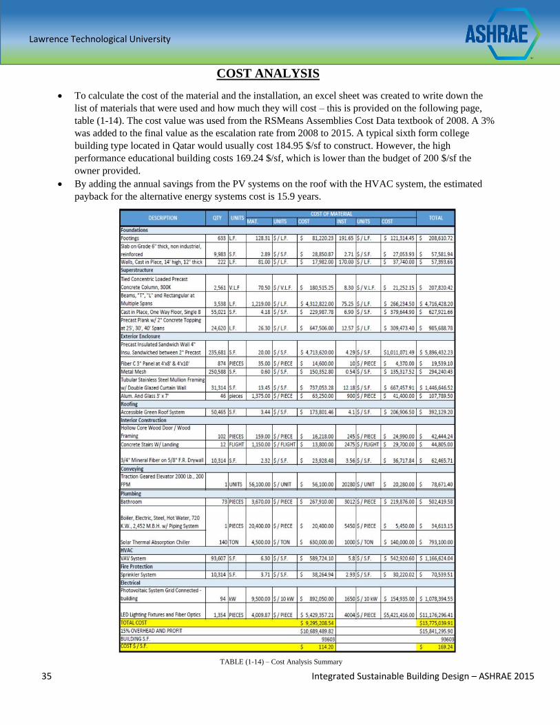
Lawrence Technological University
35 Integrated Sustainable Building Design – ASHRAE 2015
TABLE (1-14) – Cost Analysis Summary
COST ANALYSIS
To calculate the cost of the material and the installation, an excel sheet was created to write down the
list of materials that were used and how much they will cost – this is provided on the following page,
table (1-14). The cost value was used from the RSMeans Assemblies Cost Data textbook of 2008. A 3%
was added to the final value as the escalation rate from 2008 to 2015. A typical sixth form college
building type located in Qatar would usually cost 184.95 $/sf to construct. However, the high
performance educational building costs 169.24 $/sf, which is lower than the budget of 200 $/sf the
owner provided.
By adding the annual savings from the PV systems on the roof with the HVAC system, the estimated
payback for the alternative energy systems cost is 15.9 years.
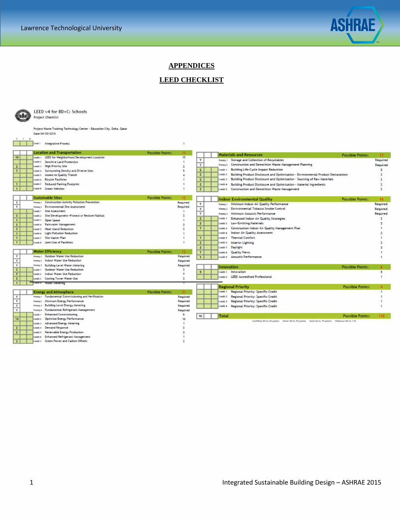
Lawrence Technological University
1 Integrated Sustainable Building Design – ASHRAE 2015
APPENDICES
LEED CHECKLIST
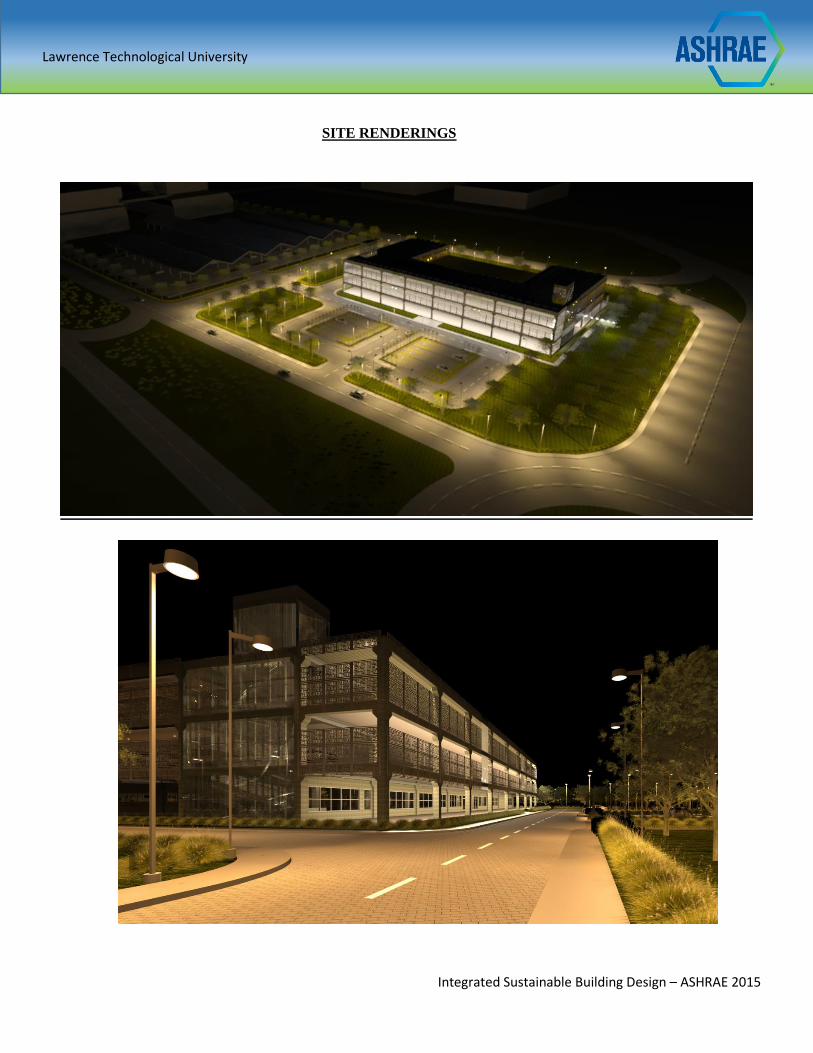
Lawrence Technological University
Integrated Sustainable Building Design – ASHRAE 2015
SITE RENDERINGS
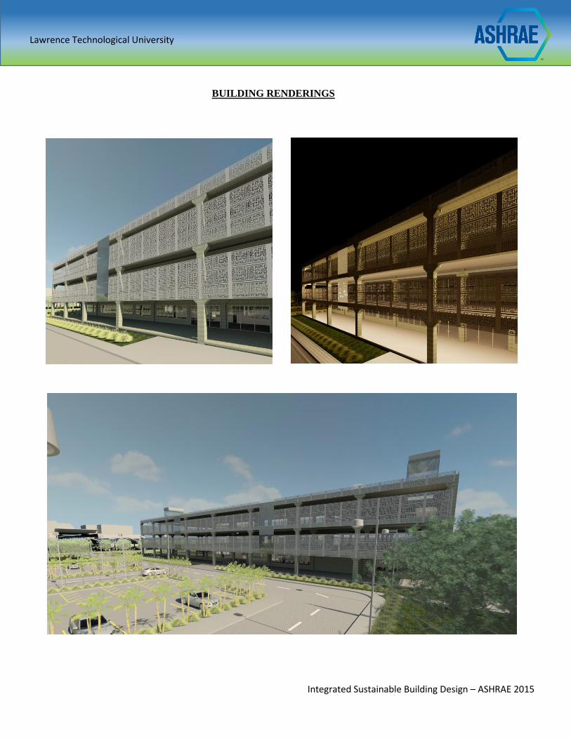
Lawrence Technological University
Integrated Sustainable Building Design – ASHRAE 2015
BUILDING RENDERINGS
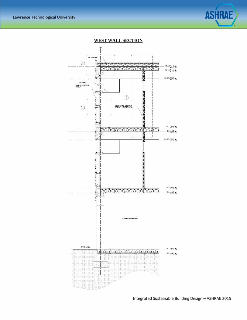
Lawrence Technological University
Integrated Sustainable Building Design – ASHRAE 2015
WEST WALL SECTION
Lawrence Technological University
Integrated Sustainable Building Design – ASHRAE 2015
REFRENCES
"AltusGroup." AltusGroup. N.p., 6 Jan. 2015. Web. 03 May 2015.
ASHRAE Standard: Thermal Environmental Conditions for Human Occupancy. Atlanta, GA: ASHRAE, 2010.
Print.
Bialous, S. Aguinaga. "ASHRAE Standard 62: Tobacco Industry's Influence over National Ventilation
Standards." Tobacco Control 11.4 (2002): 315-28. Web. 3 May 2015.
"Bring the Sun Inside." Parans. N.p., n.d. Web. 20 Apr. 2015.
"Doha Monthly Climate Average, Qatar." Doha, Qatar Weather Averages. N.p., n.d. Web. 22 Apr. 2015.
"Education City Pioneers Electric-bike Sharing System." Gulf-Times. N.p., n.d. Web. 03 Feb. 2015.
"Emirates Glass." Emirates Glass. N.p., n.d. Web. 30 Jan. 2015.
Energy Standard for Buildings except Low-rise Residential Buildings. Atlanta, GA: American Society of
Heating, Refrigerating and Air-Conditioning Engineers, 2010. Print.
"FibreC by Rieder - United States - Glassfibre Reinforced Concrete Panels for Exterior | Interior | Special."
FibreC by Rieder - United States - Glassfibre Reinforced Concrete Panels for Exterior | Interior | Special. N.p.,
3 Jan. 2015. Web. 03 May 2015.
"Institute of Public Administration by Louis I. Kahn at GreatBuildings." GreatBuildings. N.p., n.d. Web. 22
Mar. 2015.
Kaufman, John E. IES Lighting Handbook. New York, NY: Illuminating Engineering Society of North
America, 1981. Print.
"LED Lighting | Commercial Lighting." GE Lighting North America. N.p., n.d. Web. 2 Mar. 2015.
"M60-250Wp, The No.1 Performing Solar PV Panel in the World." Philadelphia Solar Photovoltaic. N.p., n.d.
Web. 1 Apr. 2015.
N.p., 7 Jan. 2015. Web. 3 May 2015.
"Qatar Education City - Education Zones - TEN Education." Qatar Education City - Education Zones - TEN
Education. N.p., n.d. Web. 22 Feb. 2015.
"Qatar Foundation Advances on Plans to Establish Car-free Campus - Doha News." Doha News. N.p., 20 July
2014. Web. 22 Mar. 2015.
"Qatar Foundation to Get Turnkey Tram System from Siemens." - Siemens Global Website. N.p., n.d. Web. 12
Apr. 2015.
"QATAR TRIBUNE." N.p., n.d. Web. 28 Apr. 2015.
"Qatar's First Education City Tram Rolls out." Rwg. N.p., n.d. Web. 10 Mar. 2015.
Standard for the Design of High-performance Green Buildings: Except Low-rise Residential Buildings. Atlanta,
GA: American Society of Heating, Refrigerating, and Air-Conditioning Engineers, 2009. Print.
"SteelBuilt Curtainwall Systems | Structural Glazing Systems." SteelBuilt Curtainwall Systems | Structural
Glazing Systems. N.p., n.d. Web. 03 Mar. 2015.
"Thermal Insulation Systems for the Building Envelope." Applications. N.p., n.d. Web. 03 Feb. 2015.
"Trees and Vegetation | Heat Island Effect | US EPA." EPA. Environmental Protection Agency, n.d. Web. 22
Apr. 2015.
2012 International Building Code. Country Club Hills, IL: ICC, 2011. Print.
"WeatherSpark Beta." Average Weather For Doha, Qatar. N.p., n.d. Web. 21 Feb. 2015.
" Welcome to Oldcastle Precast Reliability Is the Cornerstone of Everything We Do. It's What Makes Us the
Leading Manufacturer of Precast Concrete in the U.S. and What Thousands of Satisfied Customers Have Come
to Expect." Oldcastle Precast, Leading U.S. Manufacturer of Precast Concrete. N.p., n.d. Web. 03 Mar. 2015.
"WHAT'S NEW ." Zurn Engineered Water Solutions. N.p., n.d. Web. 1 May 2015.
"Fresnel Collector." Industrial Solar:. N.p., n.d. Web. 15 Apr. 2015.
"Chiller | Trane Commercial." Trane-Commercial. N.p., n.d. Web. 04 May 2015.