Embed Size (px)
Citation preview

5/13/2018 ASIC Protocol (Eng) - slidepdf.com
http://slidepdf.com/reader/full/asic-protocol-eng 1/7
ASIC Protocol - 1
ASIC Protocol
1. OverviewThis driver supports the ASI communication protocol of ASI Controls. This protocol provides
communication access to a network of ASI controllers from XPanel.
2. Communication Setup : XPanel
(1) Create a new device.
For creating a new device activate the menu ‘Tools’->’I/O Devices’ or icon in tool-
bar. Following picture shows the first step of creating a new device.
I/O Device Name
Give a device name. This name will be used in the TAG configuration window of
database accompanied by the ‘Station Name’.
(2) Select a device type : ‘ASI Communication Protocol’
After selecting the ‘OK’ button of previous step, ‘Serial Communication Configuration’
dialog box will be popped up as shown in following picture.

5/13/2018 ASIC Protocol (Eng) - slidepdf.com
http://slidepdf.com/reader/full/asic-protocol-eng 2/7
ASIC Protocol - 2
In this window, select the ‘Device Type’ as ‘ASI Communication Protocol’ and configure
the proper serial communication parameters. Ensure that those parameters are matched
with PLC configuration.
Local ID
The host address of XPanel has to be designated in this window. It is 16 bits value
between 1 and 65535. There are reserved address ranges which cannot be used
by XPanel or DDC. Please refer to the DDC manual from ASI Controls for more
information about the address.
(3) Create a station
Move to the ‘Station’ tab of ‘Serial Communication Configuration’ dialog box.
In this dialog box, all the connected PLC stations can be configured and registered to the
XPanel. Each field can be configured with following rules.
Station Name
Give a name to the PLC. This name will be used in the database window
accompanied with the ‘Device Name’.
Station Type
Choose the type of connected PLC among the “ASIC”.
Network ID
This field has no effect.

5/13/2018 ASIC Protocol (Eng) - slidepdf.com
http://slidepdf.com/reader/full/asic-protocol-eng 3/7
ASIC Protocol - 3
Station No.
Specify a decimal number between 1 and 65535. This number must be matched
with the node address of the DDC.
16Bit Data Swap
This option swaps bytes of all word or double word sized data. Following diagram
shows an example of byte swapping.
Almost all of the data type will be influenced by this option except INT8 / UINT8 /
BCD8 / UBCD8.
32Bit Data Swap
This option swaps words of all double word sized data. Following diagram shows
an example of word swapping.
1234ABCDh ABCD1234hDouble Word Data
INT32 / UINT32 / BCD32 / UBCD32 / FLOAT type of TAG values will be influenced
by this option.
Using Checksum
This field has no effect. This communication driver always checks the check-sum.

5/13/2018 ASIC Protocol (Eng) - slidepdf.com
http://slidepdf.com/reader/full/asic-protocol-eng 4/7
ASIC Protocol - 4
Comm. Error Message Pop Up
If this item is checked, XPanel displays a communication error notification
message at every Rx and Tx error.
Otherwise(unchecked), XPanel does not display the message at data receive error.Only when there is data transmit (writing a TAG value to the station) error, the
notification message is popped up. This message box will be closed automatically
about 5 seconds after.

5/13/2018 ASIC Protocol (Eng) - slidepdf.com
http://slidepdf.com/reader/full/asic-protocol-eng 5/7
ASIC Protocol - 5
3. Data Address
XPanel supports reading object and table data from DDC. These two data can be referencedby following TAG address format.
Obj No / Table No
Designate the object (table) number of data location. Please refer to the object definition
of connected DDC, for more information about object.
Size
Designate the data type. It can be 1 (BYTE) or 2 (WORD).
Offset
Designate the byte offset within the table.
Index
Designate the assigned index number within the given object.
Attribute
Designate the attribute number of data.
:Bit No
Designate the bit number. This bit address notation is used in digital TAG. Notice that
the TAG with this bit number only can be read. That is, the digital TAG writing is not
supported with ASIC protocol driver.
Bit number has to be within the range of data size. In case of a table (T) or object (O)
with size 1 (BYTE), bit number can be between 0 and 7. Elsewhere, object with size 2
(WORD), bit number can be between 0 and 15.
[Address Examples]
O33.2.0.0 : Object 33, WORD, Index 0, Attribute 0
T10.0 : Table 10, Byte offset 0
O32.1.0.8 : Object 32, BYTE, Index 0, Attribute 8
O3.2.11.0:0 : Object 3, WORD, Index 11, Attribute 0, Bit 0
[Object]
O[Obj No].[Size].[Index].[Attribute](:Bit No)
[Table]
T[Table No].[Offset](:Bit No)
5/13/2018 ASIC Protocol (Eng) - slidepdf.com
http://slidepdf.com/reader/full/asic-protocol-eng 6/7
ASIC Protocol - 6
[TAG Data Type]
ASIC DDC supports two types of data, BYTE and WORD. If the data type of TAG was
larger than that, XPanel will read next continuously positioned data for making designated
data. For example, if UINT32 type of TAG referred to the address of T1.2, XPanel will readT1.2, T1.3, T1.4 and T1.5 for assembling the UINT32 data.
5/13/2018 ASIC Protocol (Eng) - slidepdf.com
http://slidepdf.com/reader/full/asic-protocol-eng 7/7
ASIC Protocol - 7
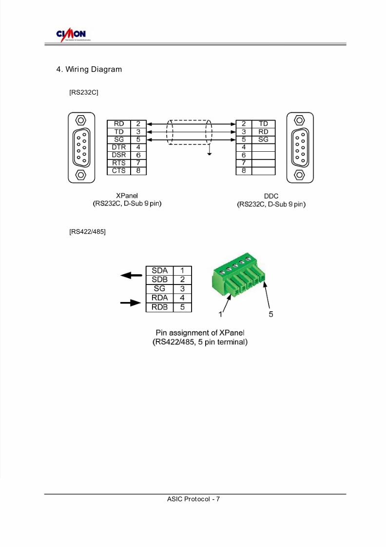
4. Wiring Diagram
[RS232C]
[RS422/485]