Embed Size (px)
Citation preview
ASL: Auburn Simulation Languageand
AUSIM: Auburn University SIMulator
Chuck StroudProfessor
Electrical & Computer EngineeringAuburn University
C. E. Stroud (1/05) ASL Auburn Simulation Language 2
Overview of ASL
ASL: Auburn Simulation LanguageA positional notation hardware description language for digital logicUsed with AUSIM (Auburn University SIMulator) for
Logic simulationDesign verification
Fault simulationGate-level stuck-at faultsBridging faults (shorts between signals)
C. E. Stroud (1/05) ASL Auburn Simulation Language 3
DelimitersUsed to separate all:
KeywordsSome reserved characters
Specifically ‘#’ and ‘;’
NamesGate namesSignal (net) names
Includes:Space, tab, and new line
Can be used freelyMissing delimiter is a frequent source of syntax errors
C. E. Stroud (1/05) ASL Auburn Simulation Language 4
Reserved CharactersCan not (or should not) be used in names:
‘_’ (underscore)Used to construct names when flattening hierarchy
‘#’ (pound sign)Denotes beginning of comment statement
‘;’ (semicolon)Denotes end of statement
‘:’ (colon)Denotes keyword
‘[’ and ‘]’Used for bus notation
Supported only in advanced versions of AUSIM
C. E. Stroud (1/05) ASL Auburn Simulation Language 5
KeywordsCan be all capital or all small letters
Always end with colon ‘:’Include:
CKT: (ckt:) and SUBCKT: (subckt:)Denotes circuit and subcircuit statements
IN: (in:) and OUT: (out:)Denotes inputs and outputs of circuit, subcircuit, or gate
CON: (con:)Denotes configuration bits for FPGAs/CPLDs
Supported only in advanced versions of AUSIMAND: (and:), OR: (or:), NAND: (nand:), NOR: (nor:), & NOT: (not:)
Denotes elementary logic gate component statementsUser defined subcircuit names
C. E. Stroud (1/05) ASL Auburn Simulation Language 6
More KeywordsFunctional models
Supported only in advanced versions of AUSIMInclude:
XOR: (xor:) and NXOR: (nxor:)Denotes exclusive-OR and exclusive-NOR gates
MUX2: (mux2:)Denotes 2-to-1 multiplexer
DFF: (dff:) and NDFF: (ndff:)Denotes rising and falling edge-triggered D flip-flops
LAT: (lat:) and NLAT: (nlat:)Denotes active high and active low level-sensitive D latches
C. E. Stroud (1/05) ASL Auburn Simulation Language 7
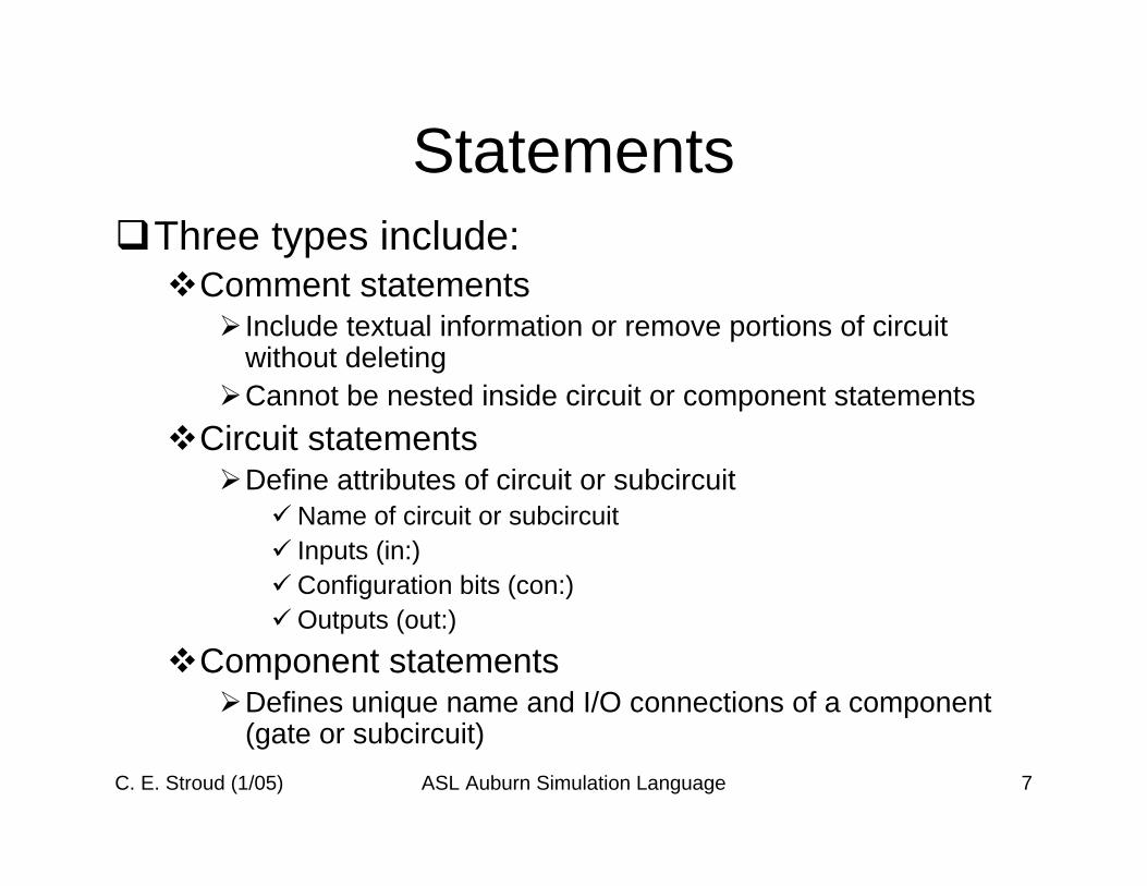
StatementsThree types include:
Comment statementsInclude textual information or remove portions of circuit without deletingCannot be nested inside circuit or component statements
Circuit statementsDefine attributes of circuit or subcircuit
Name of circuit or subcircuitInputs (in:)Configuration bits (con:)Outputs (out:)
Component statementsDefines unique name and I/O connections of a component (gate or subcircuit)
C. E. Stroud (1/05) ASL Auburn Simulation Language 8
Comment Statements
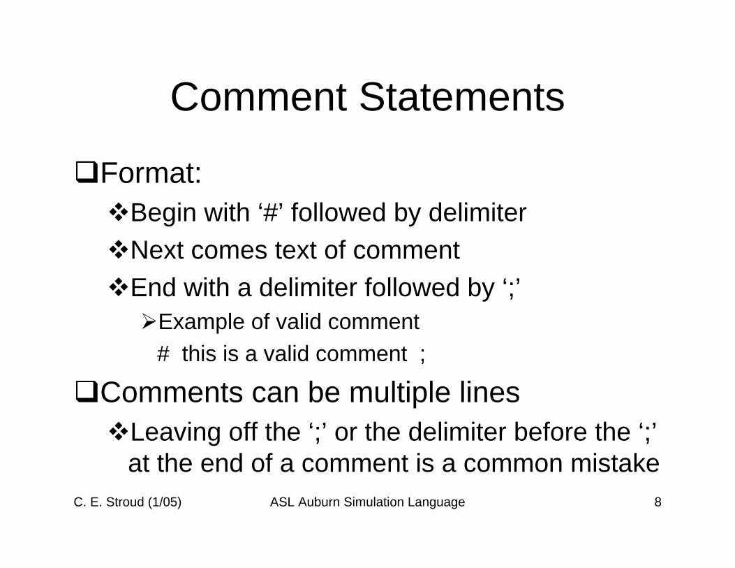
Format:Begin with ‘#’ followed by delimiterNext comes text of commentEnd with a delimiter followed by ‘;’
Example of valid comment# this is a valid comment ;
Comments can be multiple linesLeaving off the ‘;’ or the delimiter before the ‘;’ at the end of a comment is a common mistake
C. E. Stroud (1/05) ASL Auburn Simulation Language 9
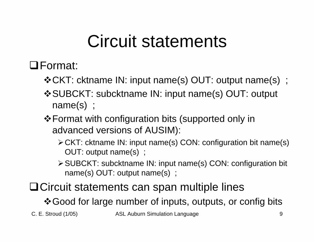
Circuit statementsFormat:
CKT: cktname IN: input name(s) OUT: output name(s) ;SUBCKT: subcktname IN: input name(s) OUT: output name(s) ;Format with configuration bits (supported only in advanced versions of AUSIM):
CKT: cktname IN: input name(s) CON: configuration bit name(s) OUT: output name(s) ;SUBCKT: subcktname IN: input name(s) CON: configuration bit name(s) OUT: output name(s) ;
Circuit statements can span multiple linesGood for large number of inputs, outputs, or config bits
C. E. Stroud (1/05) ASL Auburn Simulation Language 10
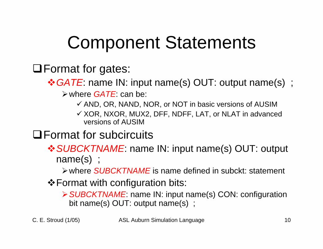
Component StatementsFormat for gates:
GATE: name IN: input name(s) OUT: output name(s) ;where GATE: can be:
AND, OR, NAND, NOR, or NOT in basic versions of AUSIMXOR, NXOR, MUX2, DFF, NDFF, LAT, or NLAT in advanced versions of AUSIM
Format for subcircuitsSUBCKTNAME: name IN: input name(s) OUT: output name(s) ;
where SUBCKTNAME is name defined in subckt: statementFormat with configuration bits:
SUBCKTNAME: name IN: input name(s) CON: configuration bit name(s) OUT: output name(s) ;
C. E. Stroud (1/05) ASL Auburn Simulation Language 11
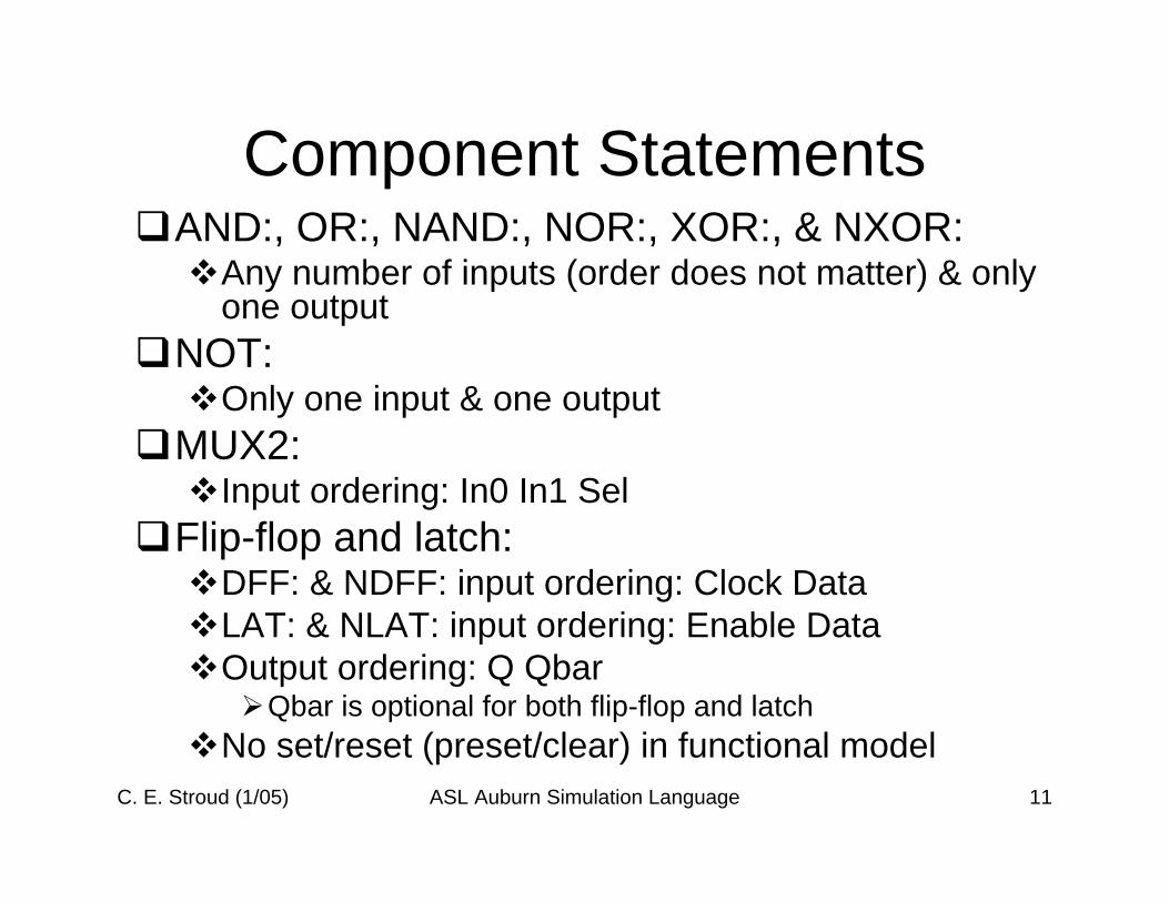
Component StatementsAND:, OR:, NAND:, NOR:, XOR:, & NXOR:
Any number of inputs (order does not matter) & only one output
NOT: Only one input & one output
MUX2:Input ordering: In0 In1 Sel
Flip-flop and latch:DFF: & NDFF: input ordering: Clock DataLAT: & NLAT: input ordering: Enable DataOutput ordering: Q Qbar
Qbar is optional for both flip-flop and latchNo set/reset (preset/clear) in functional model
C. E. Stroud (1/05) ASL Auburn Simulation Language 12
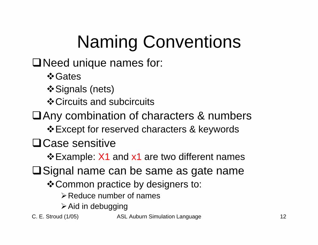
Naming ConventionsNeed unique names for:
GatesSignals (nets)Circuits and subcircuits
Any combination of characters & numbersExcept for reserved characters & keywords
Case sensitiveExample: X1 and x1 are two different names
Signal name can be same as gate nameCommon practice by designers to:
Reduce number of namesAid in debugging
C. E. Stroud (1/05) ASL Auburn Simulation Language 13
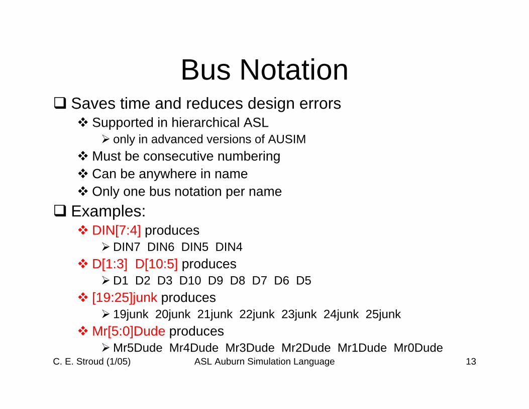
Bus NotationSaves time and reduces design errors
Supported in hierarchical ASLonly in advanced versions of AUSIM
Must be consecutive numberingCan be anywhere in nameOnly one bus notation per name
Examples:DIN[7:4] produces
DIN7 DIN6 DIN5 DIN4D[1:3] D[10:5] produces
D1 D2 D3 D10 D9 D8 D7 D6 D5[19:25]junk produces
19junk 20junk 21junk 22junk 23junk 24junk 25junkMr[5:0]Dude produces
Mr5Dude Mr4Dude Mr3Dude Mr2Dude Mr1Dude Mr0Dude
C. E. Stroud (1/05) ASL Auburn Simulation Language 14
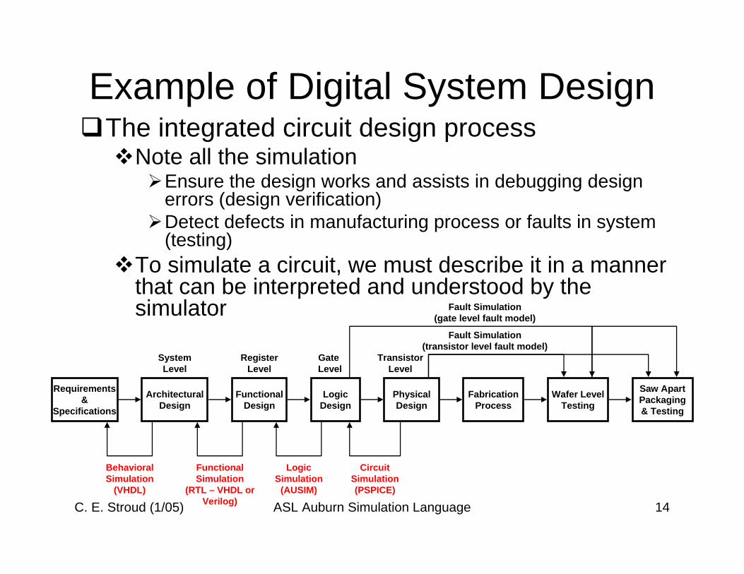
Example of Digital System DesignThe integrated circuit design process
Note all the simulationEnsure the design works and assists in debugging design errors (design verification)Detect defects in manufacturing process or faults in system (testing)
To simulate a circuit, we must describe it in a manner that can be interpreted and understood by the simulator
Requirements&
Specifications
ArchitecturalDesign
FunctionalDesign
PhysicalDesign
Saw ApartPackaging& Testing
Wafer LevelTesting
FabricationProcess
LogicDesign
LogicSimulation
(AUSIM)
CircuitSimulation(PSPICE)
FunctionalSimulation
(RTL – VHDL orVerilog)
BehavioralSimulation
(VHDL)
SystemLevel
Fault Simulation(transistor level fault model)
Fault Simulation(gate level fault model)
RegisterLevel
Gate Level
TransistorLevel
C. E. Stroud (1/05) ASL Auburn Simulation Language 15
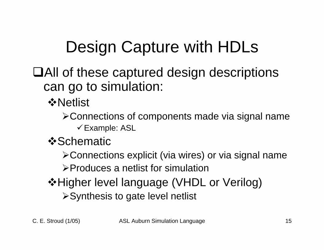
Design Capture with HDLsAll of these captured design descriptions can go to simulation:
NetlistConnections of components made via signal name
Example: ASL
SchematicConnections explicit (via wires) or via signal nameProduces a netlist for simulation
Higher level language (VHDL or Verilog)Synthesis to gate level netlist
C. E. Stroud (1/05) ASL Auburn Simulation Language 16
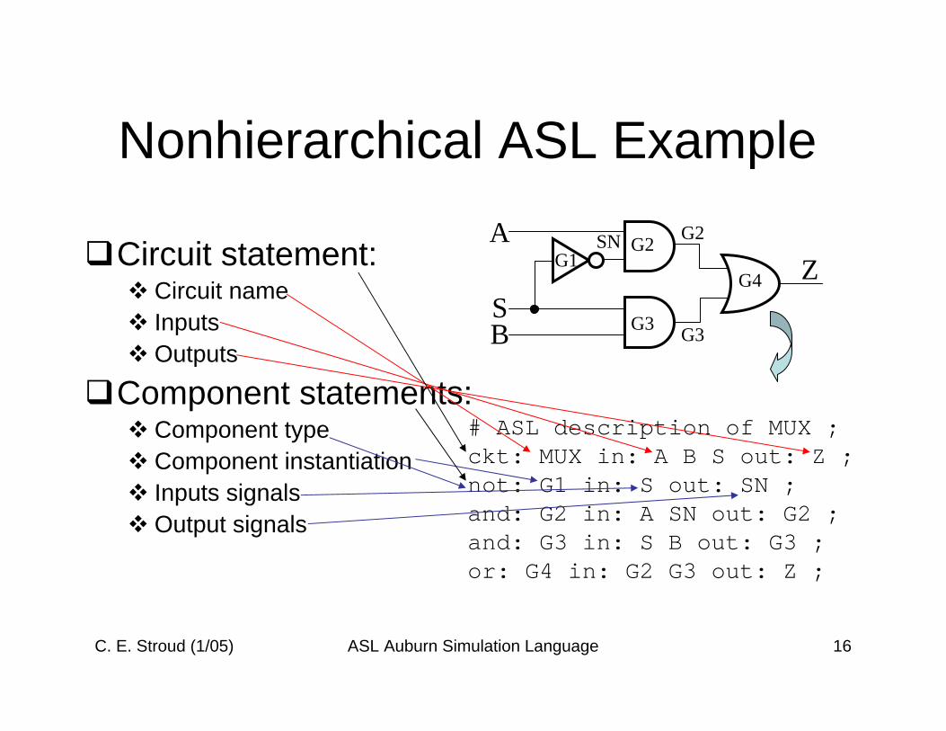
Nonhierarchical ASL Example
Circuit statement:Circuit nameInputsOutputs
Component statements:Component typeComponent instantiationInputs signalsOutput signals
ZS
A
B
G1G2
G3
G4
SN G2
G3
# ASL description of MUX ;ckt: MUX in: A B S out: Z ;not: G1 in: S out: SN ;and: G2 in: A SN out: G2 ;and: G3 in: S B out: G3 ;or: G4 in: G2 G3 out: Z ;
C. E. Stroud (1/05) ASL Auburn Simulation Language 17
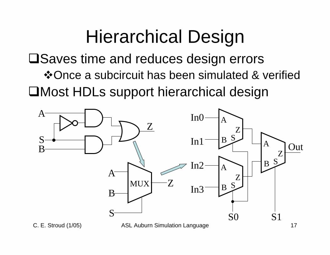
Hierarchical DesignSaves time and reduces design errors
Once a subcircuit has been simulated & verifiedMost HDLs support hierarchical design
ZS
A
B
MUX
S
A
BZ
S
A
BZ
S
A
BZ
S
A
BZ
In0
In1
In2
In3
S0 S1
Out
C. E. Stroud (1/05) ASL Auburn Simulation Language 18
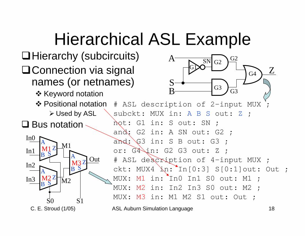
Hierarchical ASL ExampleHierarchy (subcircuits)Connection via signal names (or netnames)
Keyword notationPositional notation
Used by ASL
Bus notation
ZS
A
B
G1G2
G3
G4
SN G2
G3
# ASL description of 2-input MUX ;subckt: MUX in: A B S out: Z ;not: G1 in: S out: SN ;and: G2 in: A SN out: G2 ;and: G3 in: S B out: G3 ;or: G4 in: G2 G3 out: Z ;# ASL description of 4-input MUX ;ckt: MUX4 in: In[0:3] S[0:1]out: Out ;MUX: M1 in: In0 In1 S0 out: M1 ;MUX: M2 in: In2 In3 S0 out: M2 ;MUX: M3 in: M1 M2 S1 out: Out ;
In0
In1
In2
In3
S0 S1
Out
M1
M2
ZS
A
BM1 Z
ZS
A
BM2 Z
ZS
A
BM3 Z
C. E. Stroud (1/05) ASL Auburn Simulation Language 19
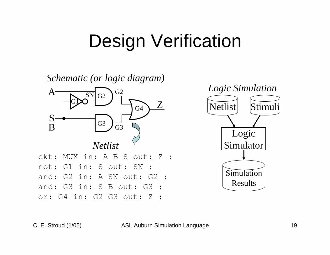
Design Verification
Schematic (or logic diagram)
Netlistckt: MUX in: A B S out: Z ;not: G1 in: S out: SN ;and: G2 in: A SN out: G2 ;and: G3 in: S B out: G3 ;or: G4 in: G2 G3 out: Z ;
Logic Simulation
ZS
A
B
G1G2
G3
G4
SN G2
G3
Netlist Stimuli
SimulationResults
LogicSimulator
C. E. Stroud (1/05) ASL Auburn Simulation Language 20
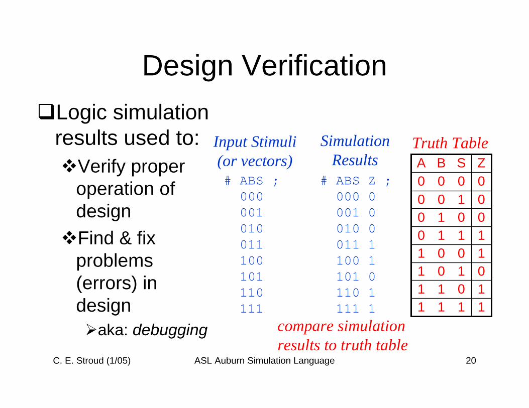
Design VerificationLogic simulation results used to:
Verify proper operation of designFind & fix problems (errors) in design
aka: debugging
# ABS ;000001010011100101110111
Input Stimuli(or vectors)
SimulationResults
# ABS Z ;000 0001 0010 0011 1100 1101 0110 1111 1
compare simulationresults to truth table
1110100101011011
1
100B
010000
1
0A
11
00ZS
Truth Table
C. E. Stroud (1/05) ASL Auburn Simulation Language 21
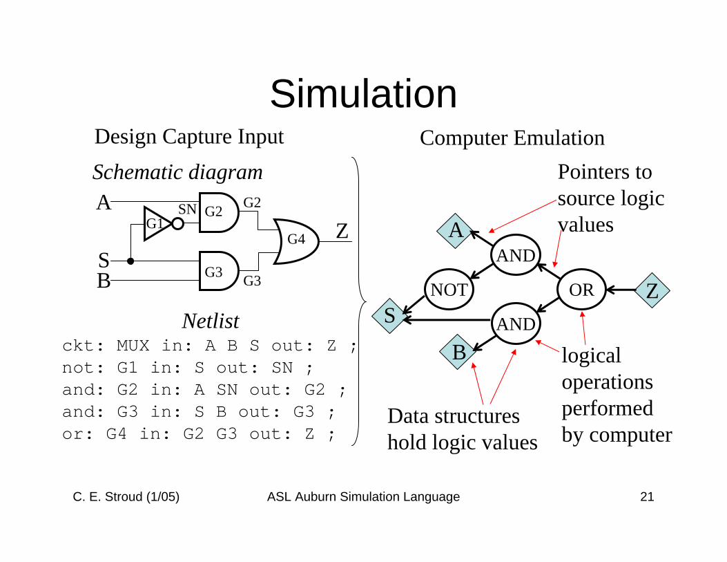
Simulation
Schematic diagram
Netlistckt: MUX in: A B S out: Z ;not: G1 in: S out: SN ;and: G2 in: A SN out: G2 ;and: G3 in: S B out: G3 ;or: G4 in: G2 G3 out: Z ;
ZS
A
B
G1G2
G3
G4
SN G2
G3 NOT
AND
AND
OR
A
B
ZS
Data structureshold logic values
Pointers tosource logicvalues
logicaloperationsperformedby computer
Design Capture Input Computer Emulation
C. E. Stroud (1/05) ASL Auburn Simulation Language 22
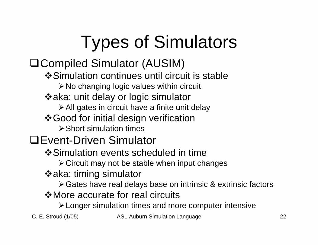
Types of SimulatorsCompiled Simulator (AUSIM)
Simulation continues until circuit is stableNo changing logic values within circuit
aka: unit delay or logic simulatorAll gates in circuit have a finite unit delay
Good for initial design verificationShort simulation times
Event-Driven SimulatorSimulation events scheduled in time
Circuit may not be stable when input changesaka: timing simulator
Gates have real delays base on intrinsic & extrinsic factorsMore accurate for real circuits
Longer simulation times and more computer intensive
C. E. Stroud (1/05) ASL Auburn Simulation Language 23
Audits for Common ProblemsUsually part of CAD tool
Schematic captureSimulator (AUSIM)
AUSIM audits for potential design errorsUnconnected gate inputsMultiple gates driving same net
AUSIM does not support tri-state or bi-directional busses
Subcircuit statement and instantiation have different number of inputs and/or outputs
Configuration bits in advanced versions of AUSIM
C. E. Stroud (1/05) ASL Auburn Simulation Language 24
Other AUSIM AuditsDuplicate names for:
Gates, inputs, outputs, and configuration bitsReserved characters (#, _, ;) in namesMultiple or missing CKT: statements in ASL fileCKT: statement(s) in library file
Only SUBCKT: statements allowed in .lib fileMissing IN: keyword after circuit or component nameSome rare errors
Incorrect number of inputs to inverter, flip-flop, latch or multiplexerConfiguration bits for gates (should not be any)
includes all elementary logic gates and functional modelsNet names too long
Before hierarchical flattening (so not too useful)Current length is 75 characters
C. E. Stroud (1/05) ASL Auburn Simulation Language 25
AUSIM FilesAll all input and output files are ASCII textAny text editor can be used to create input files
Be sure to save as text fileWhen using default file names be sure to delete .txt suffix from some eiditors (like NotePad) before executing AUSIM
Example: change name.asl.txt to name.asl
Be careful when using PC editore to create files and then running AUSIM on UNIX
To remove DOS control characters type the following command line (example for ASL only):
dos2unix name.asl name.aslUse same command with appropriate file suffix for other input files as needed
AUSIM checks for missing input files
C. E. Stroud (1/05) ASL Auburn Simulation Language 26
AUSIM Input Files (default names)Both logic and fault simulation need
ASL (name.asl)Library file (name.lib) – ASL file containing subcircuit descriptions
Workstation version of AUSIM needs for the .lib filean empty file or file with a valid comment will do
Configuration bit file (name.con) if CKT: statement has CON: keyword and list of config bit inputs
Logic simulation onlyInput vector file (name.vec)Optional: internal node file (name.nod) to monitor internal nodes
Fault simulation onlySimulation results file (name.out)
Generated by AUSIM during logic simulation (simul8 command)Fault list (name.flt) – list of faults to be emulated
Can be generated by AUSIM (fltgen or bftgen commands)
C. E. Stroud (1/05) ASL Auburn Simulation Language 27
AUSIM Output Files (default names)General files
Flattened ASL (name.fas)Flattened ASL description produced by keepfas command
Circuit audit (name.aud)Circuit statistics produced by audit command
Nets file (name.net)Lexicon ordered list of nets in data structures produced by nets command
Logic simulation filesSimulation results (name.out)
Produced by logic simulation simul8 command
C. E. Stroud (1/05) ASL Auburn Simulation Language 28
AUSIM Output Files (default names)Fault simulation files by produced fault simulation commands
Detected fault list (name.det)Includes vector and primary output where fault is first detected
Undetected fault list (name.udt)Potentially detected fault list (name.pdt)
Includes total number of vectors for which fault is potentially detectedThese faults also written to .udt file since they are only potentially detected
Oscillation fault list (name.osc)For serial fault simulation onlyContains faults that produce oscillations in circuit
Recall that AUSIM is a compiled simulatorFault detection profile (name.pro)
Give number of faults detected for vector set on a per vector and cumulative basis – produced by fltpro command
C. E. Stroud (1/05) ASL Auburn Simulation Language 29
AUSIM Fault List FileFault simulation requires a list of faults to be emulated
Detected fault list (name.det)Includes vector and primary output where fault is first detected
Undetected fault list (name.udt)Potentially detected fault list (name.pdt)
Includes total number of vectors for which fault is potentially detectedThese faults also written to .udt file since they are only potentially detected
Oscillation fault list (name.osc)For serial fault simulation onlyContains faults that produce oscillations in circuit
Recall that AUSIM is a compiled simulatorFault detection profile (name.pro)
Give number of faults detected for vector set on a per vector and cumulative basis – produced by fltpro command
C. E. Stroud (1/05) ASL Auburn Simulation Language 30
Control FileSpecifies file names
Default names can be specified withdefault name
Where name is common prefix for all filesDefault names overridden for any file withsuffix new_file_name
Where suffix is the default for a given file typeExample: out slop.txt
Specifies simulation results to be written to slop.txtinstead of name.out
C. E. Stroud (1/05) ASL Auburn Simulation Language 31
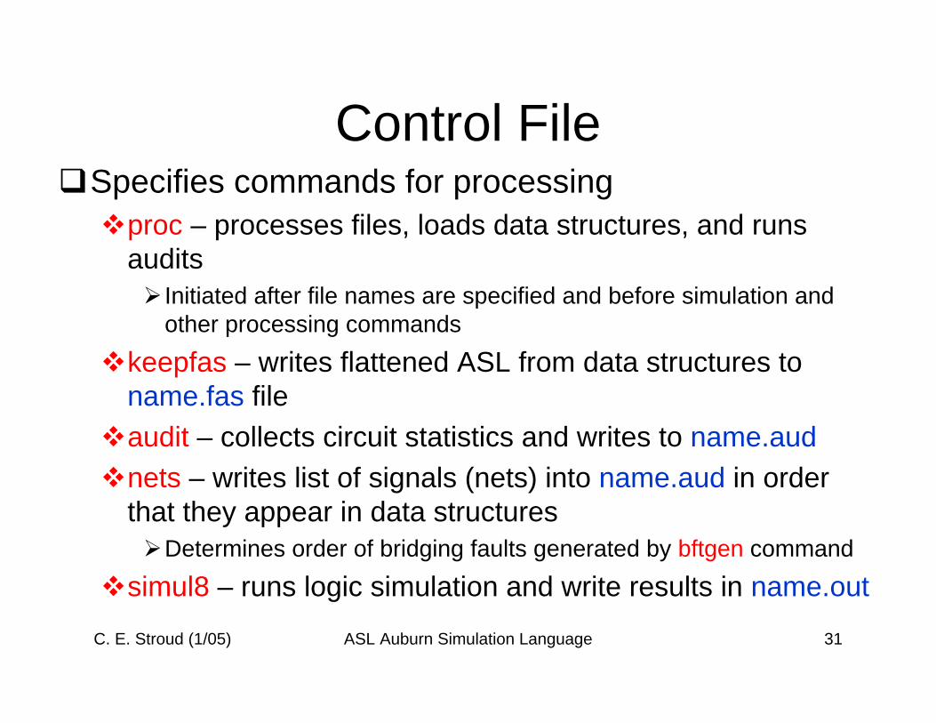
Control FileSpecifies commands for processing
proc – processes files, loads data structures, and runs audits
Initiated after file names are specified and before simulation and other processing commands
keepfas – writes flattened ASL from data structures to name.fas fileaudit – collects circuit statistics and writes to name.audnets – writes list of signals (nets) into name.aud in order that they appear in data structures
Determines order of bridging faults generated by bftgen command
simul8 – runs logic simulation and write results in name.out
C. E. Stroud (1/05) ASL Auburn Simulation Language 32
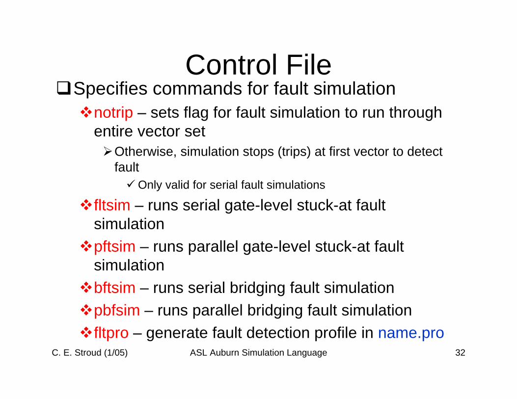
Control FileSpecifies commands for fault simulation
notrip – sets flag for fault simulation to run through entire vector set
Otherwise, simulation stops (trips) at first vector to detect fault
Only valid for serial fault simulations
fltsim – runs serial gate-level stuck-at fault simulationpftsim – runs parallel gate-level stuck-at fault simulationbftsim – runs serial bridging fault simulationpbfsim – runs parallel bridging fault simulationfltpro – generate fault detection profile in name.pro
C. E. Stroud (1/05) ASL Auburn Simulation Language 33
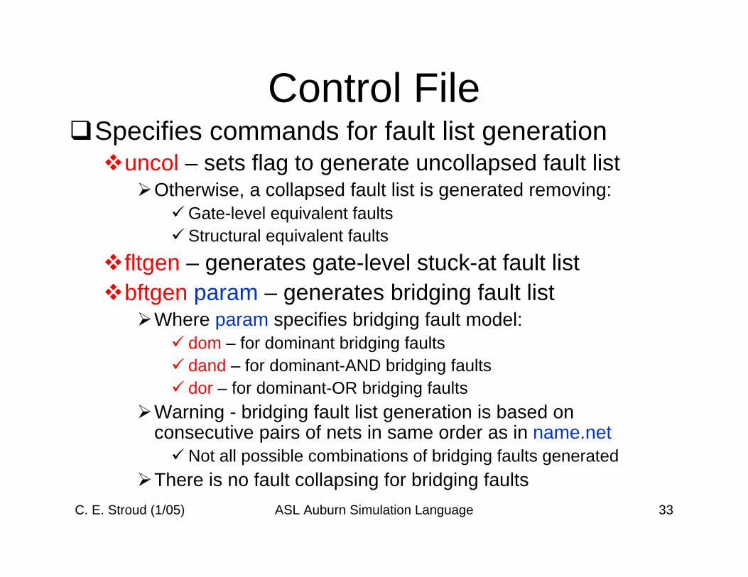
Control FileSpecifies commands for fault list generation
uncol – sets flag to generate uncollapsed fault listOtherwise, a collapsed fault list is generated removing:
Gate-level equivalent faultsStructural equivalent faults
fltgen – generates gate-level stuck-at fault listbftgen param – generates bridging fault list
Where param specifies bridging fault model:dom – for dominant bridging faultsdand – for dominant-AND bridging faultsdor – for dominant-OR bridging faults
Warning - bridging fault list generation is based on consecutive pairs of nets in same order as in name.net
Not all possible combinations of bridging faults generatedThere is no fault collapsing for bridging faults
C. E. Stroud (1/05) ASL Auburn Simulation Language 34
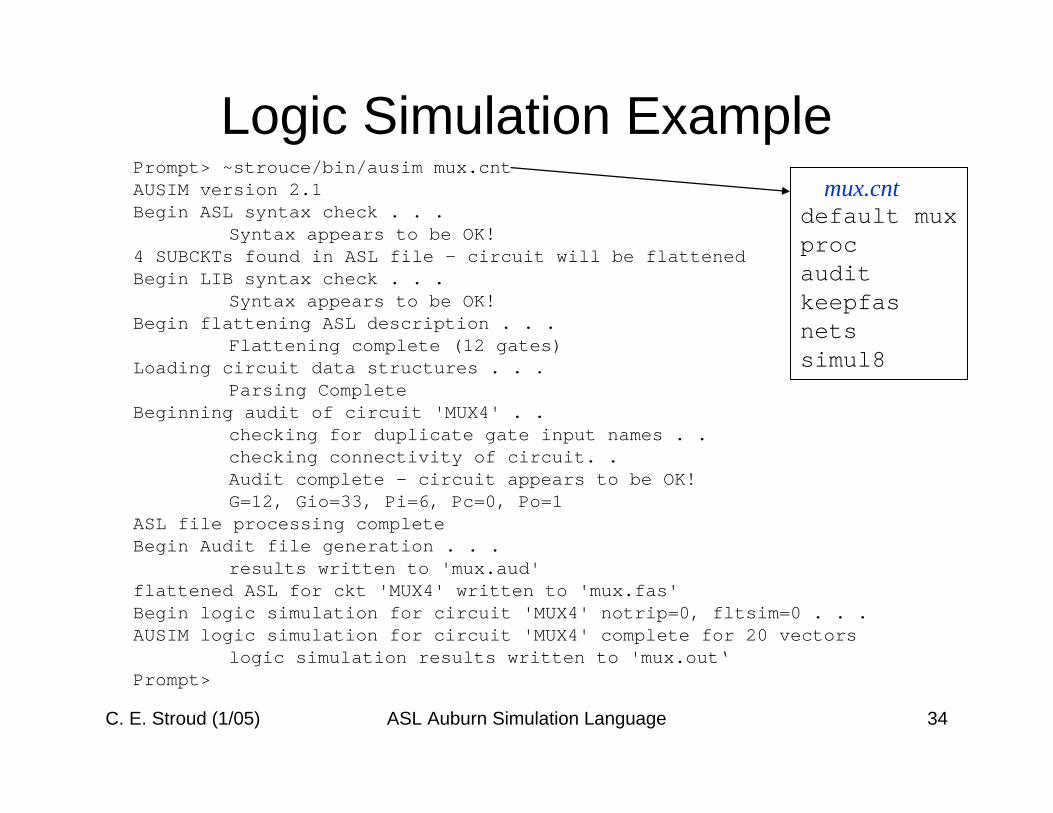
Logic Simulation Examplemux.cnt
default muxprocauditkeepfasnetssimul8
Prompt> ~strouce/bin/ausim mux.cntAUSIM version 2.1Begin ASL syntax check . . .
Syntax appears to be OK!4 SUBCKTs found in ASL file - circuit will be flattenedBegin LIB syntax check . . .
Syntax appears to be OK!Begin flattening ASL description . . .
Flattening complete (12 gates)Loading circuit data structures . . .
Parsing CompleteBeginning audit of circuit 'MUX4' . .
checking for duplicate gate input names . .checking connectivity of circuit. .Audit complete - circuit appears to be OK!G=12, Gio=33, Pi=6, Pc=0, Po=1
ASL file processing completeBegin Audit file generation . . .
results written to 'mux.aud'flattened ASL for ckt 'MUX4' written to 'mux.fas'Begin logic simulation for circuit 'MUX4' notrip=0, fltsim=0 . . .AUSIM logic simulation for circuit 'MUX4' complete for 20 vectors
logic simulation results written to 'mux.out‘Prompt>