Embed Size (px)
Citation preview
1 Copyright © #### by ASME
Proceedings of DETC’97:ASME DESIGN ENGINEERING TECHNICAL CONFERENCES
SEPTEMBER 14-17, 1997 -- SACRAMENTO, CALIFORNIA
DETC97/DFM-4352
A CASE STUDY IN MULTI-DISCIPLINARY DISTRIBUTED COLLABORATIVE DESIGN
Richard Riesenfeld Russell FishSamuel Drake
Department of Computer Science University of Utah
ABSTRACT
Researchers at the University of NorthCarolina at Chapel Hill and the University ofUtah participated in a collaborative, remote,rapid design and manufacturing experiment.Several domain experts at widely distributedgeographical locations worked on achallenging multi-disciplinary designproblem producing a rugged, compact andlight-weight housing for a Video See-Through Head-Mounted Display to be usedin image-guided surgical procedures. Thiswas used as a case study to validate andmotivate ongoing research in a distributedengineering design and manufacturingsystem.
The hypothesis was that Net-based use of ahighly supportive integrated, collaborativedesign and manufacturing environment woulddramatically expedite the design andmanufacturing process. Using the alreadyexisting Alpha_1 design and manufacturingenvironment as a platform, we embarked on aproject to collapse the normal six-monthcycle of design and prototype iterations into asingle three-week period of collaborativedesign. The lessons learned demonstrate thepotential success of the hypothesis, and alsoprovide a basis for further research into toolsand environments needed to supportintegrated collaborative design, engineering,and manufacture.
We discuss the results of the experiment,application of the existing distributed designsystem, the supporting system architecture,and possible future research issues brought tolight by the experiment.
Keywords: CAD/CAM, Collaborative Design,Multi-disciplinary Design, DistributedDesign
PROBLEM STATEMENT: THE EFFECT OF AMULTI-DISCIPLINARY COLLABORATIVEDISTRIBUTED DESIGN ENVIRONMENT ON THEDESIGN PROCESS
Researchers from the University of NorthCarolina at Chapel Hill and from the University of Utahparticipated in a study of the design process in acollaborative, distributed engineering design andmanufacturing environment. Working at widelydistributed geographical locations, experts from severalengineering disciplines collaborated on the rapid designand manufacture of a rugged, compact and light-weight housing for a Video See-Through Head-MountedDisplay developed at UNC for use in image-guidedsurgical procedures. Our 8-10 member team collapsed thenormal six-month cycle of design and prototype iterationsinto a single three-week period of collaborative design.This housing design experiment serves as a case study forour analysis of the effects of multi-disciplinarycollaboration, and specifically rapid collaboration at adistance, on the design process in a highly supportivedesign environment.
2 Copyright © #### by ASME
Collaborative design is defined as the activity ofdesigning through the interaction of designers and theenvironment (Saad and Maher, 1996). Our researchobjective for the collaborative experiment was todetermine how the design and manufacturing processitself was affected by the environment we constructedand the design goals we set. Aspects of the process underinvestigation fall in three broad categories: issues relatingto the interactions of design team members in thecollaborative environment, issues associated with theevolution of the design itself and the systems supportingit, and issues relating to manufacture and the systemssupporting it. Our research addressed problems arisingfrom competing and sometimes contradictory forces atwork in these three areas of distributed, integratedcollaboration.
As far as the collaborative environment wasconcerned, we wanted to investigate the ability ofgeographically dispersed team members from differentdisciplines to work together. A collaborative system thatsupports team work at the same time in different places isknown as a synchronous distributed system (Saad andMaher, 1996). Believing that one is in some physicalenvironment where one is not requires a sense ofpresence or a willingness to suspend disbelief. Whenparticipants are at remote locations, a medium ofcommunication is required to convey this sense ofpresence, known as telepresence (Steuer, 1992). In ourexperiment telepresence was provided by video-link andthe InterNet. Problems associated with this collaborativeenvironment include:
• experts from different disciplines and atdifferent geographical sites, who do not necessarily knoweach other, have to use telecommunication and designtools with which all team members are not necessarilyfamiliar
• team members have to become familiar witheach others’ fields to the point of being able tounderstand the impact of other disciplines on their own
• the experimental environment exposes certainlimits of current experimental CAD systems: while use ofthe InterNet makes it possible for team members atdifferent sites to view the same CAD model,communication protocols do not yet exist to allow bothteams to make simultaneous changes to the model;another limitation is that viewing can at the moment becontrolled either locally (at each client site) or globally(from the server), but switches from one control mode toanother are not possible during a collaborative session.
An objective relating to the evolution of thedesign was to determine the design tools required, as wellas the communications capabilities needed to support theuse of a CAD system over the InterNet and via tele-video. Problems in this area:
• the experimental environment exposes certainlimits of current experimental CAD systems: while use ofthe InterNet makes it possible for team members atdifferent sites to view the same CAD model,communication protocols do not yet exist to allow bothteams to make simultaneous changes to the model;another limitation is that viewing can at the moment becontrolled either locally (at each client site) or globally(from the server), but switches from one control mode toanother are not possible during a collaborative session
Issues relating to manufacturing revolved aroundthe integration of design and manufacture, so thatmanufacturing considerations would influence the designat all times:
• time pressures require that the normal six-monthcycle of design, prototype, and iterations be collapsedinto a single three-week concurrent design period
• despite the reduced time period, a reliable,high-quality product has to be manufactured
• the manufacturing process has to allow formaking several dozen additional copies
The goal of our paper is to discuss each of these
problem areas as they relate to the evolving designprocess. Unlike collaborative design reviews that focusprimarily on evaluation of the final model and product,we discuss the effects of the integrated, distributed, rapiddesign and manufacturing environment on the structureof the design and design process themselves. Ourdiscussion of this process will be grouped under the threecategories delineated above, namely the design team atwork in the integrated collaborative environment, designissues, and manufacturing issues.
1. The Design Process and the Integrated Design andManufacturing Collaboration Environment
A research goal of our experiment was toinvestigate the effect of an integrated collaborativedesign environment on the design process as it relates tothe historical gap between design and manufacture, and
3 Copyright © #### by ASME
also to the separation among different design disciplines,for example video-optical and mechanical design.Although computer aided design (CAD) and computeraided manufacture (CAM) have in recent years speededup product design and manufacture, the historicaldivision between the design engineer at his drafting deskand the manufacturing engineer in the machine shop hasnot yet been overcome. When putting a vision on paper,designers often fail to consider cost or manufacturability,while manufacturers’ modifications violate the designersvision. Costly and time-consuming design iterations arerequired to bridge the gap between the designer’s intentand manufacturing realities.
Traditionally the design to manufacture processfor this kind of product would have had a linear structurewith three stops. The optical design would have beenpassed to a mechanical engineer, who would have laidout an encasement. This design would then have beengiven to a manufacturing engineer.
After putting together a proof of concept designusing off the shelf components, researchers at UNCdecided that a custom designed and built casing would benecessary to meet the design requirements. Ourcollaborative experiment was driven by UNC’s need for acasing, as well as by Utah’s interest in investigatingwhether the design and manufacturing environment couldbe enhanced by collaboration integrating the resources ofdifferent engineering disciplines and by the use ofresearch-level design tools. Using Utah’s Alpha_1research test bed, our collaborative effort would integratedesign considerations from the video-optical, electro-mechanical and manufacturing disciplines into the designprocess of the VST-HMD instrument.
While providing the benefits of an integratedcollaborative environment, our experiment’s use of theNet would allow researchers to remain in their localenvironments where they are most productive andeffective, avoiding the disruption of co-location. Eventhough the designers on our project were geographicallyseparated by the width of a continent,telecommunications devices allowed us to interact face toface in real time. We used a dedicated T-1 compressedvideo-conference link between UNC and Utah. Aparallel design channel was provided by workstationcomputers at both ends, linked through the InterNet andrunning the Alpha_1 research test bed softwaredeveloped at Utah. Alpha_1 has a client server
architecture that lends itself to collaboration at a distance.The workstations at UNC and Utah displayed thecomputer model of the design to participants duringdesign discussions. Team members at different siteswere able to view the same CAD model, and each sitehad independent control of its own viewing. This abilityenabled optics experts and mechanical engineers, forexample, to examine different features of the model atthe same time. If distributed teams needed to look at thesame orientation of the model simultaneously, thetelephone or video link was used to ensure that theviewing was coordinated. When changes needed to bemade to the model during collaborative sessions, the Utahteam retained control of modifying the model. Existingcommunications protocols require that control remains atone of the remote sites since protocols for switchingcontrol do not yet exist. As the model evolved in real-time, the incorporated changes were immediatelypropagated from the server to clients at all sites via theInterNet link. By using telecommunication facilities tocompensate for the lack of switching protocols, we werenevertheless able to successfully integrate the entiredesign-to-manufacture process.
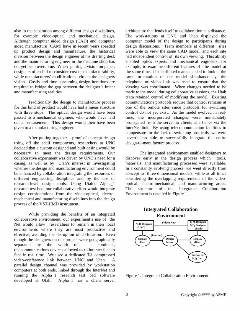
The integrated environment enabled designers todiscover early in the design process which tools,materials, and manufacturing processes were available.In a constantly evolving process, we went directly fromconcept to three-dimensional models, while at all timesconsidering the overlapping requirements of the video-optical, electro-mechanical, and manufacturing areas.The structure of the Integrated CollaborationEnvironment is detailed in Figure 1.
Integrated CollaborationEnvironment
V-O Designer (UNC)
E-M DesignerMfg Designer
(Utah)
Display client
Display client
DesignServer
AdvancedMfg Lab
(Video Net)
(Internet)
Figure 1. Integrated Collaboration Environment
4 Copyright © #### by ASME
2. The Design Process and the Evolution of theDesign
Our design goal in collaboration with the UNCgroup was to provide housing specifications for anextremely light-weight, rugged, compact Video See-Through Head-mounted Display (VST - HMD):UNC’s VST - HMD project is aimed at creating a deviceto be used during medical augmented-reality procedures.Augmented reality superimposes virtual reality displaysonto a real-world environment. Information obtainedfrom diagnostic tools such as ultrasound is superimposedon the surgeon’s actual view of the patient duringsurgery. In the diagnosis of breast cancer, for example,the video see-through feature of the VST - HMD willcapture a portion of the surgeon’s visual field with twocameras and pass it through stereo displays, one for eacheye. Software and special purpose computer hardwarecreated by UNC will allow information about what’shappening inside the patient, as relayed by real-timeultra-sound imagery, to be superimposed as if it werebeing seen directly inside the patient. With the aid of thistechnology, a more accurate diagnosis of diseases such asbreast cancer through ultra-sound image-guided needlebiopsies will be possible.
UNC’s optics design goal was to provide a unitwith an optically correct overlay. In earlier video displayunits available to surgeons performing image-guidedprocedures, the depth perception was off by 6 to 8 inches.This was caused by a discrepancy between the opticalpath lengths from the primary mirror to the user’s eyeiris, and from the primary mirror to the camera iris.
By the onset of our project, UNC had alreadydeveloped an initial video-optical design in which theoptical path was folded to ensure equal optical pathlengths. The design incorporates a newly availablecommercial miniature video camera and displaycomponents. In addition to ensuring correct depthperception, the design was based on requirements arisingfrom the product’s intended use during surgery, andincluded considerations such as the intra-ocular distanceand the inclusion of a mechanism to adjust depthperception for individual users. In the ongoing evolutionof the design, we never migrated from the requirementsof an optically correct design. Although modifications
were made to accommodate design and manufacturingconsiderations, at each stage the working design was anoptically correct variant of the initial optical solution.The Alpha_1 modeling system was instrumental inmaintaining the optical constraints while mechanicaldesign considerations were being incorporated into thedesign.
Video-Optical Issues in the Evolution of the Design
At Utah our manufacturing and design goal wasto produce a compact, lightweight housing to hold thecomponents in place in accordance with the opticalsolution. Two parallel and sometimes conflictingconsiderations guided the design at this stage: thehousing had to be the smallest possible size while stillallowing for a configuration of components that conformsto the optical solution. The two main functions of thehousing are to protect the optical components and to holdthem in place. Accurate placement of the components iscritical to the optics, since small errors can affect theoptical path. Already at this early stage we solicitedinput from the manufacturing engineer about lightweightmaterials, and discovered that the shrinkage of moldedplastic upon cooling was another obstacle to beconsidered in the correct placement of the components. Inaddition to its main functions, the housing has to providea mechanism for the user to adjust the distance betweenthe eyes and the angle determining where the images willconverge. A major optical consideration that figured intothe housing design was the constraint imposed by theVST (video see-through) feature requiring equal opticalpath lengths from the primary mirror to the user’s eyeiris, and from the primary mirror to the camera iris, alongthe view-center rays. This configuration requires anangular distance similar to that of a computer monitor atarms length. In addition the unit should cause minimalobstruction of peripheral vision.
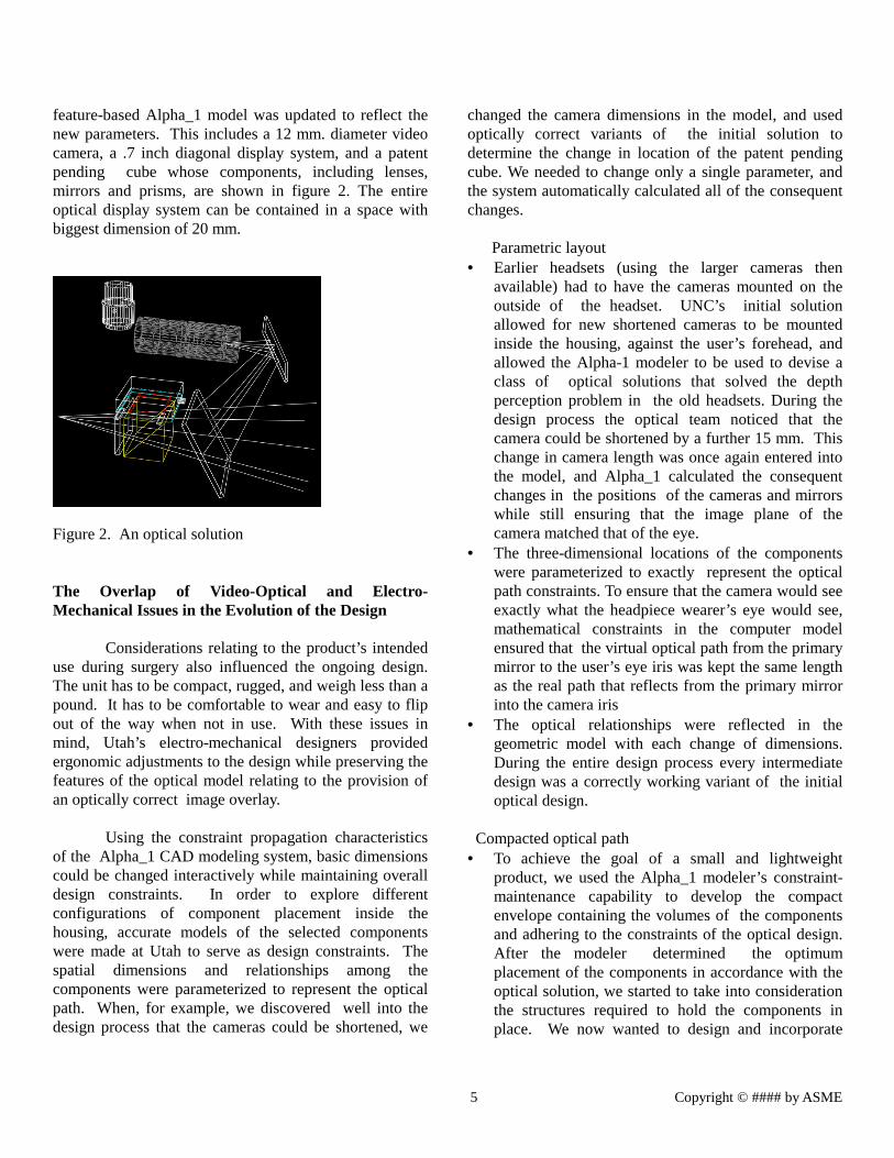
Figure 2 shows the preliminary layout ofcomponents in accordance with an optical solution thatprovided the starting point for the mechanical design.
Components required by the initial optical design hadalready been developed at the onset of the project. Afterthe collaborative process had already started, the teambecame aware that newer, smaller cameras than the onesin UNC’s initial design had become available. UNCincorporated this new technology in the design, and the
5 Copyright © #### by ASME
feature-based Alpha_1 model was updated to reflect thenew parameters. This includes a 12 mm. diameter videocamera, a .7 inch diagonal display system, and a patentpending cube whose components, including lenses,mirrors and prisms, are shown in figure 2. The entireoptical display system can be contained in a space withbiggest dimension of 20 mm.
Figure 2. An optical solution
The Overlap of Video-Optical and Electro-Mechanical Issues in the Evolution of the Design
Considerations relating to the product’s intendeduse during surgery also influenced the ongoing design.The unit has to be compact, rugged, and weigh less than apound. It has to be comfortable to wear and easy to flipout of the way when not in use. With these issues inmind, Utah’s electro-mechanical designers providedergonomic adjustments to the design while preserving thefeatures of the optical model relating to the provision ofan optically correct image overlay.
Using the constraint propagation characteristicsof the Alpha_1 CAD modeling system, basic dimensionscould be changed interactively while maintaining overalldesign constraints. In order to explore differentconfigurations of component placement inside thehousing, accurate models of the selected componentswere made at Utah to serve as design constraints. Thespatial dimensions and relationships among thecomponents were parameterized to represent the opticalpath. When, for example, we discovered well into thedesign process that the cameras could be shortened, we
changed the camera dimensions in the model, and usedoptically correct variants of the initial solution todetermine the change in location of the patent pendingcube. We needed to change only a single parameter, andthe system automatically calculated all of the consequentchanges.
Parametric layout• Earlier headsets (using the larger cameras then
available) had to have the cameras mounted on theoutside of the headset. UNC’s initial solutionallowed for new shortened cameras to be mountedinside the housing, against the user’s forehead, andallowed the Alpha-1 modeler to be used to devise aclass of optical solutions that solved the depthperception problem in the old headsets. During thedesign process the optical team noticed that thecamera could be shortened by a further 15 mm. Thischange in camera length was once again entered intothe model, and Alpha_1 calculated the consequentchanges in the positions of the cameras and mirrorswhile still ensuring that the image plane of thecamera matched that of the eye.
• The three-dimensional locations of the componentswere parameterized to exactly represent the opticalpath constraints. To ensure that the camera would seeexactly what the headpiece wearer’s eye would see,mathematical constraints in the computer modelensured that the virtual optical path from the primarymirror to the user’s eye iris was kept the same lengthas the real path that reflects from the primary mirrorinto the camera iris
• The optical relationships were reflected in thegeometric model with each change of dimensions.During the entire design process every intermediatedesign was a correctly working variant of the initialoptical design.
Compacted optical path• To achieve the goal of a small and lightweight
product, we used the Alpha_1 modeler’s constraint-maintenance capability to develop the compactenvelope containing the volumes of the componentsand adhering to the constraints of the optical design.After the modeler determined the optimumplacement of the components in accordance with theoptical solution, we started to take into considerationthe structures required to hold the components inplace. We now wanted to design and incorporate
6 Copyright © #### by ASME
space for the fixed fins and webs required to hold thecomponents in place. We also had to allow space forflexible components such as wires, which are notrepresented in any CAD models. Since we did nothave the specifications for these elements, but onlythe actual physical objects to work with, we resortedto a traditional process: “to-scale” modeling and theuse of calipers to determine component dimensions.During this stage designers assumed rotationalcamera symmetry in designing the fins and webs tohold it. At the end of this stage a compact yetmanufacturable and optically correct design for thecasing had been created.
Initial housing profile designed• Once we had a computer model of the housing, it was
evident that its exterior outline was very complicated.The manufacturing engineer contributed theimportant insight that all the components are thesame width across, except for the one mirror that waswider. A separate rectangular volume was added toprovide the required space for the mirror.
New optical requirement added• When UNC reviewed this design from an optical
point of view, they realized that their originalspecifications would result in a casing that would letin too much light. The casing was open in front sothat the view of the patient would not be obstructed.As a result of working in an integrated environment,they were able to use the feedback they received torequest a change to the housing profile to preventexterior light from getting in. In a solution arrived atjointly by the teams, we added a light baffle to thefront of the casing that would prevent most exteriorlight from getting in and yet cause minimalobstruction of the wearer’s view of the realenvironment. Without the close coordination ofmechanical and optical teams and the ability to viewthe model at every stage, this problem wouldprobably not have been discovered until after the firstpass through the manufacturing process.
Suspend casing from frame• Until this stage of the design, UNC’s initial optical
specifications required a separate, mirror-imageworking unit for the left and right eye. Ourmanufacturing engineer pointed out that there seemedto be no optical or electro-mechanical reason for the
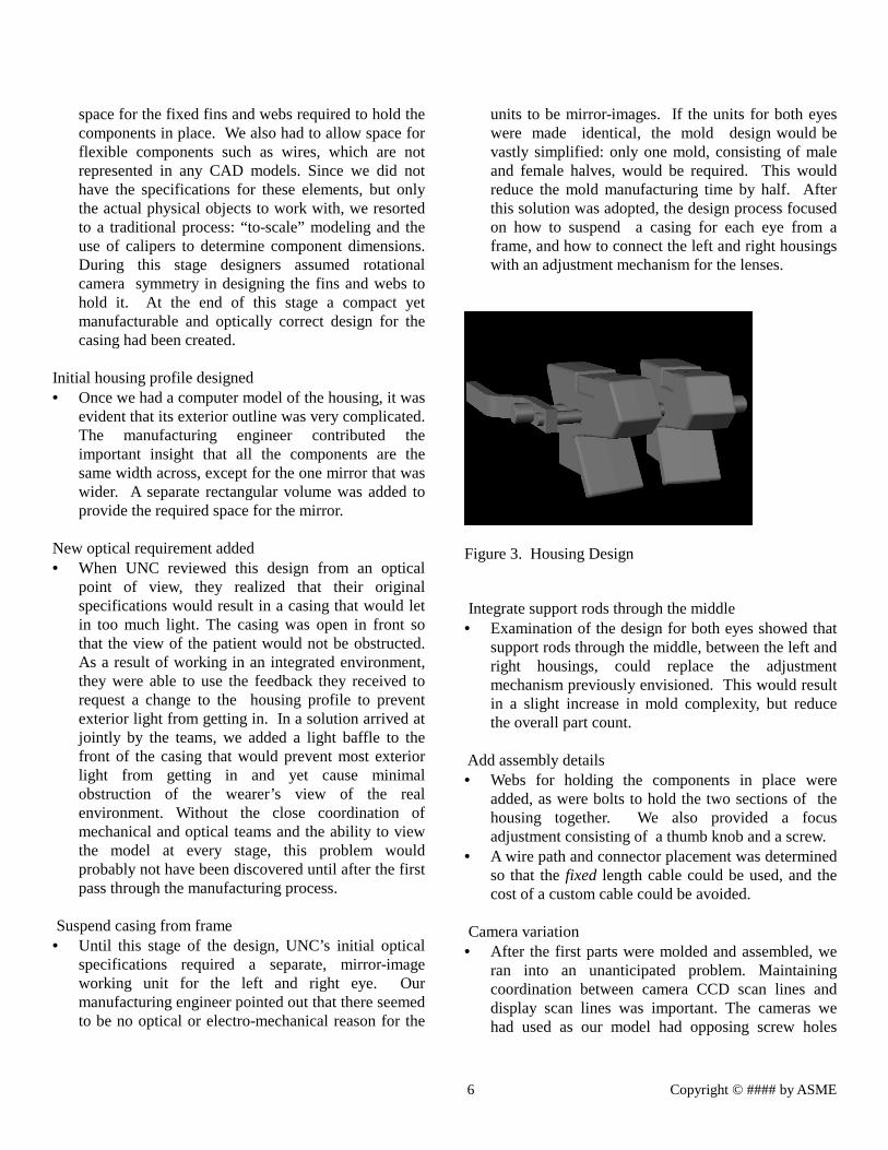
units to be mirror-images. If the units for both eyeswere made identical, the mold design would bevastly simplified: only one mold, consisting of maleand female halves, would be required. This wouldreduce the mold manufacturing time by half. Afterthis solution was adopted, the design process focusedon how to suspend a casing for each eye from aframe, and how to connect the left and right housingswith an adjustment mechanism for the lenses.
Figure 3. Housing Design
Integrate support rods through the middle• Examination of the design for both eyes showed that
support rods through the middle, between the left andright housings, could replace the adjustmentmechanism previously envisioned. This would resultin a slight increase in mold complexity, but reducethe overall part count.
Add assembly details• Webs for holding the components in place were
added, as were bolts to hold the two sections of thehousing together. We also provided a focusadjustment consisting of a thumb knob and a screw.
• A wire path and connector placement was determinedso that the fixed length cable could be used, and thecost of a custom cable could be avoided.
Camera variation• After the first parts were molded and assembled, we
ran into an unanticipated problem. Maintainingcoordination between camera CCD scan lines anddisplay scan lines was important. The cameras wehad used as our model had opposing screw holes
7 Copyright © #### by ASME
aligned with the CCD horizontals, so we createdholes in the mold aligned with those on the camera.However, later cameras did not repeat that alignment.That is, holding the cameras in that position led toangled scan lines, with each camera different. Thesolution required redesigning the mold to enable thecameras to rotate the required amount to align scanand display, and still be held in place.
3. The Design Process and Issues of Manufacture
A result of working in an integrated environmentwas that a continuous dialogue was maintained with themanufacturing engineer from the initial stage. While theoptical solution was still being refined, the manufacturingengineer was already considering materials and methodsthat would ensure a lightweight, compact, easilyreproducible product that would be manufacturablewithin the time constraints. Once a manufacturableelectro-mechanical solution had been reached, UNCreexamined it from an optics point of view, and furtheradjustments were made. The integrated collaborativeenvironment allowed all of these manufacturingconsiderations to feed back into the design processdespite the geographical separation between the differentengineering groups.
Material and manufacturing process choice
The two primary considerations that governedmanufacturing choices were the projected three-weekproduction time and the goal of producing several dozensof the unit. Materials and processes considered were thefollowing:• Machined metal has the advantage of being the most
straightforward and most accurate process;disadvantages are its weight and high unit cost.
• “Rapid Prototyping” plastic (STL, FDM) has theadvantage that no molds are needed and that theproducts are lightweight; disadvantages are that theprocess is less accurate and slower, and that theproduct is less rugged.
• Injection-molded plastic (ABS) was the winningchoice, since products are lighter and more ruggedthan those produced in the above-mentionedprocesses. Once the molds are machined, the cost permolded unit is low. The only negative associatedwith this process is the possibility of shrinkage—and
we hoped to contend with it by incorporating theanticipated shrinkage into the design.
• Once a manufacturable optically correct workingmodel had been achieved, the designers’communication with the manufacturing engineerprovided insights into the mold manufacturingprocess that fed back into the design process. Whiledesigning the mold, the manufacturing engineer hasto provide manufacturing details for removing theplastic product from the mold. The design was draft-angled to prevent it from sticking in a plastic ejectionmold, and ejector pin locations were worked into thedesign. Slots were made wider to improve the flowof plastic.
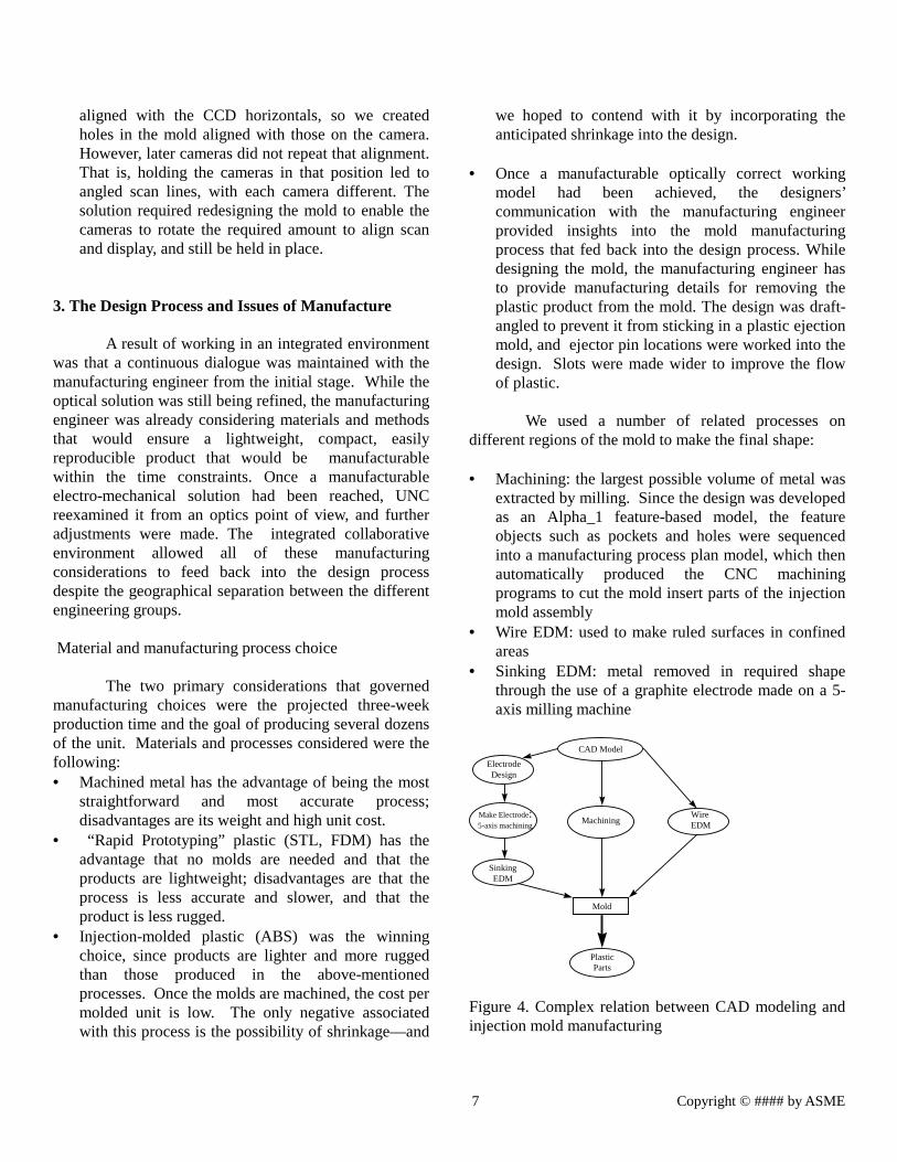
We used a number of related processes ondifferent regions of the mold to make the final shape:
• Machining: the largest possible volume of metal wasextracted by milling. Since the design was developedas an Alpha_1 feature-based model, the featureobjects such as pockets and holes were sequencedinto a manufacturing process plan model, which thenautomatically produced the CNC machiningprograms to cut the mold insert parts of the injectionmold assembly
• Wire EDM: used to make ruled surfaces in confinedareas
• Sinking EDM: metal removed in required shapethrough the use of a graphite electrode made on a 5-axis milling machine
CAD Model
ElectrodeDesign
Machining
Mold
WireEDM
PlasticParts
Make Electrode:5-axis machining
SinkingEDM
Figure 4. Complex relation between CAD modeling andinjection mold manufacturing
8 Copyright © #### by ASME
In each of these steps errors could occur thatcould affect the accuracy of the design so crucial to theoptics, but because of the integrated design environmentwe were able to address problems as we became aware ofthem. Figure 4 shows the hierarchical relation amongmodeling and manufacturing concerns.
The Overlap of Electro-Mechanical andManufacturing Design Issues
Simplified housing concept• Although the compact design was manufacturable,
the manufacturing engineer immediately suggestedthat the it could probably be simplified. At this stagethe casing had prismatic angles that would be hard tomake. After further discussion the electro-mechanical and manufacturing teams jointly decidedthat a flat-sided casing would fulfill all electro-mechanical and optical requirements, and machiningthe mold would be easier. A casing consisting of twoflat-bottomed pockets with different depths wasdecided upon.
At the end of this phase we had achieved a designthat represented a reconciliation of the interests of thethree engineering disciplines. We had moved from theconcept to a choice of components, to the analysis of ourgraphics modeler’s 3-D sketches, and on to a solid modelconforming to an optical solution. In the followingphases our dialogue continued to refine the product. Asdiscussed in the previous section, examination of thedesign after the left and right casings had been combinedshowed that support rods through the middle couldreplace the adjustment mechanism previously envisioned.This change was incorporated into the design of themold, slightly increasing its complexity, but reducing theoverall part count.
Assemblability and repeatability• Since at most several dozen units were to be
manufactured, we weighed the time that would besaved by easier and speedier assembly against thetime that would be lost in making the necessaryadjustments in the mold design. We decided thatassembly considerations were secondary to overalldesign and manufacturing time. Unfortunately, theproduct ended up being hard to assemble. Eventhough the webs were designed to hold the
components in place once the casing was assembled,they did not do so prior to assembly. Further, thecomponents slipped out of alignment as the twohalves of the casing were brought together.
After the assembly of a few units at UNC, wecollaboratively devised solutions to make assembly easierand assessed whether it would be necessary to make anew mold to incorporate the design changes. We decidedthat the current mold, processes, and materials wereadequate for our present production needs. Only if muchlarger quantities of the product had to be manufacturedwould it justify the cost of making the required changesto the mold.
Results
Despite the fact that we used relatively primitiveexisting tools -- tools not designed with the primarypurpose of working in a remote, distributed collaborativeenvironment -- we were successful in designing aworking product in only three weeks. There werehowever, several design features that had not beenincorporated into the first manufactured version of thecasing. Both the thumbscrew focus adjust and thei.p.d./convergence adjust are to be incorporated into thenext version of the casing. Other desirable traits, such aswebs to insure l.c.d. orientation, were not represented inthe computer model. These deficiencies can be directlyattributed to the three week cycle time. By using theclient server architecture to enable each site to have localcontrol over its viewing, valuable design time was savedby allowing each team to focus on the aspects of thedesign most pertinent to their expertise. On occasionswhen the design process required all teams to view thesame orientation of the model, the telephone or video linkprovided the necessary communication tools to directcoordinated viewing. By using the InterNet to propagatedesign changes from the server to the client sites, allteams continually had access to the latest changes in thedesign. The complexity of the overall design process and theintermediate derivative processes is not evident whenlooking at the finished product or even its “blueprints.”The resulting feature-based model captures the final stateof the design very well, but does not include earlierdesign alternatives.
9 Copyright © #### by ASME
The successful outcome of this collaboration hasserved to drive Alpha_1 development of a more completecollaborative engineering design environment. Anobvious development required is for control protocolsthat will allow a peer to peer rather than a client serverarchitecture.
Conclusions and Future Research Remote collaborative design is not only exciting, butreal. Our experience has shown that experts in multipleengineering disciplines working in a distributed,collaborative design and manufacturing effort canproduce a viable and useful product: the VST-HMD hasmade a contribution to the UNC ultrasound project. In addition to cutting down on costs related toproduction and manufacturing time, the remote,distributed collaborative environment can drasticallyreduce travel and consultation overheads. However, our experiment brought the need for newdesign and communication tools to light.Communication between the various remotely locatedteam members proved the most difficult challenge.Spontaneous brain storming, possible with co-locatedteams, was not possible, since the video teleconferencinghad to be scheduled in advance. Some spontaneity waspossible when participants discussed reviews andmodifications by phone while each discussion participantran the modeling system. Several researchers found thevoice and video lag time during teleconferencingdetrimental to the spontaneity of the design process.These are areas that still need considerable work beforethe collaborative design environment becomes a practicaltool. Insights about the structure of the design processitself will be beneficial in future collaborations. Earlyintroduction of all interests including manufacturingseems beneficial. The requirements of each relevantengineering discipline should be actively expressed andrepresented throughout the design process.
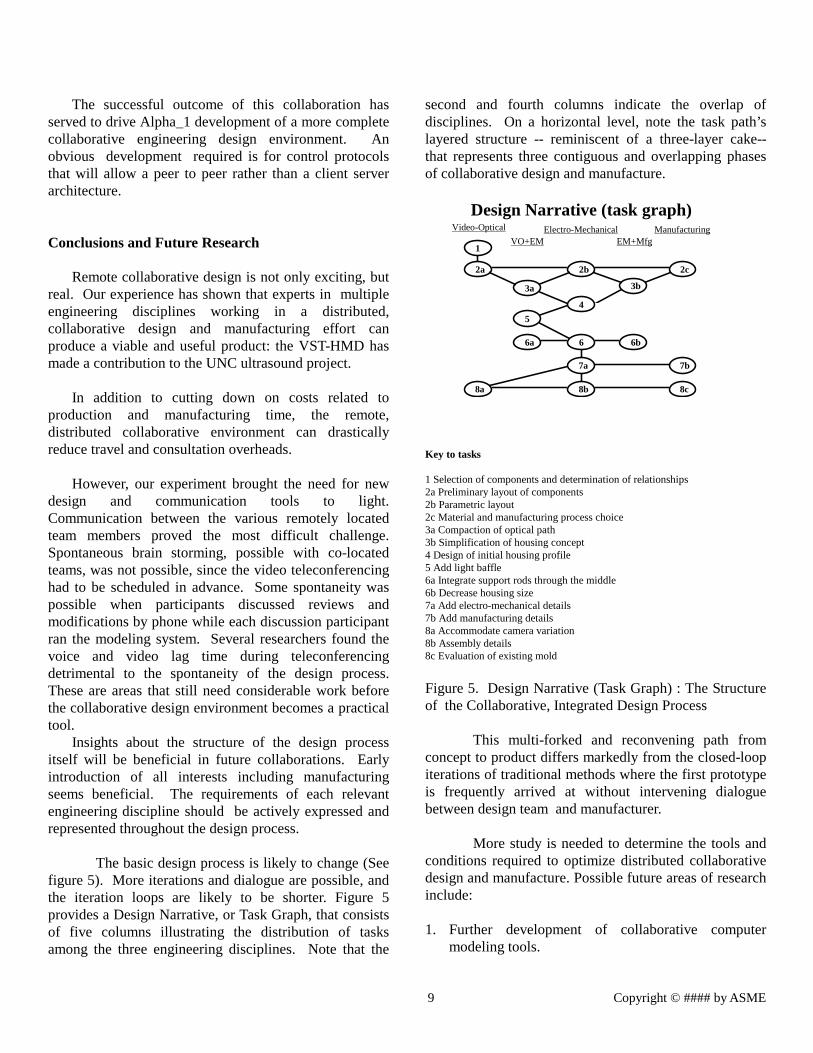
The basic design process is likely to change (Seefigure 5). More iterations and dialogue are possible, andthe iteration loops are likely to be shorter. Figure 5provides a Design Narrative, or Task Graph, that consistsof five columns illustrating the distribution of tasksamong the three engineering disciplines. Note that the
second and fourth columns indicate the overlap ofdisciplines. On a horizontal level, note the task path’slayered structure -- reminiscent of a three-layer cake--that represents three contiguous and overlapping phasesof collaborative design and manufacture.
Design Narrative (task graph)Video-Optical
VO+EMElectro-Mechanical
EM+MfgManufacturing
1
2a 2b 2c
3a 3b
4
5
6a 6 6b
7a 7b
8a 8b 8c
Key to tasks
1 Selection of components and determination of relationships2a Preliminary layout of components2b Parametric layout2c Material and manufacturing process choice3a Compaction of optical path3b Simplification of housing concept4 Design of initial housing profile5 Add light baffle6a Integrate support rods through the middle6b Decrease housing size7a Add electro-mechanical details7b Add manufacturing details8a Accommodate camera variation8b Assembly details8c Evaluation of existing mold
Figure 5. Design Narrative (Task Graph) : The Structureof the Collaborative, Integrated Design Process
This multi-forked and reconvening path fromconcept to product differs markedly from the closed-loopiterations of traditional methods where the first prototypeis frequently arrived at without intervening dialoguebetween design team and manufacturer.
More study is needed to determine the tools andconditions required to optimize distributed collaborativedesign and manufacture. Possible future areas of researchinclude:
1. Further development of collaborative computermodeling tools.
10 Copyright © #### by ASME
2. Improvement of video communication tools.3. Aspects of the remote collaborative environment that
contribute to the participants’ psychological comfort.4. Aspects of the remote collaborative environment that
lend themselves to distributive application, forexample the ability to maintain proprietaryspecifications at different sites, and to combine themfor viewing only for the duration of a remotecollaborative design session.
The integrated, distributed collaborativeenvironment seems capable of facilitating enormousspeedup from design to manufacture. Even though weused primitive tools not explicitly designed for use in aremote, collaborative environment, we had considerablesuccess in producing a quality product while reducingdesign and manufacturing time.
ACKNOWLEDGMENTS
This work has been supported in part by the NSF Scienceand Technology Center for Computer Graphics andScientific Visualization (ASC-89-20219), and DARPA(F33615-96-C-5621). All opinions, findings,conclusions, or recommendations expressed in thisdocument are those of the authors and do not necessarilyreflect the views of the sponsoring agencies.
REFERENCES
Case, M. P. and Lu, S. C-Y., 1994, “DiscourseModel for Collaborative Design,” Computer AidedDesign, Vol 28, pp 333-345.
Kamel, A., Lukibanov, O., Martinez, I.,McDowell, J., and Sticklen, J., “A Task SpecificArchitecture for Conceptual Fabrication SequencePlanning for Structural Assemblies Made FromComposite Materials,” forthcoming in the Proceedings ofthe 1997 Intelligent Systems Conference to be held at theend of May, 1997,in Montpellier, France, (formerly theAvignon ES Conf).
Peng, C., 1994, “Exploring Communication inCollaborative Design: Co-operative ArchitecturalModeling,” Design Studies Vol. 15, pp 19-44.
Rosenman, M.A. and Gero, J.S., 1994,“Modeling Multiple Views of Design Objects in aCollaborative CAD Environment,” Computer-AidedDesign,Vol. 28, pp 193-205.
Saad, M., and Maher, M. l., 1996, “SharedUnderstanding in Computer-supported CollaborativeDesign,” Computer-Aided Design, Vol. 28, pp 183-192.
Steuer, J., 1992, “Defining Virtual Reality:Dimensions Determining Telepresence,” Journal ofCommunication, Vol. 42, pp 73-93.