Embed Size (px)
Citation preview
Aspects of Thermal Power Plant Automation
MARIUS-CONSTANTIN POPESCU1 NIKOS MASTORAKIS2
1Faculty of Electromechanical and Environmental Engineering, University of Craiova Decebal Blvd, No.107, Craiova 200440, ROMANIA
2Technical University of Sofia Kliment Ohridski Blvd, Sofia 1000, BULGARIA
[email protected] [email protected]
Abstract: - Thermal electric power plant is a set of facilities/equipment interconnected, designed to produce electricity or heat and power, by converting chemical energy of a fuel. This paper analyze the energy production stations, both turbine and steam generator in order to highlight the constructive and functional aspects of the energy transformations taking place in such centers. Key-Words: - Modeling and Simulation, The Ovation System.
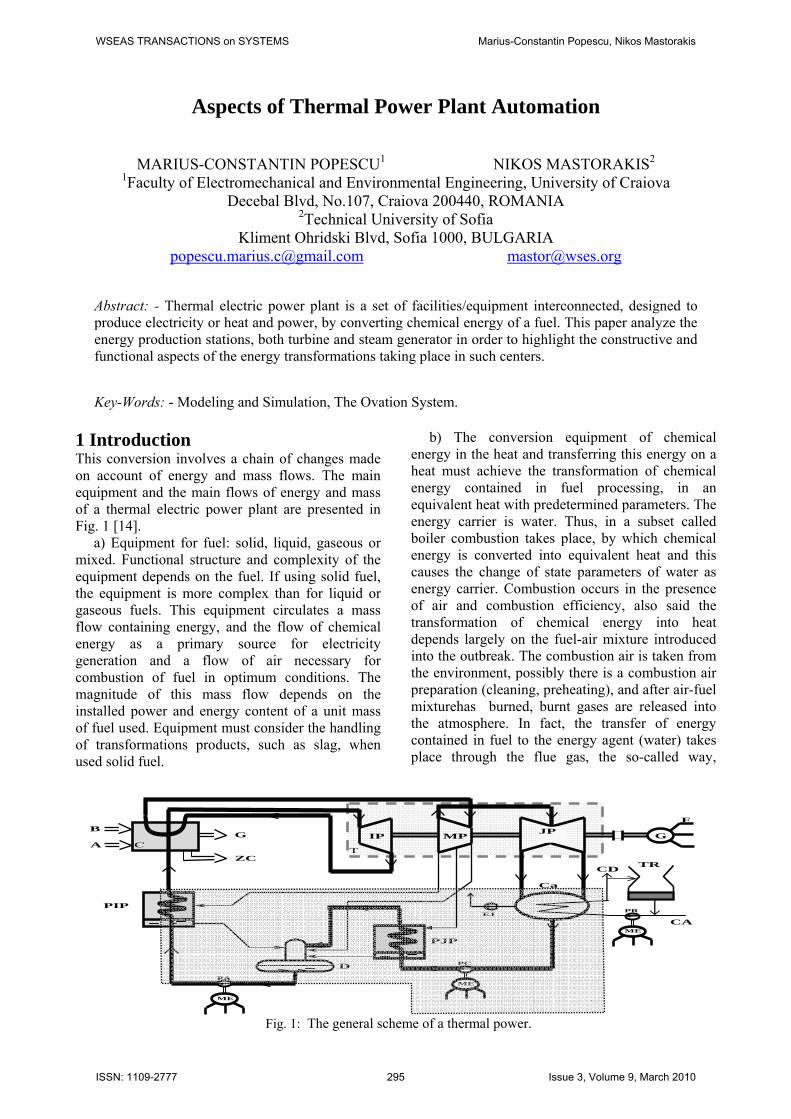
1 Introduction This conversion involves a chain of changes made on account of energy and mass flows. The main equipment and the main flows of energy and mass of a thermal electric power plant are presented in Fig. 1 [14]. a) Equipment for fuel: solid, liquid, gaseous or mixed. Functional structure and complexity of the equipment depends on the fuel. If using solid fuel, the equipment is more complex than for liquid or gaseous fuels. This equipment circulates a mass flow containing energy, and the flow of chemical energy as a primary source for electricity generation and a flow of air necessary for combustion of fuel in optimum conditions. The magnitude of this mass flow depends on the installed power and energy content of a unit mass of fuel used. Equipment must consider the handling of transformations products, such as slag, when used solid fuel.
b) The conversion equipment of chemical energy in the heat and transferring this energy on a heat must achieve the transformation of chemical energy contained in fuel processing, in an equivalent heat with predetermined parameters. The energy carrier is water. Thus, in a subset called boiler combustion takes place, by which chemical energy is converted into equivalent heat and this causes the change of state parameters of water as energy carrier. Combustion occurs in the presence of air and combustion efficiency, also said the transformation of chemical energy into heat depends largely on the fuel-air mixture introduced into the outbreak. The combustion air is taken from the environment, possibly there is a combustion air preparation (cleaning, preheating), and after air-fuel mixturehas burned, burnt gases are released into the atmosphere. In fact, the transfer of energy contained in fuel to the energy agent (water) takes place through the flue gas, the so-called way,
T
.
C A
B
ZC
G
PIP
IP MP G
E
JP
EJ
CA
TRCD
ME
PR
ME
PC
PJP
ME
PA
D
Ca
Fig. 1: The general scheme of a thermal power.
WSEAS TRANSACTIONS on SYSTEMS Marius-Constantin Popescu, Nikos Mastorakis
ISSN: 1109-2777 295 Issue 3, Volume 9, March 2010
evaporator and overheaters [2]. c) Vehicular equipment of energy agent, water vapor. It consists of hydraulic circuits through which is circulated, in closed circuit, ad the energy agent which suffers, on the route, large variations in volume, pressure and temperature. In this circuit, the power agent - water - is taken from the condenser, on low temperature and pressure and through some pumps and heat exchangers is introduced into the boiler. Into the boiler, the modification of state parameters of water take place and then it passes through the turbine (where preforming mechanical work occurs) to the capacitor, closing the circuit. d) Turbine and condenser: inside the turbine takes place the transformation of the heat energy contained in the agent, into mechanical energy of synchronous generator drive which produces electricity; the turbine beeing a rotary heat engine (prime engine). Electrical power required by the load generator can be ensured by proper power turbine, and this one, as will be shown, it can be changed depending on the steam flow and turbine adiabatic fall. The turbine condenser is designed to allow evacuation of the latent heat of vaporization of the steam in the cooling water; this heat is no longer economically useful due to temperature and especially low pressure of the steam leaving the turbine. Technological conditions of operation of the condensers require the insurance of aspiration condensate pump, while maintaining the vacuum (by condenser ejectors), avoiding excessive increase in the condensate level in the condenser. e) The condenser cooling water equipment, serves a number of important consumers beside the turbine condenser. Of these consumers we mention: air compressors, oil coolers of the turbine, electric generator and excitation circuit coolers, technological cooling. The equipment is characterized by large mass flow of 50 to 70 times bigger than the flow of energy agent. The overall yield of a thermoelectric power plant depends largely on energy efficiency of the cycle and the consumption of own technological. The yield of the heat cycle can be estimated by [8]:
cTrT
t −=η 1 (1)
where Tr and Tc are the temperatures of warm source and cold source. As seen, one way to increase the thermal efficiency is to reduce the temperature Tr. This temperature reduction occurs in the condenser (takes place a decrease of condensation temperature up to a temperature close to ambient temperature). The efficiency limit of the method is conditioned by
material and energy efforts for heat discharge into the environment [11]. The condensate cooling water is taken from the wild using pumps, and after taking the heat of condensation is returned in that environment. Cooling occurs in cooling towers, where cooling water falls drops and cool by contact with natural or forced air circulating. Loss of cooling water by evaporation (0.5÷1%) must be compensated by adding water. In addition, we mention that a steam turbine condenser fulfills two basic functions: making vacuum in the exhaust section of the water vapor in the turbine (by sudden cooling of the vapor), reintroduction of water from steam condensation in the circuit of energy agent. f) The equipment of added water introducing provides the compensation for loss of energy operator of the main heat flow; these losses have the order of 30÷40 % in the case of CET. The added water is taken from the chemical treatment plants by means of pumps and the is introduced into exchanger mixture. g) The equipment of manufacture and distribution of electricity consists of synchronous generator with static exciter or excitation, transformers attachment to bars domestic services and transformers for connection to power system bars. It is mentioned that the power of a synchronous machine can be increased either by increasing the machine size, either by increasing the electric and magnetic car stress. It means that the machine power increase raises difficulties in the heat discharge corresponding to losses. This is achieved by forced evacuation. The heat transfer developed in conductors or magnetic circuits may be achieved by indirect or direct way. There are encountered the following cooling systems: indirect air, up to 50 MW; indirect with hydrogen, over 50 MW; combined with a direct cooled with hydrogen, in the rotor, is used up to 200 MW; direct cooling with hydrogen in stator and rotor; direct cooling with liquid in the stator and direct cooling with hydrogen in the rotor, between 150÷1000 MW, direct cooling with liquid into the stator and rotor, to over 1000 MW.
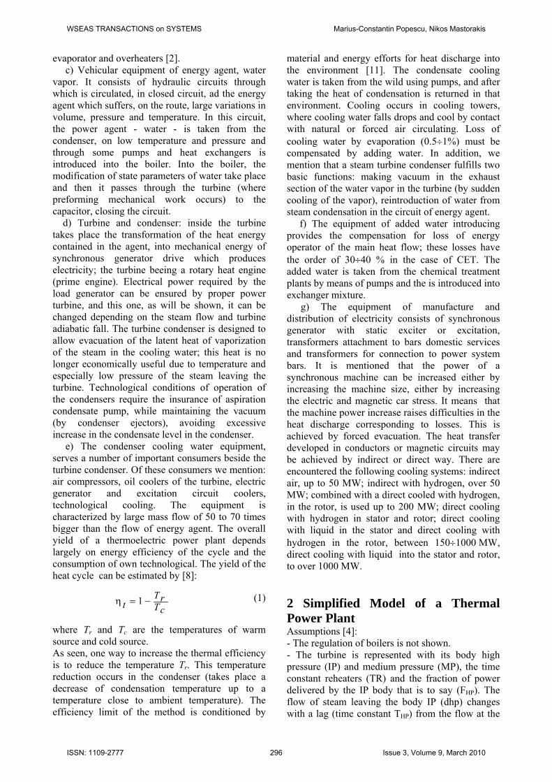
2 Simplified Model of a Thermal Power Plant Assumptions [4]: - The regulation of boilers is not shown. - The turbine is represented with its body high pressure (IP) and medium pressure (MP), the time constant reheaters (TR) and the fraction of power delivered by the IP body that is to say (FHP). The flow of steam leaving the body IP (dhp) changes with a lag (time constant THP) from the flow at the
WSEAS TRANSACTIONS on SYSTEMS Marius-Constantin Popescu, Nikos Mastorakis
ISSN: 1109-2777 296 Issue 3, Volume 9, March 2010
entrance. A fraction (FHP) of this flow is converted to dbh mechanical torque in the core is. The other fraction (1- FHP) passes into reheaters time constant TR and then in the low-pressure time constant TBP. Assuming that the MP valve is always open and we can neglect the small time constants of different body compared with the reheaters while thus reduces to a lag-lead filter (Fig. 2a). - Only the limits of openness (1) and have closed (0) valves are represented. - The power output is proportional to the speed of the turbine.
Compared to full models, the essential elements for the simplified model are: - Body high pressure (IP) turbine, represented by a pass filter - low time constant THP - Advance the filter delay time constant TR and TR *FHP, representing the turbine as explained above, the dynamics of a valve opening rate constant of TV time, which is limited between 0 and 1 pu power. The model inputs are instructed to power Preg controlling parameter, the power Pcons instruction given by the user and the frequency mechanical fmec. The output is the mechanical torque [1], [7]. Initializing the simplified model of steam turbine. At the initial instant, the mechanical torque provided is the quotient of the set of power p.u. and the mechanical frequency (=nominal
frequency f0 ) p.u.: 0f
PC CONSmec = .
The output of the integrator limited (0 to 1 p.u.) is set to the initial set of power could. This variable used to initialize the block of body high pressure (IP) filter and the delay in advance. The frequency deviation is initially zero (fmec=f0), the control power Preg is also zero. System per unit. The parameters for the turbine models defined above are expressed in per unit system whose base is the nominal active power Pnom group, defined as the product of the nominal power of the Snom alternator power factor (cospnom) the production group (Pnom - Snom*cos(pnom)). The power
to control the turbine inlet Preg is expressed in per unit. The record Pcons power can be expressed in physical size or per unit; In the latter case, the report does 1/Pnom more. The mechanical torque at the output of the model turbine is also expressed in p.u., that is, the coefficient 2n close, the ratio of mechanical power Pmec group by frequency mechanical fmec the model output of the transmission shaft. The maximum power is taken as the nominal power (Pmax=1 p.u.) and the speed of opening and closing valves or valves are expressed in p.u./s.
3 Adjustment of Combustion Air Pressure To ensure smooth functioning of the oxidation reaction of fuel elements, so to ensure maximum efficiency of converting potential energy into heat by combustion process should be introduced a certain quantity of air, A, in the outbreak. This amount depends on the flow of fuel B, of composition in elements which are oxidised and the construction of combustion system (degree of homogenization of the mixture of air - fuel). One can define air - fuel report [3]:
⎥⎦⎤
⎢⎣⎡α== kgma
BAk tAB
34.22 (2)
Theoretical amount of air ta that occurs in the expression of ABk depends on the composition of used fuel. Thus, airflow must be mentined in proportion with fuel flow (adjustment of a report), the coefficient of proportionality must be adapted to fuel composition. Since the fuel composition analysis can not be achieved continuous, but only on samples in the laboratory, you can not correct continuously the constant proportionality factor. Based on these the adjustment’s structure will contain an adjustment of fuel flow ratio (flow manager) and air flow (flow driven), the report will
a) b)
Fig. 2: Simplified model of steam turbine.
WSEAS TRANSACTIONS on SYSTEMS Marius-Constantin Popescu, Nikos Mastorakis
ISSN: 1109-2777 297 Issue 3, Volume 9, March 2010
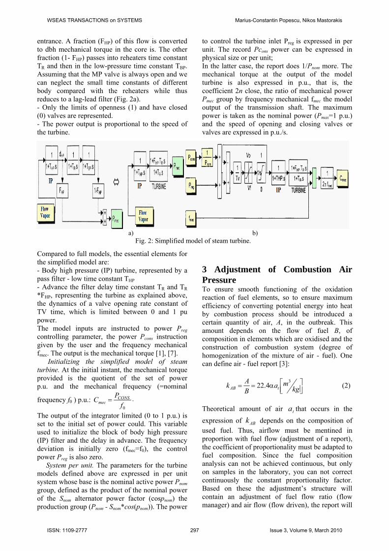
be modified depending on the concentration of oxygen in the exhaust gases and depression the outbreak. The structure of the automatic air flow is
shown in Fig. 3, where BR is a block against the possibility of further changes in the value ratio, or may be replaced with an element of multiplication, CR, is part of implementing the adjustment slider to change the combustion air flow, P is the pressure discharge of combustion air fan, fP is the depression in the outbreak, 2CO is the concentration of oxygen in the exhaust gases, Σ is adder with adjustable coefficients, ( )sHT is the transducer transfer function for each size separately. It is mentioned that in practice, due to the complex structure of the tuning system air flow and high cost of components, working with the simplified structure of the adjustment system (bounded by dotted lines in the following figure) the report of air – fuel is determinated depending on the calorific value CP of fuel and required excess air α :
( ) ⎥⎦⎤
⎢⎣⎡+α×== −
kgm P
BAk
3CAB 55.01001.1 3 (3)
If calorific fuels and constant composition can be implemented onlys simple adjustment loop and loop adjustment report (see areas defined by dotted lines). In this case the value of a prescribed size A* the regulator flow of combustion air, 1RH , is set manually or automatically as the BR report block based on variation of fuel flow B and the prescribed value (A/B)* ratio of air/fuel. If coal power groups, in which the combustion process is influenced by the quality of coal brought into focus, it is necessary to amend the r(A/B)* according to the depression in focus and content of O2, CO and CO2 of gas combustion. It is recommended that appropriate implementation of a comprehensive
structure [10] in which parameters 1k and 2k are determined on the basis of relations characterizing the combustion process or based on optimization
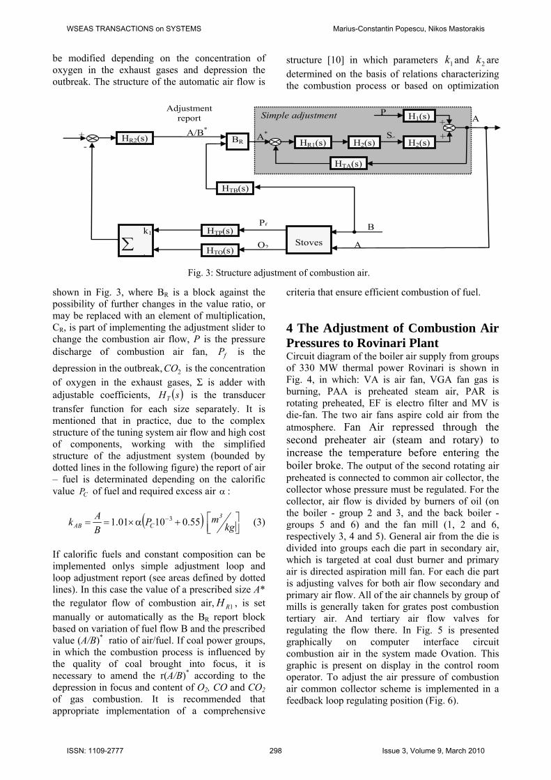
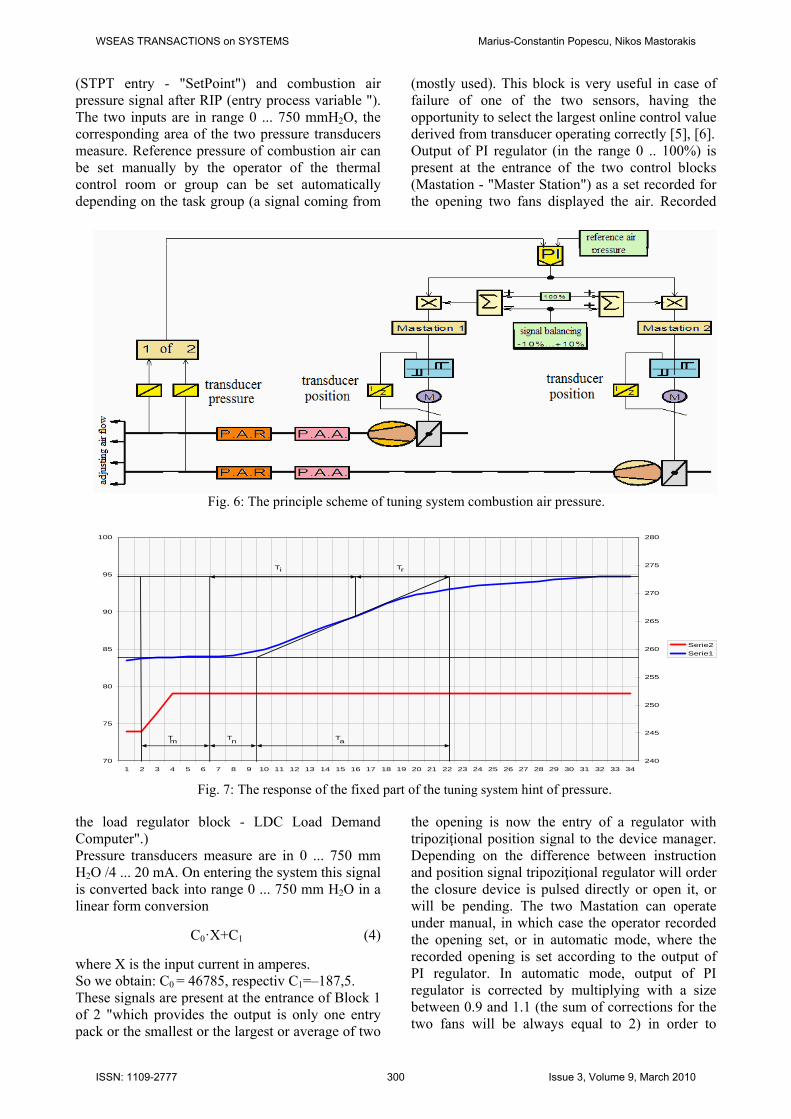
criteria that ensure efficient combustion of fuel. 4 The Adjustment of Combustion Air Pressures to Rovinari Plant Circuit diagram of the boiler air supply from groups of 330 MW thermal power Rovinari is shown in Fig. 4, in which: VA is air fan, VGA fan gas is burning, PAA is preheated steam air, PAR is rotating preheated, EF is electro filter and MV is die-fan. The two air fans aspire cold air from the atmosphere. Fan Air repressed through the second preheater air (steam and rotary) to increase the temperature before entering the boiler broke. The output of the second rotating air preheated is connected to common air collector, the collector whose pressure must be regulated. For the collector, air flow is divided by burners of oil (on the boiler - group 2 and 3, and the back boiler - groups 5 and 6) and the fan mill (1, 2 and 6, respectively 3, 4 and 5). General air from the die is divided into groups each die part in secondary air, which is targeted at coal dust burner and primary air is directed aspiration mill fan. For each die part is adjusting valves for both air flow secondary and primary air flow. All of the air channels by group of mills is generally taken for grates post combustion tertiary air. And tertiary air flow valves for regulating the flow there. In Fig. 5 is presented graphically on computer interface circuit combustion air in the system made Ovation. This graphic is present on display in the control room operator. To adjust the air pressure of combustion air common collector scheme is implemented in a feedback loop regulating position (Fig. 6).
Adjustment report Simple adjustment
HR2(s) HR1(s)
+ + BR H2(s)
AP H1(s)
+ H2(s)
Sc
HTA(s)
A*A/B*
HTB(s)
k1
∑ k
HTP(s)
HTO(s)
Stoves A
BPf
O2
-
Fig. 3: Structure adjustment of combustion air.
WSEAS TRANSACTIONS on SYSTEMS Marius-Constantin Popescu, Nikos Mastorakis
ISSN: 1109-2777 298 Issue 3, Volume 9, March 2010
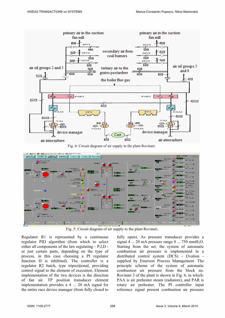
Regulator R1 is represented by a continuous regulator PID algorithm (from which to select either all components of the law regulating – P,I,D - or just certain parts, depending on the type of process, in this case choosing a PI regulator function D is inhibited). The controller is a regulator R2 batch, type tripoziţional, providing control signal to the element of execution. Element implementation of the two devices is the direction of fan air. TP position transducer element implementation provides a 4 ... 20 mA signal for the entire race device manager (from fully closed to
fully open). As pressure transducer provides a signal 4 ... 20 mA pressure range 0 ... 750 mmH2O. Starting from the set, the system of automatic combustion air pressure is implemented in a distributed control system (DCS) - Ovation - supplied by Emerson Process Management. The principle scheme of the system of automatic combustion air pressure from the block no. Rovinari 3 of the plant is shown in Fig. 6, in which: PAA is air preheater steam (radiators), and PAR is rotary air preheater. The PI controller input reference signal present combustion air pressure
Fig. 4: Circuit diagram of air supply to the plant Rovinari.
Fig. 5: Circuit diagram of air supply to the plant Rovinari.
WSEAS TRANSACTIONS on SYSTEMS Marius-Constantin Popescu, Nikos Mastorakis
ISSN: 1109-2777 299 Issue 3, Volume 9, March 2010
(STPT entry - "SetPoint") and combustion air pressure signal after RIP (entry process variable "). The two inputs are in range 0 ... 750 mmH2O, the corresponding area of the two pressure transducers measure. Reference pressure of combustion air can be set manually by the operator of the thermal control room or group can be set automatically depending on the task group (a signal coming from
the load regulator block - LDC Load Demand Computer".) Pressure transducers measure are in 0 ... 750 mm H2O /4 ... 20 mA. On entering the system this signal is converted back into range 0 ... 750 mm H2O in a linear form conversion
C0·X+C1 (4)
where X is the input current in amperes. So we obtain: C0 = 46785, respectiv C1=–187,5. These signals are present at the entrance of Block 1 of 2 "which provides the output is only one entry pack or the smallest or the largest or average of two
(mostly used). This block is very useful in case of failure of one of the two sensors, having the opportunity to select the largest online control value derived from transducer operating correctly [5], [6]. Output of PI regulator (in the range 0 .. 100%) is present at the entrance of the two control blocks (Mastation - "Master Station") as a set recorded for the opening two fans displayed the air. Recorded
the opening is now the entry of a regulator with tripoziţional position signal to the device manager. Depending on the difference between instruction and position signal tripoziţional regulator will order the closure device is pulsed directly or open it, or will be pending. The two Mastation can operate under manual, in which case the operator recorded the opening set, or in automatic mode, where the recorded opening is set according to the output of PI regulator. In automatic mode, output of PI regulator is corrected by multiplying with a size between 0.9 and 1.1 (the sum of corrections for the two fans will be always equal to 2) in order to
Fig. 6: The principle scheme of tuning system combustion air pressure.
70
75
80
85
90
95
100
1 2 3 4 5 6 7 8 9 10 11 12 13 14 15 16 17 18 19 20 21 22 23 24 25 26 27 28 29 30 31 32 33 34
240
245
250
255
260
265
270
275
280
Serie2
Serie1
Tm
T Tn a
T Ti r
Fig. 7: The response of the fixed part of the tuning system hint of pressure.
WSEAS TRANSACTIONS on SYSTEMS Marius-Constantin Popescu, Nikos Mastorakis
ISSN: 1109-2777 300 Issue 3, Volume 9, March 2010

ensure a uniform charge fans air (the same engine power absorbed by air fans) and therefore can operate with different openings of the guiding apparatus [12], [13]. 5 Determination of Transfer Function of the Fixed Part of Tuning System
To determine the transfer function of the fixed part was used experimental method, by applying a step signal at the entrance of the building and determine the response. With two Mastation the operating system "automatically" have rung the changes simulated output signal of PI regulator in both directions (to decrease and increase). These variations were 5% in either direction (variation allowed to apply for combustion air pressure).
Fig. 10: Response system to change the tabs position adjusting air flow.
Fig. 9: Reply for KP=0.2 and Ti=30 s.
Fig. 8: The answer hint of fixed parts of the combustion air pressure.
WSEAS TRANSACTIONS on SYSTEMS Marius-Constantin Popescu, Nikos Mastorakis
ISSN: 1109-2777 301 Issue 3, Volume 9, March 2010
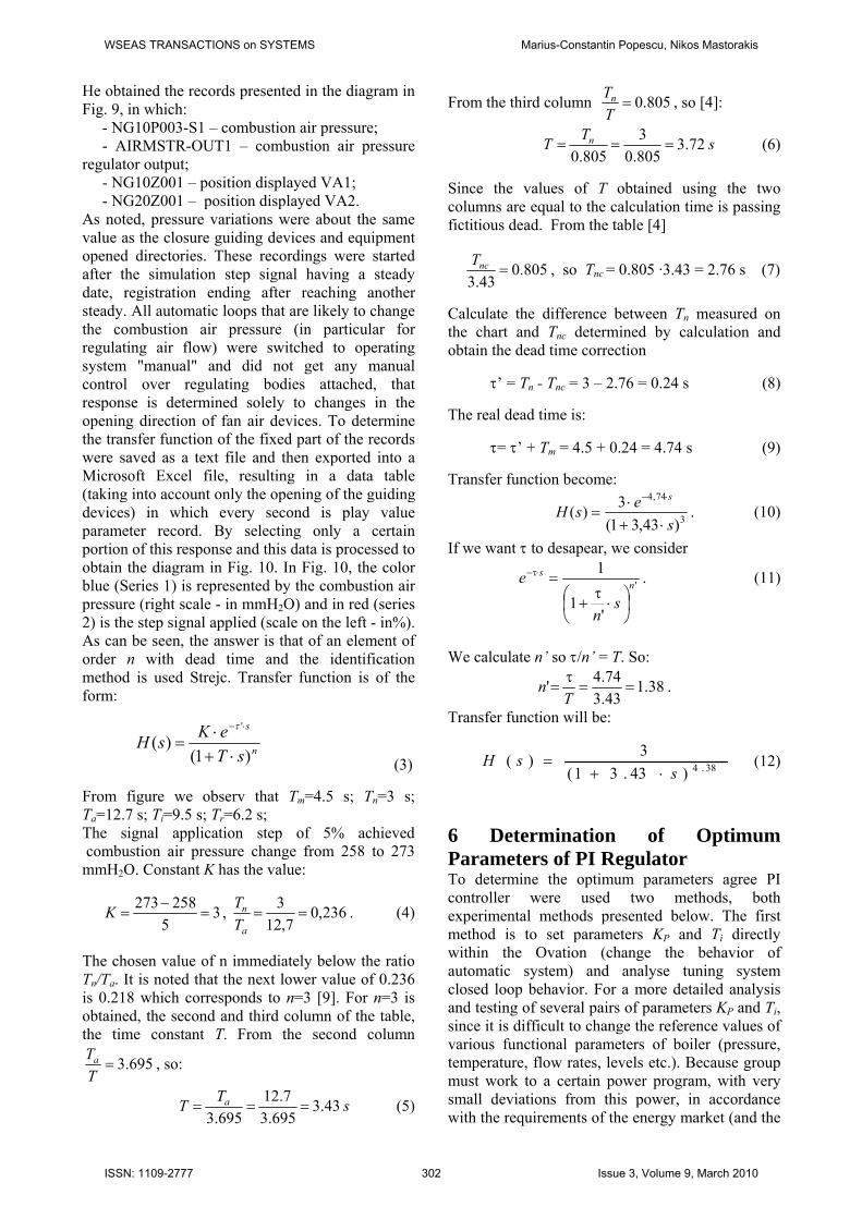
He obtained the records presented in the diagram in Fig. 9, in which: - NG10P003-S1 – combustion air pressure; - AIRMSTR-OUT1 – combustion air pressure regulator output; - NG10Z001 – position displayed VA1; - NG20Z001 – position displayed VA2. As noted, pressure variations were about the same value as the closure guiding devices and equipment opened directories. These recordings were started after the simulation step signal having a steady date, registration ending after reaching another steady. All automatic loops that are likely to change the combustion air pressure (in particular for regulating air flow) were switched to operating system "manual" and did not get any manual control over regulating bodies attached, that response is determined solely to changes in the opening direction of fan air devices. To determine the transfer function of the fixed part of the records were saved as a text file and then exported into a Microsoft Excel file, resulting in a data table (taking into account only the opening of the guiding devices) in which every second is play value parameter record. By selecting only a certain portion of this response and this data is processed to obtain the diagram in Fig. 10. In Fig. 10, the color blue (Series 1) is represented by the combustion air pressure (right scale - in mmH2O) and in red (series 2) is the step signal applied (scale on the left - in%). As can be seen, the answer is that of an element of order n with dead time and the identification method is used Strejc. Transfer function is of the form:
n
s
sTeKsH
)1()(
'
⋅+⋅
=⋅−τ
(3)
From figure we observ that Tm=4.5 s; Tn=3 s; Ta=12.7 s; Ti=9.5 s; Tr=6.2 s; The signal application step of 5% achieved combustion air pressure change from 258 to 273 mmH2O. Constant K has the value:
35
258273=
−=K , 236,0
7,123
==a
n
TT . (4)
The chosen value of n immediately below the ratio Tn/Ta. It is noted that the next lower value of 0.236 is 0.218 which corresponds to n=3 [9]. For n=3 is obtained, the second and third column of the table, the time constant T. From the second column
695.3=TTa , so:
sTT a 43.3695.3
7.12695.3
=== (5)
From the third column 805.0=TTn , so [4]:
sTT n 72.3805.03
805.0=== (6)
Since the values of T obtained using the two columns are equal to the calculation time is passing fictitious dead. From the table [4]
805.043.3
=ncT , so Tnc = 0.805 ·3.43 = 2.76 s (7)
Calculate the difference between Tn measured on the chart and Tnc determined by calculation and obtain the dead time correction τ’ = Tn - Tnc = 3 – 2.76 = 0.24 s (8)
The real dead time is: τ= τ’ + Tm = 4.5 + 0.24 = 4.74 s (9)
Transfer function become:
3
74,4
)43,31(3)(
sesH
s
⋅+⋅
=⋅−
. (10)
If we want τ to desapear, we consider
'
'1
1n
s
sn
e
⎟⎠⎞
⎜⎝⎛ ⋅
τ+
=⋅τ− . (11)
We calculate n’ so τ/n’ = T. So:
38.143.374.4' ==
τ=
Tn .
Transfer function will be:
38.4)43.31(3)(
ssH
⋅+= (12)
6 Determination of Optimum Parameters of PI Regulator To determine the optimum parameters agree PI controller were used two methods, both experimental methods presented below. The first method is to set parameters KP and Ti directly within the Ovation (change the behavior of automatic system) and analyse tuning system closed loop behavior. For a more detailed analysis and testing of several pairs of parameters KP and Ti, since it is difficult to change the reference values of various functional parameters of boiler (pressure, temperature, flow rates, levels etc.). Because group must work to a certain power program, with very small deviations from this power, in accordance with the requirements of the energy market (and the
WSEAS TRANSACTIONS on SYSTEMS Marius-Constantin Popescu, Nikos Mastorakis
ISSN: 1109-2777 302 Issue 3, Volume 9, March 2010
necessary changes would optimize load variations), we used a second method of determining the optimal parameters agree namely implementation tuning system combustion air pressure in Matlab and conduct simulations. Given the fact that the PID algorithm input sizes are made in the 0 ... 100% (combustion air pressure and reference signal for combustion air pressure is multiplied by 0.1333) and by introducing transfer functions in block diagram is obtain the system of Fig. 11. Given that the MATLAB not only can implement the transfer function form
sTKsTK⋅+⋅+
22
11 ,
realization of transfer function of the fixed part is quite difficult.
Fig. 11: Block diagram with transfer functions.
Making the transfer functions was made by four transfer functions of elements proportional to-order delay in series, as in Fig. 12, the transfer function of the fixed part becomes:
4)43.31(3)(
ssH
⋅+= .
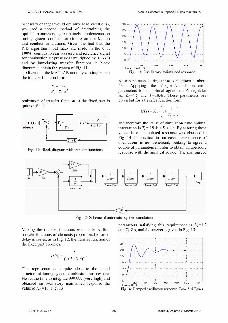
This representation is quite close to the actual structure of tuning system combustion air pressure. He set the time to integrate 999.999 (very high) and obtained an oscillatory maintained response the value of KP =10 (Fig. 13).
Fig. 13: Oscillatory maintained response.
As can be seen, during these oscillations is about 23s. Applying the Ziegler-Nichols criterion parameters for an optimal agreement PI regulator as: KP=4.5 and Ti=18.4s. These parameters are given but for a transfer function form:
⎟⎟⎠
⎞⎜⎜⎝
⎛⋅
+⋅=sT
KsHi
P11)( ,
and therefore the value of simulation time optimal integration is Ti = 18.4: 4.5 ≈ 4 s. By entering these values in our simulated response was obtained in Fig. 14. In practice, in our case, the existence of oscillations is not beneficial, seeking to agree a couple of parameters in order to obtain an aperiodic response with the smallest period. The pair agreed
parameters satisfying this requirement is KP=1.2 and Ti=8 s, and the answer is given in Fig. 15.
Fig.14: Damped oscillatory response KP=4.5 şi Ti=4 s.
Fig. 12: Scheme of automatic system simulation.
WSEAS TRANSACTIONS on SYSTEMS Marius-Constantin Popescu, Nikos Mastorakis
ISSN: 1109-2777 303 Issue 3, Volume 9, March 2010
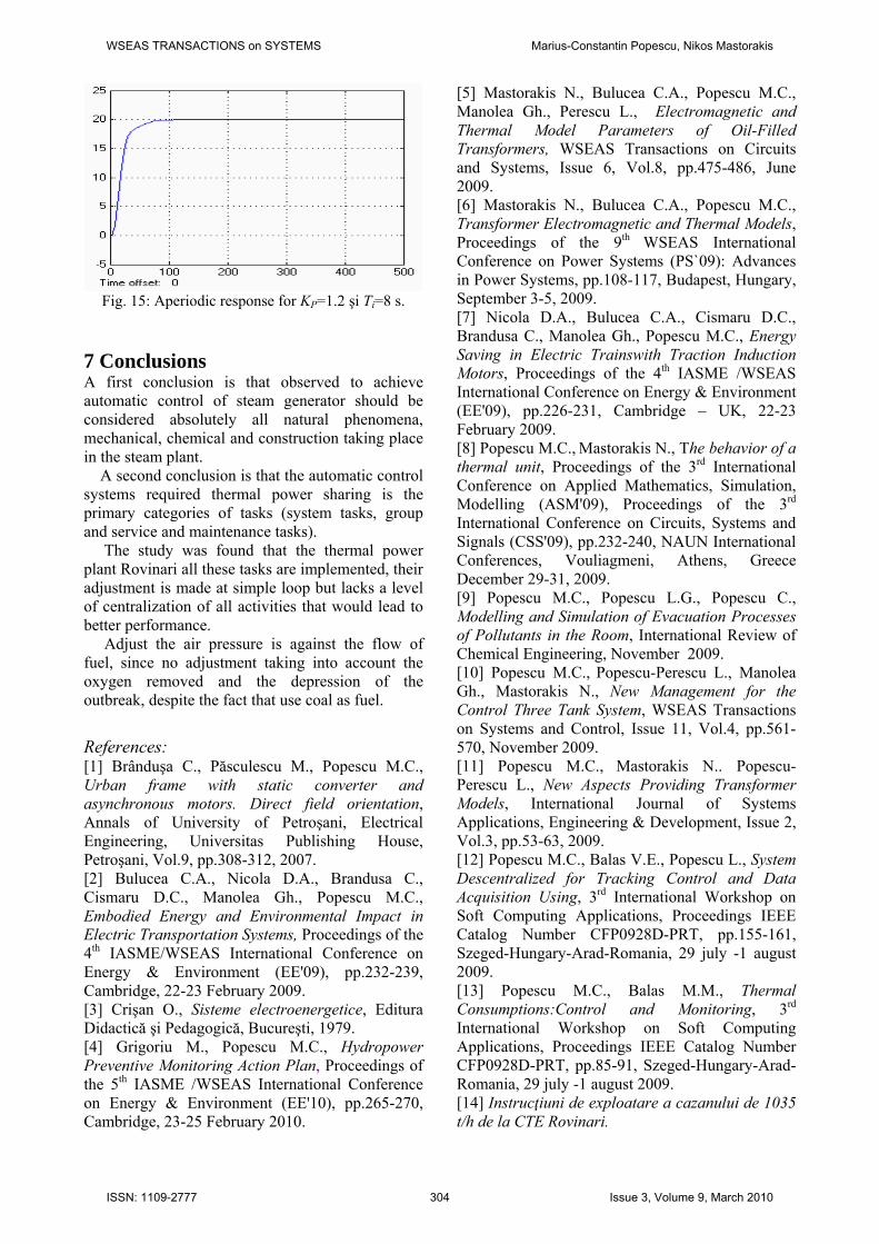
Fig. 15: Aperiodic response for KP=1.2 şi Ti=8 s.
7 Conclusions A first conclusion is that observed to achieve automatic control of steam generator should be considered absolutely all natural phenomena, mechanical, chemical and construction taking place in the steam plant. A second conclusion is that the automatic control systems required thermal power sharing is the primary categories of tasks (system tasks, group and service and maintenance tasks). The study was found that the thermal power plant Rovinari all these tasks are implemented, their adjustment is made at simple loop but lacks a level of centralization of all activities that would lead to better performance. Adjust the air pressure is against the flow of fuel, since no adjustment taking into account the oxygen removed and the depression of the outbreak, despite the fact that use coal as fuel. References: [1] Brânduşa C., Păsculescu M., Popescu M.C., Urban frame with static converter and asynchronous motors. Direct field orientation, Annals of University of Petroşani, Electrical Engineering, Universitas Publishing House, Petroşani, Vol.9, pp.308-312, 2007. [2] Bulucea C.A., Nicola D.A., Brandusa C., Cismaru D.C., Manolea Gh., Popescu M.C., Embodied Energy and Environmental Impact in Electric Transportation Systems, Proceedings of the 4th IASME/WSEAS International Conference on Energy & Environment (EE'09), pp.232-239, Cambridge, 22-23 February 2009. [3] Crişan O., Sisteme electroenergetice, Editura Didactică şi Pedagogică, Bucureşti, 1979. [4] Grigoriu M., Popescu M.C., Hydropower Preventive Monitoring Action Plan, Proceedings of the 5th IASME /WSEAS International Conference on Energy & Environment (EE'10), pp.265-270, Cambridge, 23-25 February 2010.
[5] Mastorakis N., Bulucea C.A., Popescu M.C., Manolea Gh., Perescu L., Electromagnetic and Thermal Model Parameters of Oil-Filled Transformers, WSEAS Transactions on Circuits and Systems, Issue 6, Vol.8, pp.475-486, June 2009. [6] Mastorakis N., Bulucea C.A., Popescu M.C., Transformer Electromagnetic and Thermal Models, Proceedings of the 9th WSEAS International Conference on Power Systems (PS`09): Advances in Power Systems, pp.108-117, Budapest, Hungary, September 3-5, 2009. [7] Nicola D.A., Bulucea C.A., Cismaru D.C., Brandusa C., Manolea Gh., Popescu M.C., Energy Saving in Electric Trainswith Traction Induction Motors, Proceedings of the 4th IASME /WSEAS International Conference on Energy & Environment (EE'09), pp.226-231, Cambridge – UK, 22-23 February 2009. [8] Popescu M.C., Mastorakis N., The behavior of a thermal unit, Proceedings of the 3rd International Conference on Applied Mathematics, Simulation, Modelling (ASM'09), Proceedings of the 3rd International Conference on Circuits, Systems and Signals (CSS'09), pp.232-240, NAUN International Conferences, Vouliagmeni, Athens, Greece December 29-31, 2009. [9] Popescu M.C., Popescu L.G., Popescu C., Modelling and Simulation of Evacuation Processes of Pollutants in the Room, International Review of Chemical Engineering, November 2009. [10] Popescu M.C., Popescu-Perescu L., Manolea Gh., Mastorakis N., New Management for the Control Three Tank System, WSEAS Transactions on Systems and Control, Issue 11, Vol.4, pp.561-570, November 2009. [11] Popescu M.C., Mastorakis N.. Popescu-Perescu L., New Aspects Providing Transformer Models, International Journal of Systems Applications, Engineering & Development, Issue 2, Vol.3, pp.53-63, 2009. [12] Popescu M.C., Balas V.E., Popescu L., System Descentralized for Tracking Control and Data Acquisition Using, 3rd International Workshop on Soft Computing Applications, Proceedings IEEE Catalog Number CFP0928D-PRT, pp.155-161, Szeged-Hungary-Arad-Romania, 29 july -1 august 2009. [13] Popescu M.C., Balas M.M., Thermal Consumptions:Control and Monitoring, 3rd International Workshop on Soft Computing Applications, Proceedings IEEE Catalog Number CFP0928D-PRT, pp.85-91, Szeged-Hungary-Arad-Romania, 29 july -1 august 2009. [14] Instrucţiuni de exploatare a cazanului de 1035 t/h de la CTE Rovinari.
WSEAS TRANSACTIONS on SYSTEMS Marius-Constantin Popescu, Nikos Mastorakis
ISSN: 1109-2777 304 Issue 3, Volume 9, March 2010