Embed Size (px)
Citation preview
ASSAM POWER DISTRIBUTION COMPANY
LTD.(CAZ)
BIDDING DOCUMENT FOR
CONSTRUCTION & COMMISSIONING OF DIFFERENT PACKAGES UNDER DEPOSITSCHEME
ON
“TURNKEY” BASIS
SCHEME: DEPOSIT
NIT REFERENCE: CGM (D)/APDCL (CAZ)/DEPOSIT/2012-13/01
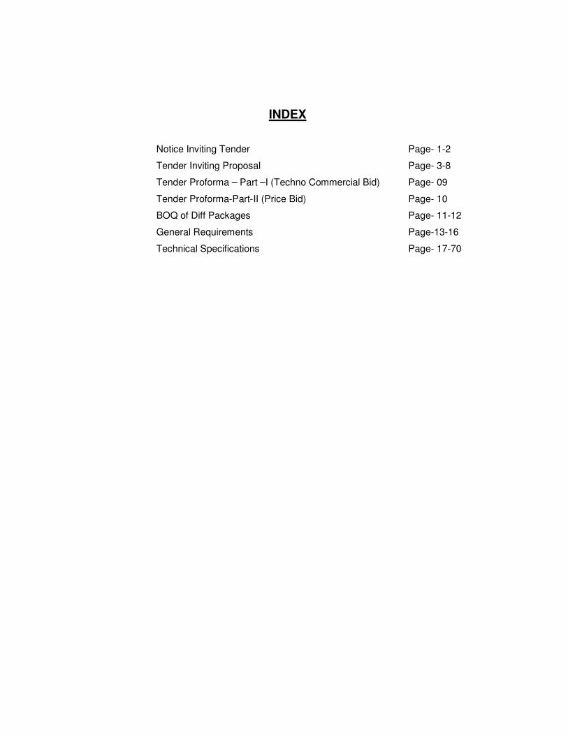
INDEX
Notice Inviting Tender Page- 1-2
Tender Inviting Proposal Page- 3-8
Tender Proforma – Part –I (Techno Commercial Bid) Page- 09
Tender Proforma-Part-II (Price Bid) Page- 10
BOQ of Diff Packages Page- 11-12
General Requirements Page-13-16
Technical Specifications Page- 17-70
APDCL , CAZ
Bid Document Deposit 12-13 Page 1
Tender Inviting Proposal APDCL(CAZ)
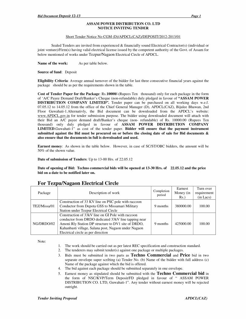
ASSAM POWER DISTRIBUTION CO. LTD
NOTICE INVITING TENDER
Short Tender Notice No CGM (D)/APDCL(CAZ)/DEPOSIT/2012-2013/01
Sealed Tenders are invited from experienced & financially sound Electrical Contractor(s) (individual or
joint venture)/Firm(s) having valid electrical license issued by the competent authority of the Govt. of Assam for
below mentioned of works under Tezpur/Nagaon Electrical Circle of APDCL.
Name of the work: As per table below.
Source of fund: Deposit
Eligibility Criteria: Average annual turnover of the bidder for last three consecutive financial years against the
package should be as per the requirements shown in the table.
Cost of Tender Paper for the Package: Rs.10000/-(Rupees Ten thousand) only for each package in the form
of ‘A/C Payee Demand Draft/Banker’s Cheque (non-refundable) duly pledged in favour of “ASSAM POWER
DISTRIBUTION COMPANY LIMITED”. Tender paper can be purchased on all working days w.e.f.
07.05.12 to 14.05.12 from the office of the Chief General Manager (D), APDCL(CAZ), Bijulee Bhawan, 2nd
Floor Guwahati-1.Alternativly, the Bid document can be downloaded from the APDCL’s website:
www.APDCL.gov.in for tender submission purpose. The bidder using downloaded document will attach with
their Bid an A/C payee demand draft/Banker’s cheque (non- refundable) of Rs. 10000.00 (Rupees Ten
thousand) only duly pledged in favour of ASSAM POWER DISTRIBUTION COMPANY
LIMITED.Guwahati-1” as cost of the tender paper. Bidder will ensure that the payment instrument
submitted against the Bid must be procured on or before the closing date of sale for Bid documents &
also ensure that the documents in full is downloaded and used.
Earnest money: As shown in the table below. However, in case of SC/ST/OBC bidders, the amount will be
50% of the shown value.
Date of submission of Tenders: Up to 13-00 Hrs. of 22.05.12
Date of opening of Bid: Techno commercial bids will be opened at 13-30 Hrs. of 22.05.12 and the price
bid on a date to be notified later on.
For Tezpu/Nagaon Electrical Circle
Package Description of work Completion
period
Earnest
Money (in
Rs.)
Turn over
requirement
(in Lacs)
TEZ/Missa/01
Construction of 33 KV line on PSC pole with raccoon
Conductor from Depota GSS to Missamari Military
Station under Tezpur Electrical Circle
9 months 380000.00 100.00
NG/DRDO/02
Construction of 33kV line on GI Pole with raccoon
conductor from DRDO dedicated 33kV line tapping near
Amoni Rly Station DP structure to DV1 site of DRDO,
Kahanbasti village, Salana post, Nagaon under Nagaon
Electrical circle as per direction
9 months 425000.00 100.00
Note:
1. The work should be carried out as per latest REC specification and construction standard.
2. The tenderers may submit tender(s) against one package or multiple packages.
3. Bids must be submitted in two parts as Techno Commercial and Price bid in two
separate envelope super scribing (a) Tender No. (b) Name of the bidder with full address (c)
Name of the package against which the bid is offered.
4. The bid against each package should be submitted separately in one envelope.
5. Earnest money as stipulated should be submitted with the Techno Commercial bid in
the form of NSC/KVP/Term Deposit/FD pledged in favour of “ ASSAM POWER
DISTRIBUTION CO. LTD, Guwahati-1”. Any tender without earnest money will be rejected
outright.
Bid Document Deposit 12-13 Page 2
Tender Inviting Proposal APDCL(CAZ)
6. Part-I of the Bid shall consists of information as required and all Technical Bidding
Schedules (GTP), all Price Bidding Schedules with all quantities filled up but without
any Price, etc and Part-II shall consists of Price Bidding Schedules with all quantities
and prices filled up. Details are available in General Instruction to Bidder in Section-2,
Volume-1 of the Bid Document
7. Quoted rate should be inclusive of all taxes and duties and firm. Taxes should be shown
separately
8. Quote rate must valid for minimum 180 days.
9. The tender should be addressed and submitted in the office of the Chief General Manager
(D), APDCL (CAZ), Bijulee Bhawan, 2nd
floor, Paltanbazar, Guwahati-1 and will be opened
on the scheduled date & time in presence of the intending tenderers.
10. Only those bidders whose Part-I Bid ie. Techno Commercial bid (Qualification) is found
acceptable shall be considered for opening of Price Bid. The date and time of opening of Part-
II Bid (Price) shall be communicated to those bidders whose bids are qualified for opening.
11. The Company reserves the right to accept or reject any tender in part or in full or spilt the
work of any package without showing any reason thereof.
12. The bidding documents are not transferable and cost of bidding document is not refundable
under any circumstances. 13. The bidder who has downloaded the documents from our website must intimate the same to
our e-mail address without fail.
Chief General Manager (D),
APDCL, Bijulee Bhawan,
Paltanbazar, Guwahati-781001
Bid Document Deposit 12-13 Page 3
Tender Inviting Proposal APDCL(CAZ)
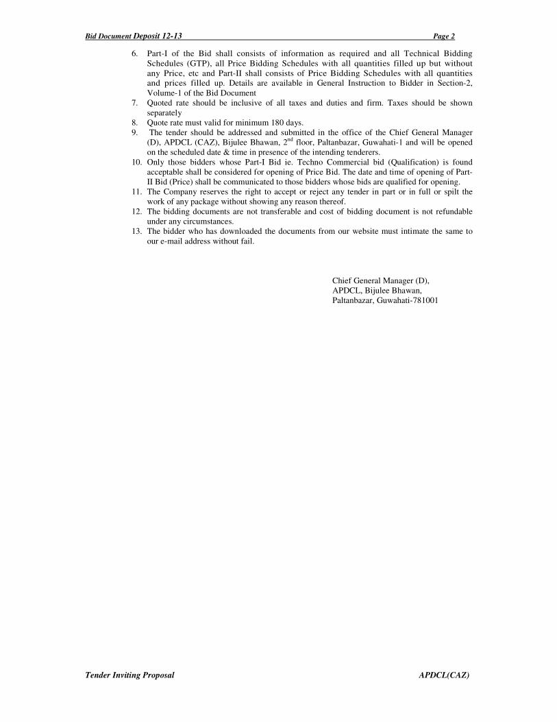
ASSAM POWER DISTRIBUTION COMPANY LTD OFFICE OF THE CHIEF GENERAL MANAGER (D), APDCL, (CAZ) GUWAHATI-1
TENDER INVITING PROPOSALS WITH TERMS & CONDITIONS
FOR CONSTRUCTION OF 33 KV line, ON TURNKEY BASIS 1. Intent of the Tender Enquiry
The intent of the Tender Enquiry is to invite proposals from the prospective and relevantly experienced and financially sound contractor(s) (individual or joint venture)/firms to carry out the
work of construction of 33 KV lines on turnkey basis as per the scope of work described in the
following.
2. Scope of Work
The various activities under the scope of work shall among other related aspects cover the following. i. Procurement and supply of all materials required for the work.
ii. Site unloading, storage and handling of all materials supplied including watch and ward for
safe custody.
iii. Site fabrication work as per requirement.
iv. Submission of implementation schedule from the date of award of contract for: -
• Route survey for laying new line.
• Erection, testing and commissioning of all materials/equipment supplied/system installed.
v. Project management and site organization.
vi. Obtaining clearance from statutory Agencies, Government Departments, Village Panchayats
etc.
vii. Submission of specification/Test Certificate/Drawings etc. of all materials supplied.
viii. A list of various items normally involved in proposed type of work is provided in this
document. This, however, is not to be considered as limiting but only typical. Vendors’ scope
will include all other items and materials as may be required to effectively complete the work.
ix. Required Jungle cutting.
Above all, the scope of work of the vendor/contractor will include all items and facilities as may be
necessary to complete the electrification work on turnkey basis and as binding requirement.
3. Basic specification of the various equipment/ works to be supplied carried out.
i. All equipment supplied shall conform to the requirement of relevant ISS (BIS) as approved
by Company and that of REC specification and construction standards. ii. For ready reference, the basic specification of major items, namely- Transformer, conductor,
GI angle for cross bracing, Polymer Disc insulator (70 KN), disc attachment for raccoon
conductor, 33 KV polymer pin insulator, GI channel, 100X50X6X2200 mm, HT stay set, guy
insulator, stay wire, CI earth pipe, GI wire 4/6 SWG, nuts & bolts, washer, G.I tubular pole,
PSC pole, , danger plate, pole clamps, boulder for PSC pole grouting, PCC for G.I tubular
pole grouting, are provided in the Technical Specification Section. Based on this, the vendor shall draw total specification for procurement after approval of Company.
iii. All materials supplied shall be erected, protected as per approved standard practice for
proposed type of electrical work so as to supply electricity to the consumers most effectively
and in an intrinsically safe manner.
iv. All equipment supplied and installed shall provide easy and effective:
• Maintainability
• Reliability
• Availability
• Long life
All equipment supplied and installed shall be provided stable and adequate weather protection, system earthing etc.
Bid Document Deposit 12-13 Page 4
Tender Inviting Proposal APDCL(CAZ)
v. All items, which may require frequent opening up/ dismantling for maintenance, shall be adequately sealed against any tampering/ theft etc.
vi. All supporting structures shall be of steel as per IS 2602 appropriate grad.
vii. Generally supply and erection of materials and system shall meet the requirement laid down
by REC for rural electrification works.
4. Submission of bid
The bid shall be submitted in a sealed envelope as follows:
i. Techno-commercial bid
Under this will be included and defined vendors scope of work, responsibilities, guarantees,
specification of equipment, commercial terms and conditions, vendor’s company credentials,
experience of similar assignments, registration details, etc. as per requirement. Tender proforma
for techno-commercial Bid is enclosed as Annexure-I.
ii. Price Bid
Under this will include rates of supply and erection of different items for electrification. The
tender proforma for price Bid is enclosed as Annexure-II.
5. Estimation of material requirement:
The total quantity of materials required in each package is indicated in the Package wise BOQ in
Section 1
6. Award of work: i) The evaluation of bids will be carried out, first of techno-commercial bid and thereafter opening
the price bid of only those who qualify and meet the technical requirement.
ii) Company reserves the right not to order/ award the job to the price-wise lowest party if the
party during evaluation is found technically non responsive.
iii) Work should be started within fifteen (15) days from the date of issue of the work order, failing
which order will be cancelled without further correspondence.
iv) The line/Sub-station after completion should be under custody of the contractor till the date of
commissioning and charging. The properties will be taken over by APDCL after satisfactory
commissioning and charging.
7. Period of completion: Nine (9) months from the date of award of work contract.
Bid Document Deposit 10-11 Page 5
CAEDCL
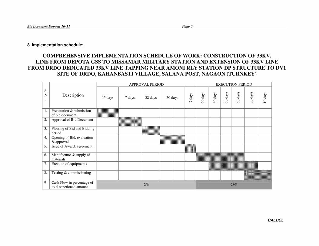
8. Implementation schedule:
COMPREHENSIVE IMPLEMENTATION SCHEDULE OF WORK: CONSTRUCTION OF 33KV,
LINE FROM DEPOTA GSS TO MISSAMAR MILITARY STATION AND EXTENSION OF 33KV LINE
FROM DRDO DEDICATED 33KV LINE TAPPING NEAR AMONI RLY STATION DP STRUCTURE TO DV1 SITE OF DRDO, KAHANBASTI VILLAGE, SALANA POST, NAGAON (TURNKEY)
APPROVAL PERIOD EXECUTION PERIOD
S.
N
. Description
15 days 7 days. 32 days 30 days
7 d
ays
60 d
ays
60 d
ays
60 d
ays
50 d
ays
30 d
ays
10 d
ays
1. Preparation & submission
of bid document
2. Approval of Bid Document
3. Floating of Bid and Bidding
period
4. Opening of Bid, evaluation
& approval
5. Issue of Award, agreement
6. Manufacture & supply of
materials
7. Erection of equipments
8. Testing & commissioning
9 Cash Flow in percentage of
total sanctioned amount 2% 98%
Bid Document Deposit 10-11 Page No 6
Notice Inviting Tender APDCL
9. Termination of work order:
Company reserves the right to terminate the work order at any stage in accordance with the
Company’s General Condition of Supply and Erection.
10.1 Terms of Payment:
During currency of the Contract, maximum 4(four) nos. of progressive Bills will be allowed.
Each progressive Bills should contain items of works which are completed in all respect of supply,
erection for the identified locations . 80% of each progressive Bill shall be paid retaining 20% by the
company (APDCL).
Final Bills will be paid comprising balance works beyond the works already claimed in the
progressive Bills alongwith 20% of the amount retained against the progressive Bills subject to
testing and commissioning & fulfillment of clause-14(d).
10.2 Earnest Money Deposit (EMD):
The Tender must be accompanied with earnest money as mentioned in the NIT against each
package to be deposited in the form of NSC/KVP/Term Deposit/FD pledged in favour
of “ASSAM POWER DISTRIBUTION CO. LTD. Guwahti-1”. The earnest money to the
unsuccessful bidders will be released on finalization of the tenders. The EMD to the
successful bidder will be released on submission of Security Deposit at the time of
execution of the agreement.
10.3 Security deposit and agreement:
The successful bidders shall have to deposit security money in the form of Bank Guarantee
issued by any Nationalized Bank/Scheduled Bank in Company’s standard proforma on non-
judicial stamp of appropriate value for an amount equal to 2.5% of the contract value at the
time of execution of agreement. The security deposit is liable to be forfeited in case of non-
execution of contract/ work order. The security deposit will be released on successful
commissioning and testing of the materials ordered and after depositing performance B/G as
per clause 14(d).
11. Basic qualifying requirement:
The prospective bidder must fulfill the following pre-bid qualifying requirement
a. The bidder must have valid electrical Contractor’s and Supervisor’s License (HT) issued
by the Licensing Authority of Govt. Of Assam. .
b. The bidder must have adequate experience of doing similar job on turnkey basis at least
15 KM in total.
c. Average annual turnover of the bidder for last three consecutive financial years should
be at least as per the requirement shown in the table against particular package or
packages and the annual turnover should be certified by a registered Chartered
Accountant with balance sheet.
d. The tenderer shall furnish latest Income Tax clearance certificate and sales tax
registration and valid Labour License and WCT registration Certificate.
12. Other requirements:
The Tenderer
i) Should be acquainted himself or his associate with relevant conditions of the local
geography and socio economic setup of the different location of the State and being
capable accordingly to mobilize, organize and expedite the activities.
ii) Should have adequate working personnel comprising of Electrical/ Mechanical
engineers, electrical supervisor, skilled and unskilled labour to be deputed to the
proposed assignment.
Bid Document Deposit 10-11 Page No 7
Notice Inviting Tender APDCL
iii) Should be conversant with the code/ standards applicable to proposed type of work.
ISS, REC guidelines.
13. Project Management and site Organizations:
In Consideration of the tight schedule of the project, the successful bidder(s) /Contractor(s)
shall exercise systematic closely controlled project management system with the aid of
commonly used soft tools. Following are the major activities/deliverables to be organized
/generated for submission to the Board.
(I) Liaison/Construction offices will be established in each Circle of APDCL.
(II) Work Progress Report:
• Progress monitoring by the contractor as per implementation schedule and approved
milestones.
• Fortnightly progress report will be submitted to the concern Deputy General
Manager, Senior Manager & Sub-Divisional Engineers.
The progress report will highlight the points like, work completion vis-à-vis
planned, plan for next working period, delay analysis vis-à-vis committed schedule
with reasons and remedies etc.
(III) Site Organization.
The vendor at each working site shall establish the following.
• Store house
• Site fabrication facilities
• Construction supervision office
All offices shall be adequately furnished and staffed so as to take all site decisions independently without frequent references to head Work’s/offices.
14. Guarantees and Penalties
a) Liquidated Damages (LD)
The proposed work is on top priority of Government of India and therefore has to be
completed within stipulated/agreed schedule. Any delay beyond that will attract penalty as
per Company’s general condition of supply and erection.
b) Equipment and system installed shall be guaranteed individually for integrated operations
for a period of 18 (Eighteen) months from date of commissioning of a system. In case of
detection of any defect in individual equipment or system as a whole, the same shall be
replaced by the vendor free of cost within 15 days of intimation by the Company’s
representative.
c) Warranty from the manufacturer shall be produced along with manufacturer’s test certificate
for the following items
• All Types of Insulators with Hardware fittings.
• Conductor.
• Stay set
• All other equipment usually covered under Manufacturer’s warranty
d) A performance Bank Guarantee from a Nationalized Bank/Scheduled Bank in Board’s standard proforma on Non judicial stamp paper of appropriate value with a validity of 18
(eighteen) months @ 10% of total value of work executed shall have to be furnished by the
Contractor before final payment.
Bid Document Deposit 10-11 Page No 8
Notice Inviting Tender APDCL
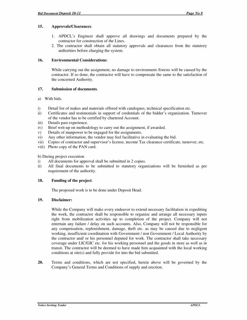
15. Approvals/Clearances:
1. APDCL’s Engineer shall approve all drawings and documents prepared by the
contractor for construction of the Lines.
2. The contractor shall obtain all statutory approvals and clearances from the statutory
authorities before charging the system.
16. Environmental Considerations:
While carrying out the assignment, no damage to environment /forests will be caused by the
contractor. If so done, the contractor will have to compensate the same to the satisfaction of
the concerned Authority.
17. Submission of documents.
a) With bids.
i) Detail list of makes and materials offered with catalogues, technical specification etc.
ii) Certificates and testimonials in support of credentials of the bidder’s organization. Turnover
of the vendor has to be certified by chartered Account. iii) Details past experience.
iv) Brief writ-up on methodology to carry out the assignment, if awarded.
v) Details of manpower to be engaged for the assignments.
vi) Any other information, the vendor may feel facilitative in evaluating the bid.
vii) Copies of contractor and supervisor’s license, income Tax clearance certificate, turnover, etc.
viii) Photo copy of the PAN card.
b) During project execution
i) All documents for approval shall be submitted in 2 copies.
ii) All final documents to be submitted to statutory organizations will be furnished as per
requirement of the authority.
18. Funding of the project.
The proposed work is to be done under Deposit Head.
19. Disclaimer:
While the Company will make every endeavor to extend necessary facilitation in expediting
the work, the contractor shall be responsible to organize and arrange all necessary inputs
right from mobilization activities up to completion of the project. Company will not
entertain any failure / delay on such accounts. Also, Company will not be responsible for
any compensation, replenishment, damage, theft etc. as may be caused due to negligent
working, insufficient coordination with Government / non Government / Local Authority by
the contractor and/ or his personnel deputed for work. The contractor shall take necessary
coverage under LIC/GIC etc. for his working personnel and the goods in store as well as in
transit. The contractor will be deemed to have made him acquainted with the local working conditions at site(s) and fully provide for into the bid submitted.
20. Terms and conditions, which are not specified, herein above will be governed by the
Company’s General Terms and Conditions of supply and erection.
Bid Document Deposit 10-11 Page No 9
Notice Inviting Tender APDCL
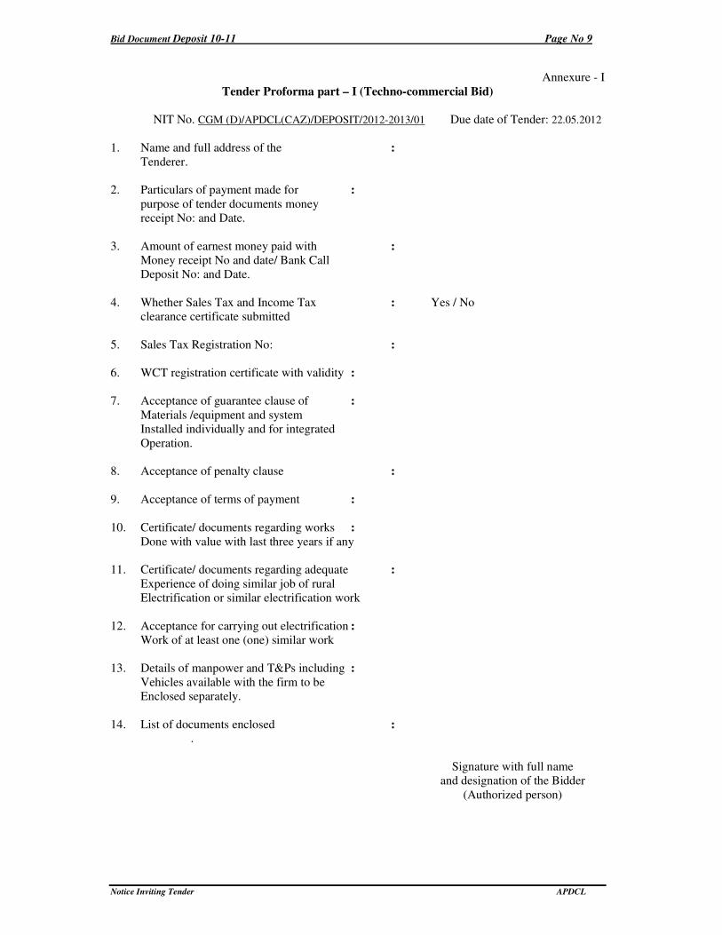
Annexure - I
Tender Proforma part – I (Techno-commercial Bid)
NIT No. CGM (D)/APDCL(CAZ)/DEPOSIT/2012-2013/01 Due date of Tender: 22.05.2012
1. Name and full address of the :
Tenderer.
2. Particulars of payment made for :
purpose of tender documents money
receipt No: and Date.
3. Amount of earnest money paid with :
Money receipt No and date/ Bank Call
Deposit No: and Date.
4. Whether Sales Tax and Income Tax : Yes / No
clearance certificate submitted
5. Sales Tax Registration No: :
6. WCT registration certificate with validity :
7. Acceptance of guarantee clause of :
Materials /equipment and system
Installed individually and for integrated
Operation.
8. Acceptance of penalty clause :
9. Acceptance of terms of payment :
10. Certificate/ documents regarding works :
Done with value with last three years if any
11. Certificate/ documents regarding adequate :
Experience of doing similar job of rural
Electrification or similar electrification work
12. Acceptance for carrying out electrification :
Work of at least one (one) similar work
13. Details of manpower and T&Ps including :
Vehicles available with the firm to be
Enclosed separately.
14. List of documents enclosed : .
Signature with full name
and designation of the Bidder
(Authorized person)
Bid Document Deposit 10-11 Page No 10
Notice Inviting Tender APDCL
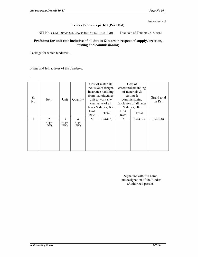
Annexure - II
Tender Proforma part-II (Price Bid)
NIT No. CGM (D)/APDCL(CAZ)/DEPOSIT/2012-2013/01 Due date of Tender: 22.05.2012
Proforma for unit rate inclusive of all duties & taxes in respect of supply, erection,
testing and commissioning
Package for which tendered: -
Name and full address of the Tenderer:
.
Cost of materials
inclusive of freight,
insurance handling
from manufacturer
unit to work site
(inclusive of all
taxes & duties) Rs.
Cost of
erection/dismantling
of materials &
testing &
commissioning
(inclusive of all taxes
& duties) Rs.
Sl.
No Item Unit Quantity
Unit
Rate Total
Unit
Rate Total
Grand total
in Rs.
1 2 3 4 5 6=(4x5) 7 8=(4x7) 9=(6+8)
As per
BOQ
As per
BOQ As per
BOQ
Signature with full name
and designation of the Bidder
(Authorized person)
Bid Document Deposit 10-11 Page No 11
Notice Inviting Tender APDCL
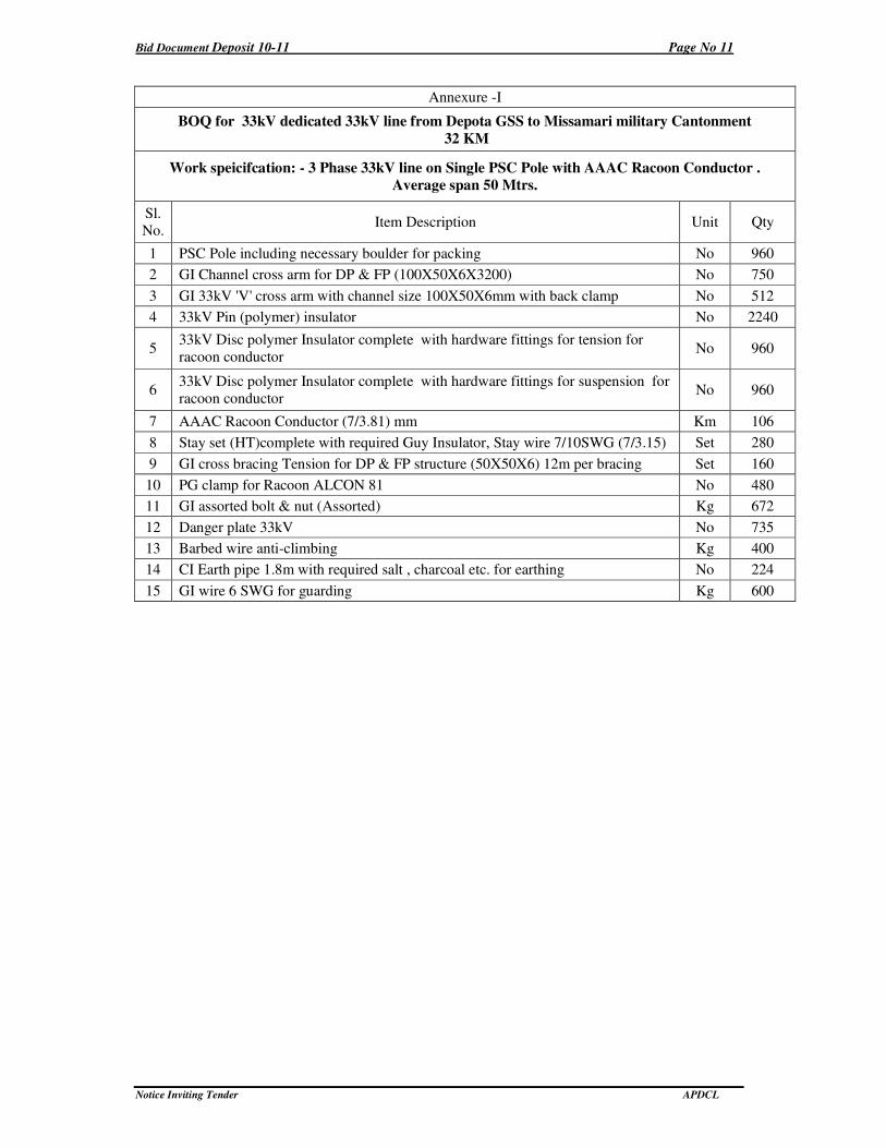
Annexure -I
BOQ for 33kV dedicated 33kV line from Depota GSS to Missamari military Cantonment
32 KM
Work speicifcation: - 3 Phase 33kV line on Single PSC Pole with AAAC Racoon Conductor .
Average span 50 Mtrs.
Sl.
No. Item Description Unit Qty
1 PSC Pole including necessary boulder for packing No 960
2 GI Channel cross arm for DP & FP (100X50X6X3200) No 750
3 GI 33kV 'V' cross arm with channel size 100X50X6mm with back clamp No 512
4 33kV Pin (polymer) insulator No 2240
5 33kV Disc polymer Insulator complete with hardware fittings for tension for
racoon conductor No 960
6 33kV Disc polymer Insulator complete with hardware fittings for suspension for
racoon conductor No 960
7 AAAC Racoon Conductor (7/3.81) mm Km 106
8 Stay set (HT)complete with required Guy Insulator, Stay wire 7/10SWG (7/3.15) Set 280
9 GI cross bracing Tension for DP & FP structure (50X50X6) 12m per bracing Set 160
10 PG clamp for Racoon ALCON 81 No 480
11 GI assorted bolt & nut (Assorted) Kg 672
12 Danger plate 33kV No 735
13 Barbed wire anti-climbing Kg 400
14 CI Earth pipe 1.8m with required salt , charcoal etc. for earthing No 224
15 GI wire 6 SWG for guarding Kg 600
Bid Document Deposit 10-11 Page No 12
Notice Inviting Tender APDCL
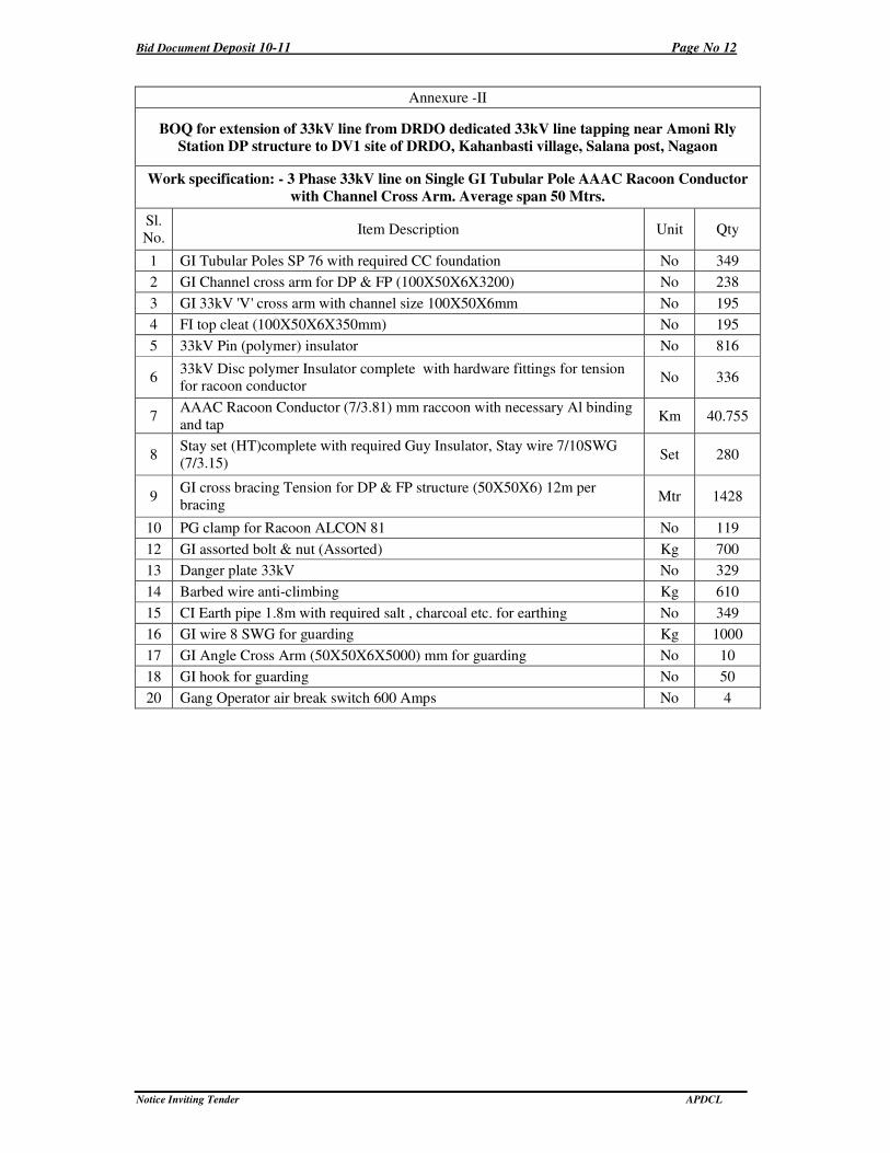
Annexure -II
BOQ for extension of 33kV line from DRDO dedicated 33kV line tapping near Amoni Rly
Station DP structure to DV1 site of DRDO, Kahanbasti village, Salana post, Nagaon
Work specification: - 3 Phase 33kV line on Single GI Tubular Pole AAAC Racoon Conductor
with Channel Cross Arm. Average span 50 Mtrs.
Sl.
No. Item Description Unit Qty
1 GI Tubular Poles SP 76 with required CC foundation No 349
2 GI Channel cross arm for DP & FP (100X50X6X3200) No 238
3 GI 33kV 'V' cross arm with channel size 100X50X6mm No 195
4 FI top cleat (100X50X6X350mm) No 195
5 33kV Pin (polymer) insulator No 816
6 33kV Disc polymer Insulator complete with hardware fittings for tension for racoon conductor
No 336
7 AAAC Racoon Conductor (7/3.81) mm raccoon with necessary Al binding
and tap Km 40.755
8 Stay set (HT)complete with required Guy Insulator, Stay wire 7/10SWG
(7/3.15) Set 280
9 GI cross bracing Tension for DP & FP structure (50X50X6) 12m per
bracing Mtr 1428
10 PG clamp for Racoon ALCON 81 No 119
12 GI assorted bolt & nut (Assorted) Kg 700
13 Danger plate 33kV No 329
14 Barbed wire anti-climbing Kg 610
15 CI Earth pipe 1.8m with required salt , charcoal etc. for earthing No 349
16 GI wire 8 SWG for guarding Kg 1000
17 GI Angle Cross Arm (50X50X6X5000) mm for guarding No 10
18 GI hook for guarding No 50
20 Gang Operator air break switch 600 Amps No 4
Bid Document Deposit 10-11 Page No 13
Notice Inviting Tender APDCL
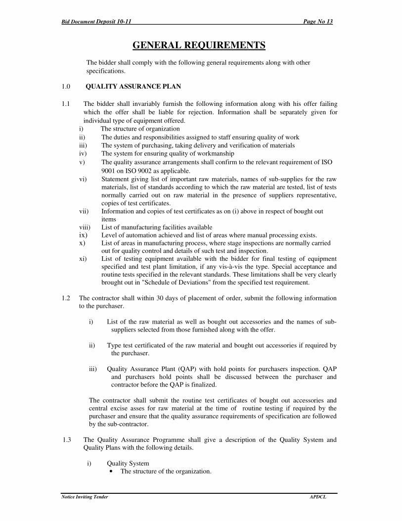
GENERAL REQUIREMENTS
The bidder shall comply with the following general requirements along with other
specifications.
1.0 QUALITY ASSURANCE PLAN
1.1 The bidder shall invariably furnish the following information along with his offer failing
which the offer shall be liable for rejection. Information shall be separately given for
individual type of equipment offered.
i) The structure of organization
ii) The duties and responsibilities assigned to staff ensuring quality of work
iii) The system of purchasing, taking delivery and verification of materials
iv) The system for ensuring quality of workmanship
v) The quality assurance arrangements shall confirm to the relevant requirement of ISO
9001 on ISO 9002 as applicable.
vi) Statement giving list of important raw materials, names of sub-supplies for the raw
materials, list of standards according to which the raw material are tested, list of tests
normally carried out on raw material in the presence of suppliers representative,
copies of test certificates.
vii) Information and copies of test certificates as on (i) above in respect of bought out
items
viii) List of manufacturing facilities available
ix) Level of automation achieved and list of areas where manual processing exists. x) List of areas in manufacturing process, where stage inspections are normally carried
out for quality control and details of such test and inspection. xi) List of testing equipment available with the bidder for final testing of equipment
specified and test plant limitation, if any vis-à-vis the type. Special acceptance and
routine tests specified in the relevant standards. These limitations shall be very clearly
brought out in "Schedule of Deviations" from the specified test requirement.
1.2 The contractor shall within 30 days of placement of order, submit the following information
to the purchaser.
i) List of the raw material as well as bought out accessories and the names of sub-
suppliers selected from those furnished along with the offer.
ii) Type test certificated of the raw material and bought out accessories if required by
the purchaser.
iii) Quality Assurance Plant (QAP) with hold points for purchasers inspection. QAP
and purchasers hold points shall be discussed between the purchaser and
contractor before the QAP is finalized.
The contractor shall submit the routine test certificates of bought out accessories and
central excise asses for raw material at the time of routine testing if required by the
purchaser and ensure that the quality assurance requirements of specification are followed
by the sub-contractor.
1.3 The Quality Assurance Programme shall give a description of the Quality System and
Quality Plans with the following details.
i) Quality System
• The structure of the organization.
Bid Document Deposit 10-11 Page No 14
Notice Inviting Tender APDCL
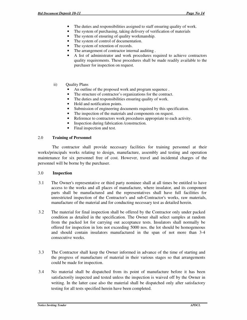
• The duties and responsibilities assigned to staff ensuring quality of work.
• The system of purchasing, taking delivery of verification of materials
• The system of ensuring of quality workmanship.
• The system of control of documentation.
• The system of retention of records.
• The arrangement of contractor internal auditing .
• A list of administrator and work procedures required to achieve contractors
quality requirements. These procedures shall be made readily available to the
purchaser for inspection on request.
ii) Quality Plans
• An outline of the proposed work and program sequence .
• The structure of contractor’s organizations for the contract.
• The duties and responsibilities ensuring quality of work.
• Hold and notification points.
• Submission of engineering documents required by this specification.
• The inspection of the materials and components on request.
• Reference to contractors work procedures appropriate to each activity.
• Inspection during fabrication /construction.
• Final inspection and test.
2.0 Training of Personnel
The contractor shall provide necessary facilities for training personnel at their
works/principals works relating to design, manufacture, assembly and testing and operation
maintenance for six personnel free of cost. However, travel and incidental charges of the
personnel will be borne by the purchaser.
3.0 Inspection
3.1 The Owner's representative or third party nominee shall at all times be entitled to have access to the works and all places of manufacture, where insulator, and its component parts shall be manufactured and the representatives shall have full facilities for unrestricted inspection of the Contractor's and sub-Contractor's works, raw materials, manufacture of the material and for conducting necessary test as detailed herein.
3.2 The material for final inspection shall be offered by the Contractor only under packed
condition as detailed in the specification. The Owner shall select samples at random
from the packed lot for carrying out acceptance tests. Insulators shall normally be
offered for inspection in lots not exceeding 5000 nos. the lot should be homogeneous
and should contain insulators manufactured in the span of not more than 3-4
consecutive weeks.
3.3 The Contractor shall keep the Owner informed in advance of the time of starting and
the progress of manufacture of material in their various stages so that arrangements
could be made for inspection.
3.4 No material shall be dispatched from its point of manufacture before it has been
satisfactorily inspected and tested unless the inspection is waived off by the Owner in
writing. In the latter case also the material shall be dispatched only after satisfactory
testing for all tests specified herein have been completed.
Bid Document Deposit 10-11 Page No 15
Notice Inviting Tender APDCL
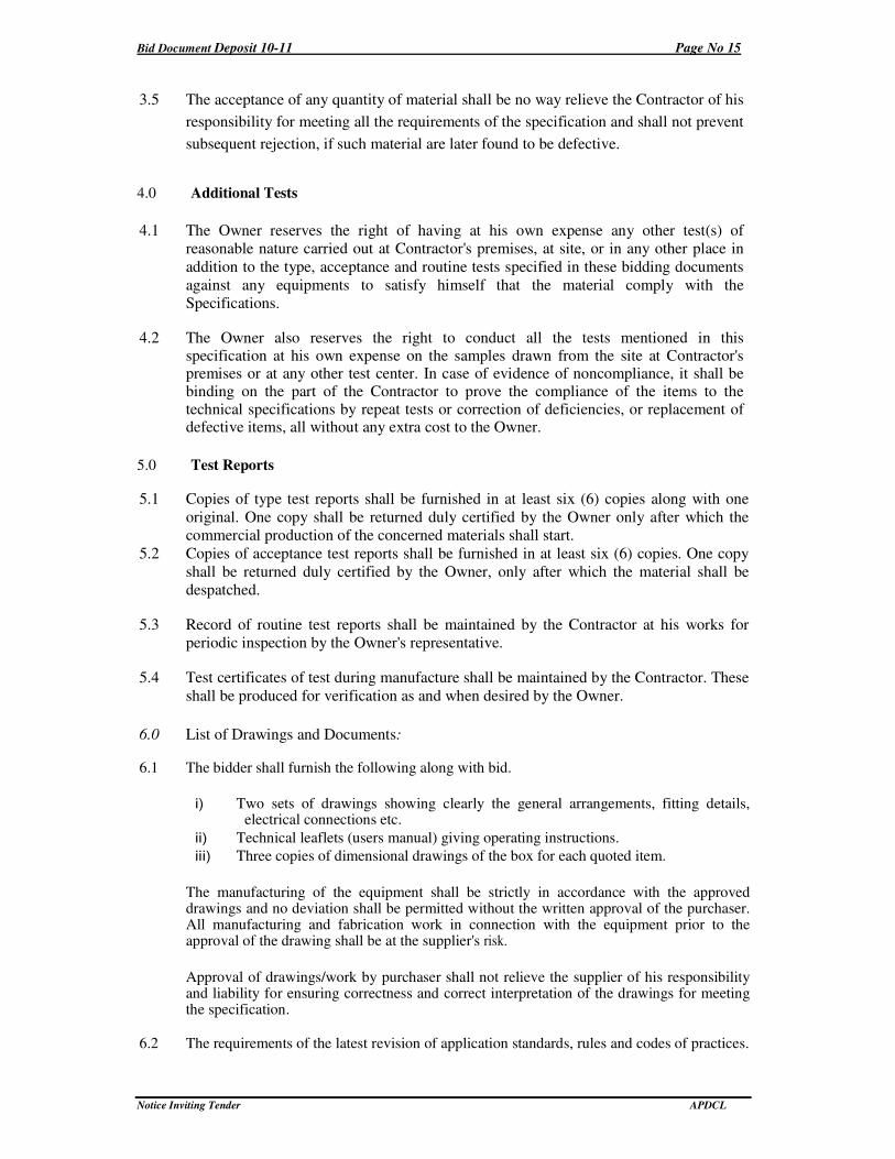
3.5 The acceptance of any quantity of material shall be no way relieve the Contractor of his
responsibility for meeting all the requirements of the specification and shall not prevent
subsequent rejection, if such material are later found to be defective.
4.0 Additional Tests
4.1 The Owner reserves the right of having at his own expense any other test(s) of
reasonable nature carried out at Contractor's premises, at site, or in any other place in
addition to the type, acceptance and routine tests specified in these bidding documents
against any equipments to satisfy himself that the material comply with the
Specifications.
4.2 The Owner also reserves the right to conduct all the tests mentioned in this specification at his own expense on the samples drawn from the site at Contractor's premises or at any other test center. In case of evidence of noncompliance, it shall be binding on the part of the Contractor to prove the compliance of the items to the technical specifications by repeat tests or correction of deficiencies, or replacement of defective items, all without any extra cost to the Owner.
5.0 Test Reports
5.1 Copies of type test reports shall be furnished in at least six (6) copies along with one
original. One copy shall be returned duly certified by the Owner only after which the
commercial production of the concerned materials shall start.
5.2 Copies of acceptance test reports shall be furnished in at least six (6) copies. One copy
shall be returned duly certified by the Owner, only after which the material shall be
despatched.
5.3 Record of routine test reports shall be maintained by the Contractor at his works for
periodic inspection by the Owner's representative.
5.4 Test certificates of test during manufacture shall be maintained by the Contractor. These
shall be produced for verification as and when desired by the Owner.
6.0 List of Drawings and Documents:
6.1 The bidder shall furnish the following along with bid.
i) Two sets of drawings showing clearly the general arrangements, fitting details, electrical connections etc.
ii) Technical leaflets (users manual) giving operating instructions.
iii) Three copies of dimensional drawings of the box for each quoted item.
The manufacturing of the equipment shall be strictly in accordance with the approved drawings and no deviation shall be permitted without the written approval of the purchaser. All manufacturing and fabrication work in connection with the equipment prior to the approval of the drawing shall be at the supplier's risk.
Approval of drawings/work by purchaser shall not relieve the supplier of his responsibility and liability for ensuring correctness and correct interpretation of the drawings for meeting the specification.
6.2 The requirements of the latest revision of application standards, rules and codes of practices.
Bid Document Deposit 10-11 Page No 16
Notice Inviting Tender APDCL
The equipment shall conform in all respects to high standards of engineering, design,
workmanship and latest revisions of relevant standards at the time of ordering and purchaser
shall have the power to reject any work or materials which, in his judgment is not in full
accordance therewith.
6.3 The successful Bidder shall within 2 weeks of notification of award of contract submit three
sets of final versions of all the drawings as stipulated in the purchase order for purchaser's
approval. The purchaser shall communicate his comments/approval on the drawings to the
supplier within two weeks. The supplier shall, if necessary, modify the drawings and
resubmit three copies of the modified drawings for their approval. The supplier shall within
two weeks. Submit 30 prints and two good quality report copies of the approved drawings
for purchaser's use.
6.4 Eight sets of operating manuals/technical leaflets shall be supplied to each consignee for the first instance of supply.
6.4.1 One set of routine test certificates shall accompany each dispatch consignment.
6.4.2 The acceptance test certificates in case pre-dispatch inspection or routine test certificates in
cases where inspection is' waived shall be got approved by the purchasers.
7.0 Any Item specification if not available in this document Contractor shall supply and execute the items meeting the relevant IS specification with the approval of the purchaser
Bid Document Deposit 10-11 Page No 17
Notice Inviting Tender APDCL
1.0 TECHNICAL SPECIFICATION FOR EXECUTION OF
WORK (FOR 33KV/11KV & LT LINES)
1.0 SCOPE : ERECTION OF 33 KV LINES WITH GITP-SP76 & 9.75 M,
PSC POLES
The scope covers the survey of the proposed route, tree clearance wherever necessary
transport of materials to the locations, erection of the line testing of the line and
handing over to the APDCL(CAZ) as per specification. Materials such as steel, cement,
PSCC Poles, top cleats, clamps, washers, earth wires, HBG metal, sand, water, cost of
bolts and nuts etc., as given in Annexure-1 are to be procured by the contractor cost of
which shall be included in the bid.
2.0 General :
The Contractor should be well acquainted with the IE Rules 1956 as
amended from time to time and with the Indian Telegraph Act 1889 so that
necessary provisions therein may be followed.
3.0 SURVEY OF THE RUTE
The Tentative route map of the line to be erected will be furnished by the
APDCL(CAZ) to the Contractor along with the copy of the concluded agreement.
The Contractor is required to carry out the detailed survey of the route of the line and
fix up the locations at the average span indicated in the schedule and mark the locations
and submit a detailed route map to the Engineer in charge of the work within 30 days
for approval. In the course of surveying by the contractor, any conspicuous variations in
the change and physical feature to those indicated in the route map and as actually
existing are noticed, the deviations must be brought to the notice of the APDCL(CAZ)
Engineer. The APDCL(CAZ) Engineer if considered necessary shall make alterations,
which shall be carried out accordingly and the APDCL(CAZ) after inspecting the
surveyed route and the revised route map shall be given for final approval in writing.
The contractor shall not commence the work until the final approval of the route map is
given by the Engineer in charge in writing to the contractor.
4.0 WAY LEAVES AND TREE CUTTINGS
Proposals for way leaves and right of way shall be submitted by the contractor.
Permission will be obtained by the APDCL(CAZ) within reasonable time for which due
notice shall be given by the Contractor. The Contractor shall arrange for tree cutting or
tree branches cutting also.
The widths of tree clearance to be adopted for lines of various voltages are as detailed
below:
Bid Document Deposit 10-11 Page No 18
Notice Inviting Tender APDCL
a) 11 KV / 33 KV LINE (Trunk Line)
All growth within 6.096 M (20 ft) from the center line of support and all trees which
may fall and foul the line.
The Contractor shall take all possible steps to see that standing crops, etc. are not
damaged while attending to tree cutting. When such damage is inevitable the
compensation will be borne by the APDCL(CAZ) provided the damage is with the
prior concurrence of the Engineer. The Contractor shall bear the compensation for
damage caused by the gangs without prior concurrence of the Engineer concerned.
No trees shall be cut until the APDCL(CAZ) has made necessary arrangement with
the authorities concerned and permission is given to the Contractor to fell such trees.
The contractor shall arrange to remove the obstacles as soon as possible.
At such times, when it may not possible for APDCL(CAZ) to arrange right-of-way
for excavation of pole pits or erecting the poles of stringing the line, then at all such
times, the contractor shall shift his gangs to other areas. The rates quoted shall cover
all such contingencies and no extra payments shall be claimed for such
contingencies.
5.0 EXCAVATION OF POLE PITS, STAY PITS AND D.P. PITS 5.1 After the final survey of the line and after marking the pole locations with pegs,
excavation work has to be commenced in accordance to the approved route map.
Excavation is generally done by pick axes, crow V-bars and showers although some
times earth augers are used. Excavation of pole pits in very hard or rocky soil or in
rock beds, may involve blasting with suitable explosives. The pits for the supports are
excavated in the direction of the line as this will facilitate the erection of support are
excavated in the direction of the line as this will facilitate the erection of support, in
addition to giving greater lateral stability, the depth of the foundation to be excavated
for poles shall be in accordance with relevant sketch for the erection of pole or stay of
D.P. etc.
6.0 ERECTION OF SUPPORTS
After the excavation of pits is completed the supports to be erected may be brought to
the pits location. Then the pole may be erected inside the pit. Wooden support may be
utilized to facilitate lifting of the pole at the pit locations.
Before the pole is put into pit, RCC padding may be laid below the pole to increase the
surface contact between the pole and the soil. The padding will distribute the weight of
the pole uniformly on the soil.
Having lifted the pole, the same should be kept in a vertical position with the help of
manila rope of 25 mm dia using the rope as a temporary anchor.
As the poles are being erected say from the pole already erected to the next location
where the pole is being erected, the alignment of the poles are to be checked and set
Bid Document Deposit 10-11 Page No 19
Notice Inviting Tender APDCL
right by visual check. The verticality’s of the poles are to be checked with a spirit level
on both transverse and longitudinal directions.
Having satisfied that the verticality and alignment are all right, earth filling or
concreting is to be done.
In swampy and special locations, however, before earth filing, the poles are to be
concreted up to ground level of the pit.
After the poles have been set the temporary anchors are to be removed. The supports
shall be buried to a depth as per sketch enclosed.
7.0 ERECTION OF D.P. STRUCTURES FOR ANGLE LOCATIONS (FOR
33/11 KV LINES):
Generally, for angles of deviation more than 20° double pole structures of spacing 1.2
mts (4.0 ft) may be erected. The pits are to be excavated as per bisection of the angle of
deviation.
After the poles are erected, the horizontal / cross bracing should be fitted and the
supports held in a vertical position with the help of temporary guys of manila rope of at
least 25 mm dia. Ensuring that the poles are held in a vertical position (this can be
checked with a spirit level) the concreting of the poles with cement, granite chips of
size 20/30 mm mesh and sand in the ratio M400 conforming to ISS is to be done from
the bottom of the support to the ground level. Before lifting the pole in the pit, concrete
padding of not less than 75 mm thickness may be put for the distribution of the load of
the support on the soil.
After the concreting is done, the pit may be filled with earth after curing of the concrete
is completed.
Four stays along the line, two in each direction and two stays along the bisection of
angle of deviation are to be provided.
Stay concreting may be done with M 400 concrete mixture.
The D.P. shall be erected as per the sketch enclosed.
8.0 ANCHORING AND PROVIDING GUYS FOR SUPPORTS
Guys are to be provided to the supports at the following places (i) Angle locations, (ii)
Dead end locations, (iii) Tee-off points, (iv) Steep gradient locations to avoid uplifted
on the poles.
The installation of guy will involve the following works:
i) Excavation of pit and fixing of stay rod.
ii) Fastening guy wire to the support.
iii) Tightening guy wire and fastening to the anchor
Bid Document Deposit 10-11 Page No 20
Notice Inviting Tender APDCL
The marking of the guy pit for excavation, the excavation of pits and setting of the
anchor rod must be carefully carried out. The stay rod should be placed in the position
such that the angle of inclination of the rod with the vertical face of the point is 30°/45°
as the case may be. The concreting of the stay at the bottom should then be carried out.
The back filling and ramming must be well done thereafter, and allowed to set for at
least 7 days. The free end of the guy wire is passed through the eye of the anchor rod,
bent back parallel to the main portion of the guy and bound after inserting the G.I.
Thimble. The loop is protected by the G.I. Thimble, where it bears on the anchor rod.
Where the existence of guy wire proves hazardous, it should be protected with suitable
asbestos pipe, filled with concrete of about 2 mts length above the ground level, duly
painted with white and black stripe so that it may be visible at night. The turn buckle
shall be mounted at the pole end of the stay and guy wire so fixed that the eye bolt turn
buckle is half way in the working position, thus giving the maximum movement for
tightening or loosening.
Guy insulators are placed to prevent the lower part of the guy from becoming
electrically energized by a contact of the guy when the conductors snap and fall on
them of due leakage. No guy insulator shall be located less than 2.6 mts. from the
ground.
The anchoring and providing guys for supports (Single guy Bow guy fly guy) shall be
done as per sketch enclosed. Bow guy and fly guy shall be provided as per field
conditions.
9.0 FIXING OF CROSS ARMS INSULATORS
After the erection of supports and providing guys, the next step would be to mount the
cross arms on the support erected. The lineman should climb the support having
requisite tools with him and the cross arm is then tied to a hand line and pulled up by the
ground man and should station himself well to one side so that if any material drops
from the top of the pole it may not strike him. All the materials required should be lifted
or lowered by means of the hand line. In no case, the materials of the tools should be
dropped or thrown from the pole top.
The fixing of 33 KV, 11 KV and LT Cross arms shall be in accordance to spacing
detailed in Sketch. G.I. bolts and nuts and spring washers of good quality only shall be
used which will have to be procured by the contractor.
9.1 Back Clamps
The back clamps for fixing of the seating channels, “V” cross arms, horizontal
cross arms and top cleats will have to be procured by the contractor and shall be
in accordance with sketch enclosed and the clamp shall be fabricated with 75 X
8 mm M.S. Flat for 33 KV and 50 X 8 mm M.S Flat for 11 KV and LT.
9.2 Top Cleats
The top cleats shall be got fabricated with M.S. Channel of size 75 X 40 mm for
33 KV and 11 KV and shall be in accordance with sketch enclosed..
Bid Document Deposit 10-11 Page No 21
Notice Inviting Tender APDCL
10.0 INSULATORS
The pins for insulators shall be fixed in the holes provided in the cross arms and the
pole top brackets. The insulators shall be mounted in their places over pins and
tightened. In the case of strain or angles supports, where strain fittings are provided
for this purpose, one strap of the strain fitting is placed over the cross arm before
placing the bolts in the hole of the cross arms. The nut of the strap is so tightened
that the strap can move freely in horizontal direction, as this is necessary to fix the
strain insulator.
The insulator shall be cleaned and examined for defects before fixing, it shall be
ensured that all the current carrying parts are smooth and without dirt, cracks or
chips.
11.0 STRINGING OF THE LINE CONDUCTORS
11.1 For the guidance of the contractor certain do’s and don’ts are given below before the
workmen actually commence the stringing work.
11.2 Do’s and Don’ts
DO’s
i. Use proper equipment for handling aluminum conductors at all times.
ii. Use skids, or similar method for lowering reels or coils from
transport or ground.
iii. Examine reel before unreeling for presence of nails or any other
object, which might damage the conductor.
iv. Rotate the reel or coil while unwinding conductor.
v. Grip all strands while pulling out the conductor.
vi. Control the unreeling speed with suitable braking arrangement.
vii. Use wooden guards of suitable braking arrangement.
viii. Use long straight, parallel jaw grip with suitable liners when pulling
conductor thus avoiding nicking or kinking of the conductor.
ix. Use free running sleeves or blocks with adequate grooves for
drawing/paving conductors.
x. Use proper sag charts.
xi. Mark conductors with crayons or adhesive tape of such (other)
material, which will not damage the strand.
xii. Make all splicing with the proper tools.
xiii. Use a twisting wrench for twisting the joints.
xiv. Chromite or graphite conducting oxide-inhibiting grease should be
used before cleaning with wire brush.
DON’Ts
i. Do not handle conductors without proper tools at any stage.
ii. Do not pull conductors without ensuring that there are no
obstructions on the ground.
iii. Do not pull out excess quantity of conductor than is required.
iv. Do not make jumper connections on dirty or weathered conductor.
Bid Document Deposit 10-11 Page No 22
Notice Inviting Tender APDCL
v. Do not handle aluminum conductors in a rough fashion but handle it
with care it deserves.
11.3 CONDUCTOR ERECTIONS
The erection of overhead line conductor is a very important phase in construction.
The erection of conductors can be sub-divided into 4 separate parts as follows:
i. Transport of conductors to work site.
ii. Paving and stringing of conductors.
iii. Tensioning and sagging of conductors.
iv. Joining of conductors.
At the important crossing of roads, canals, navigable rivers, railways etc., flagmen
should be in attendance to ensure that normal services are not unduly interrupted.
These crossing should only be carried out in conjunction with and with the approval
of the proper authorities concerned.
The conductor drums shall be transported to the tension point without injuring the
conductor, if, it is necessary to roll the drum on the ground for a small distance, it
should be slowly rolled in the direction of the marked on the drum. The drum should
be so supported that it can be rotated freely. For this purpose the drum should either
be mounted on the cable drum supports of jacks or hung by means of chain pulley of
suitable capacity, suspended from a tripod. In case if it is not possible to raise the
conductor drum by any of the above method, a trench of suitable depth slightly
bigger than the conductor drum may be dug, so as to facilitate free rotation of the
cable drum when it is suspended in the trench by means of M.S. Shaft. While
paving, care should be taken to see that conductor does not rub against any metallic
fitting of the pole or on the bad/rocky ground. Wooden trusses should be used for
this purpose to support the conductor. The conductor should be passed over the
poles on wooden or aluminum snatch pulley blocks provided with low friction
bearings. While conductor is being paved out slowly, some braking arrangement
should be made so that the rotation of the drum may be stopped in emergency.
In case the length of one piece of the conductor is less than the length of the section
in which conductor paving is being done, it is easy to stretch one length of all phases
from one end the remaining length from another end of the section any part of the
conductor shall be left at a height of less than that of 5 meters, above the ground by
rough sagging.
11.4 Mid Span Jointing of Conductors
The mid span jointing of conductors can be carried by twisting the joint at the ends
and the wire should project a few centimeter, beyond the end of the sleeves. The
projected wires are given a sharp bend to keep them from slipping out of the sleeve.
The end of the sleeves are then held tightly by twisting wrenches and then 4 to 5
turns in one direction generally anti-clock wise direction. Crimping Tools are
preferably to be used for joints and jumpers.
11.5 SAGGING AND TENSIONING
Bid Document Deposit 10-11 Page No 23
Notice Inviting Tender APDCL
On the completion of the paving of the conductors and making mid span joints if
any, tensioning operations will commence. Temporary guys will have to be provided
for both the anchoring supports in the section where the stringing has to be done. At
the tensioning end, one of the conductors is pulled manually up to a certain point
and then come along clamp is fixed to the conductor to be tensioned. The grip to the
come along clamp is attached to double sleeve pulley block or the pulley lift
machine and gradually tensioned.
The conductor should then be sagged in accordance with the sag temperature chart
for the particular conductor and span. The sag should then be adjusted in the middle
span of the section. The sag chart is to be provided. The stretch of the conductor has
to be taken out before stringing in order to avoid the gradual increase in sag due to
the setting down of the individual wires. There are ways of accomplishing this:
a) Pre-stressing
In this method the conductor is pulled up to tension considerably above the correct
figures, but never exceeding 50% of breaking load for a short period of say twenty
minutes. As this method requires more time and involves the use of stronger tackle
to secure the higher tension the other method of over tensioning is commonly
adopted.
b) Over-tensioning
This method consists of pulling up the conductor to a tension a little above the
theoretical tension for prevailing temperature and fixed it up at that tension with
correspondingly reduced sag. After a certain time the conductor will settle down to
the correct sag and tension. A tension of five to eight percent more than the
theoretical value has been found to be suitable for the sizes of ACSR and AAAC
conductors standardized by REC. The ambient temperature during sagging may be
recorded correctly.
Conductors can be sagged correctly only when the tension is the same in each span
throughout the entire length of section. Use of snatch blocks reduces the friction and
chances of inequality of tension in various spans.
Sagging can be accomplished by several different methods but most commonly used
method is “Slighting”. The slighting sag method of measuring sag is by the use of
targets placed on the supports below the cross arms. The targets may be light strip of
wood clamped to the pole at a distance equal to the sag below the conductor when
the conductor is placed in snatch block. The lineman sees the sag from the next pole.
The tension of the conductor is then reduced or increased, until the lowest part of the
conductor in the span coincides with the lineman’s line of sight.
When sagging is completed, the tension clamps shall be fixed. The clamp can be
fitted on the conductor without releasing the tension. A mark is made on the
conductor at a distance from the cross-arm equal to the length of complete strain
insulator. Before the insulator set is raised to position, all nuts should be free. Come
along clamp is placed on the conductor beyond the conductor clamp and attached to
the pulling unit. The conductor is pulled in sufficiently to allow the insulator
Bid Document Deposit 10-11 Page No 24
Notice Inviting Tender APDCL
assembly to be fitted to the clamp. After the conductor is clamped to insulator,
assembly unit may be released gradually.
If the tension is released with a jerk, an abnormal stress may be transferred to
conductor and support, which may result in the failure of the cross arm, stay or pole
in some cases. After the stringing is completed, all poles, cross arms, insulators,
fittings etc. are checked upto ensure that there have been no deformities etc.
The next step is to place the conductor on the top of the pin insulator from the snatch
block and removing snatch blocks. Conductors are then fastened to insulator by the
use of aluminum wires. The following points should be observed:
i) Proper size of the tie binding wire which can be readily handled and with
adequate strength is to be used.
ii) The length of tie wire should be sufficiently long for making complete tie
including the end allowances for gripping with ends.
iii) A good tie should provide a secure binding between the line conductor and
insulator and should reinforce the conductor on either side of the insulator.
iv) The use of cutting pliers for binding the tie wire should be avoided.
v) The tie wire which has been used previously should be reused
Before tying the conductor to the insulator two layers of Aluminum tapes should be
wrapped over the conductor in the portion where it touches the insulator. The width
and thickness of aluminum tape to be used for a specific size of conductors has been
specified in hand books of aluminum conductor manufacturers and the same be
referred to. The Aluminum tapes should also be used at the tension clamp and for
proper grip.
Normally in straight runs of line, the conductors are run on the top of insulators.
When there is small of deviation the conductor is placed inside groove and bound.
Accordingly, there are two methods of tying the conductors to insulators. The
binding wire/tie wire has to be procured by the contractor and the bid price shall
include the cost of this.
11.6 The contractor shall be entirely responsible for any damage to the supports, other
accessories and conductor. He shall also be responsible for proper distribution of the
conductor drums to keep number and lengths of cut pieces of the conductor to a
minimum.
11.7 CONDUCTOR DAMAGE AND REPAIR
If the conductor is damaged for whatever reasons, and damage is not repaired by
aluminum sleeves, etc., it shall be brought to the notice of the Engineer and shall not
be used without his approval. Even repairing of conductor surfaces shall be done
only in case of minor damages, scuff marks etc., which are safe from both electrical
and mechanical points of view. The final; conductor surface shall be clean, smooth,
without any projection sharp points, cut or abrasion etc. giving satisfactory corona
and R.I. performance.
Bid Document Deposit 10-11 Page No 25
Notice Inviting Tender APDCL
11.8 No joints or splice be made in span’s crossing over main roads, railways, small rivers
or intension spans. Not more than one joint per conductor shall be allowed in one span.
The strength of the joint shall conform to IE Rule 75.
11.9 STRINGING.
Whatever necessary ground clearances have to be measured to ensure obtaining
adequate line clearance as per IE Rule 77 (i)
12.0 EARTHING
12.1 Pipe Earthing
At D.P Locations, Pits are to be excavated the steel and metal parts are to be earthed
by pipe earthing as per the drawing or sketch enclosed to this specification. Duly
filling the pits with finely broken coke having granule sizes not more than 25 mm
thick. The coke shall be maintained up to a distance of 300 mm for the pipe on all
sides. The top edge of the pipe shall be at least 200 mm below the ground level. The
CI strips shall be fixed not less than 300 mm deep from the ground level.
The tenders shall quote the charges for earthing inclusive of the cost of coke,
excavation and back filling.
12.2 Pole Earthing: Supports shall be properly earthed.
13.0 CONCRETING
13.1 The cement concrete used for the foundations shall be of M 400 grade.
13.2 The full concreting for the poles if erected in excavated act shall be done
so that the complete block will be of dimensions( 0.6 X 0.6 X 1.6) + 0.2
X 0.2 Mtr. (0.6 X 0.6 X 1/35) + 0.2 X 0.2 X 0.2 Mtrs. so as to maintain
as exposed portion for 0.2 Mtrs height above the ground level.
13.3 If augur is used for making pole pits, ramming shall be done after
erection of pole.
14.0 WORKMANSHIP
The contractor shall entirely be responsible for correct erection of all support as per
the approved drawings, and their correct setting and alignment, as approved by the
engineer. If the supports and D.P. structures after the erection are found to differ
from approved route maps and drawings or to be out of alignment, the contractor
shall dismantle and re-erect them correctly at his own cost without extension of
time. The supports must be truly vertical and in plumb after erection and no straining
will be permitted to bring them to vertical position. Verticality of each support shall
be measured by the contractor and furnished to the Engineer.
Bid Document Deposit 10-11 Page No 26
Notice Inviting Tender APDCL
15.0. Location numbers for each pole shall be painted on the pole.
Anti-climbing devices, and danger boards are to be provided at all railway crossings
and road crossings. No extra charges shall be admissible even though separate gangs
may have to be sent by the contractor for fitting these accessories and attachments
on the support at the appropriate time.
16.0. FINAL CHECKING, TESTING AND COMMISSIONING
After the completion of the work final patrolling and checking of the line shall be
done by the contractor to ensure that all foundations work, pole erection and
stringing have been done as approved by the Engineer, and also to ensure that they
are completed in all respects. Contractor shall prepare pole schedules and hand it
over to the Engineer. All works shall be thoroughly inspected keeping in view of the
following main points.
i) Sufficient back filled earth is lying over each foundation pit and it is
adequately compacted.
ii) Concreting and coping of poles are in good and finally shaped conditions.
iii) All the accessories and insulators are strictly as per drawings and are free
from any defects or damages, what-so-ever.
iv) All the bolts and nuts should be of G.I material and as per contractual
provisions.
v) The stringing on the conductor has been done as per approved sag and
desired clearances are available.
vi) No damage, minor or major to the conductor, earth wire, accessories and
insulator strings still unattended are noticed.
vii) For all points double jumpers shall be provided to each phase. The jumpers
provided at the cut points are connected rigidly to the tension hardware
utilizing all the jointing bolts provided for the purpose.
The contractor shall submit a report to the above effect to the Engineer. In case, it is
noticed later that some or any of the above are not fulfilled the Engineer will get
such items rectified through other agencies and recover the cost of such works from
the bills payable to the contractor against that contract or any other contract executed
by him for APDCL(CAZ).
After final checking, the lines shall be tested for insulation in accordance with tests
prescribed by the Engineer. All arrangements for such testing or any other tests
desired by the Engineer shall be done by the Contractor and necessary labour,
transport and equipment shall be provided by him. Any defects found out as a result
of such tests, shall be rectified by the Contractor, forthwith, without any extra
charges to APDCL(CAZ).
In addition to the above, the Contractor shall be responsible for testing and ensuring
that the total and relative sags of the conductors are within the specified tolerance.
Such tests shall be carried out at selected points along the route as required by the
Engineer and the Contractor shall provide all necessary equipment and labour to
enable the tests to be carried out.
Bid Document Deposit 10-11 Page No 27
Notice Inviting Tender APDCL
The APDCL(CAZ) will arrange statutory inspection of the line and indicate the
defects noticed. The Contractor has to rectify all such defects and intimate to
APDCL(CAZ) Engineer.
After satisfactory tests on the line and an approval by the Engineer the line shall be
energized at full operating voltage before handing over.
17.0. SUPPLY OF CONSTRUCTION MATERIALS BY THE
CONTRACTOR
The Contractor has to make his own arrangements for procurement, supply and use
of construction materials like cement, M.S. rounds, HBG metal and sand.
17.1. CEMENT
The contractor has to make his own arrangements for the procurement of cement to
require specifications required for the work subjected to the follows:
a) The contractor shall procure cement, required for the works only from reputed
cement factories (Man producer) acceptable to the Engineer-in-Charge. The
contractor shall be required to be furnished to the Engineer-in –Charge bills of
payment and test certificates issued by the manufacturers to authenticate
procurement of quality cement from the approved cement factory. The contractor
shall make his own arrangement for adequate storage of cement.
b) The contractor shall procure cement in standard packing of all 50 kg per bag from
the authorized manufactures. The contactor shall make necessary arrangement at his
own cost to the satisfaction of Engineer-in-Charge for actual weighment of random
sample from the available stock and shall conform to the specification laid down by
the Indian Standard Institution or other standard foreign institutions as the case may
be. Cement shall be got tested for all the tests as directed by Engineer-in-Charge at
least one month in advance before the use of cement hags brought and kept on site
Godown. Cement bags required for testing shall be supplied by the contractor free of
cost. However, the testing charges for cement will be borne by the APDCL(CAZ). If
the tests prove unsatisfactorily, then the charges for cement will be borne by the
contractor.
c) The contractor should store the cement of 60 days requirement at least one month
in advance to ensure the quality of cement so brought to site and shall not remove
the same without the written permission of the Engineer-in-Charge.
The contractor shall forthwith remove from the works area any cement that the
Engineer-in-Charge may disallow for use, an account of failure to meet with
required quality and standard.
d) The contractor shall further, at all times satisfy the Engineer-in-Charge on
demand, by production of records and books or by submission of returns and other
proofs as directed, that the cement is being used as rested and approved by Engineer-
in-Charge for the purpose and the contractor shall at all times, keep his records upto
date to enable the Engineer-in-Charge to apply such checks as he may desire.
Bid Document Deposit 10-11 Page No 28
Notice Inviting Tender APDCL
e) Cement which has been unduly long in storage with the contractor or
alternatively has deteriorated due to inadequate storage and thus become unfit for
use in the works will be rejected by the department and no claim will be entertained.
The contractor shall forthwith remove from the work area, any cement the Engineer-
in-Charge may disallow for use on work and replace it by cement complying with
the relevant Indian Standards.
17.2. STEEL
The contractor shall procure mild steel reinforcement bars, high yield strength
deformed(HYSD) bars, rods and structural steel etc. required for the works only
from the main or secondary producers manufacturing steel to the prescribed
specifications of Bureau of Indian Standards or equivalent and licensed to affix ISI
or other equivalent certification marks and acceptable to the Engineer-in-Charge.
Necessary ISI list certificates are to be produced to Engineer-in-Charge before use
on works. The unit weight and dimensions shall be as prescribed in the relevant
Indian Standard specification for steel.
18.0. INFORMATION AND DATA
a) The information furnished is the best available however, the APDCL(CAZ) does
not guarantee the correctness of interpretations, deductions or conclusions which
are given as supplementary information in the Bid Documents or in any reports,
maps, drawings, diagrams or in other reference information available to the
bidder from APDCL(CAZ) of or otherwise.
The information has been produced as found, communicated to ascertained or
otherwise/learned by the APDCL(CAZ).
b) it will be the Bidder’s responsibility to satisfy himself from the “Reference
Information” supplied and or inspection of the site that sufficient quantities of
construction materials required for the works shall exist in the designated borrow
areas or quarry sites.
The APDCL(CAZ) does not accept any responsibility either in handing over the
quarries or procuring the materials or any other facilities. The Tenderer will not
be entitled for any extra rate or claim for the misjudgment on his part for the
quantity and quality of materials available in the quarries.
Failure by the Bidder to have done all the timings which is in accordance with
this condition he is deemed to have done shall not relieve the successful Bidder
of the responsibility for satisfactorily completing the work as required at the
rates quoted by him.
Bid Document Deposit 10-11 Page No 29
Notice Inviting Tender APDCL
2.0 TECHNICAL SPECIFICATION FOR POLES OF : 33 KV
OVERHEAD POWER LINES
1.0 SCOPE
This covers supply of poles, insurance, storage, erection and commissioning of poles.
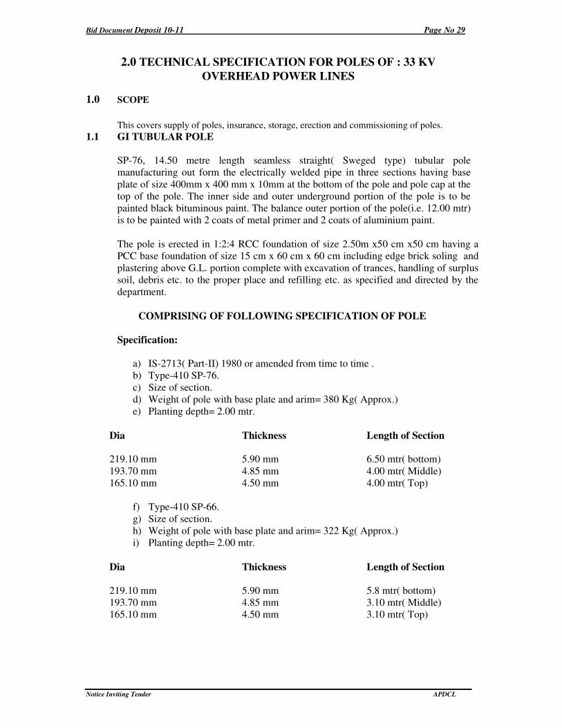
1.1 GI TUBULAR POLE
SP-76, 14.50 metre length seamless straight( Sweged type) tubular pole
manufacturing out form the electrically welded pipe in three sections having base
plate of size 400mm x 400 mm x 10mm at the bottom of the pole and pole cap at the
top of the pole. The inner side and outer underground portion of the pole is to be
painted black bituminous paint. The balance outer portion of the pole(i.e. 12.00 mtr)
is to be painted with 2 coats of metal primer and 2 coats of aluminium paint.
The pole is erected in 1:2:4 RCC foundation of size 2.50m x50 cm x50 cm having a
PCC base foundation of size 15 cm x 60 cm x 60 cm including edge brick soling and
plastering above G.L. portion complete with excavation of trances, handling of surplus
soil, debris etc. to the proper place and refilling etc. as specified and directed by the
department.
COMPRISING OF FOLLOWING SPECIFICATION OF POLE
Specification:
a) IS-2713( Part-II) 1980 or amended from time to time .
b) Type-410 SP-76.
c) Size of section.
d) Weight of pole with base plate and arim= 380 Kg( Approx.)
e) Planting depth= 2.00 mtr.
Dia Thickness Length of Section
219.10 mm 5.90 mm 6.50 mtr( bottom)
193.70 mm 4.85 mm 4.00 mtr( Middle)
165.10 mm 4.50 mm 4.00 mtr( Top)
f) Type-410 SP-66.
g) Size of section.
h) Weight of pole with base plate and arim= 322 Kg( Approx.)
i) Planting depth= 2.00 mtr.
Dia Thickness Length of Section
219.10 mm 5.90 mm 5.8 mtr( bottom)
193.70 mm 4.85 mm 3.10 mtr( Middle)
165.10 mm 4.50 mm 3.10 mtr( Top)
Bid Document Deposit 10-11 Page No 30
Notice Inviting Tender APDCL
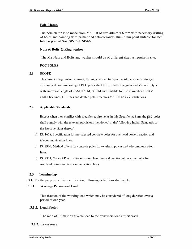
Pole Clamp
The pole clamp is to made from MS Flat of size 40mm x 6 mm with necessary drilling
of holes and painting with primer and anti-corrosive aluminium paint suitable for steel
tubular pole of Size SP-76 & SP-66.
Nuts & Bolts & Ring washer
The MS Nuts and Bolts and washer should be of different sizes as require in site.
PCC POLES
2.1 SCOPE
This covers design manufacturing, testing at works, transport to site, insurance, storage,
erection and commissioning of PCC poles shall be of solid rectangular and Virendeel type
with an overall length of 7.5M, 8.50M, 9.75M and suitable for use in overhead 33KV
and11 KV lines, L T lines and double pole structures for 11/0.433 kV substations.
2.2 Applicable Standards
Except when they conflict with specific requirements in this Specific ht: 8nm, the psc poles
shall comply with the relevant provisions mentioned' in the' following Indian Standards or
the latest versions thereof.
a) IS: 1678, Specification for pre-stressed concrete poles for overhead power, traction and
telecommunication lines.
b) IS: 2905, Method of test for concrete poles for overhead power and telecommunication
lines.
c) IS: 7321, Code of Practice for selection, handling and erection of concrete poles for
overhead power and telecommunication lines.
2.3 Terminology
.3.1. For the purpose of this specification, following definitions shall apply:
.3.1.1. Average Permanent Load
That fraction of the working load which may be considered of long duration over a
period of one year.
.3.1.2. Load Factor
The ratio of ultimate transverse load to the transverse load at first crack.
.3.1.3. Transverse
Bid Document Deposit 10-11 Page No 31
Notice Inviting Tender APDCL
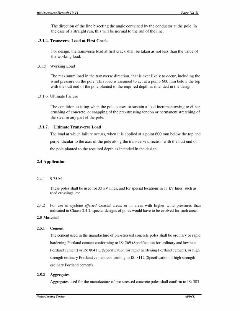
The direction of the line bisecting the angle contained by the conductor at the pole. In
the case of a straight run, this will be normal to the run of the line.
.3.1.4. Transverse Load at First Crack
For design, the transverse load at first crack shall be taken as not less than the value of
the working load.
.3.1.5. Working Load
The maximum load in the transverse direction, that is ever likely to occur, including the
wind pressure on the pole. This load is assumed to act at a point· 600 mm below the top
with the butt end of the pole planted to the required depth as intended in the design.
.3.1.6. Ultimate Failure
The condition existing when the pole ceases to sustain a load incrementowing to either
crushing of concrete, or snapping of the pre-stressing tendon or permanent stretching of
the steel in any part of the pole.
.3.1.7. Ultimate Transverse Load
The load at which failure occurs, when it is applied at a point 600 mm below the top and
perpendicular to the axis of the pole along the transverse direction with the butt end of
the pole planted to the required depth as intended in the design.
2.4 Application
2.4.1 9.75 M
These poles shall be used for 33 kV lines, and for special locations in 11 kV lines, such as
road crossings, etc.
2.4.2 For use in cyclone affected Coastal areas, or in areas with higher wind pressures than
indicated in Clause 2.4.2, special designs of poles would have to be evolved for such areas.
2.5 Material
2.5.1 Cement
The cement used in the manufacture of pre-stressed concrete poles shall be ordinary or rapid
hardening Portland cement conforming to IS: 269 (Specification for ordinary and low heat
Portland cement) or IS: 8041 E (Specification for rapid hardening Portland cement), or high
strength ordinary Portland cement conforming to IS: 8112 (Specification of high strength
ordinary Portland cement).
2.5.2 Aggregates
Aggregates used for the manufacture of pre-stressed concrete poles shall confirm to IS: 383
Bid Document Deposit 10-11 Page No 32
Notice Inviting Tender APDCL
(Specification for coarse and fine aggregates from natural sources for concrete). The
nominal maximum size of aggregates shall in no case exceed 10 mm (for poles above 9.0
M) .
2.5.3 Water
Water should be free from chlorides, sulphates, other salts and organic matter, Potable
water will be generally suitable.
2.5.4 Admixture
Admixture should not contain Calcium Chloride or other chlorides and salts which are
likely to promote corrosion of pre-stressing steel.
2.5.5 Pre-stressing Steel
,
The pre-stressing steel wires including those used as un-tensioned wires (See Annexure. I, II & III), should conform to IS: 1785 (part-I) (Specification for plain hard-drawn steel wire for pre-stressed concrete. Part-I cold drawn stress relieved wire), IS: 1785 (part-II) (Specification for plain hard-drawn steel wire) or IS: 6003 (Specification for indented wire for pre-stressed concrete). The type designs given in Annexure-I, II and III are for plain wires of 4 mm diameter with a guaranteed ultimate strength of 175 kg/mm2.
2.5.6 The concrete mix shall be designed to the requirements laid down for controlled concrete
(also called design mix concrete) in IS: 1343 (Code of practice for pre-stressed concrete)
and IS: 456 (Code of practice for plain and reinforced concrete), subject to the following
special conditions:
a) Maximum works cube strength at 28 days should be at least 400 kg/cm2 (for poles above 9.0
M) .
b) The concrete strength at transfer should be at least 200 kg/cm2 (for poles above 9.0 M) .
c) The mix should' contain at least 380 kg of cement per cubic meter of concrete.
d) The mix should contain as Iowa water content as is consistent with adequate workability. If
it becomes necessary to add water to increase the workability, the cement content also
should be raised in such a way that the original value of water cement ratio is maintained.
2.6 DESIGN REQUIREMENTS
The poles shall be designed for the following requirements:
a) The poles shall be planted directly in the ground with a planting depth as per IS:
1678.
b) The working load on the poles should correspond to those that are likely to come on the
pole during their service life. Designs given in Annexure I,ll and III are for 140 kg, 200
kg, 300 kg, and 400 kg., applied at 0.6 M from top.
Bid Document Deposit 10-11 Page No 33
Notice Inviting Tender APDCL
c) The factor of safety for all poles above 9.0 M shall not be less than 2.0. For 7.5 M and
8.5 M poles, the factor of safety shall not be less than 2.5.
d) The average permanent load shall be 40% of the working load.
e) The F.O.S. against first load shall be 1.0.
f) At average permanent load, permissible tensile stress in concrete shall be 30 kg/cm2.
g) At the design value of first crack load, the modulus of rupture shall not exceed 53.0
kg/cm2 for M-400 concrete and 55.2 kg/cm2 for M-420 concrete.
h) At the design value of first crack load, the modulus of rupture shall not exceed 53.0
kg/cm2 for M-400 concrete.
i) The ultimate moment capacity in the longitudinal direction should be at least one fourth of
that il1 the transverse direction.
j) The maximum compressive stress in concrete at the time of transfer of pre-stress should not
exceed 0.8 times the cube strength.
k) The concrete strength at transfer shall not be less than half the 28 days strength ensured in
the design, i.e., 400 x 0.5 = 200 kg/cm2 or 420 x 0.5 = 210 kg/cm2.
2.6.1 Service Conditions
PSCC poles have to be designed to suit the following climatic conditions:
a) Maximum temperature of air in shade 40°C
b) Minimum temperature of air in shade 2°C
c) Maximum temperature of air in sun 45°C
d) Maximum humidity 93%
e) Average number of thunder storm days per 45 Days
annum
f) Maximum rainfall per annum 3500 mm
g) Average rainfall per annum 2200 mm
h) Wind pressure 97.8 Kg/m2
i) Altitude above MSL 100 M to 1000 M
2.6.2 Dimensions and Reinforcements
The cross-sectional dimensions and the details of pre-stressing wires should conform to the particulars given in Annexure-I, II and III.
The provisions of holes for fixing cross-arms and other fixtures should conform to the REC standards referred to in clause 3.3 of this specification.
Bid Document Deposit 10-11 Page No 34
Notice Inviting Tender APDCL
2.0.3 Manufacture
2.0.3.1 Attire--stressing wires and reinforcements shall be accurately fixed as shown in drawings
and maintained in position during manufacture. The un-tensioned reinforcement, as
indicated in the drawings, should be held in position by the use of stirrups which should go
round all the wires.
2.6.3.2 AII wires shall be accurately stretched with uniform pre-stress in each wire. Each wire or a
group of wires shall be anchored positively during casing. Care should be taken to see that
the anchorages do not yield before the concrete attains the necessary strength.
2.6.4. Cover
The cover of concretE1 measured from the outside of pre-stressing tendon shall be normally
20 Nm.
2.6.5. Welding and Lapping of Steel
The high tensile steel wire shall be continuous over the entire length of the tendon. Welding
shall not be allowed in any case. However, jointing or coupling may be permitted provided
the strength of the joint or coupling is not less than the strength of each individual wire.
2.6.6. Compacting
Concrete shall be compacted by spinning, vibrating, shocking or other suitable mechanical
means. Hand compaction shall not be permitted.
2.6.7. Curing
The concrete shall be covered with a layer of sacking, canvass, Hessian or similar absorbent
material and kept constantly wet up to the time when the strength of concrete is at least
equal to the minimum strength of concrete at transfer of pre-stress. Thereafter, the pole may
be removed from the mould and watered at intervals to prevent surface cracking of the unit,
the interval should depend on the atmospheric humidity and temperature.
The pre-stressing wires shall be detensioned only after the concrete has attained the
specified strength at transfer (i.e., 200 or 210 kg/cm2 as applicable). The cubes cast for the
purpose of determining the strength at transfer should be cured, as far as possible, under
conditions similar to those under which the poles are cured. The transfer stage shall be
determined based on the daily tests carried out on concrete cubes till the specified strength
indicated above is reached. Thereafter the test on concrete shall be carried out as detailed in
IS: 1343 (Code of pr3ctice for pre-stressed concrete). The manufacturer shall supply, when
required by the owner or his representative, result of compressive test conducted in
accordance with IS: 456 (Code of practice for plain and reinforced concrete) on concrete
cubes made from the concrete used for the poles. If the owner so desired, the manufacturer
shall supply cubes for test purposes and such cubes shall be tested in accordance with IS:
456 (Code of practice for plain and reinforced concrete).
The detensioning shall be done by slowly releasing the wires, without imparting shock or
sudden load to the poles. The rate of detensioning may be controlled by any suitable means
either mechanical (screw type) or hydraulic.
The poles shall not be detensioned or released by cutting the pre-stressing wires using
Bid Document Deposit 10-11 Page No 35
Notice Inviting Tender APDCL
flames or bar croppers while the wires are still under tension.
2.6.8. Separate eye-hooks or holes shall be provided for handling the transport, one each at a
distance of 0.15 times the overall length, from either end of the pole. Eye-hooks, if
provided, should be properly anchored and should be on the face that has the shorter
dimension of the cross-section. Holes, if provided for lifting purposes, should be
perpendicular to the broad face of the pole.
Stacking should be done in such a manner that the broad side of the pole is vertical.
Each tier in the stack should be supported on timber sleeper located as 0.15 times the
overall length, measured from the end. The timber supported in the stack should be
aligned in a vertical line.
Poles should be transported with their broad faces placed vertically and, in such a
manner that the shocks are avoided. Supports should be so arranged that they are
located approximately at a distance equal to 0.15 times the overall length from the ends.
The erection of the pole should be carried out in such a way that the erection loads are
applied so as to cause moment with respect to the major axis, i.e., the rope used for
hoisting the pole should be parallel to the broader face of the pole.
2.6.9. Earthing
2.6.9.1 Earthing shall be provided by having length of 8 SWG GI wire embedded in concrete during manufacture and the ends of the wires left projecting from the pole to a length of 100 mm at 250 mm from top and 150 mm below ground level.
2.6.9.2 Earth wire shall not be allowed to come in contract with the pre-stressing wires.
2.7 Tests
2.7.1 Transverse Strength Test
2.7.1.1 Poles made from ordinary Portland cement shall be tested only on the completion of 28 days and poles made from rapid hardening cement only on the completion of 14 days, after the day of manufacture.
2.7.1.2 The poles may be tested in either horizontal or vertical position. If tested in horizontal position, provisions shall be made to compensate for the overhanging weight of the pole, for this purposed, the overhanging portion of the pole may be supported on a movable trolley or similar device.
2.7.1.3 The pole shall be rigidly supported at the butt end for a distance equal to the agreed
depth of planting.
2.7.1.4 Load shall be applied at a point 600 mm from the top of the pole and shall be steadily and
gradually increased to the design value of the transverse load at first crack. The deflection at
this load shall be measured.
A pre-stressed concrete pole shall be deemed not to have passed the test if visible cracks
appear at a stage prior to the application of the design transverse load for the first crack.
The load then be reduced to zero and increased gradually to a load equal to the first crack
load plus 10% of the minimum ultimate transverse load, and held up for 2 minutes. This
Bid Document Deposit 10-11 Page No 36
Notice Inviting Tender APDCL
procedure shall be repeated until the load reaches the value of 80 per cent of the minimum
ultimate transverse load and thereafter increased by 5 per cent of the minimum ultimate
transverse load until failure occurs. Each time the load is applied, it shall be held for 2
minutes. The load applied to pre-stressed concrete pole at the point of failure shall be
measured to the nearest five Kilograms.
The pole shall be deemed not to have passed the test if the observed ultimate transverse load
is less than the design ultimate transverse load.
2.7.1.5 Measurement of Cover
After completion of the transverse strength test, the sample pole shall be taken and checked
for cover. The cover of the pole shall be measured at 3 points, one within 1.8 meter from the
butt end of the pole. the ·second within 0.6 meters from the top and the third at an
intermediate point and the mean value compared with the specified value.
The mean value of the measured cover should not differ by more than (±) 1 mrn from the
specified cover. The individual values should ;Jot jiffer by more than (±) 3 mm from the
specified value.
If these requirements are not met, the workmanship with reference to aligning of the end
plates and pre-stressing wires and assembly of moulds should be improved and inspection
at pre-production stage tightened suitably.
3.0 MARKING
The pole shall be clearly and indelibly marked with the following particulars either during
or after manufacture but before testing at a position so as to be easily read after erection in
position.
a) Month and year of manufacture
b)Transverse strength of pole in Kg
4.0 INSPECTION
Inspection may be carried out by the purchaser or third party nominee at any stage of
manufacture. The supplier shall grant free access to the purchaser's representative or
third party nominee at a reasonable time when the work is in progress. Inspection and
acceptance of any equipment under this specification by the purchaser shall not relieve
the supplier of his obligation of furnishing equipment in accordance with the
specification and shall not prevent subsequent rejection if the equipment is found
defective.
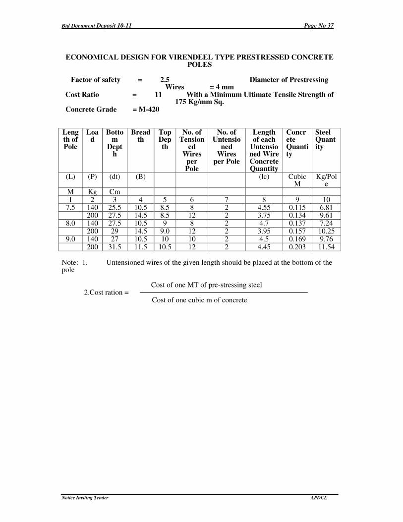
Bid Document Deposit 10-11 Page No 37
Notice Inviting Tender APDCL
ECONOMICAL DESIGN FOR VIRENDEEL TYPE PRESTRESSED CONCRETE POLES
Factor of safety = 2.5 Diameter of Prestressing
Wires = 4 mm Cost Ratio = 11 With a Minimum Ultimate Tensile Strength of
175 Kg/mm Sq. Concrete Grade = M-420
Length of Pole
Load
Bottom
Depth
Breadth
Top Depth
No. of Tension
ed Wires
per Pole
No. of Untensio
ned Wires
per Pole
Length of each
Untensioned Wire Concrete Quantity
Concrete Quantity
Steel Quantity
(L) (P) (dt) (B) (lc) Cubic M
Kg/Pole
M Kg Cm I 2 3 4 5 6 7 8 9 10
7.5 140 25.5 10.5 8.5 8 2 4.55 0.115 6.81 200 27.5 14.5 8.5 12 2 3.75 0.134 9.61
8.0 140 27.5 10.5 9 8 2 4.7 0.137 7.24 200 29 14.5 9.0 12 2 3.95 0.157 10.25
9.0 140 27 10.5 10 10 2 4.5 0.169 9.76 200 31.5 11.5 10.5 12 2 4.45 0.203 11.54
Note: 1. Untensioned wires of the given length should be placed at the bottom of the pole
Cost of one MT of pre-stressing steel 2.Cost ration =
Cost of one cubic m of concrete
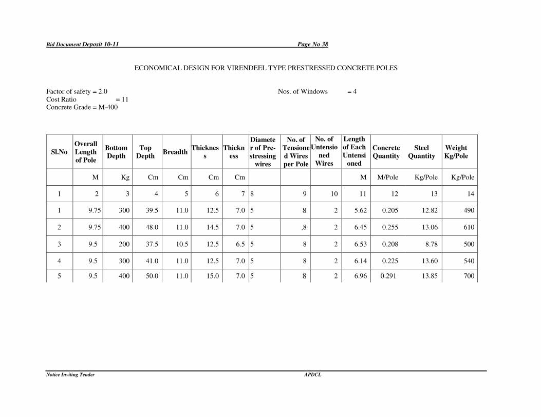
Bid Document Deposit 10-11 Page No 38
Notice Inviting Tender APDCL
ECONOMICAL DESIGN FOR VIRENDEEL TYPE PRESTRESSED CONCRETE POLES
Factor of safety = 2.0 Nos. of Windows = 4 Cost Ratio = 11 Concrete Grade = M-400
Sl.No
Overall
Length
of Pole
Bottom
Depth
Top
Depth Breadth
Thicknes
s
Thickn
ess
Diamete
r of Pre-
stressing
wires
No. of
Tensione
d Wires
per Pole
No. of
Untensio
ned
Wires
per Pole
Length
of Each
Untensi
oned
Wires
Concrete
Quantity
Steel
Quantity
Weight
Kg/Pole
M Kg Cm Cm Cm Cm M M/Pole Kg/Pole Kg/Pole
1 2 3 4 5 6 7 8 9 10 11 12 13 14
1 9.75 300 39.5 11.0 12.5 7.0 5 8 2 5.62 0.205 12.82 490
2 9.75 400 48.0 11.0 14.5 7.0 5 ,8 2 6.45 0.255 13.06 610
3 9.5 200 37.5 10.5 12.5 6.5 5 8 2 6.53 0.208 8.78 500
4 9.5 300 41.0 11.0 12.5 7.0 5 8 2 6.14 0.225 13.60 540
5 9.5 400 50.0 11.0 15.0 7.0 5 8 2 6.96 0.291 13.85 700
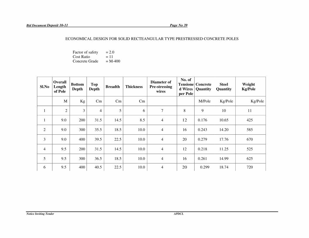
Bid Document Deposit 10-11 Page No 39
Notice Inviting Tender APDCL
ECONOMICAL DESIGN FOR SOLID RECTEANGULAR TYPE PRESTRESSED CONCRETE POLES
Factor of safety = 2.0 Cost Ratio = 11 Concrete Grade = M-400
Sl.No
Overall
Length
of Pole
Bottom
Depth
Top
Depth Breadth Thickness
Diameter of
Pre-stressing
wires
No. of
Tensione
d Wires
per Pole
Concrete
Quantity
Steel
Quantity
Weight
Kg/Pole
M Kg Cm Cm Cm M/Pole Kg/Pole Kg/Pole
1 2 3 4 5 6 7 8 9 10 11
1 9.0 200 31.5 14.5 8.5 4 12 0.176 10.65 425
2 9.0 300 35.5 18.5 10.0 4 16 0.243 14.20 585
3 9.0 400 39.5 22.5 10.0 4 20 0.279 17.76 670
4 9.5 200 31.5 14.5 10.0 4 12 0.218 11.25 525
5 9.5 300 36.5 18.5 10.0 4 16 0.261 14.99 625
6 9.5 400 40.5 22.5 10.0 4 20 0.299 18.74 720
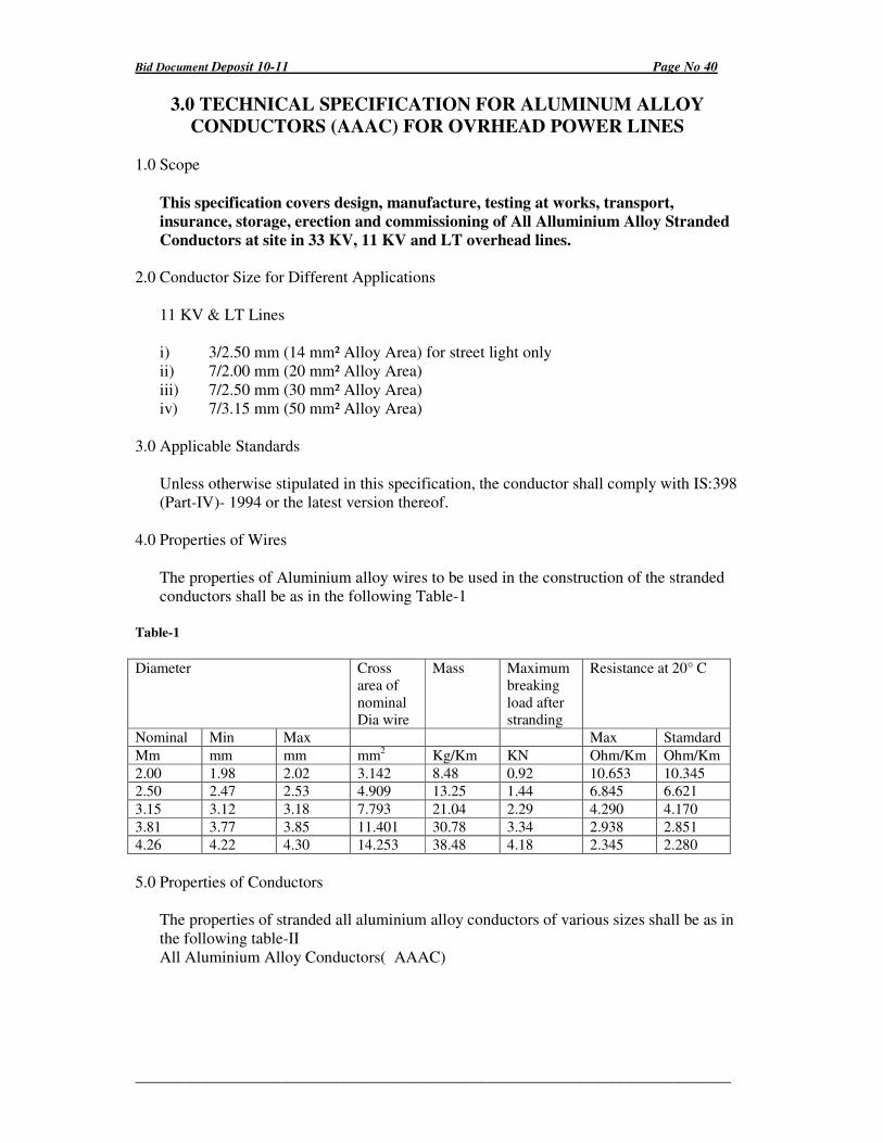
Bid Document Deposit 10-11 Page No 40
_________________________________________________________________________
3.0 TECHNICAL SPECIFICATION FOR ALUMINUM ALLOY
CONDUCTORS (AAAC) FOR OVRHEAD POWER LINES
1.0 Scope
This specification covers design, manufacture, testing at works, transport,
insurance, storage, erection and commissioning of All Alluminium Alloy Stranded
Conductors at site in 33 KV, 11 KV and LT overhead lines.
2.0 Conductor Size for Different Applications
11 KV & LT Lines
i) 3/2.50 mm (14 mm² Alloy Area) for street light only
ii) 7/2.00 mm (20 mm² Alloy Area)
iii) 7/2.50 mm (30 mm² Alloy Area)
iv) 7/3.15 mm (50 mm² Alloy Area)
3.0 Applicable Standards
Unless otherwise stipulated in this specification, the conductor shall comply with IS:398
(Part-IV)- 1994 or the latest version thereof.
4.0 Properties of Wires
The properties of Aluminium alloy wires to be used in the construction of the stranded
conductors shall be as in the following Table-1
Table-1
Diameter
Cross
area of
nominal
Dia wire
Mass Maximum
breaking
load after
stranding
Resistance at 20° C
Nominal Min Max Max Stamdard
Mm mm mm mm2 Kg/Km KN Ohm/Km Ohm/Km
2.00 1.98 2.02 3.142 8.48 0.92 10.653 10.345
2.50 2.47 2.53 4.909 13.25 1.44 6.845 6.621
3.15 3.12 3.18 7.793 21.04 2.29 4.290 4.170
3.81 3.77 3.85 11.401 30.78 3.34 2.938 2.851
4.26 4.22 4.30 14.253 38.48 4.18 2.345 2.280
5.0 Properties of Conductors
The properties of stranded all aluminium alloy conductors of various sizes shall be as in
the following table-II
All Aluminium Alloy Conductors( AAAC)
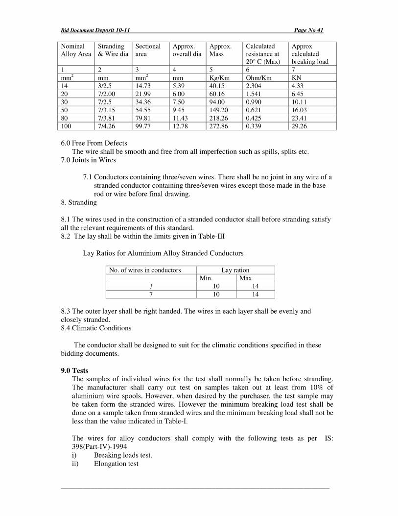
Bid Document Deposit 10-11 Page No 41
_________________________________________________________________________
Nominal
Alloy Area
Stranding
& Wire dia
Sectional
area
Approx.
overall dia
Approx.
Mass
Calculated
resistance at
20° C (Max)
Approx
calculated
breaking load
1 2 3 4 5 6 7
mm2 mm mm
2 mm Kg/Km Ohm/Km KN
14 3/2.5 14.73 5.39 40.15 2.304 4.33
20 7/2.00 21.99 6.00 60.16 1.541 6.45
30 7/2.5 34.36 7.50 94.00 0.990 10.11
50 7/3.15 54.55 9.45 149.20 0.621 16.03
80 7/3.81 79.81 11.43 218.26 0.425 23.41
100 7/4.26 99.77 12.78 272.86 0.339 29.26
6.0 Free From Defects
The wire shall be smooth and free from all imperfection such as spills, splits etc.
7.0 Joints in Wires
7.1 Conductors containing three/seven wires. There shall be no joint in any wire of a
stranded conductor containing three/seven wires except those made in the base
rod or wire before final drawing.
8. Stranding
8.1 The wires used in the construction of a stranded conductor shall before stranding satisfy
all the relevant requirements of this standard.
8.2 The lay shall be within the limits given in Table-III
Lay Ratios for Aluminium Alloy Stranded Conductors
No. of wires in conductors Lay ration
Min. Max
3 10 14
7 10 14
8.3 The outer layer shall be right handed. The wires in each layer shall be evenly and
closely stranded.
8.4 Climatic Conditions
The conductor shall be designed to suit for the climatic conditions specified in these
bidding documents.
9.0 Tests The samples of individual wires for the test shall normally be taken before stranding.
The manufacturer shall carry out test on samples taken out at least from 10% of
aluminium wire spools. However, when desired by the purchaser, the test sample may
be taken form the stranded wires. However the minimum breaking load test shall be
done on a sample taken from stranded wires and the minimum breaking load shall not be
less than the value indicated in Table-I.
The wires for alloy conductors shall comply with the following tests as per IS:
398(Part-IV)-1994
i) Breaking loads test.
ii) Elongation test
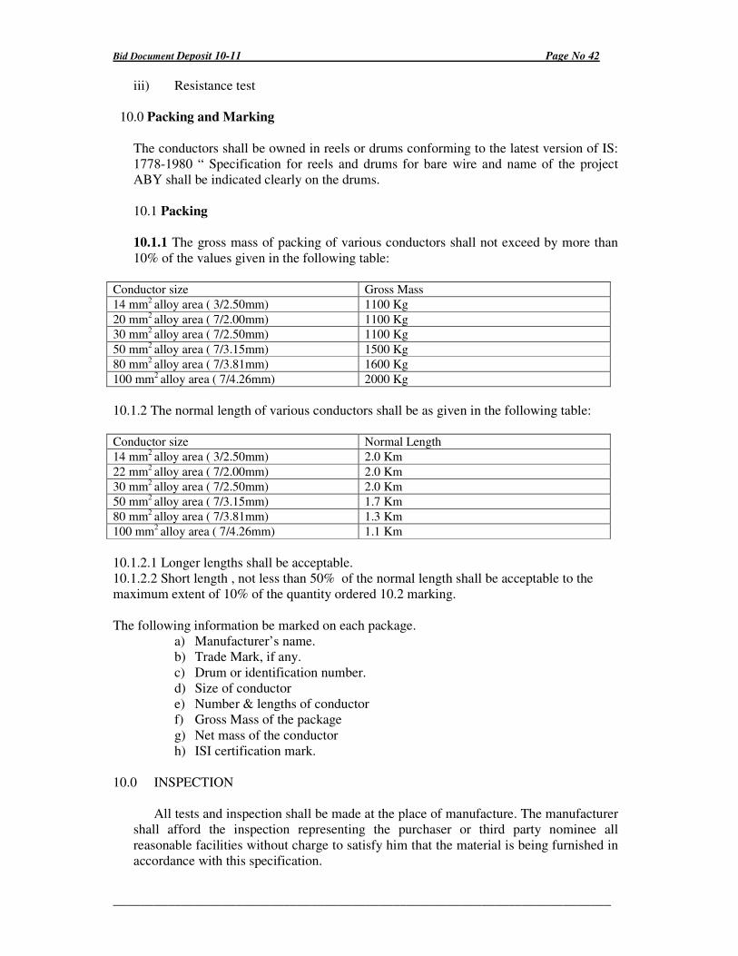
Bid Document Deposit 10-11 Page No 42
_________________________________________________________________________
iii) Resistance test
10.0 Packing and Marking
The conductors shall be owned in reels or drums conforming to the latest version of IS:
1778-1980 “ Specification for reels and drums for bare wire and name of the project
ABY shall be indicated clearly on the drums.
10.1 Packing
10.1.1 The gross mass of packing of various conductors shall not exceed by more than
10% of the values given in the following table:
Conductor size Gross Mass
14 mm2 alloy area ( 3/2.50mm) 1100 Kg
20 mm2 alloy area ( 7/2.00mm) 1100 Kg
30 mm2 alloy area ( 7/2.50mm) 1100 Kg
50 mm2 alloy area ( 7/3.15mm) 1500 Kg
80 mm2 alloy area ( 7/3.81mm) 1600 Kg
100 mm2 alloy area ( 7/4.26mm) 2000 Kg
10.1.2 The normal length of various conductors shall be as given in the following table:
Conductor size Normal Length
14 mm2 alloy area ( 3/2.50mm) 2.0 Km
22 mm2 alloy area ( 7/2.00mm) 2.0 Km
30 mm2 alloy area ( 7/2.50mm) 2.0 Km
50 mm2 alloy area ( 7/3.15mm) 1.7 Km
80 mm2 alloy area ( 7/3.81mm) 1.3 Km
100 mm2 alloy area ( 7/4.26mm) 1.1 Km
10.1.2.1 Longer lengths shall be acceptable.
10.1.2.2 Short length , not less than 50% of the normal length shall be acceptable to the
maximum extent of 10% of the quantity ordered 10.2 marking.
The following information be marked on each package.
a) Manufacturer’s name.
b) Trade Mark, if any.
c) Drum or identification number.
d) Size of conductor
e) Number & lengths of conductor
f) Gross Mass of the package
g) Net mass of the conductor
h) ISI certification mark.
10.0 INSPECTION
All tests and inspection shall be made at the place of manufacture. The manufacturer
shall afford the inspection representing the purchaser or third party nominee all
reasonable facilities without charge to satisfy him that the material is being furnished in
accordance with this specification.
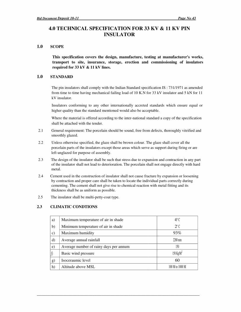
Bid Document Deposit 10-11 Page No 43
_________________________________________________________________________
4.0 TECHNICAL SPECIFICATION FOR 33 KV & 11 KV PIN
INSULATOR
1.0 SCOPE
This specification covers the design, manufacture, testing at manufacturer's works,
transport to site, insurance, storage, erection and commissioning of insulators
required for 33 kV & 11 kV lines.
1.0 STANDARD
The pin insulators shall comply with the Indian Standard specification IS : 731/1971 as amended
from time to time having mechanical failing load of 10 K.N for 33 kV insulator and 5 kN for 11
kV insulator.
Insulators conforming to any other internationally accreted standards which ensure equal or
higher quality than the standard mentioned would also be acceptable.
Where the material is offered according to the inter-national standard a copy of the specification
shall be attached with the tender.
2.1 General requirement: The porcelain should be sound, free from defects, thoroughly vitrified and
smoothly glazed.
2.2 Unless otherwise specified, the glaze shall be brown colour. The glaze shall cover all the
porcelain parts of the insulators except those areas which serve as support during firing or are
left unglazed for purpose of assembly.
2.3 The design of the insulator shall be such that stress due to expansion and contraction in any part
of the insulator shall not lead to deterioration. The porcelain shall not engage directly with hard
metal.
2.4 Cement used in the construction of insulator shall not cause fracture by expansion or loosening
by contraction and proper care shall be taken to locate the individual parts correctly during
cementing. The cement shall not give rise to chemical reaction with metal fitting and its
thickness shall be as uniform as possible.
2.5 The insulator shall be multi-petty-coat type.
2.3 CLIMATIC CONDTIONS
a) Maximum temperature of air in shade 40° C
b) Minimum temperature of air in shade 2° C
c) Maximum humidity 93%
d) Average annual rainfall 2280 mm
e) Average number of rainy days per annum 150
f) Basic wind pressure 150 Kg/M2
g) Isoceraumic level 60
h) Altitude above MSL 100 M to 1000 M
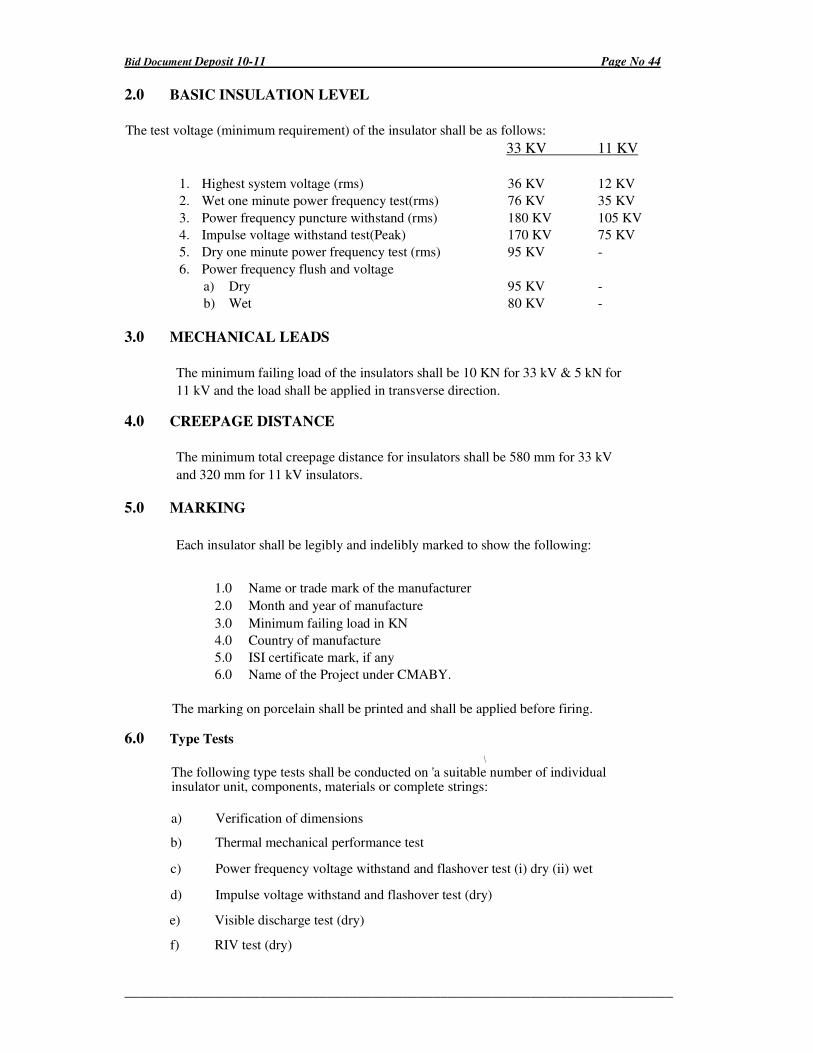
Bid Document Deposit 10-11 Page No 44
_________________________________________________________________________
2.0 BASIC INSULATION LEVEL
The test voltage (minimum requirement) of the insulator shall be as follows:
33 KV 11 KV
1. Highest system voltage (rms) 36 KV 12 KV
2. Wet one minute power frequency test(rms) 76 KV 35 KV
3. Power frequency puncture withstand (rms) 180 KV 105 KV
4. Impulse voltage withstand test(Peak) 170 KV 75 KV
5. Dry one minute power frequency test (rms) 95 KV -
6. Power frequency flush and voltage
a) Dry 95 KV -
b) Wet 80 KV -
3.0 MECHANICAL LEADS
The minimum failing load of the insulators shall be 10 KN for 33 kV & 5 kN for
11 kV and the load shall be applied in transverse direction.
4.0 CREEPAGE DISTANCE
The minimum total creepage distance for insulators shall be 580 mm for 33 kV
and 320 mm for 11 kV insulators.
5.0 MARKING
Each insulator shall be legibly and indelibly marked to show the following:
1.0 Name or trade mark of the manufacturer
2.0 Month and year of manufacture
3.0 Minimum failing load in KN
4.0 Country of manufacture
5.0 ISI certificate mark, if any
6.0 Name of the Project under CMABY.
The marking on porcelain shall be printed and shall be applied before firing.
6.0 Type Tests
\
The following type tests shall be conducted on 'a suitable number of individual insulator unit, components, materials or complete strings:
a) Verification of dimensions
b) Thermal mechanical performance test
c) Power frequency voltage withstand and flashover test (i) dry (ii) wet
d) Impulse voltage withstand and flashover test (dry)
e) Visible discharge test (dry)
f) RIV test (dry)
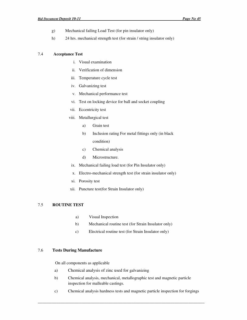
Bid Document Deposit 10-11 Page No 45
_________________________________________________________________________
g) Mechanical failing Load Test (for pin insulator only)
h) 24 hrs. mechanical strength test (for strain / string insulator only)
7.4 Acceptance Test
i. Visual examination
ii. Verification of dimension
iii. Temperature cycle test
iv. Galvanizing test
v. Mechanical performance test
vi. Test on locking device for ball and socket coupling
vii. Eccentricity test
viii. Metallurgical test
a) Grain test
b) Inclusion rating For metal fittings only (in black
condition)
c) Chemical analysis
d) Microstructure.
ix. Mechanical failing load test (for Pin Insulator only)
x. Electro-mechanical strength test (for strain insulator only)
xi. Porosity test
xii. Puncture test(for Strain Insulator only)
7.5 ROUTINE TEST
a) Visual Inspection
b) Mechanical routine test (for Strain Insulator only)
c) Electrical routine test (for Strain Insulator only)
7.6 Tests During Manufacture
On all components as applicable
a) Chemical analysis of zinc used for galvanizing
b) Chemical analysis, mechanical, metallographic test and magnetic particle
inspection for malleable castings.
c) Chemical analysis hardness tests and magnetic particle inspection for forgings
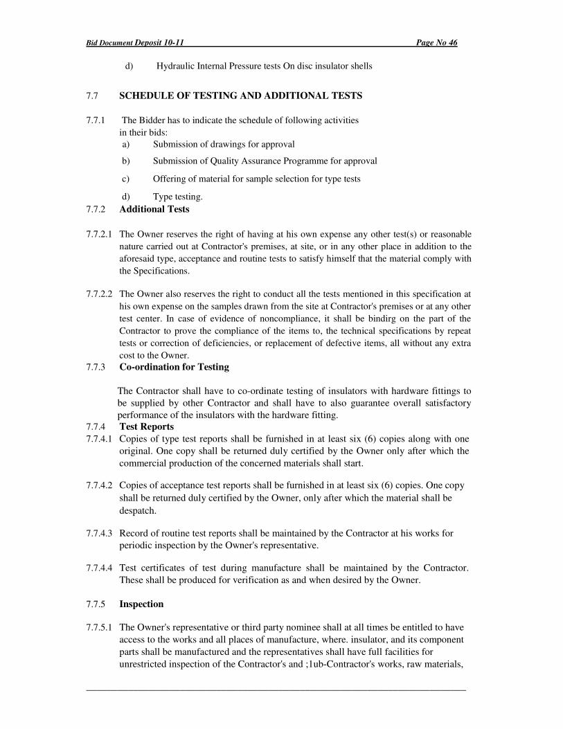
Bid Document Deposit 10-11 Page No 46
_________________________________________________________________________
d) Hydraulic Internal Pressure tests On disc insulator shells
7.7 SCHEDULE OF TESTING AND ADDITIONAL TESTS
7.7.1 The Bidder has to indicate the schedule of following activities
in their bids:
a) Submission of drawings for approval
b) Submission of Quality Assurance Programme for approval
c) Offering of material for sample selection for type tests
d) Type testing.
7.7.2 Additional Tests
7.7.2.1 The Owner reserves the right of having at his own expense any other test(s) or reasonable
nature carried out at Contractor's premises, at site, or in any other place in addition to the
aforesaid type, acceptance and routine tests to satisfy himself that the material comply with
the Specifications.
7.7.2.2 The Owner also reserves the right to conduct all the tests mentioned in this specification at
his own expense on the samples drawn from the site at Contractor's premises or at any other
test center. In case of evidence of noncompliance, it shall be bindirg on the part of the
Contractor to prove the compliance of the items to, the technical specifications by repeat
tests or correction of deficiencies, or replacement of defective items, all without any extra
cost to the Owner.
7.7.3 Co-ordination for Testing
The Contractor shall have to co-ordinate testing of insulators with hardware fittings to
be supplied by other Contractor and shall have to also guarantee overall satisfactory
performance of the insulators with the hardware fitting.
7.7.4 Test Reports
7.7.4.1 Copies of type test reports shall be furnished in at least six (6) copies along with one
original. One copy shall be returned duly certified by the Owner only after which the
commercial production of the concerned materials shall start.
7.7.4.2 Copies of acceptance test reports shall be furnished in at least six (6) copies. One copy
shall be returned duly certified by the Owner, only after which the material shall be
despatch.
7.7.4.3 Record of routine test reports shall be maintained by the Contractor at his works for
periodic inspection by the Owner's representative.
7.7.4.4 Test certificates of test during manufacture shall be maintained by the Contractor.
These shall be produced for verification as and when desired by the Owner.
7.7.5 Inspection
7.7.5.1 The Owner's representative or third party nominee shall at all times be entitled to have
access to the works and all places of manufacture, where. insulator, and its component
parts shall be manufactured and the representatives shall have full facilities for
unrestricted inspection of the Contractor's and ;1ub-Contractor's works, raw materials,
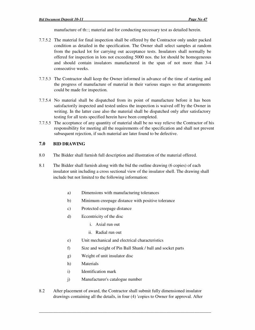
Bid Document Deposit 10-11 Page No 47
_________________________________________________________________________
manufacture of th::; material and for conducting necessary test as detailed herein.
7.7.5.2 The material for final inspection shall be offered by the Contractor only under packed
condition as detailed in the specification. The Owner shall select samples at random
from the packed lot for carrying out acceptance tests. Insulators shall normally be
offered for inspection in lots not exceeding 5000 nos. the lot should be homogeneous
and should contain insulators manufactured in the span of not more than 3-4
consecutive weeks.
7.7.5.3 The Contractor shall keep the Owner informed in advance of the time of starting and
the progress of manufacture of material in their various stages so that arrangements
could be made for inspection.
7.7.5.4 No material shall be dispatched from its point of manufacture before it has been
satisfactorily inspected and tested unless the inspection is waived off by the Owner in
writing. In the latter case also the material shall be dispatched only after satisfactory
testing for all tests specified herein have been completed.
7.7.5.5 The acceptance of any quantity of material shall be no way relieve the Contractor of his
responsibility for meeting all the requirements of the specification and shall not prevent
subsequent rejection, if such material are later found to be defective.
7.0 BID DRAWING
8.0 The Bidder shall furnish full description and illustration of the material offered.
8.1 The Bidder shall furnish along with the bid the outline drawing (6 copies) of each
insulator unit including a cross sectional view of the insulator shell. The drawing shall
include but not limited to the following information:
a) Dimensions with manufacturing tolerances
b) Minimum creepage distance with positive tolerance
c) Protected creepage distance
d) Eccentricity of the disc
i. Axial run out
ii. Radial run out
e) Unit mechanical and electrical characteristics
f) Size and weight of Pin Ball Shank / ball and socket parts
g) Weight of unit insulator disc
h) Materials
i) Identification mark
j) Manufacturer's catalogue number
8.2 After placement of award, the Contractor shall submit fully dimensioned insulator
drawings containing all the details, in four (4) 'copies to Owner for approval. After
Bid Document Deposit 10-11 Page No 48
_________________________________________________________________________
getting approval from Owner and successful completion of all the type tests, the
Contractor shall submit 20 more copies of the same drawing to the Owner for further
distribution and field use at Owner's end.
9.0 Guaranteed Technical Particulars
The guaranteed technical particulars in respect of the Pin Insulators offered shall
be submitted along with the tender.
Bid Document Deposit 10-11 Page No 49
_________________________________________________________________________
5.0 TECHNICAL SPECIFICATION FOR 11 KV DISC. INSULATORS (T&C) 45 KN
1.0 SCOPE
This specification cover the design, manufactures, testing at
manufacturer's works, transport to site, insurance, storage, erection
and commissioning of strain insulators required for 11 KV line.
2.0 STANDARD
Strain insulators Tongue and Clevis type suitable for 11 KV lines shall be
conforming to IS : 731/1971 with its latest amendments and revision and
having mechanical failing load of 45 K.N.
Insulators conforming to any other internationally accepted standards which
ensure equal or higher quality than the standard mentioned would also be
acceptable.
Where the material is offered according to the inter-national accepted
standard a copy of the specification shall be attached with the tender.
2.1 GENERAL REQUIREMENT:
The porcelain should be sound, free from defects, thoroughly verified and
smoothly glazed. Unless otherwise specified, the glaze shall be brown colour.
The glaze shall cover all the porcelain parts of the insulators except these
areas which serve as support during firing or are left unglazed for purpose of .
assembly.
2.2 The design of the insulator shall be such that stress due to expansion and contraction in any part of the insulator shall not lead to deterioration. The porcelain shall not engage directly with hard metal.
2.3 The cement use in the construction of insulator shall not cause fracture by expansion or loosening by contraction and proper care shall be taken to locate the individual parts correctly during commencing. The cement shall not give rise to chemical reaction with metal fitting and its thickness shall be as uniform as possible.
2.4 The insulator shall be multi-petty-coat type.
2.5 The insulator shall be in one piece.
2.6 CLIMATIC CONDITIONS.:
(i) Maximum ambient temperature in shade : 40°C
(ii) Minimum daily average ambient air temperature : 35°C
(iii) Maximum yearly average ambient air temperature : 30°C
Bid Document Deposit 10-11 Page No 50
_________________________________________________________________________
(iv) Maximum ambient temperature : 2°C
(v) Maximum relative humidity : 93%
(vi) Average number of thunder storms days per annum : 45 days
(vii) Average number of rainy days per annum : 150 days
(viii) Average annual rainfall : 2280 mm
(ix) Number of months of tropical monsoon conditions : 5 months
(x) Maximum wind pressure : 150 Kg/sq.m
(xi) Altitude not exceeding : 1000 M
4.0 BASIC INSULATION LEVEL
The test voltage (minimum requirement) of the insulator shall be as follows:
a) Highest system voltage : 12 KV(rms) b) Wet one minute power frequency test : 35 KV(rms) c) Power frequency puncture withstand test : 1.3 times the actual dry
flashover voltage d) Impulse voltage withstand test : 75 KV (rms)
5.0 MECHANICAL LOADS
The minimum failing load of the insulators shall be 45 KN and the load shall be applied
transverse.
6.0 CREEP AGE DISTANCE:
The minimum total creepage distance for insulators shall be suitable for heavily polluted
and humidity atmospheric conditions and shall be 320 mm.
7.0 MARKING
Each insulator shall be legibly and indelibly marked to show the following:
a) Name or trade mark of the manufacturer
b) Month and year of manufacture
c) Minimum failing load in KN
d) Country of manufacture
e) ISI certificate mark and name of the project under "CMABY"
The marking on porcelain shall be printed and shall be applied before suitably.
8.0 TEST
8.1 Type test
The following type tests shall be conducted on a suitable number of individual insulator
unit, components, materials or complete strings:
1.0 Verification of dimensions
Bid Document Deposit 10-11 Page No 51
_________________________________________________________________________
2.0 Thermal mechanical performance test
3.0 Power frequency voltage withstand and flashover test (i) dry (ii) wet
4.0 Impulse voltage withstand and flashover test (dry)
5.0 Visible discharge test (dry)
6.0 RIV test (dry)
7.0 Mechanical failing Load Test (for pin insulator only)
8.0 24 hrs. mechanical strength test (for strain I string insulator only)
8.2 Acceptance Tests
a) Visual examination
b) Verification of dimensions
c) Temperature cycle test
d) Galvanizing test
e) Mechanical performance test
f) Test on locking device for ball and socket coupling
g) Eccentricity test
h) Metallurgical test
(i) Grain size
(ii) Inclusion rating
(iii) Chemical analysis
(iv) Microstructure
i) Mechanical failing load test (for Pjn Insulator only)
j) Electro-mechanical strength test (for Strain insulator only)
k) Porosity test
l) Puncture test (for strain Insulator only)
8.3 Routine Tests
a. Visual Inspection
b. Mechanical routine test for Strain Insulator only)
c. Electrical routine test (for Strain Insulator only)
7.4 Tests During Manufacture
On all components as applicable
a) Chemical analysis of zinc used for galvanizing
b) Chemical analysis, mechanical, metallographic test and magnetic particle inspection for
malleable castings.
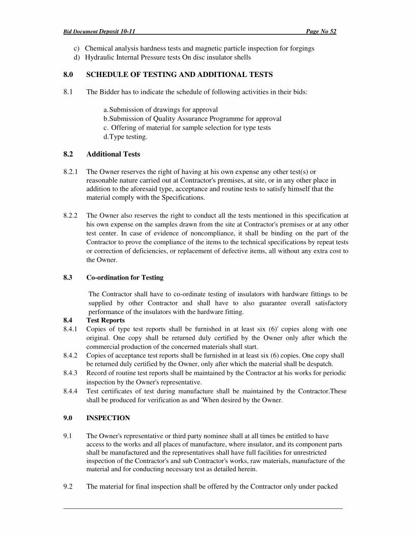
Bid Document Deposit 10-11 Page No 52
_________________________________________________________________________
c) Chemical analysis hardness tests and magnetic particle inspection for forgings
d) Hydraulic Internal Pressure tests On disc insulator shells
8.0 SCHEDULE OF TESTING AND ADDITIONAL TESTS
8.1 The Bidder has to indicate the schedule of following activities in their bids:
a. Submission of drawings for approval
b. Submission of Quality Assurance Programme for approval
c. Offering of material for sample selection for type tests
d. Type testing.
8.2 Additional Tests
8.2.1 The Owner reserves the right of having at his own expense any other test(s) or
reasonable nature carried out at Contractor's premises, at site, or in any other place in
addition to the aforesaid type, acceptance and routine tests to satisfy himself that the
material comply with the Specifications.
8.2.2 The Owner also reserves the right to conduct all the tests mentioned in this specification at
his own expense on the samples drawn from the site at Contractor's premises or at any other
test center. In case of evidence of noncompliance, it shall be binding on the part of the
Contractor to prove the compliance of the items to the technical specifications by repeat tests
or correction of deficiencies, or replacement of defective items, all without any extra cost to
the Owner.
8.3 Co-ordination for Testing
The Contractor shall have to co-ordinate testing of insulators with hardware fittings to be
supplied by other Contractor and shall have to also guarantee overall satisfactory
performance of the insulators with the hardware fitting.
8.4 Test Reports
8.4.1 Copies of type test reports shall be furnished in at least six (6)' copies along with one
original. One copy shall be returned duly certified by the Owner only after which the
commercial production of the concerned materials shall start.
8.4.2 Copies of acceptance test reports shall be furnished in at least six (6) copies. One copy shall
be returned duly certified by the Owner, only after which the material shall be despatch.
8.4.3 Record of routine test reports shall be maintained by the Contractor at his works for periodic
inspection by the Owner's representative.
8.4.4 Test certificates of test during manufacture shall be maintained by the Contractor.These
shall be produced for verification as and 'When desired by the Owner.
9.0 INSPECTION
9.1 The Owner's representative or third party nominee shall at all times be entitled to have
access to the works and all places of manufacture, where insulator, and its component parts
shall be manufactured and the representatives shall have full facilities for unrestricted
inspection of the Contractor's and sub Contractor's works, raw materials, manufacture of the
material and for conducting necessary test as detailed herein.
9.2 The material for final inspection shall be offered by the Contractor only under packed
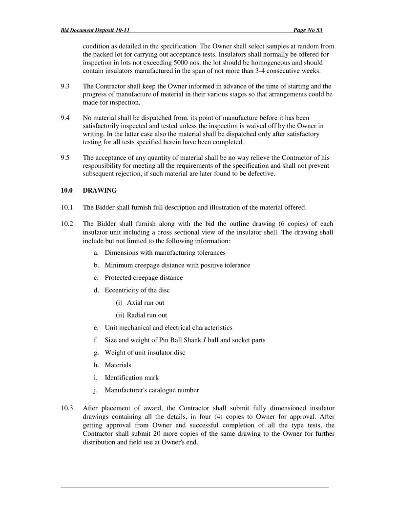
Bid Document Deposit 10-11 Page No 53
_________________________________________________________________________
condition as detailed in the specification. The Owner shall select samples at random from
the packed lot for carrying out acceptance tests. Insulators shall normally be offered for
inspection in lots not exceeding 5000 nos. the lot should be homogeneous and should
contain insulators manufactured in the span of not more than 3-4 consecutive weeks.
9.3 The Contractor shall keep the Owner informed in advance of the time of starting and the
progress of manufacture of material in their various stages so that arrangements could be
made for inspection.
9.4 No material shall be dispatched from. its point of manufacture before it has been
satisfactorily inspected and tested unless the inspection is waived off by the Owner in
writing. In the latter case also the material shall be dispatched only after satisfactory
testing for all tests specified herein have been completed.
9.5 The acceptance of any quantity of material shall be no way relieve the Contractor of his responsibility for meeting all the requirements of the specification and shall not prevent subsequent rejection, if such material are later found to be defective.
10.0 DRAWING
10.1 The Bidder shall furnish full description and illustration of the material offered.
10.2 The Bidder shall furnish along with the bid the outline drawing (6 copies) of each
insulator unit including a cross sectional view of the insulator shell. The drawing shall
include but not limited to the following information:
a. Dimensions with manufacturing tolerances
b. Minimum creepage distance with positive tolerance
c. Protected creepage distance
d. Eccentricity of the disc
(i) Axial run out
(ii) Radial run out
e. Unit mechanical and electrical characteristics
f. Size and weight of Pin Ball Shank I ball and socket parts
g. Weight of unit insulator disc
h. Materials
i. Identification mark
j. Manufacturer's catalogue number
10.3 After placement of award, the Contractor shall submit fully dimensioned insulator
drawings containing all the details, in four (4) copies to Owner for approval. After
getting approval from Owner and successful completion of all the type tests, the
Contractor shall submit 20 more copies of the same drawing to the Owner for further
distribution and field use at Owner's end.
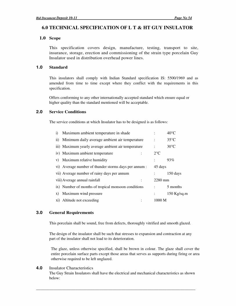
Bid Document Deposit 10-11 Page No 54
_________________________________________________________________________
6.0 TECHNICAL SPECIFICATION OF L T & HT GUY INSULATOR
1.0 Scope
This specification covers design, manufacture, testing, transport to site,
insurance, storage, erection and commissioning of the strain type porcelain Guy
Insulator used in distribution overhead power lines.
1.0 Standard
This insulators shall comply with Indian Standard specification IS: 5500/1969 and as
amended from time to time except where they conflict with the requirements in this
specification.
Offers conforming to any other internationally accepted standard which ensure equal or
higher quality than the standard mentioned will be acceptable.
2.0 Service Conditions
The service conditions at which Insulator has to be designed is as follows:
i) Maximum ambient temperature in shade : 40°C
ii) Minimum daily average ambient air temperature : 35°C
iii) Maximum yearly average ambient air temperature : 30°C
iv) Maximum ambient temperature : 2°C
v) Maximum relative humidity : 93%
vi) Average number of thunder storms days per annum : 45 days
vii) Average number of rainy days per annum : 150 days
viii) Average annual rainfall : 2280 mm
ix) Number of months of tropical monsoon conditions : 5 months
x) Maximum wind pressure : 150 Kg/sq.m
xi) Altitude not exceeding : 1000 M
3.0 General Requirements
This porcelain shall be sound, free from defects, thoroughly vitrified and smooth glazed.
The design of the insulator shall be such that stresses to expansion and contraction at any
part of the insulator shall not load to its deterioration.
The glaze, unless otherwise specified, shall be brown in colour. The glaze shall cover the
entire porcelain surface parts except those areas that serves as supports during firing or area
otherwise required to be left unglazed.
4.0 Insulator Characteristics
The Guy Strain Insulators shall have the electrical and mechanical characteristics as shown
below:
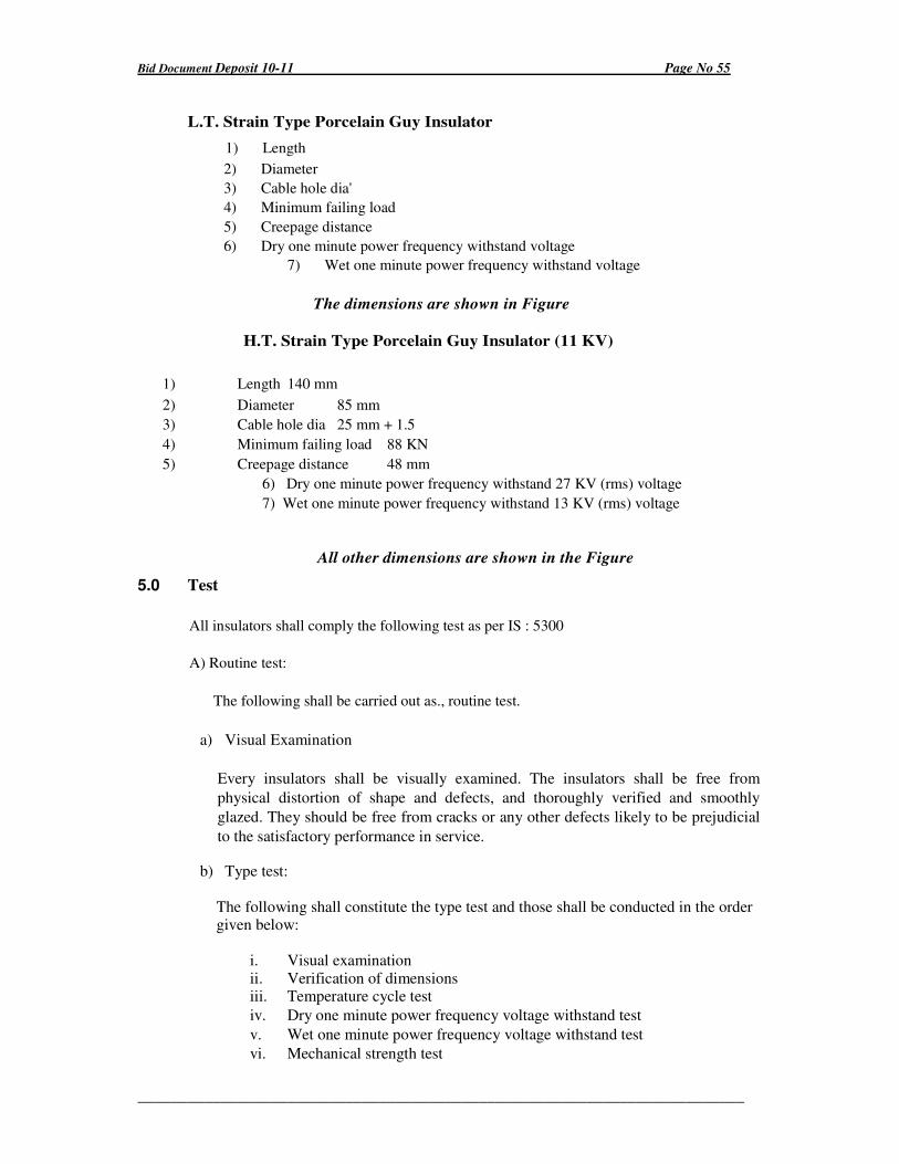
Bid Document Deposit 10-11 Page No 55
_________________________________________________________________________
L.T. Strain Type Porcelain Guy Insulator
1) Length
2) Diameter
3) Cable hole dia'
4) Minimum failing load
5) Creepage distance
6) Dry one minute power frequency withstand voltage
7) Wet one minute power frequency withstand voltage
The dimensions are shown in Figure
H.T. Strain Type Porcelain Guy Insulator (11 KV)
1) Length 140 mm
2) Diameter 85 mm
3) Cable hole dia 25 mm + 1.5
4) Minimum failing load 88 KN
5) Creepage distance 48 mm
6) Dry one minute power frequency withstand 27 KV (rms) voltage
7) Wet one minute power frequency withstand 13 KV (rms) voltage
All other dimensions are shown in the Figure
5.0 Test
All insulators shall comply the following test as per IS : 5300
A) Routine test:
The following shall be carried out as., routine test.
a) Visual Examination
Every insulators shall be visually examined. The insulators shall be free from
physical distortion of shape and defects, and thoroughly verified and smoothly
glazed. They should be free from cracks or any other defects likely to be prejudicial
to the satisfactory performance in service.
b) Type test:
The following shall constitute the type test and those shall be conducted in the order given below:
i. Visual examination ii. Verification of dimensions iii. Temperature cycle test
iv. Dry one minute power frequency voltage withstand test
v. Wet one minute power frequency voltage withstand test
vi. Mechanical strength test
Bid Document Deposit 10-11 Page No 56
_________________________________________________________________________
vii. Porosity test.
The number of samples for type test are to be agreed to between the purchaser and the supplier.
c) Acceptance Test (to be conducted in the following order)
i. Verification of Dimensions ii. Temperature cycle test iii. Mechanical strength test iv. Porosity test
The number of samples for acceptance test shall be in accordance to IS: 5300.
d) Type test certificate fro National Test House/ Govt. recognized institutions/
Govt. recognized public Testing Laboratories are also to be submitted along with
the offer, failing which the offer is liable for rejection.
6.0 Marking
Each insulator shall be legibly and indelibly marked to shown the following:
a. Name of trade mark of the manufacturer b. Year of manufacture and name of project ABY
Marking on porcelain shall be printed and shall be applied before firing. Insulators may also be marked with the ISI certification mark.
7.0 Inspection
All tests and inspections shall be carried out at the place of manufacturer unless
otherwise agreed by the purchaser and the manufacturer at the time of purchase. The
manufacturer shall afford the inspector representing the purchaser or the third party
nominee, all reasonable facilities, without charge, to satisfy that materials are being
furnished in accordance with the specification. The purchaser reserves the right to have
the test carried out at his own cost by an independent agency whenever there is dispute
regarding the quality of materials supplied.
8.0 Drawing
Drawing specifically showing all dimensions is to be submitted along with technical bid.
Bid Document Deposit 10-11 Page No 57
_________________________________________________________________________
7.0 TECHNICAL SPECIFICATION FOR STAY SET (HT & LT)
1.0 Scope:
This specification covers the design, manufacture testing at manufacturer's works,
transport to site, insurance, storage, erection and commissioning of the Stay Sets (L
T/HT) required from the distribution lines at designated locations.
2.0 Standard: All the materials of stay sets shall comply in all respects with the
requirements of the latest edition of the relevant Indian or British Standard
specification except in so far as they are modified this specification.
3.0 Design Consideration: Stay Rods shall be Galvanised and shall be of circular Cross-section with
bow, thimble, nuts and bolts. The Rods shall be threaded at one end up to a minimum of 30 cm
length and shall be complete with Galvanised M.S. Anchor Plates with all necessary accessories.
All parts shall be heavily galvanised.
4.0 Climatic Conditions
(i) Maximum ambient temperature in shade : 40°C
(ii) Minimum daily average ambient air temperature : 35°C
(iii) Maximum yearly average ambient air temperature : 30°C
(iv) Maximum ambient temperature : 2°C
(v) Maximum relative humidity : 93%
(vi) Average number of thunder storms days per annum : 45 days
(vii) Average number of rainy days per annum : 150 days
(viii) Average annual rainfall : 2280 mm
(ix) Number of months of tropical monsoon conditions : 5 months
(x) Maximum wind pressure : 150 Kg/sq.m
(xi) Altitude not exceeding : 1000 M
5.0 Testing: Type and Routine Tests should be carried on different components of each stay sets as
per relevant Indian Standard specification and certified copies of the above should be submitted
along with the tender.
6.0 Schedule Requirement·: Stay sets complete with Thimble bow stay
Rod/Anchor plate with nuts etc. and made of Rolled mild Steel Rod and plates as per
detailed given below:
A) Anchor Plate:
II) Thickness not below 5 mm.
III) Size not below 230 mmX230 mm with smooth edges (for L T)
IV) Size not below 300 mmX300 mm with smooth edges (for HT)
V) Well galvanised
Bid Document Deposit 10-11 Page No 58
_________________________________________________________________________
VI) Materials M.S. Rolled plate
VII) About 20 mm square hole at centre for locking the plate with the Anchor Rod
(for HT) & 19 mm (for L T)
B) Anchor Rod:
2.1 Length 1800 mm or above
2.2 Threaded length 30 cm or above
2.3 Diameter 18 mm or above (for HT)
2.4 Anchor plate and head: square size 30mm X 30mm with thickness 25 mm
having matching square size shank for locking the Anchor plate.
2.5 One ratched lock nuts, grooves must match the grooves at bow flange
2.6 One check nut.
2.7 Materials H.S.
2.8 Component well galvanised with extra care for the threaded portion.
2.9 Both lock and check nuts should be matching to the Anchor Rod thread such
that punching of thread after assembly at site safeguards them against
removal.
C) Thimble: The match bow diameter and bend should be well galvanised.
D) Bow: Rod diameter 12mm/16mm or above overall length 35cm/40cm or above. Flange
with well formed locking grooves matching the locking nut, bow ends will be riveted
securely with the flange. All items to be galvanised.
7.0 Inspection: All tests and inspections shall be carried out at the place of
manufacturer unless otherwise agreed by the purchaser and the manufacturers at
the time of purchase. A manufacturer shall afford the inspector representing the
purchaser or third party nominee, all reasonable facilities, without charge to satisfy
that the materials are being purchased as per specification. The purchaser reserves
the right to have the test carried out at his cost by an independent agency,
whenever there is dispute regarding the quality of the materials supplied.
Bid Document Deposit 10-11 Page No 59
_________________________________________________________________________
8.0 TECHNICAL SPECIFICATION FOR G.I. STAY WIRE
1.0 Scope
The specification covers design, manufacturing and testing, transporting to site,
insurance, storage, erection and commissioning of G.I. Stay Wire 7/10SWG and
7/14SWG.
2.0 Materials.
The wire shall be manufactured from steel, made by any suitable process and shall not contain
sulphur and phosphorus exceeding 0.065 percent each.
The wires shall be coated with Zinc Grade Zn 98 of IS:209-1966
The general requirements for the supply of Galvanized stay strand shall be in accordance with
IS:1387-1967
3.0 Construction
3.1 Grades: The wire shall be of Grade-I and tensile strength range 45 up to and including Kg/mm
3.2 The Galvanized stay strand shall be of 7/2 mm and 7/3.15 mm. the lay of the strands shall be
of the length of 7/2 mm and Tables-I of IS: 2141-1963. the wires shall be so stranded
together that when and evenly distributed pull is applied at the end of the completed strand
each wire will take equal share of the pull.
3.3 The length of the strand which may be supplied without joints in the individual wires
comprising it, depend on the length of wire which may be carried by the bobbin in a normal
stranding machine. The normal lengths of strand which shall be supplied without joints in
the individual wires, excluding welds made in the rod before drawing shall be as given
below. The lengths may be exceeded by agreement between the manufacturer and the
purchaser.
Diameter of wire in strand Normal length without joints of weld
3.15 mm 1000 M
2.0 mm 3000 M
3.4 In cases where joints are permitted, they shall be made by welding of brazing joints in the
same wire shall be separated by a length of not less than that shown in 3.3 and joints in
different wires in a strand shall not be less than 20 M apart.
4.0 Freedom from Defects :
4.1 Each coil shall be warranted to contain no weld joint or splice other than in the rod before it
is drawn and those permitted in 3.4. The wire shall be circular and shall be free scale,
irregularities imperfections flaws splits and other defects. The Zinc coating shall be smooth,
even the bright.
Bid Document Deposit 10-11 Page No 60
_________________________________________________________________________
5.0 Tests:
5.1 Chemical Analysis: Unless otherwise agreed to between the purchaser and the supplier, the
chemical analysis be carried out.
5.2 Tensile Test: The wire when tested in accordance with IS: 1521-1960, on gauge length of
100 mm shall have the minimum tensile strength specified in Tables 1 of IS : 2141/1968
according to the grade of the wire.
5.2.1 The tensile strength of the finalised strand shall be not less tI~an 93 percent of the aggregate
of the single wires.
5.3 Delivery test: The wire shall be subjected to the wrapping test in accordance with IS :
1755/1961. When wrapped eight times round its own diameter and on being subsequently
strengthened the wire shall not break or split.
5.3.1 Coating test: The uniformity of Zinc coating shall be tested by the method specified in IS :
2633/1964. The wire shall withstand the number or dips as specified in IS : 4826-1968.
6.0 Marking:
6.1 Each coil shall be provided with a label, fixed firmly on the inneJ part of the coil, bearing
'the following information.
a. Manufacturer's name or trade mark
b. Lot number and coil number
c. A brief description and quality of the materials.
d. Weight and
e. Any other particulars specified by the purchaser
.
6.2 The label may also be marked with the ISI certification mark.
7.0 Inspection: The test should be carried out in presence of the inspecting officer deputed by
purchaser or third party nominee and the test should be in conformity with relevant IS .
Bid Document Deposit 10-11 Page No 61
_________________________________________________________________________
9.0 TECHNICAL SPECIFICATION FOR CROSS ARM
1.0 Scope
This covers manufacturing, transport to site, insurance, storage, erection and
commissioning of different types of Cross Arms suitable for 33 kV, 11 kV and L T lines.
2.0 Climatic Conditions
The cross arms should be suitable for the climatic condition mentioned below:
a) Maximum temperature of air in shade 40°C
b) Minimum temperature of air in shade 2°C
c) Maximum temperature of air in Sun 40°C
d) Maximum Humidity 93%
e) Average number of thunderstorm days 45
f) Average numbers of dust storms per annum 10
g) Maximum rainfall/annum 3500 mm
h) Average rainfall 2280 mm
i) Wind Pressure 97.8 Kg/Sq.mm
j) Altitude above MSL 100 m to 1000 m
3.0 Standards
A. Cross Arm for 33 KV Lines.
• The Cross Arms shall be made as per the drawings.
• The Cross Arms shall be made out of 100 X 50x6mm MS Channel
and MS Flat 75 X 8 mm
• The Cross Arm shall be hot dipped galvanized generally conforming
to the IS-2633/1972
• The Clamps for the Cross Arms shall be made out of 75 X 8 mm MS
Flat and shall be hot dipped galvanized conforming to IS-2633/1972
• The Clamps shall be designed to fit for STP/PSC Poles.
• The rolling and cutting tolerance for steel products conforming to
IS-226 shall be those specified in IS-1852/1972 or latest version.
B. Horizontal Type Cross Arm for 11 KV / 33 KV
Bid Document Deposit 10-11 Page No 62
_________________________________________________________________________
• It shall comprise of 100 X 50x6 mm, 3.2 M long MS Channel for 33
KV and 2.2 mt. long for 11 KV to be provided on STP/ PSCC Poles
• The rolling and cutting tolerance for steel products conforming to
IS-226 shall be those specified in IS-1852/1972 or latest version.
• The Cross Arm shall be hot dipped galvanized generally conforming
to the IS-2633/1972
• The clamps for the Cross Arms shall be made of 50 X 6 MS Flat and
shall be hot dipped galvanized.
• The Cross Arm should not have any welded joints.
4.0 INSPECTION
Inspection may be carried out by the purchaser or third party nominee at any stage of
manufacture. The supplier shall grant free access to the purchaser's representative or
third party nominee at a reasonable time when the work is in progress. Inspection and
acceptance of any equipment under this specification by the purchaser shall not
relieve the supplier of his obligation of furnishing equipment in accordance with the
specification and shall not prevent subsequent rejection if the equipment is found
defective.
Bid Document Deposit 10-11 Page No 63
_________________________________________________________________________
10.0 TECHNICAL SPECIFICATION FOR G.I. WIRE
1.0 Scope
This specification covers the manufacturing, testing at works, transport to site,
insurance, storage, erection and commissioning of Galvanised Iron Wire of sizes 4
mm and 5 mm diameter.
2.0 General requirements
2.1 It relating to the supply of mild steel wire shall be as per IS: 1387/1967 and the wire shall be drawn from the wire rods conforming to IS: 7887/1975.
2.2 The requirements for chemical composition for the wires shall conform to
IS:7887/1975.
2.3 Mild steel wire for General Engineering purpose shall be of following sizes:
I) 4mm - diameter (8 SWG)
II) 5mm - diameter (6 SWG)
2.4 Tolerance permitted on the diameter of wire shall be as per Table -1 of IS:280/1978.
3.0 Climatic Conditions
The cross arms should be suitable for the climatic condition mentioned In these
bidding documents:
4.0 Mechanical Properties
2.10 Tensile Test: Tensile strength of wire when tested in accordance with IS:
1521-1972, shall be within the limits given in Table-2 of IS: 280/1978.
2.11 Wrapping Test: Wires shall be subjected wrapping test in accordance with IS:
1755-1961. The wire shall withstand without breaking or splitting. being wrapped eight
times round its own diameter and subsequently straightened.
5.0 Surface finish
5.1 The wire shall have galvanized finishes. The galvanized coating of steel wire shall conform
to the requirements for anyone of the types of coatings given in IS: 4826-1968 as per
agreement with the purchaser.
5.2 The coating test for finishes other than galvanized, copper coated or tinned shall be subject
to between the purchaser and the manufacturer.
5.3 Unless otherwise agreed to the method of drawing representative samples of the material
and the criteria for conforming shall be as prescribed in Appendix (A) of IS: 280/1978.
5.4 All finished wires shall be well and cleanly drawn to the dimensions specified. The wire shall be sound, free from splits, surface flaws, rough jagged and imperfect edges and other
Bid Document Deposit 10-11 Page No 64
_________________________________________________________________________
harmful surface defects.
5.5 Each coil of wire shall be suitably bound and fastened compactly and shall be protected by
suitably wrapped.
6.0 INSPECTION
Inspection may be carried out by the purchaser or third party nominee at any
stage of manufacture. The supplier shall grant free access to the purchaser's
representative or third party nominee at a reasonable time when the work is in
progress. Inspection and acceptance of any equipment under this specification
by the purchaser shall not relieve the supplier of his obligation of furnishing
equipment in accordance with the specification and shall not prevent
subsequent rejection if the equipment is found defective.
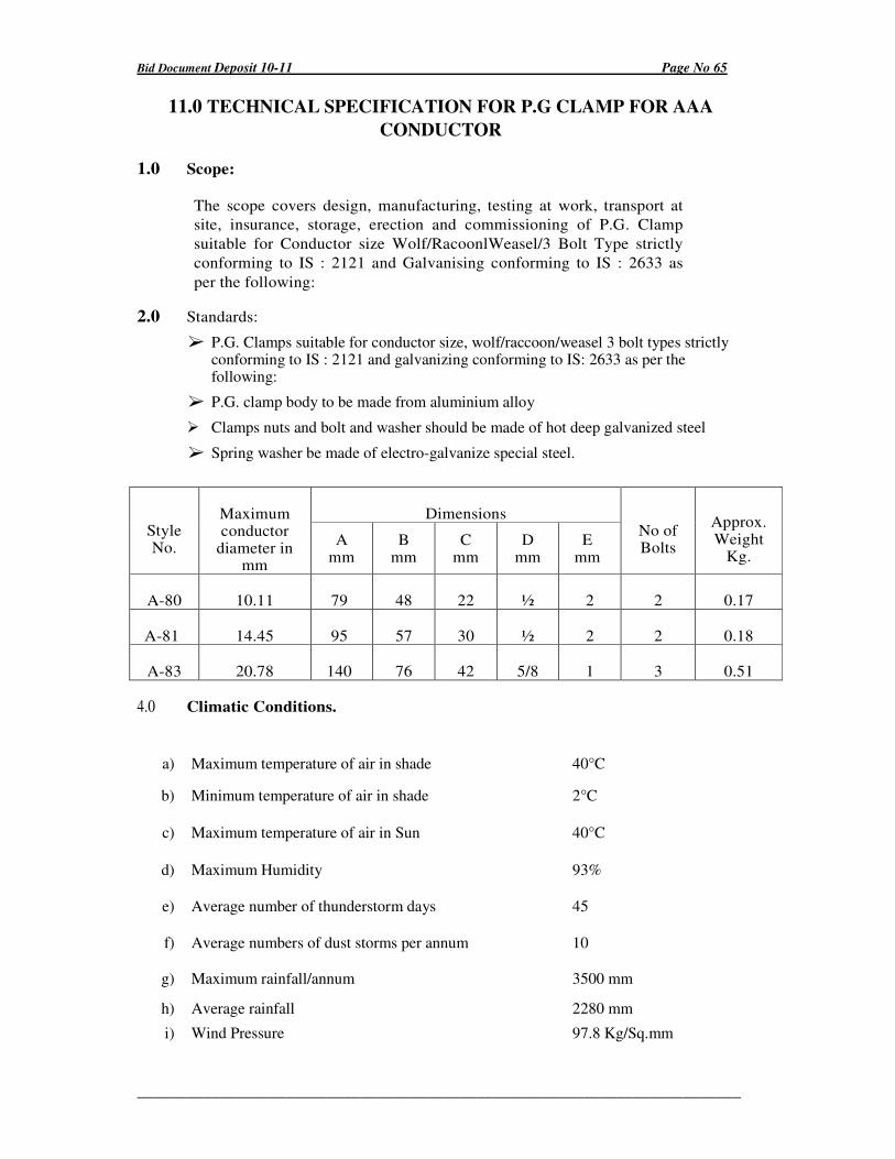
Bid Document Deposit 10-11 Page No 65
_________________________________________________________________________
11.0 TECHNICAL SPECIFICATION FOR P.G CLAMP FOR AAA
CONDUCTOR
1.0 Scope:
The scope covers design, manufacturing, testing at work, transport at
site, insurance, storage, erection and commissioning of P.G. Clamp
suitable for Conductor size Wolf/RacoonlWeasel/3 Bolt Type strictly
conforming to IS : 2121 and Galvanising conforming to IS : 2633 as
per the following:
2.0 Standards:
� P.G. Clamps suitable for conductor size, wolf/raccoon/weasel 3 bolt types strictly conforming to IS : 2121 and galvanizing conforming to IS: 2633 as per the following:
� P.G. clamp body to be made from aluminium alloy
� Clamps nuts and bolt and washer should be made of hot deep galvanized steel
� Spring washer be made of electro-galvanize special steel.
Dimensions Style No.
Maximum conductor
diameter in mm
A mm
B mm
C mm
D mm
E mm
No of Bolts
Approx. Weight
Kg.
A-80 10.11 79 48 22 ½ 2 2 0.17
A-81 14.45 95 57 30 ½ 2 2 0.18
A-83 20.78 140 76 42 5/8 1 3 0.51
4.0 Climatic Conditions.
a) Maximum temperature of air in shade 40°C
b) Minimum temperature of air in shade 2°C
c) Maximum temperature of air in Sun 40°C
d) Maximum Humidity 93%
e) Average number of thunderstorm days 45
f) Average numbers of dust storms per annum 10
g) Maximum rainfall/annum 3500 mm
h) Average rainfall 2280 mm
i) Wind Pressure 97.8 Kg/Sq.mm
Bid Document Deposit 10-11 Page No 66
_________________________________________________________________________
j) Altitude above MSL 100 m to 1000 m
5.0 INSPECTION
Inspection may be carried out by the purchaser or third party nominee at any stage of
manufacture. The supplier shall grant free access to the purchaser's representative or
third party nominee at a reasonable time when the work is in progress. Inspection and
acceptance of any equipment under this specification by the purchaser shall not relieve
the supplier of his obligation of furnishing equipment in accordance with the
specification and shall not prevent subsequent rejection if the equipment is found
defective.
Bid Document Deposit 10-11 Page No 67
_________________________________________________________________________
12.0 TECHNICAL SPECIFICATION FOR 33 KV A.B. GANG OPERATED
SWITCHES
1.0 Scope:
This specification covers the design, manufacture and testing at works, transport to site,
insurance, storage, erection and commissioning of outdoor type A.C. Gang Operated Air
Break Switches suitable for use on 11 KV power systems conforming to 155: 1818/1972
with up to-date amendments and revisions.
2.0 i) Ratings: 33 KV 400 Amps 50 C/S AC, 3-Phase continuous
ii) Type: The insulators should be of tilting type for 11 KV class and should be suitable for both horizontal and vertical mounting.
iii) Insulators: There will be 3(three) insulators stacks per pole. The insulators
should be manufactured strictly conforming to ISS: 731 1971 with its up to date
amendments and revisions and it should be easily replaceable in the event of any
damage or defect.
The insulator /insulators/stacks and fixture should be procured from reputed insulator manufacturers as integral union and should bear the manufacturers monogram both on the insulators as well as on the malleable caps. A certificate should be furnished to the effect that the insulators along with the fixtures are procured as integral units from the manufacturers. The fixtures are to be of malleable casting wherever applicable .
iv) Main Contacts : The insulators should be complete with :nale contuc~ blades
and self aligning full-floating jaw type female contacts aided with powerful
springs to provide sufficient contact pressure on both sides of the male contact.
The contact surface should be made of non-ferrous alloy such as bronze, gun-
metal of brass. The name of the alloy should be mentioned clearly. Full floating
type contacts shall be preferred. The contacts shall be designed so as to
withstand the rated currents without over-heating and should also be able to
withstand electromagnetic stresses and shattering of rated short time current.
The contact should also assure a good wiping action during engagement and dirt
accumulation.
v) Arching Contacts : The insulators should be provided with securely placed and
replaceable type arching contacts to act as the first and the last contacts to
prevent burning of the main contacts. The moving arching contact arm should be
of adequate section to withstand the arching, should be of sufficient mechanical
strength and should be placed preferably on the top of the main male contact.
vi) Current Carrying Path: All current carrying paths should be of non- ferrous Metals. In case of tilting type of design the flexible cords are to be of honey comb design and should be made of suitable non-ferrous metal. The terminals of the cord should be of the same width as that of the cord itself and be fixed with non-ferrous nuts and bolts. While designing individual areas of all current carrying paths made of nonferrous alloy, prime consideration of mechanical loading and electrical copper equivalent of 1 Amp! sq.mm. loading should be considered.
vii) Terminal Connectors : The insulators should be provided with detachable 6 (six)
Bid Document Deposit 10-11 Page No 68
_________________________________________________________________________
bolted palm type terminal connectors 100 mm long suitably grooved to
accommodate conductors up to 12.5 mm diameter. The connector including the
fixing bolts and nuts should be made of suitable non-ferrous metals such as
brass, bronze and gun-metal which should be clearly indicated.
The six bolted palm type connector-groove portion should be finely grinded and
finished to accommodate aluminium conductor up to 12.5 mm diameter
suitably.
It may be noted that all nonferrous parts should be tinned properly as per best
engineering practice.
A pair of brass plate washer must be provided on each nuts & bolts of the
connector.
viii) Operating Mechanism: The isolators should be assembled on M.S. Galvanised
channel base with holes suitable for fixing on the mounting structures and
should be complete with the follows:
For 11 kV Class Tiltinq Type Desiqn :
Phase coupling shaft: 2 .5 cm x 2.5 cm C.I. solid bar of 2.30 meter length.
Operating Pipe: 2.6 cm outside dia 3.25 mm thick 6 meters long.
The operating mechanism should be complete with intermediate guides suitable
operating handle with padlock and chain for locking the handle in both 'ON' &
'OFF' positions.
The flexible coupling, in case of tilting type design will be supported on hinged
linked made of suitable pairs of G I straps with suitable space to accommodate
the cord and with three hinges. two on the insulator fixtures and one between the
line.
The pivots of the hinges shall be of G.1. nuts and bolts with sufficiently strong split pin arrangements of suitable metal. Suitable spring stop mechanism shall be provided at the base the moving post insulator/post insulators stacks of each pole to prevent overshooting and ensure that the contact surface area held in contact uniformly during closed position and also to held it in position after opening.
Necessary and adequate adjustments should be provided in the operating
mechanism to ensure, synchronous closing and opening in the three phase of
the insulator.
Inter locking should be provided so that earthing switch cannot be operated without first isolating the line. The inter-locking shall be mechanical either through lever arrangements or through locking arrangements or both. Extra for each may be indicated separately. Auxiliary contacts enclosed in a terminal board shall be provided for semaphore indications of open and closed positions of the main isolator as well as open and closed positions of the, earthing contacts.
General considerations: All ferrous parts used in the Isolator units should be
Bid Document Deposit 10-11 Page No 69
_________________________________________________________________________
hO,t .. dip galvanised in accordance with the relevant ISS.
3.0 TEST.
The offers shall invariably be supported by complete type test certificate
from National Test House/C.P. R.I/any other recognised 'Public
Institutions and as per ISS: 9920 (pt-1 to iv) with up to date amendments.
Test certificate should be furnished against individual component parts of
the isolator such as insulators etc. The manufacturers should have the
facilities of laboratory testing of the isolators at their works as per relevant
ISS/ BSS. They should furnish the detailed specifications along with the
make and capacity of testing equipments at their disposal along with
tender.
4.0 Sample
The tenderer shall submit the sample complete with accessories at his own cost along with the tender. Samples not received within the stipulated time may· disqualify the tender. The tender without sample may be rejected outright.
5.0 Climatic Conditions:
a) Maximum temperature of air in shade 40°C
b) Minimum temperature of air in shade 2°C
c) Maximum temperature of air in Sun 40°C
d) Maximum Humidity 93%
e) Average number of thunderstorm days 45
f) Average numbers of dust storms per annum 10
g) Maximum rainfall/annum 3500 mm
h) Average rainfall 2280 mm
i) Wind Pressure 97.8 Kg/Sq.mm
j) Altitude above MSL 100 m to 1000 m
6.0 Inspection
The man-ufacturer shall afford the inspection representing the purchaser or third party
nominee at works all facilities to satisfy him that the material is being furnished in
accordance with specification.
Bid Document Deposit 10-11 Page No 70
_________________________________________________________________________
7.0 Name Plate
The bidder has to provide the following particulars on the name plate of the equipment:
a. Name of the equipment
b. Manufacture's name
c. Operating range
d. Name of the purchaser
7.0 Performance:
The materials should be guaranteed for satisfactory performance for a period of 18
months from the date of receipt of the same in. good conditions or 12 months from the
date of commissioning which ever is earlier and will be subject for free
replacement/repair against any manufacturing defects.