Embed Size (px)
Citation preview

i., I': I; r I
5-770
:!I" .... \.; '- "
.,~ .
5-1 0
5-601
5-676
Assemble Nut Against Bearing As Shown
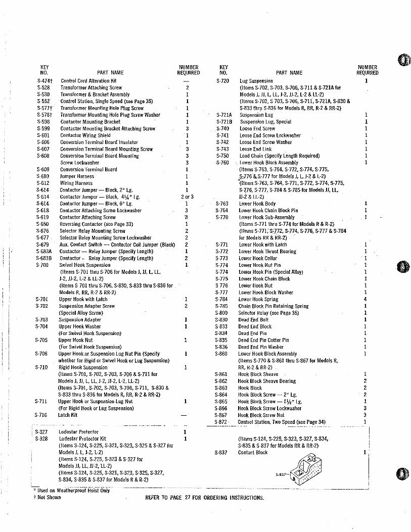
S-700 COMPLETE SWIVEL HOOK SUSPENSION
S-71O COMPLETE RIGID HOOK SUSPENSION
S-720 COMPLETE LUG SUSPEI
. fj/'~ P'" W ,., If
~,,~ ilfJrI_,,,, ~e;~_~ ~ ~J / E§) 5-711
'-~/] ~ "V5•7C
ii§J~ijii! 5-703,
f!£> ." iiii" ADAPTER FOR MODELS .. ,.' ."'" R RR, R-2 & RR-2 . '@-5-704 SHOWN
~ ____ 5-705
/J~~5-706
5-115
5-743 ~-~"""""5-740 ~/(~\"5-741
/ I 5-742 ___ 5-112
~~\"" ~ , , I I , I I
~~-" 5-750: 5-834 \. -" '5-835 ~
\.' , "5-836 ~ I
~ ~33 5-117
-~. I II --- ~ 'I' .-~_,.r __ ~ ~;::::: i 5-119 .-~~, ... ~ 5764 &j t)y5-775 ~ ~ - 0 5-764
6;? /5-776 ;)p 0 5-776
5-774 @ ~
5-776 (®) 5-772/~
~ ~ 5-863
5_784~
5-862
5-777"@
MODELS RR & RR-2 MODEL R & R-2
S-860 LY COMPLETE LOW~R. HOOK BLOCK ASSEMB
.p:> ~/ 5-772 <: W 5-772
I 5-774 5-777 5-774 ~
~)5-784 ~ ~ /5-777
rtP~
MODElS J & L, J-2 & L-2
S-760
5-327~
5-328 LODESTAR
PROTECTOR 'KIT
~5_771 P"\!; COMPLETE LOWER HOOK BLOCK ASSEMBLY
MODELS JJ & LL, JJ-2 & LL-2
S-760 COMPLETE LOWER HOOK BLOCK ASSEMBLY

KEY NO.
S·lOl* S·102* S·106 S·107 S·108 S·109 S·109* S·110 S·111 S·112 S·I13 S·114 S·115 S,116 S·117 S·118 S·119 S·120 S·122 S·124 S·125 S·128 S-129 S-130 S-131 S-131* S-132 S-196 S-197 S-198 S-199 S·200 S-201 S·203 S-205 S-207 S-212 S-213 S-214 S-215 S-216 S-217 S-219 S-220
S-221 S·222 S-223 S-224 S-225 S-231 S·250
S-251 S-252 S-253 S-254-S-255 S-256 S-257
32
PARTS LIST
LODESTAR HOIST MODELS J THRU RR & J-2 THRU RR·2 NOTE: NOT EVERY PART LISTED BELOW IS USED ON EVERY MODEL.
PART NAME
Motor Housing Cover Gasket Back Frame Cover Gasket Capacity Insert Motor Cover & Back Frame Cover Alignment Pin, Motor Housing Cover Screw --Mot~r Housing Cover Screw Lockwasher Motor Housing Cover Screw Washer Motor Housing Cover (InCludes S-219) Back Frame Dowel Suspension Adapter Anchor Hoist Identification Plate Hoist Identification Plate Drive Screw Motor Housing Loose End Nut Suspension Adapter Nut Chain Guide Gear Housing Plug Gear Housing (S-119 Included) Gear Housing Attaching Screw Gear Housing Gasket Back Frame Back Frame Attaching Screw _1%" Lg. Back Frame Attaching Screw - 2" Lg. Back Frame Cover (S-106Included) Back Frame Cover Screw lockwasher Back Frame Cover Screw Washer Back Frame Cover Screw Terminal Board Spacer Terminal Board Wiring Shield Terminal Board Mounting Screw -%" Lg. Terminal Board Mounting Screw _1%" Lg. Terminal Board Mounting Screw Nut Terminal Board Mounting Screw Terminal Board limit Switch Guide Plate limit Switch Guide Plate Attaching Screw limit Switch Bracket Attaching Screw Lockwasher limit Switch Bracket Attaching Screw limit Switch Shaft Bearing limit Switch Shaft Bearing Attaching Screw limit Switch Sub-Assembly Mounting Screw limit Switch Shaft Spring Warning label limit Switch Shaft Sub-Assembly (Items S-221, S-223 & Shaft) limit Switch Traveling Nut limit Switch Sub-Assembly limit Switch Shaft Gear limit Switch Worm limit Switch Worm Attaching Pin limit Switch Bracket Electric Brake Assembly (Items S-251 & S-254 thru S-261) Brake Base Plate & Stud Sub-Assembly Brake Attaching Screw Lockwasher Brake Attaching Screw Brake Intermediate Plate Brake Spring Brake Field Sub-Assembly Brake Stud Nut
NUMBER KEY REQUIRED NO.
1 1 1 8 4 4 4 1 2 2 1 2 1 1 2 2 1 1 4 1 1 2 2 1 4 4 4 1 1 1 1 2 1 1 1 2 2 2 2 2 1 1 1 1
2 1 1 1 1 1 1
1 1 1 1 2 1 2
S-257 S-258 S-259 S-260 S-261 S-262 S-263 S-264 S-265 S-272 S-302 S-303 S-305 S-306 S-307 S-308 S-310
S-311 S-312 S-314 S-315 S-320
S-321 $-323 S-324 S-325 S-326 S-401 S-402
S-403 S-404 9-406
S·407 S·409 S·410 S·411 S·412 S·413
, S-415 S·416 S-417 S-418 S·421 S-423 S-424 S-425 S-430 S-450
S-451 S·470 S·471 S-472 S·473
PART NAME
Hex Brake Stud Nut Brake Coil Retainer Strap Brake Coil Brake Armature Sub·Assembly (S·262 Included) Brake Friction Disc Su b·Assem bly Brake Shading Coil Hex Brake Stud Spring Hex Brake Stud Spring Washer Hex Bra ke Stu d Hex Brake Stud Lockwasher liftwheel liftwheel Gear liftwheel Gear Nut liftwheel Gear Nut Lockwasher liftwheel Bearing - Gear End liftwheel Bearing - Motor End Drive Shaft & Pinion Sub·Assembly (Items S-311; S·312, S-314 & S·315) Drive Shaft & Pinion Drive Shaft & Pinion Bearing Brake Hub Brake Hub Snap Ring Intermediate Gear & 'Pinion Sub·Assembly (Items S-321, S·323, S-324 & S-325 For Models J, L, R, J-2, L-2 & R-2) Intermediate Gear & Pinion Bearing - Outboard Intermediate Gear Snap Ring Intermediate Gear Intermediate Pinion Intermediate Gear & Pinion Bearing - Inboard Motor Shaft Bearing Retaining Nut Motor Shaft Bearing - Outboard
Shim (For Motor Reverse Switch) Motor Reverse Switch (S:403 Included) Motor Reverse Switch and/or Bearing Retainer Attaching Screw line Connector Bearing Retainer Motor End Bell Motor End Bell Attaching Screw Motor End Bell Attaching Screw Lockwasher Rotor & Shaft Sub·Assembly (S·416, S-417 & S·430 Included) - Single Phase (S-416 & S-417 Included) - Three Phase Stator Motor Shaft Bearing - Inboard Motor Shaft Inboard Bearing Snap Ring Capacitor Wiring Harness Capacitor Mounting Clip Capacitor Mounting Clip Screw Capacitor Mounting Clip Screw lockwasher Centrifugal Mechanism Control Station & Cord Assembly (Items S·451 & S·552 Models J thru RR) (Items S-451 & S·872 Models J·2 thru RR·2)
NUMBER REQUIRED
1 1 1 1 2 2 1 1 1 1 1 1 1 1 1 1 1
1 1 1 1 1
1 1 1 i
'I 1 1
Specify No. & Color Req'd.
1 2 2 2 1 1 4 4 1
1 1 2 1 1 1 2 2 1 1
Control Cord - Complete (Specify length Required) Power Cord
1 1 1 1 1
Control Cord Attaching Screw Control Cord Attaching Screw Lockwasher Control Cord Attaching Screw Flat Washer
KEY NO.
S·474t S·528 S·530 S·552 S·577t S·578t S·598 S·599 S·601 S·606 S·607 $-608
S·609 S·61O S·612 S·614 S·614 S·614 S·618 S·619 S·650 S·676 S·677 S·679 S·683A S·683B S·700
S·701 S·702
S·703 S·704
S·705
S·706
S·710
S·711
S·716
; S·327 i S.328
PART NAME
Control Cord Alteration Kit Transformer Attaching Screw Transformer & Bracket Assembly Control Station, Single Speed (see Page 35) Transformer Mounting Hole Plug Screw Transformer Mounting Hole Plug Screw Washer Contactor Mounting Bracket Contactor Mounting Bracket Attaching Screw Contactor Wiring Shield Conversion Terminal Board Insulator Conversion Terminal Board Mounting Screw Conversion Terminal Board Mounting Screw Lockwasher Conversion Terminal Board Jumper Harness Wiring Harness Contactor Jumper - Black, 2" Lg. Contactor Jumper - Black, 4%." Lg. Contactor Jumper - Black, 6" Lg. Contactor Attaching Screw Lockwasher Contactor Attaching Screw Reversing Contactor (see Page 33) Selector Relay Mounting Screw Selector Relay Mounting Screw Lockwasher Aux. Contact Switch - Contactor Coil Jumper (Black) Contactor - Relay Jumper (Specify Length) Contactor - Relay Jumper (Specify Length) Swivel Hook Suspension (Items S· 701 thru S· 706 for Models J, JJ, L, LL, J·2, JJ·2, L·2 & LL·2) (Items S· 701 thru S· 706, S·830, S·833 thru S·836 for. Models R, RR, R·2 & RR·2) Upper Hook with Latch Suspension Adapter Screw (Special Alloy Screw) Suspension Adapter Upper Hook Washer (For Swivel Hook Suspension) Upper Hook Nut (For Swivel Hook Suspension) Upper Hook.or Suspension Lug Nut Pin (Specify whether for Rigid or Swivel Hook or Lug Suspension) Rigid Hook Suspension (Items S· 701, S· 702, S· 703, S· 706 & S· 711 for Models J, JJ, L, LL, J-2, JJ-2, L-2, LL-2) (Items S-701, S·702, S·703, S-706, S-711, S-830 & S-833 thru S-836 for Models R, RR, R-2 & RR-2) Upper Hook or Suspension Lug Nut (For Rigid Hook or Lug Suspension) Latch Kit
Lodestar Protector Lodestar Protector Kit (Items S-124, S-225, S-321, S-323, S-325 & S-327 for Models J, L, J-2, L-2) (Items S-124, S-225, S-323 & S-327 for Models JJ, LL, JJ-2, LL-2) (Items S-124, S-225, S-321, S-323, S-325, S-327, S-834, S-835 & S-837 for Models R & R-2)
NUMBER REQUIRED
2 1 1 1 1 1 3 1 1 3 3 3 1 1 1 1
2 or 3 1 3 3 1 2 2 2 1 2 1
1 2
1 1
1
1
1
1
1 1
KEY NO.
S-720
S-721A S"721B S-740 S-741 S-742 S-743 S-750 5-760
S-763 S-764 S-770
S-771 S-772 S-773 S-774 S-774 S-775 S-776 S-777 S-784 S-785 S-800 S-830 S-833 S-834 S-835 S-836 S-860
S-861 S-862 S-863 S-864 S-865 S-866 S-867 S-872
S-837
PART NAME
Lug Suspension (Items S-702, S-703, S-706, S-711 & S-721A for Models J, JJ, L, LL, J-2, JJ-2, L-2 & LL-2) (Items S-702, S-703, S-706, S-711, S-721A. S-830 & S-833 thql S-836 for Models R, RR, R-2 & RR-2) Suspension Lug Suspension Lug, Special Loose End Screw Loose End Screw Lockwasher Loose End Screw Washer Loose End Li nk Load Chain (Specify Length Required) Lower Hook Block Assembly
. (Items S-763, S-764, S-772, S-774, S-775, ",':i:776 &".S,777 for Models J, L, J-2 & L-2) (Items S-763, S-764, S-771, S-772, S-774, S-775, S-'476, S-777, S-784 & S-785 for Models JJ, LL, JJ-2 & LL-2) Lower Hook Body Lower Hook Chain Block Pin Lower Hook Sub-Assembly (Items S-771 thru S-774 for Models R & R-2) (Items S-771;3772, 3-774, S-776, S-777 & S-784 for Models RR & RR-2) -Lower Hook with Latch Lower Hook Thrust Bearing Lower Hook Collar Lower Hook Nut Pin Lower.Hook Pin (Special Alloy) Lower Hook Chain Block Lower Hook Nut Lower Hook Block Washer Lower Hook Spring Chain Block Pin Retaining Spring Selector Relay (see Page 35) Dead End Bolt Dead End Block Dead End Pin Dead End Pin Cotter Pin Dead End Pin Washer Lower Hook Block Assembly (Items S-770 & S-861 thru S-867 for Models R, RR, R-2 & RR-2) Hook Block Sheave Hook Block Sheave Bearing Hook Block Hook Block Screw - 2" Lg. Hook Block Screw _1%" Lg. Hook Block Screw Lockwasher Hook Block Screw Nut Control Station, Two Speed (see Page 34)
NUMBER REQUIRED
1
1 1 1 1 1 1 1 1
1 1 1
1 1 1 1 1 1 1 1 4 1 1 1 1 1 1 1 1
1 2 2 2 1 3 3 1
---~--.--'--.--
(Items S-124, S-225, S-323, S-327, S-834, S-835 & S-837 for Models RR & RR-2) Contact Block
""~
!
~-----------~--~.--------- '--'---~--'-----------._---. __ .,--~-". -- .. --_ .... _----_. ~-~-------.~--------* Used on Weatherproof Hoist Only
. -.--_ .. ________ . _____________ .J t Not Shown REFER TO PAGE 27 FOR ORDERING INSTRUCTIONS.
.. 1)
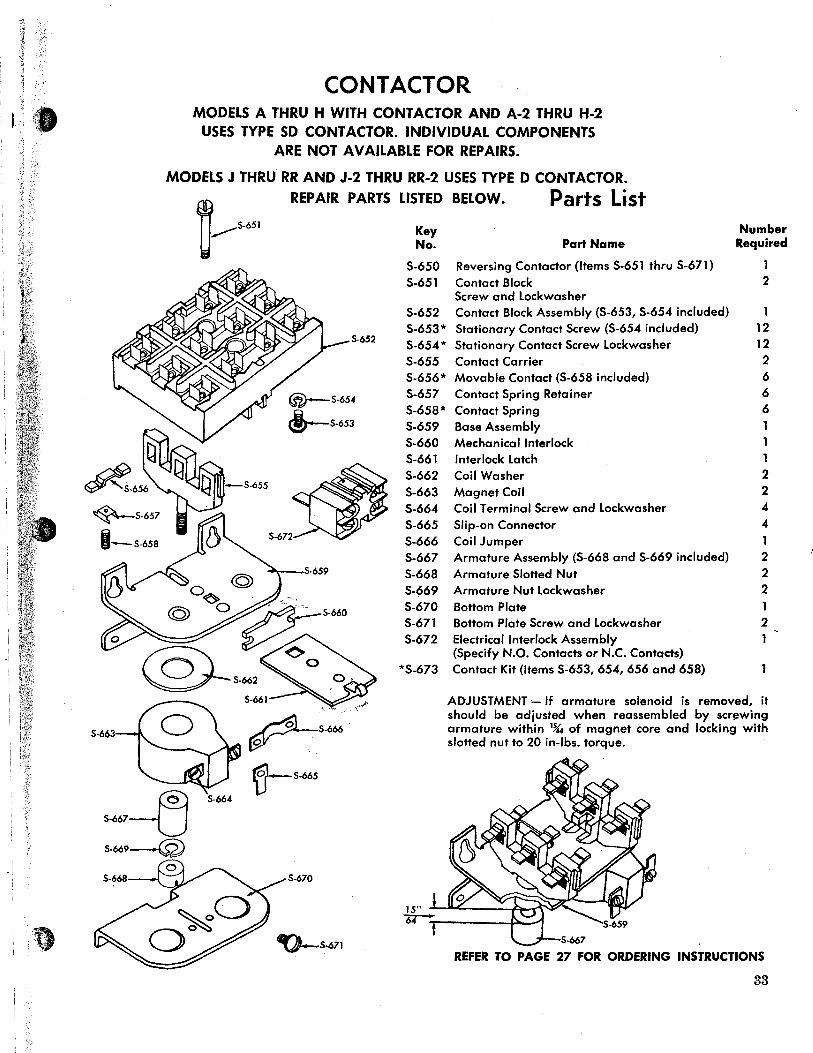
CONTACTOR MODELS A THRU H WITH CONTACTOR AND A·2 THRU H-2
USES TYPE SD CO NT ACTOR. INDIVIDUAL COMPONENTS ARE NOT AVAILABLE FOR REPAIRS.
MODELS J THRU RR AND J-2 THRU RR-2 USES TYPE D CONT ACTOR. REPAIR PARTS LISTED BELOW. Parts List
Key Number No. Part Name Required
S-650 Reversing Contactor (Items S-651 thru S-671) S-651 Contact Block 2
Screw and Lockwasher S-652 Contact Block Assembly (S-653, S-654 included) 5-653* Stationary Contact Screw (S-654 included) 12
S-652 5-654* 5tationary Contact 5crew Lockwasher 12 S-655 Contact Carrier 2 S-656* Movable Contact (5-658 included) 6 S-657 Contact Spring Retainer 6 S-658* Contact Spring 6 S-659 Base Assembly S-660 Mechanical Interlock $-661 Interlock Latch 1 5-662 Coil Washer 2 S-663 Magnet Coil 2 S-664 Coil Terminal Screw and Lockwasher 4 5-665 5lip-on Connector 4 S-666 Coil Jumper 5-667 Armature Assembly (5-668 and S-669 included) 2 5-668 Armature Slotted Nut 2 S-669 Armature Nut Lockwasher 2 S-670 Bottom Plate S-671 Bottom Plate Screw and Lockwasher 2 5-672 Electrical Interlock Assembly
(Specify N.O. Contacts or N.C. Contacts) *5-673 Contact Kit (Items S~653, 654, 656 and 658)
ADJU5TMENT- If armature solenoid is removed, it should be adjusted when reassembled by scr~wing armature within 1%4 of magnet core and locking with slotted nut to 20 in-Ibs. torque.
S-6q3
S--tJ S-664
'tl- S-665
S-669-(2)
S-670
~S-671 S-667
REFER TO PAGE 27 FOR ORDERING INSTRUCTIONS
33

Key No.
S-452
S-551
S-553
S-554
S-555
S-556
S-563
34
CONTROL STATION USED ON MODELS A THRU H, SINGLE PHASE WITHOUT CONTACTOR,
AND MODELS A-2 THRU RR-2, ALL VOLTAGES
5-551~lW5-551 'i 5-551 , e
I 5-553 5-554 5-555
Parts List
FOR MODELS A-2 THRU RR-2
[
5-563
FOR MODELS A THRU H, SINGLE PHASE WITHOUT CONTACTOR FOR MODELS A-2 THRU RR-2
Part Name
Control Station (Items S-551, S-553 thru S-556 & S-563)
Control Station Kit Consists of: 1 - Neoprene Grommet 1 - Grommet Retainer Ring 2 - Grommet Retainer Ring
Attaching Screw 6 - Cover Attaching Screw
Case
Gasket
Cover Assembly (Decal & Rocker included)
Switch Assembly
Control Station Parts Kit Consists of: 1 - Strain Cable Attaching Screw 1 - Strain Cable Attaching Screw
Washer 1 -link
Number Required
1
3 - Switch Assembly Attaching Screw 1 - link Return Spring -
Key No.
5-551
5-553 5-554 5-555
5-563
5-565
Part Name
'Control Station Kit Consists of: 1 - Neoprene Grommet 1 - Grommet Retainer Ring 2 - Grommet Retainer Ring
Attaching Screw 6 - Cover Attaching Screw Case Gasket Cover Assembly (Decal & Rocker included) Control Station Parts Kit Consists of: 1 - Spring 1 - Strain Cable Attaching Screw 1 - Strain Cable Attaching Screw
Washer 2 - Switch Attaching Pin 1 - Sliding Cam 2 ~ Spring End Support 3 - Switch Mounting Plate & Rocker
Assembly Attaching Screw 1 - Rocker Assembly 1 - Cam Return Spring Control Station Switch Kit Consists of: 3 - Switch 2 - Insulator 1 - Jumper
5-872 Control Station (Items 5-551, S-553 thru 5-555, 5-563 & S-565)
Number Required
G
a
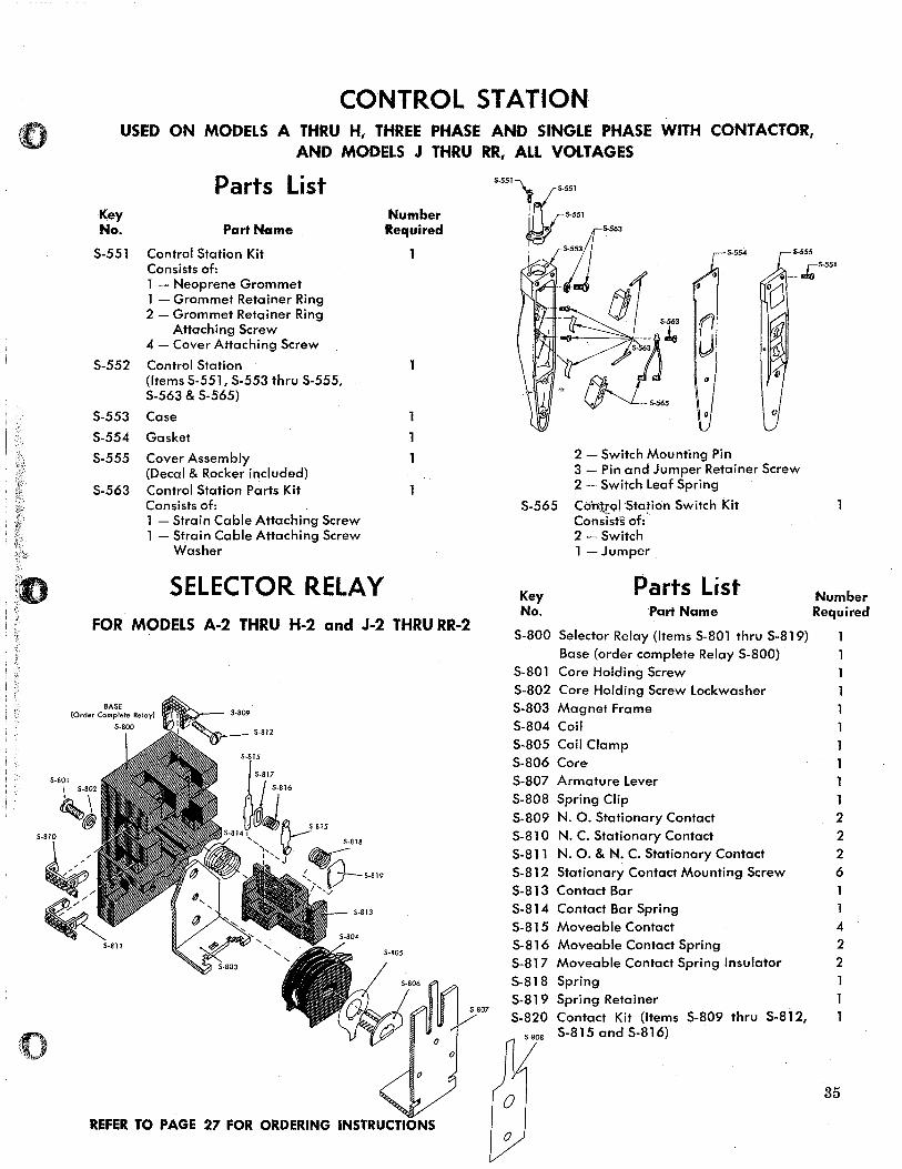
CONTROL STATION USED ON MODELS A THRU H, THREE PHASE AND SINGLE PHASE WITH CONTACTOR,
AND MODELS J THRU RR, ALL VOLTAGES
Key No.
Parts List
Part Name
S-551 Control Station Kit Consists of: 1 - Neoprene Grommet 1 - Grommet Retainer Ring 2 - Grommet Retainer Ring
Attaching Screw 4 - Cover Attaching Screw
S-552 Control Station
S-553
S-554
S-555
S-563
(Items S-551, S-553 thru S-555, S-563 & S-565)
Case
Gasket
Cover Assembly (Decal & Rocker included) Control Station Parts Kit Consists of: 1 - Strain Cable Attaching Screw 1 - Strain Cable Attaching Screw
Washer
SELECTOR RELAY
Number Required
FOR MODELS A-2 THRU H-2 and J-2 THRU RR-2
......... , ___ 5-812
5-811
5-807
REFER TO PAGE 27 FOR ORDERING INSTRUCTIONS
5-554
o
5-555
_~S-551
S-565
o
2 - Switch Mounting Pin 3 - Pin and Jumper Retainer Screw 2 - Switch Leaf Spring
Control Station Switch Kit Con~ists of i-2 - Switch 1 - Jumper
Parts List Number Key No. Part Name Required
S-800 Selector Relay (Items S-801 thru S-819) Base (order complete Relay S-800)
S-801 Core Holding Screw S-802 Core Holding Screw Lockwasher S-803 Magnet Frame S-804 Coil S-805 Coil Clamp S-806 Core S-807 Armature Lever S-808 Spring Clip S-809 N. O. Stationary Contact S-81O N. C. Stationary Contact S-811 N. O. & N. C. Stationary Contact S-812 Stationary Contact Mounting Screw S-813 Contact Bar S-814 Contact Bar Spring S-815 Moveable Contact S-816 Moveable Contact Spring S-817 Moveable Contact Spring Insulator 5-818 Spring S-819 Spring Retainer S-820 Contact Kit (Items S-809 thru 5-812,
S-815 and 5-816)
o
1 2 2 2 6
4 2 2
1 1
35

i i l
II
CHAIN CONTAINER
5-798
~S-795 --=="''v==~
A
NOTE: The Chain Container furnished by CM is engineered and designed for use with a lodestar hoist of specific size and lift. Hoist malfunction and damage to the unit can occur if other than properly engineered Chain Container is used.
Key No.
Parts List
Part Name Number Required Per Installation
S-790 Chain Container Assembly 1 (Items S-792 and S-794 thru S-798)
S-792 Chain Container Bracket Screw Lockwasher 1 S-794 Chain Container Bucket 1 S-795 Chain Container Support Link 4 S-796 Chain Container Chute 1 S-797 Chain Container Bracket 1 S-798 Chain Container Bracket Screw 1
(Special Alloy Screw) (S-792 included)
CHAIN BUCKET LENGTH VS MODEL HOIST . Min. Length
Models Lift of Bucket (Ft. Incl.) (II A" Inches)
A, AA, B, C, F, A-2, Up to 10 7 St!6
Over 10 to 20 10 St!6 AA-2, B-2, C-2, F-2
Over 20 to 30 147;6
Up to 5 7 St!6 Over 5 to 10 10 St!6
E, H, E-2, H-2 Over 10 to 15 .147;6 Over 15. to 20 16 St!6 Over 20 to 25 197;6 Over 25 to 30 22 St!6
J, JJ, L, LL, J-2, . Up to 10 10 Sli6
Over 10 to 20 14 7;6 JJ-2, L-2, LL-2
Over 20 to 30 22 st!.
Up to 5 10 %6 Over 5 to 10 147;6
R, RR, R-2, RR-2 Over 10 to 15 22 SI\ 6 Over 15 to 20 28 5t!6 Over 20 to 25 31 ''Y.6 Over 25 to 30 35''t\6
REFER TO PAGE 27 FOR ORDERING INSTRUCTIONS
36
o
~ '-
(
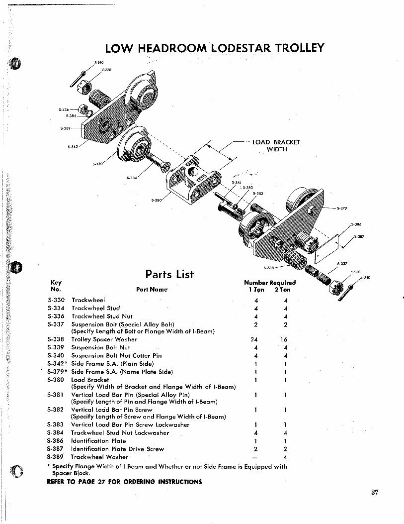
LOW HEADROOM LODESTAR TROLLEY
5-336
5-389
, , , 5-342
5-334
Parts List Key No. Part Name
S-330 Trackwheel S-334 Trackwheel Stud S-336 Trackwheel Stud Nut S-337 Suspension Bolt (Special Alloy Bolt)
(Specify Length of Bolt or Flange Width of I-Beam) S-338 Trolley Spacer Washer S-339 Suspension Bolt Nut S-340 Suspension Bolt Nut Cotter Pin S-342* Side Frame S.A. (Plain Side) S-379* Side Frame S.A. (Name Plate Side) S-380 Load Bracket
~- LOAD BRACKET WIDTH
Number Required 1 Ton 2 Ton
4 4 4 4 4 4 2 2
24 16 4 4 4 4
(Specify Width of Bracket and Flange Width of I-Beam) 5-381 Vertical Load Bar Pin (Special Alloy Pin)
(Specify Length of Pin and Flange Width of I-Beam) 5-382 Vertical Load Bar Pin Screw
(Specify Length of Screw and Flange Width of I-Beam) S-383 Vertical Load Bar Pin Screw Lockwasher 5-384 Trackwheel 5tud Nut Lockwasher 4 4 5·386 Identification Plate 1 1 5·387 Identification Plate Drive 5c~ew 2 2 5·389 Trackwheel Washer 4
* Specify Flange Width of I·Beam and Whether or not Side Frame is Equipped with Spacer Block.
REFER TO PAGE 27 FOR ORDERING INSTRUCTIONS
37
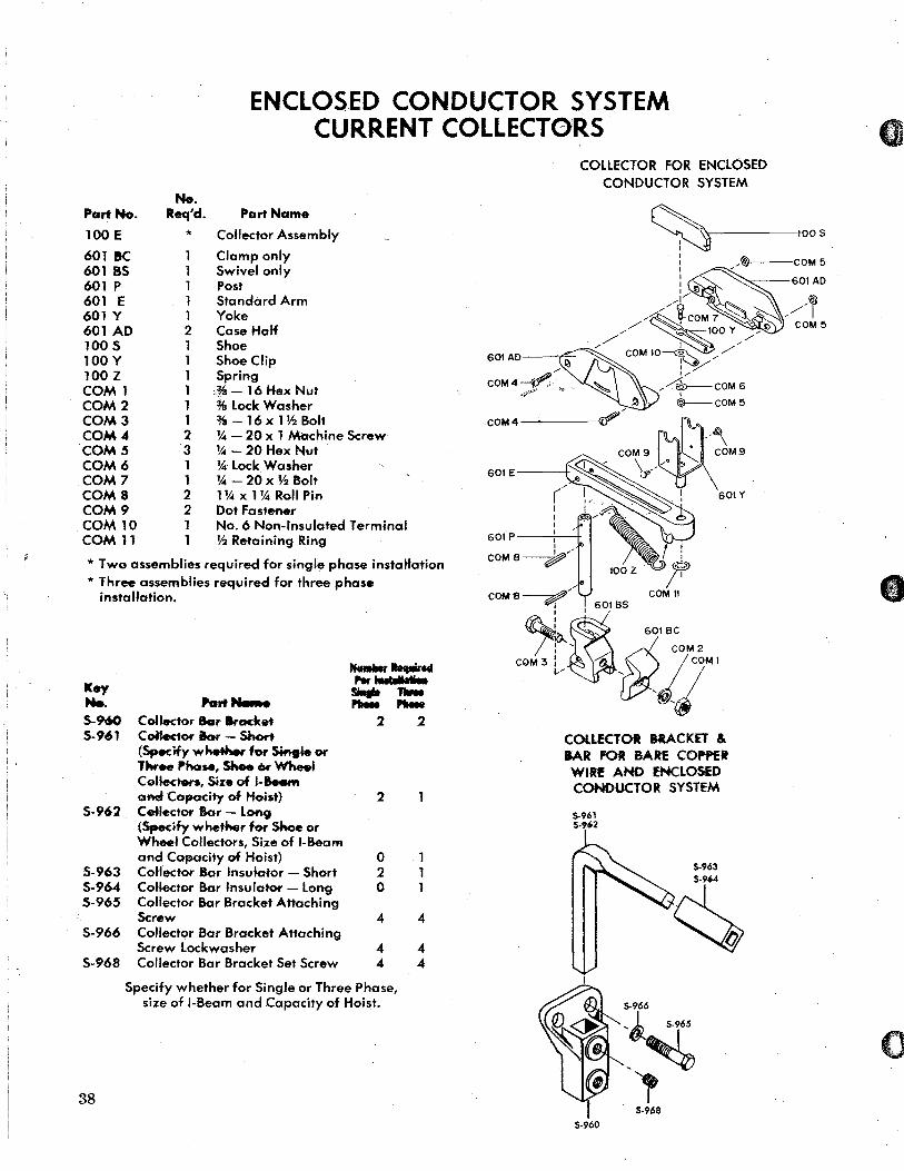
ENCLOSED CONDUCTOR SYSTEM . .
CURRENT COLLECTORS
No. Req'd.
*
Part Name
Collector Assembly
Clamp only Swivel only Post Standard Arm Yoke Case Half Shoe Shoe Clip Spring ·.MI- 16 Hex Nut % Lock Washer % - 16 x 1 V2 Bolt
Part No.
l00E
6018C 601 as 601 P 601 E 601 Y 601 AD 100 S 100 Y 100 Z COM 1 COM 2 COM 3 COM 4 COM 5 COM 6 COM 7 COMS COM 9 COM 10 COM 11
1 1 1 1 1 2 1 1 1 1 1 1 2 3 1 1 2 2 1 1
1,4 - 20 x 1 Machine Screw 1,4 - 20 Hex Nut 1,4 Lock Washer 1,4 - 20 x V2 Bolt 11,4 x 11,4 Roll Pin Dot Fastener No.6 Non-Insulated Terminal V2 Retaining Ring
* Two assemblies required for single phase instaltation * Three assemblies required for three phase
installation.
Key Me. 5-960 5-961
5-962
5-963 5-964 5-965
5-966
5-968
38
Part ..... Collector Sar arocket CoHectOf' hr - Short (Specify whether for s.... .. or Three "hoM, Shee Cw Whe.I Ceffecters, Size of J-&e.m and Capacity of Hoist) CeNactor Bor - LOfl9 (Specify whether for Shoe or Wheel Collectors, Size of I-Beam and Capacity of Hoist) Collector Bor Insulator - Short CoUector Bor Insulator - Long Collector Bar Bracket Attaching Screw Collector Bar Bracket Attaching Screw Lockwasher Collector Bar Bracket Set Screw
NaIHw ..... ,., hilt .....
SiqIe ....... ....... ...... 2 2
2
o 1 2 1 o 1
4 4
4 4 4 4
Specify whether for Single or Three Phase, size of I-Beam and Capacity of Hoist.
COLLECTOR FOR ENCLOSED CONDUCTOR SYSTEM
601 AO--"t'7-
COM4~~---
601E---+
601P I
COM8~/
COLLECTOR HACKET & aAR FOR BARf COP'PfR WIRf AND ENCLOSED CONDUCTOR SYSTEM
50961 5·'62
5·960
5·966 ,Jt 5·965
,~ l 5·968

,.';.
~' o
5·403
5·437
2 WEIGHT CENTRIFUGAL MECHANISM S·430
(Single Phase Units)
For Installation Instructions
See Page 52.
5·526
5.527
a
MODELS A, AA, B, C, E, F &'H
See Exploded View Below
5·680 TAN ELECTRIC BRAKE r 5·681 ORANGE
ASSEMBL Y ~ t===:§)
5·614 5.614
~'!("~O~"_"
See Page 44. S·650
r-------------------------------------------------"See Page 33.
TWO PIECE LOWER HOOK BLOCK MODELS A, AA, B, C, F
... ..
5·770
OPEN TYPE LIMIT SWITCHES
FOR ADJUSTMENT INSTRUCTIONS SeE PAGE 52.
o
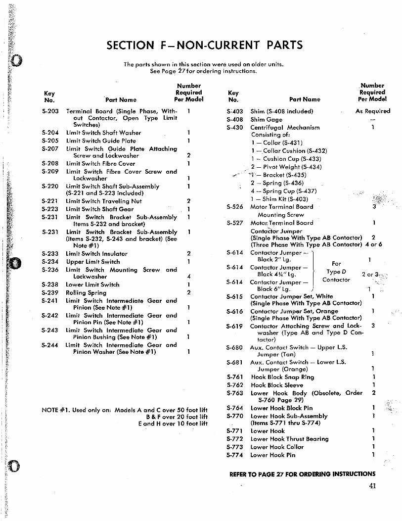
SECTION F-NON-CURRENT PARTS
The parts shown in this section were used on older units. See Page 27 for ordering instructions.
Key No. Part Name
Number Required Per Model
S-203
S-204 S-205 S-207
S-208 S-209
S-220
S-221 S-223
Terminal Board (Single Phase, Without Contactor, Open Type Limit Switches)
Limit Switch Shaft Washer limit Switch Guide Plate limit Switch Guide Plate Attaching
Screw and lockwasher Limit Switch Fibre Cover Limit Switch Fibre Cover Screw and
lockwasher Limit Switch Shaft Sub-Assembly (S-221 and S-223 included) Limit Switch Traveling Nut Limit Switch Shaft Gear
S-231 Limit Switch Bracket Sub-Assembly Items S-232 and bracket)
S-231 Limit Switch Bracket Sub-Assembly (Items 5-232, 5-243 and bracket) (5ee
Note #1) S-233 S-234 S-236
S-238 S-239 5-241
Limit Switch Insulator Upper Limit 5witch Limit Switch Mounting Screw and
lockwasher lower Limit 5witch Rolling 5pring Limit Switch Intermediate Gear and
Pinion (See Note #1) S-242 Limit 5witch Intermediate Gear and
Pinion Pin (See Note #1) 5-243 Limit Switch Intermediate Gear and
Pinion Bushing (5ee Note #1) 5-244 Limit Switch Intermediate Gear and
Pinion Washer (See Note #1)
2
2
2
4
2
NOTE #1. Used only on: Models A and Cover 50 foot lift B & F over 20 foot lift
E and Hover 10 foot lift
Key No.
5~403
S-408 S-430
5-526
5-527
S-614
S-614
5-614
S-615
S-616
5-619
5-680
5-681
S-761 S-762 S-763
S-764 5-770
5-771 S-772 S-773
Part Name
Shim (5-408 included) Shim Gage Centrifugal Mechanism Consisting of: 1 - Collar (5-431) 1 -Collar Cushion (5-432) 1 - Cushion Cup (5-433) 2 - Pivot Weight (5-434)
"'1'- Bracket (5-435) 2 - Spring (5-436) 4 - Spring Cup (5-437) 1 - Shim Kit (5-403) Motor Terminal Board
Mounting Screw MotQrTerminal Board Contoe-for Jumper
. Number Required Per Model
As Required
(Single Phase With Type AB Contactor) 2 (Three Phase With Type AB Contactor) 4 or 6
Contactor Jumper -1 Black 2/1 19.
For Contactor Jumper-
Black4%/llg . J TypeD Contactor Jumper _ Contactor
Black 6/1 19. Contactor Jumper Set, White (Single Phase With Type AB Contactor) Contactor Jumper Set, Orange (Single Phase With Type AB Contactor)
2 or 3-
1 1
Contactor Attaching Screw and lock- 3 washer (Type AB and Type D Contactor)
Aux. Contact Switch - Upper loS. Jumper (Tan)
Aux. Contact Switch - lower loS. Jumper (Orange)
Hook Block Snap Ring Hook Block Sleeve 1 lower Hook Body (Obsolete, Order 2
S-760 Page 29) lower Hook Block Pin lower Hook Sub-Assembly (Items 5-771 thru 5-774) lower Hook lower Hook Thrust Bearing lower Hook Collar
5-774 lower Hook Pin 1
REFER TO PAGE 27 FOR ORDERING INSTRUCTIONS
41
~', .

~ 1:'1:)
PLAIN SHANK HOOK & LUG SUSPENSION
5-426 5-427
o
MODELS J, L & R
LIMIT SWITCH See Exploded View Below
~ " TYPE AB CONTACTOR S-620 See Page 44.
A .. >,,! .. 'W
5-266
ELECTRIC BRAKE ASSEMBLY See Page 31.
OPEN TYPE LIMIT
SWITCHES
FOR ADJUSTMENT INSTRUCTIONS SEE PAGE 52.
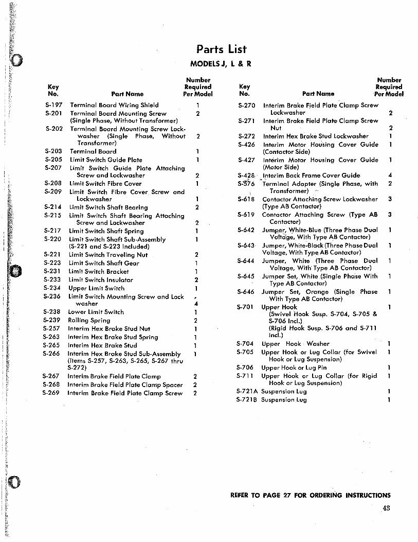
Parts List MODELS J, L & R
Key No. Part Name
Number Required Per Model
5-197 Terminal Board Wiring Shield 1 5-201 Terminal Board Mounting Screw 2
(Single Phase, Without Transformer) 5-202 Terminal Board Mounting Screw lock-
washer (Single Phase, Without 2 Transformer)
5-203 Terminal Board 5-205 5-207
5-208 5.209
5-214 5-215
5-217 5-220
5-221 5-223 5-231 5-233 5-234 5-236
5-238 5-239 5-257 5-263 5-265 5-266
5-267 5-268 5-269
limit Switch Guide Plate limit Switch Guide Plate Attaching
Screw and lockwasher limit Switch Fibre Cover limit Switch Fibre Cover Screw and
lockwasher limit Switch Shaft Bearing limit Switch Shaft Bearing Attaching
Screw and lockwasher limit Switch Shaft Spring limit Switch Shaft Sub-Assembly (S-22l and 5-223 included) limit Switch Traveling Nut limit Switch Shaft Gear limit Switch Bracket limit Switch Insulator Upper limit Switch limit Switch Mounting Screw and lock
washer lower limit Switch Rolling Spring Interim Hex Brake Stud Nut Interim Hex Brake Stud Spring Interim Hex Brake Stud Interim Hex Brake Stud Sub-Assembly (Items 5-257, 5-263, 5-265, 5-267 thru 5-272) Interim Brake Field Plate Clamp Interim Brake Field Plate Clamp Spacer Interim Brake Field Plate Clamp Screw
2
1 2
2
2
1
2
4 1 2 1 1
2 2 2
Key No. Part Name
Number Required Per Model
5-270 Interim Brake Field Plate Clamp Screw lockwasher 2
5-271 Interim Brake Field Plate Clamp Screw N~ 2
5-272 Interim Hex Brake Stud lockwasher 5-.426 Interim Motor Housing Cover Guide
(Contactor Side) 5-427 Interim Motor Housing Cover Guide
(Motor Side) 5-428 Interim Back Frame.Cover Guide S~'576 ""Terminal Adapter (Single Phase, with
t
5-618
5-619
5-642
5-643
5-644
5-645
5-646
5-701
Transformer) Contactor Attaching Screw lockwasher (Type AB Contactor) Contactor Attaching Screw (Type AB
Contactor) Jum,peF, White-Blue (Three Phase Dual
Voltdge, With Type AB Contactor) Jumper, White-Black (Three Phase Dual Voltage, With Type AB Contactor) Jumper, White (Three Phase Dual
Voltage, With Type AB Contactor) Jumper Set, White (Single Pha'se With
Type AB Contactor) Jumper Set, Orange (Single Phase
With Type AB Contactor) . Upper Hook
(Swivel Hook Susp. 5-704, 5-705 8. 5-706 Incl.) (Rigid Hook Susp. 5-706 and 5-711 Incl.)
5-704 Upper Hook Washer 5-705 Upper Hook or lug Collar (for Swivel
Hook or lug Suspension) 5-706 Upper Hook or lug Pin 5-711 Upper Hook or lug Collar (for Rigid
Hook or lug Suspension) S-721A Suspension lug 5-721 B Suspension lug
4 2
3
3
REFER TO PAGE 27 FOR ORDERING INSTRUCTIONS
43
S-622
5-636 ----->*"_
S-637
S-638
: 5_451/~
44
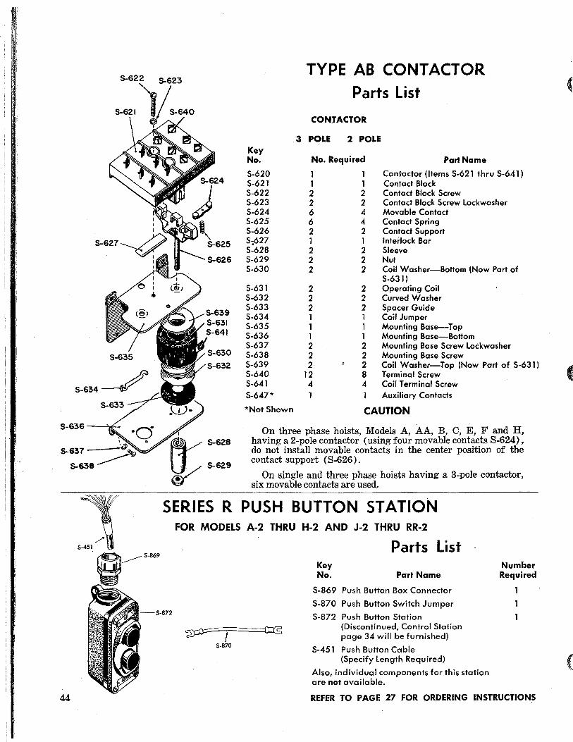
TYPE AB CONTACTOR
Parts List
CONTACTOR
.3 POLE 2 POLE Key No. No. Required Part Name
5-620 1 1 Contactor (Items 5-621 thru 5-641) 5-621 1 1 Contact Block 5-622 2 2 Contact Block 5crew 5-623 2 2 Contact Block 5crew Lockwasher 5-624 6 4 Movable Contact 5-625 6 4 Contact 5pring 5-626 2 2 Contact 5upport 5-;627 1 1 Interlock Bar 5-628 2 2 51eeve 5-629 2 2 Nut 5-630 2 2 Coil Washer-Bottom (Now Part of
5-631 ) 5-631 2 2 Operating Coil 5-632 2 2 Curved Washer 5-633 2 2 5pacer Guide 5-634 1 1 Coil Jumper 5-635 1 1 Mounting Base--Top 5-636 1 1 Mounting Base--BoHom 5-637 2 2 Mounting Base 5crew Lockwasher 5-638 2 2 Mounting Base 5crew 5-639 2 2 Coil Washer-Top (Now Part of 5-631) 5-640 12 8 Terminal5crew 5-641 4 4 Coil Terminal 5crew 5-647* 1 Auxiliary Contacts
*NotShown CAUTION
On three phase hoists, Models A, AA, B, C, E, F and H, having a 2-pole contactor (using four movable contacts 8-624), do not install movable contacts in the center position of the contact support (8-626).
On single and three phase hoists having a 3-pole contactor, six movable contacts are used.
SERIES R PUSH BUTTON STATION FOR MODELS A-2 THRU H-2 AND J-2 THRU RR-2
Parts List
~=:::;::I ==::===Ic:::(5
5-870
Key No. Part Name
5-869 Push Button Box Connector
5-870 Push Button Switch Jumper
5-872 Push Button Station (Discontinued, Control Station page 34 will be furnished)
5-451 Push Buffon Cable (Specify Length Required)
Also, individual components for this station are not available.
Number Required
REFER TO PAGE 27 FOR ORDERING INSTRUCTIONS
C
C
c
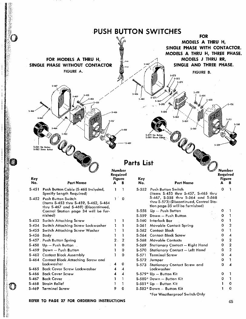
·PUSH BUTTON SWITCHES
FOR MODELS A THRU H, SINGLE PHASE WITHOUT CONTACTOR
FIGURE A.
5-459
5-465
FOR MODELS A THRU H,
SINGLE PHASE WITH CONTACTOR. MODELS A THRU H, THREE PHASE.
MODELS J THRU RR, SINGLE AND THREE PHASE.
FIGURE B.
Parts List Number Number Required Required
Key Figure Key Figure No. Part Name A B No. Part Name A B
S-451 Push Button Cable (S-468 Included, S-552 Push Button Switch 0 Specify length Required) (Items S-453 thru S-457, S-465 thru
S-452 Push Button Switch 0 S-467, S-558 thru S-564 and S-568
(Items S-453 thru S-459, S-462, S-464 thru S-573) (Discontinued, Control Sta-
thru S-467 and S-469) (Discontinued, tion page 35 will be furnished)
Control Station page 34 will be fur- S-558 Up - Push Button 0 nished) S-559 Down - Push Button 0
S-453 Switch Attaching Screw S-560 Interlock Bar 0 1 S-454 Switch Attaching Screw lockwasher S-561 Movable Contact Spring 0 2 S-455 Switch Attaching Screw Washer S-562 Contact Block 0 S-456 Body 1 1 S-564 Contact Block Screw 0 4 S-457. Push Button Spring 2 2 S-568 Movable Contacts 0 2 S-458 Up - Push Button 0 S-569 Stationary Contact - Right Hand 0 2 S-459 Down - Push Button 0 S-570 Stationary Contact - left Hand 0 2 S-462 Contact Block Assembly 0 S-571 Terminal Screw 0 4 S-464 Contact Block Attaching Screw and S-572 Jumper 0 1
lockwasher 4 0 S-573 Stationary Contact Screw and 0 4 S-465 Back Cover Screw lockwasher 4 4 lockwasher S-466 Back Cover Screw 4 4 S-579* Up - Button Kit 0 S-467 Back Cover S-580* Down - Button Kit 0 T S-468 Strain Relief S-581 * Up - Button Kit 0 S-469 Terminal Screw 9 0 S-582* Down - Button Kit 0
*For Weatherproof Switch Only
REFER TO PAGE 27 FOR ORDERING INSTRUCTIONS 45
1!'f5
_
17J
5-173~
5-172
5-479 --iQl '. _
~ r 5-516 5-515
~~5-167 5-478
5-552
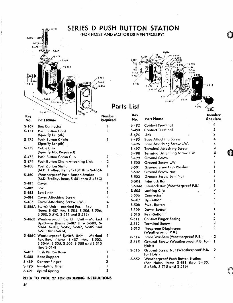
SERIES 0 PUSHBUTTON STATION
5-482
5-483
(FOR HOIST AND MOTOR DRIVEN TROLLEY)
'1 5-506
5-492
5-489
Parts List
5-494
5-491
Key No. Part Name
Number Required
Key No. Part Name
Contact Terminal Contact Terminal Link
Number Required
5-167 5-171
5-172
5-173
5-478 5-479 5-480
5-480
5-481 5-482
Box Connector Push Button Cord (5pecify Length) Push Button Chain (5pecify Length) Cable Clip (5pecify No. Required) Push Button Chain Clip Push Button Chain Attaching Link Push Button 5tation (M.D. Trolley, Items 5-481 thru 5-486A Weatherproof Push Button 5tation (M.D. Trolley, Items 5-481 thru 5-486C) Cover Box
5-483 Box Liner 5-484 Cover Attach.ing Screw 5-485 Cover Attaching Screw L.W. 5-486A 5witch Unit - marked For. -Rev.
(Items 5-487 thru 5-504, 5-505, 5-506, 5-508, 5-510, 5-511 and 5-512)
5-486B Weatherproof 5witch Unit - Marked Up-Down (Items 5-487 thru 5-503, 5-504A, 5-505, 5-506, 5-507, 5-509 and 5-511 thru 5-514)
5-486C Weatherproof Switch Unit - Marked For.-Rev. (Items 5-487 thru 5-503, 5-504A, 5-505, 5-506,5-508 and 5-510 thru 5-514)
5-487 Push Button Base 5-488 Base 5upport 5-489 Contact Finger 5-490 Insulating Liner 5-491 5piral Spring
2
1 4 4
1 1 2 1 2
REFER TO PAGE 27 FOR ORDERING INSTRUCTIONS
46
5-492 5-493 5-494 5-495 5-496 5-497-5-498 5-499 5-500 5-501 5-502
Base Attaching 5crew Base Attaching 5crew L.W. Terminal Attaching Screw Terminal Attaching 5crew L.W. Ground 5crew Ground 5crew L.W. Ground 5rew Cup Washer Ground 5crew Nut
5-503 Ground 5crew Jam Nut 5-504 Interlock Bar 5-504A Interlock Bar (Weatherproof P.B.) 5-505 5-506 5-507 5-508 5-509 5-510 5-511 5-512 5-513
5-514 5-515
5-516
5-552
Locking Clip Connector Up-Button Fwd.-Button Down-Button Rev.-Button Contact Finger Spring Terminal 5crew Neoprene Diaphragm (Weatherproof P.B.) Brass Washers (Weatherproof P.B.) Ground 5crew (Weatherproof P.B. for Hoist) Ground 5crew Nut (Weatherproof P.B. for Hoist) Weatherproof Push Button Station (For Hoist, Items 5-481. thru 5-485, 5-486B, 5-515 and 5-516)
2 2
'2 4 4 4 4
1
1 2
1 1 2 4
2
2
o

SERIES E PUSH BUTTON STATION (FOR HOIST WITH MOTOR DRIVEN TROLLEY)
5-173~ 5-172
5-171
5_479~ 1"'"
~ 5-167
5-480
5-281
5-278
5-282
Key No.
5-167 5~ 171 5-172 S-"173 S-278 S-279 S-280 S-281
S-282 S-283 S-284 S-285 S-286 S-287 S-288
S-289
S-290 S-291 S-292 S-293 S-294 S-295 S-296 S-297 S-298 5-299 S-300 S-479 S-480
REFER TO PAGE 27 FOR ORDERING INSTRUCTIONS
5-298
~5-300
~5-284 5-2
~~;::::~;::_~::", ~~ 5-295
5-295~ Gb ~'(l) < e" ~5-280 5-299/~/ Q! ~ 0 ~ 5-279
5-297 ~7 ~~5-287 5-296 / / ~ID::5-292
5-294 ~ I 5-291
5-290 Q.J ,,~ 5-280~'~
Parts List 5-279/~ Part Name
Number Required
Box Connector Push Button Cord (Spe,£ify'length Required) Push Button Chain (Specify length Required) Cable Clip (Specify No Required) Cover Attaching Screw 2 Switch Insert Unit Attaching Screw and loW. 4 Switch Insert Unit Attaching Screw Flat Washer 4 Indicator Plate (Specify Plate Required - Up, 6 Down, Hoist, Fwd., Rev. and Trolley) Indicator Plate Drive Screw (2 per Plate) 12 Insulator Shield Ground Wire Solderless Terminal Sheet Steel Enclosure (Frame and Cover included) 1 Switch Unit Insert (Items S-287 thru S-300) 2 Push Button Guide Attaching Screw and loW. 2* Stationary Contact Attaching Screw and loW. - 4*
long Stationary Contact Attaching Screw and loW. - 4*
Short Stud lockwasher Push Button Tapered Spring, Top Push Button Guide Compression Spring, Center Stationary Contact Movable Contact Compression Spring, Bottom Base Terminal Nut Stud Push Button Chain Attaching link Push Button Station (Items S-278 thru S-286)
2* 2* 2* 1* 2* 8* 2* 2* 1* 8* 2 2
*Number required for one switch unit insert
47

MOTOR DRIVEN TROLLEY
ssss-ssS-5_"'7<.-./ 5-S-5-IAS-----, 5-1 .. "-----.-, ....
See Pages 45 and 46 for Push Button Stations for Motor Driven Trolleys.
Parts List
Key Number Key Number No. Required Part Name No. Required 5-133 1 Contactor Bracket 5-156 1 5-134 1 Trolley Load Bar 5-157 1 5-135 1 Push Button Chain Eyebolt 5-158 1 5-136 1 Contactor Box and Cover 5-159* 1 5-137 4 Contactor Box Attaching 5crew 5-160 1 5-138 2 Pu~h Button Chain Eyebolt Washer 5-161 2 5-139 2 Push Button Chain Eyebolt Nut 5-162 2 5-140 3 Contactor Attaching 5crew 5·163 2 5-141 4 Contactor Box Attaching 5crew 5-164 1
Washer 5-165 3 5-142 3 Contactor Attaching Screw Lockwasher 5-166 3 S-143 4 Contactor BoxAttach.Screw Lockwasher 5-168 1 5-144 4 Contactor Box Attaching Screw Nut 5-169 1 5·145 3 Contactor Attaching 5crew Nut 5-171 1 5-146 1 Box Connector 5-147* 1 Cable Clamp 5-172 5-148 * 1 Cable Clamp Screw 5-149* 1 Cable Clamp Screw Lockwasher 5-173 5·150 1 . Plug and Body 5-155 1 Cable (Contactor Box to Trolley 5-174 2
Motor) 5-175 10
48
+ '. .' + <_.j (.' L~----> +
IDLER GEARING
-158 -161 -162 -163 -620 OR -650
..... _-" 160
-146
Part Name Cable (Contactor Box to Hoist) Power Cord Box Connector Contactor Jumper Transformer and Bracket Assembly Transformer Attaching 5crew Transformer Attaching Screw Lockwasher Transformer Attaching 5crew Nut Brake Cover Brake Cover 5crew Brake and Motor Cover Screw Lockwasher Box Connector Box Connector Push Button Cable (Specify Length Required) Push Button Chain (5pecify Length Required) Push Button Cable Clip (Specify No. Required) Brake Spring Spacer Washer
-.' W
0' -'.-'-': -.- ~~.l

~~
»Ia ;e·
Key No. Part Name
Brake Hub Key
Number Required
5-176 5-177 5-178 5-179 5-180 5-181 5-182 5-183 5-184 5-185 5-186 5-187 5-188 5-189 5-190 5-191 5-192 * 5-194 5-195 5-249
5-250
5-251
S-252 S-253 S-256
5-257 S-258 5-259 5-260 5-261 5-262 5-314 5·315 5-330 5-331 5-332 S-333 5-334 5-335
Cover Gasket (Weatherproof Units) Motor End Cover Motor Cover Screw Trolley Motor (5-364 included) Frame with Stator Shaft and Rotor (5-364 included) End Bell (Inner) End Bell (Outer) Ball Bearing (Pinion End) Ball Bearing (Brake Hub End) Spring Washer Snap Ring Bearing Cap Bearing Cap Screw Motor thru Bolt with lockwasher Rubber Bushing (For Brake leads) Brake Hub (Splined) Brake Hub Snap Ring (Splined Shaft) Electric Brake Assembly Complete with Cover (Items 5-164, 5-165, 5-166, 5-176,5-250,5-252,5-253,5-314 and 5-315) -
Electric Brake Assembly (Items 5-174, 5-175, S-251, 5·256 thru 5·261) Brake Base Plate and Stud Sub·
Assembly Brake Attaching Screw Lockwasher Brake Attaching Screw Brake Field Sub.Assembly(S·262
included) -'; c:;\ Brake Stud Nut" -.;,'; .. .. '".;~;."
Brake Coil Retainer Strap; Brake Coil Brake Armature Sub.As .• embly _ Brake Friction Disc Sub-Assembly_ Brake 5hading Coil Brake Hub (Keyed) Brake Hub Snap Ring (Keyed Shaft) Trackwheel (5-331 included) Trackwheel Bearing Cup Trackwheel Bearing Cone Trackwheel Bearing Seal Washer Trackwheel Stud Trackwheel 5tud Collar
S-336 Trackwheel Stud Nut 5-337 Hoist Suspension Bolt 5-338 Trolley Spacer Washer 5-339 Suspension Bolt Nut 5·340 Suspension Bolt Nut Cotter Pin 5·341 Side Frame Sub-Assembly (Motor side)
*Not Shown
2
3
1 4 4
2 2 1
2
1 1 1 2 1 1 4 8 8 8 4 4 4 2
62 4 4
REFER TO PAGE 27 FOR ORDERING INSTRUCTIONS
Key No. Part Name
Number Required
S·342 5-343 5-344 S-345 5-346 5-347 S-348 S-349 5-350 S-351 S-352 S-353 5-354 5-355 S·356
Side Frame Sub-Assembly (Plain side) Trackwheel Gear (5-344 included) Trackwheel Gear Groov Pin Trackwheel Gear Pinion Trackwheel Pinion Key Trackwheel Pinion Shaft Trackwheel Pinion lockwasher Trackwheel Pinion Nut Trackwheel Pinion Spacer Pinion Bearing Sleeve Pinion Shaft Ball Bearing Driven Gear Key Pinion Bearing Spacer Driven Gear Intermediate 5haft Ball Bearing (5ide Frame End)
5·357,,, Intermediate Pinion 5·358 Intermediate Bearing Spacer 5·359 Intermediate Shaft Ball Bearing
5·360 5·361 5·362 5·363 5·364 5·365 5·366 5·367 5·368 5·369 5·370 5·371 5·372 5·373
5·374 5·375 5·376 5·377 S·378 5·390* 5·391 * S-392*
S-393*
5-394* 5-396 5-397 S-398
5-399
5-407* S-479 S-614 * S-620 S-650 S-907 S-908 S-909
(Motor End) Intermediate Pinion 5crew lockwasher Intermediate Pinion Nut Intermediate Gear Motor Pinion Motor Pini.on Groove Pin Gear Housing Gear Housing Gasket Gear Housing 5crew lockwasher Gear Housing Screw Motor End Bell Gasket Terminal Box Terminal Box Cover Terminal Box Attaching Screw Terminal Box Attaching 5crew lock-
washer Box Connector Idler Pinion Idler Pinion Bearing Idler Pinion Washer Idler Pinion Cotter Pin Capacitor (Single Phase) Capacitor Housing (Single Phase) Capacitor Housing Screw (Single Phase) Capacitor Housing Screw lockwasher (Single Phase) Capacitor lead Grommet. Motor Reverse Switch (Single Phase) Centrifugal Switch (Single Phase) Reverse Switch Attaching SCFew (Single Phase) Reverse Switch Attaching Screw lock·
washer (Single Phase) line Connector (Specify No. Req/d.) Push Button Chain Attaching link Contactor Jumper, Black Contactor Type AB (See Page 44) Contactor Type D (See Page 33) Suspension lug Screw Nut Suspension lug 5crew lockwasher Suspension lug Screw
1 2 4 1 1 1 1 1 1 1 2 1 1 1 1
1 1 1 1 1 1 1 4 4 1 1 1 3 3
1 2 2 2 2 1 1 2
2
1 1 1 2
2
2 6 1 1 2 2 2

S-968
PARTS. SEE PAGE 38
REFER TO PAGE 27 FOR ORDERING INSTRUCTIONS
50
TANDEM TROLLEY
Key No.
S-901 S-902 S-903 S-904 S-905 S-906 S-907 S-908 S-909 S-910 S-911 S-912 S-913 S-914 S-915 S-960 S-965 S-966 S-967 5-968 S-969
FOR INSTALLATION INSTRUCTIONS, SEE PAGE 53
S-911
Parts List
Part Name
Trackwheel Stud Nut Trackwheel Stud Lockwasher Side Frame Trackwheel Trackwheel Stud Load Bar Suspension Lug Screw Nut Suspension Lug Screw Lockwasher Suspension Lug Screw Frame Screw (Specify Screw Length Required) Spacer Trolley Pin Block Cotter Pin Frame Screw Nut Lockwasher Frame Screw Nut Collector Bar Bracket Collector Bar Bracket Bolt Collector Bar Bracket Bolt Nut Lockwasher Collector Bar Bracket Bolt Nut Collector Bar Bracket Set Screw Steel Clamp
Number Required
4 4 4 4 4 1 2 2 2 4 16 2 2 4 4 2 2. 2 2 4 1

S-388
LOW HEA.DROOM LODESTAR TROLLEY Parts List
S-331
Key No.
5-330* 5-331 * 5-332* 5-333* 5-334* 5-335* 5-336* 5-337
5-385 5-388*
Part Name
Trackwheel (5-331 included) Trackwheel Bearing Cup Trackwheel Bearing Cone Trackwheel Bearing 5hield Trackwheel Stud Trackwheel5pacer Trackwheel 5tud Nut Cross ~olt and Nut (Obsolete, order 5-337 Page 37) Cross Bolt Nut lockwasher Trackwheel 5tud Snap Ring
Number Required
4 8 8 8 4 4 4 2
2 4
CAST IRON TRACKWHEEL
S-330 *When ordering specify that part is for a 2 ton trolley with cast iron wheels.
. 'Or'
S-335
For other trolley parts, see Page 37
REFER TO PAGE 27 FOR ORDERING INSTRUCTIONS
Key No.
5·791
5·792 5·793
5·794 5·795
CHAIN CONTAINER
Parts List
Part Name
Chain Container Bracket Screw (Special Alloy Screw) (5-792 included) Chain Container Bracket Screw lockwasher Chain Container Bracket (Obsolete Order 5-792 and 5·795 thru 5-798, page 36)
Number Required
Chain Container Bucket 1 Chain Container Support link 2
REFER TO PAGE 27 FOR ORDERING INSTRUCTIONS
51

Adiustment of Open Type
Limit Switches Use the general instructions given on pages 16 and 17 for ENCLOSED TYPE LIMIT SWITCHES. However, use Table II and Figures 19 and 20 be.low in place of Tableland Figures 14 and 15 referred to in the text.
TABLE ][
OPEN TYPE LIMIT SWITCHES Hook Travel Per Notch of Limit Switch Nut
Hook limit Trovel
lifting length Switch Per Model Speed of Max. Gear Notch A 8
No. (FPM) lift (Ft;) Reduction (In.) (In.) (links)
E, H 8 o thru 10 Single !4 PA 6 Over 10 thru 45 Double % 3 6
8, F 16 o thru 20 Single ~6 1 '12 6 Over 20 thru 45 Double Hi6 2 6
8 16 Over 45 thru 90 Double 1~6 2 6
A,C 32 o thru 50 Single Va 3 6 Over 50 thru 70 Double 2% 4'12 6
C 32 Over 70 thru 90 Double 2% 4 '12 6
AA 60 o thru 90 Single 1% 8 6
32 o thru 20 Worm * 2'12 8 Over 20 thru 30 Worm * 2'12 8
16 o thru 20 Worm * 2'12 8 Over 20 thru 45 Worm * 4 8
R 8 o thru 10 Worm 'Ys 2'12 8 Over 10 thru 25 Worm 'Ys 2'12 8 Over 25 thru 45 Worm * 2'12 8
FIGURE 19. OPEN TYPE LIMIT SWITCHES, MODELS A THRU H.
1. Limit switch 4. Guide plate 2. Fiber cover 5. Screws and lockwashers 3. Traveling nuts 6. Limit switch shaft
(Do not order parts by these numbers. See parts list.)
FIGURE 20. OPEN TYPE LIMIT SWITCHES, MODELS J, LAND R.
52

Reversing Switch and Shim Gage
For 2-Welght Typo Centrifugal Mechanism If the actuating flng'cr or contacts of the revers
ing switch (S·404) have been damaged, replace the switch. It is held to the motor cover by screws and lock washers (S"406). R(~move the shims (S-403), if any. A complete set of shims (S-403) with the shim gage (S.408) will be furnished with a replacement switch or cClHrifugal mechanism.
To determine the total thickness of shims (S-403) required under the reversing switch (S-404), clamp the rotor (S-413) in a vice in a vertical position (be sure to use copper or soft jaws in vice) with the centrifugal mechanism up and completely assembled on the rotor shaft as shown in Figure 21. (The bracket (S-435) must be pressed against the shoulder on the rotor shaft.) Remove the reversing switch (S-404) from the motor housing cover and place the base of the switch against the face of the mechanism collar. (This places the switch opposite its normal operating position.) Depress the centrifugal mechanism until the collar stops on the cushion. In this position the springs are compressed and the weights are out from the bracket and full load speed operating conditions are duplicated.
Place the fiber gage (S-408) over the end of the rotor shaft with the step in the gage against the shaft shoulder as shown. The proper shim thickness is the greatest thickness of shims wilich can be inserted between the gage and the switch finger without deflecting the finger. Shims are provided in 0.010,0.020,0.030,0.040 and 0.050 inches. If the gage deflects the contact finger or the space between the gag(' is less than the thinnest shim (0.010 inch), no shim is required.
FIGURE 21. GAGING REVERSING SWITCH Two-weight centrifugal mochanlsm
FIGURE 22. TANDEM TROLLEY
1. Loa~ baL_ 4. Frame screws 2. Side frames 5. Suspension lug 3. Spac~rs screws
(Do not order parts by these numbers. See parts list.)
Determine the size beam on which the trolley is to be used. Trolley,s are adjusted for beam size by the arrangement of spacers' either outboard or inboard of the side frames. Refer to Fig. 23 for spacer arrangement for beam sizes within the range of the trolley. Arr~nge the side frames, load bar, and spacers on
the bolts according to Fig. 22 for proper beam size. Do not assemble nuts and lockwashers to the bolts. Assemble trolley to beam by sliding one side frame of each head out far enough to allow the wheels to clear the beam flange. Draw the side frames together, assemble lockwashers and nuts, and tighten securely. To compensate for I-beam tolerances, it may be necessary to shift one spacer from A to B or B to A on one side. The distance between trackwheel flanges should be Ys" larger than the beam flange width.
Remove the two suspension lug screws from the load bar, insert the hoist suspension lug, and replace the suspension screws. Add lock washers and nuts to the suspension screws. Tighten all nuts securely.
BEAM NO. OF SPACERS SIZE A B
4"-7.7 4 0
5"-10.0 3 1
6"-12.5 2 2
7"-15.3 1 3
A B B A 8"-18.4 0 4
FIGURE 23. TANDEM TROLLEY MOUNTING DIAGRAM
53

FIGURE 24. WHEEl AND SHOE COLLECTORS
Current collectors are furnished in both the wheel type (5) (Fig. 24) and shoe type (4) for use with the trolley and overhead power wires. On Tandem Trolleys the brackets (3) are attached to the load bar of the trolley by the special alloy screws provided with the collectors which replace the suspension lug screws (5) (Fig. 22) provided with the trolley. On Low Headroom Lodestar Trolleys the bracket is attached by screws inserted into tapped holes in the side frames. The collector bar and insulators are positioned in the bracket as shown in Fig. 25 to fit different sizes of I-beams and locked with set screws. On a three-phase installation two collectors are mounted on one side of the hoist using a long bar and a long insulator. After positioning the collectors, measure the length of power cable needed to reach the farthest collector, allow for connecting the wire to the collector shunt screw and cut off the power cable. Strip back the insulation as required, cut off the green (ground) wire and attach remaining wires to the collector shunt screws.
1. Insulator 4. Shoe type collector 2. Collector bar 5. Wheel type collector 3. Collector bracket 6. Shunt screw
(Do not order parts by these numbers. See parts list.)
COLLECTOR MOUNTING DIAGRAM - SINGLE AND THREE PHASE
WHEEL TYPE COLLECTORS SHOE TYPE COLLECTORS
t 3 1/4
8~41
~ "lib UI IP
8-.k-41~ 0- II
54
STD. I TYPE COLLECTOR BEAM SIZE WHEEL SHOE
4 B C 5 B C 6 C C 7 C A 8 C A
FOR USE WITH THE
LODESTAR ELECTRIC CHAIN HOIST
AND TANDEM TROLLEY
II II __ •• Jt. ... .:u-"
... r--I..--J::. ___ .. _ J'"
HOIST IS GROUNDED TO TROLLEY FOR PROTECTION. PROVIDE LEAD WIRE FROM
TRACK TO SUITABLE GROUND. MOUNT 2 COLLECTORS ON
ONE SIDE OF HOIST AS SHOWN WHEN 3 PHASE IS REQ'D.
t17i\"JI ~vr.l
@ ~
MOUNTING POSITION FOR COLLECTOR BAR AND BRACKET
A
B
FIGURE 25.
---1 n~ ---{--j~
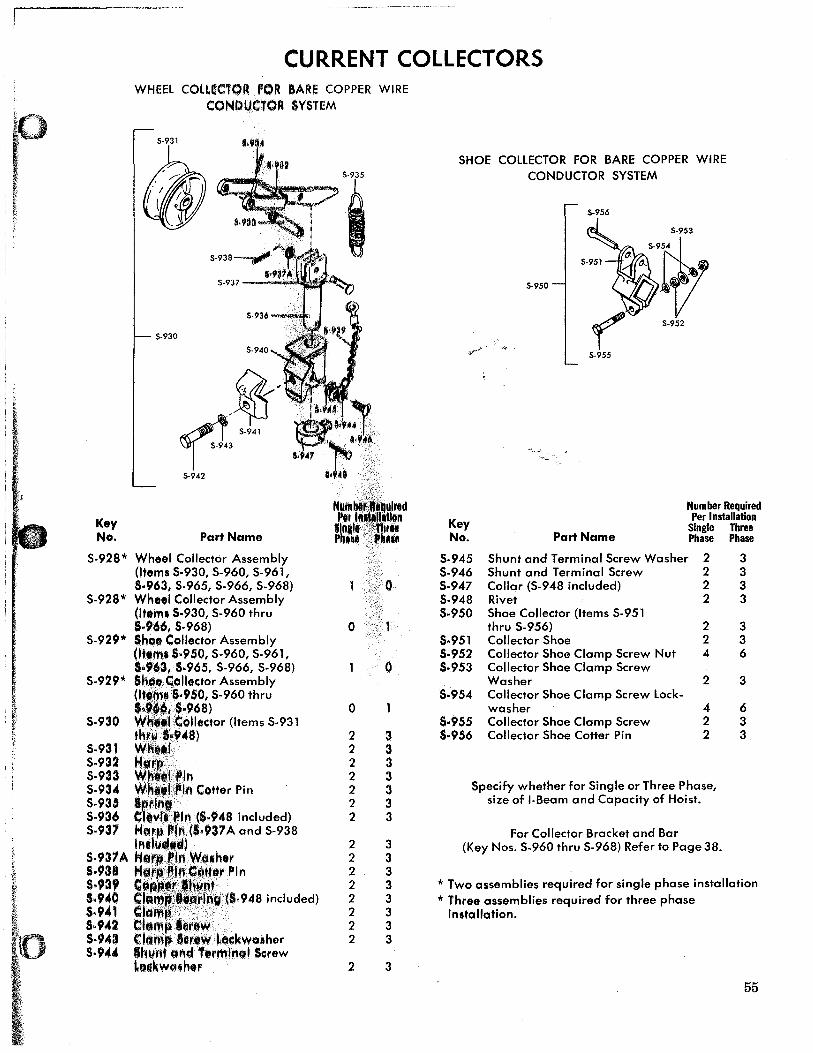
I CURRENT COLLECTORS
WHEEl COLLECTOR paR BARE COPPER WIRE CONDUCTOR SYSTEM
5-931
5-937 - ..... _~;}#~"',
Key No.
5-930
~/ ~1' 5-941 _I 5-943
5-942
Part Name
5·928* Wheel Collector Assembly (Items 5·930, 5·960, 5·961, 5.963, 5.965, 5·966, 5·968)
5·928* Wheel Collector Assembly (Item. $·930, 5-960 thru '.966, 5-968)
5·929* Shoo Collector Assembly (Item. 5·950, 5-960, 5-961, 5.963, 5.965, 5-966, 5-968)
5·929* Shol.Coliector Assembly
5-930
5.931 5-932 5·933 5-934 5·935 5-936 5-937
(It ·5.950, 5-960 thru S ,$·968) ,.1 Collector (Items 5·931 ,kl'l,Ii"48) Wh •• t H
11~ln . . IPln Cotter Pin apr!ri'f Cltv(fPln ($·948 included) Harp"l" (1.937 A and S·938 IntJllJchl~U
5·93?A M.fp~ln Wtuhor 5·938 Hg.l'lf~1 .. U.,. Pin 5.939 C:'PP,_~._."nr .. $.940 ¢lilmp!.~ .. rfn. (8.948 included) 5·941 Clamp:'· $·942 Clampl.row .. , $·943 Clomp 1III'IWLClckwasher S·944 Ihunt and T."mlnol Screw
LOClkwcuh,r
0
0
2 2 2 2 2 2 2
2 2 2 2 2 2 2 2
2
0
0
3 3 3 3 3 3 3
3 3 3 3 3 3 3 3
3
5HOE COLLECTOR FOR BARE COPPER WIRE CONDUCTOR 5Y5TEM
S-956
5-950
""':...~~ .. ~.~ ....
Number Required
Key Per Installation
Single Three No. Part Name Phase Phase
5-945 5hunt and Terminal 5crew Washer 2 3 5·946 5hunt and Terminal 5crew 2 3 5·947 Collar (5-948 included) 2 3 S·948 Rivet 2 3 5·950 5hoe Collector (Items 5-951
thru 5·956) 2 3 5·951 Collector Shoe 2 3 5·952 Collector Shoe Clamp Screw Nut 4 6 5·953 Collector Shoe Clamp Screw
Washer 2 3 5·954 Collector Shoe Clamp Screw Lock-
washer 4 6 5·955 Collector 5hoe Clamp Screw 2 3 S·956 Collector Shoe Cotter Pin 2 3
Specify whether for Single or Three Phase, size of I-Beam and Capacity of Hoist.
For Collector Bracket and Bar (Key Nos. S-960 thru S-968) Refer to Page 38.
* Two assemblies required for single phase installation * Three assemblies required for three phase
Installation.
55


![[XLS] · Web viewHOIST HOIST EQUIPMENT ACTUATOR, MLG HOIST HOIST EQUIPMENT - ACTUATOR, MLG HOIST HOIST - CARDAN PIN HOIST HOIST-CARDAN PIN HOIST HOIST-DEVICE,FLAP TRACK 2-5 HOIST](https://img.pdfslide.net/doc/110x75/5b1fa5177f8b9aa64c8b4800/xls-web-viewhoist-hoist-equipment-actuator-mlg-hoist-hoist-equipment-actuator.jpg)