Embed Size (px)
Citation preview
.,! NASA
I 2191 -., i TP
NASA Technical Paper 21 91
August 1983
NA§A
, : i I c.1
1.
Assembled Robot Arms
L. . . Keith Barker .
2 5 .
25th Anniversary 1958-1983
-
https://ntrs.nasa.gov/search.jsp?R=19830026390 2018-07-15T14:36:50+00:00Z
TECH LIBRARY KAFB, NM
NASA Technical Paper 21 91
1983
National Aeronautics and Space Administration
Scientific and Technical Information Branch
00b7840
Vector-Algebra Approach To Extract Denavit-Hartenberg Parameters of Assembled Robot Arms
L. Keith Barker Langley Research Center Hampton, Virginia


SUMMARY
Transformation matrices from one j o i n t a x i s system to another a re used i n t h e control of robot arms and i n the passage of sensor information along the arms. The Denavit-Hartenberg parameters, which precisely descr ibe the re la t ive locat ion of one j o i n t a x i s system w i t h respect to another, define the elements i n these matrices. This paper presents a vector-algebra approach t o e x t r a c t t h e Denavit-Hartenberg parameters for any assembled robot arm.
Measurement data needed i n the parameter-extraction process can be generated by varying t h e jo in t angles i n a robot arm and measuring the location of a point on the robot hand (or other extension) . The Denavit-Hartenberg parameters relating consecu- t i v e j o i n t a x i s systems are then calculated with these data. The parameter- extract ion method appears promising as a useful tool for researchers and may possibly be a useful industrial procedure.
INTRODUCTION
Researchers are current ly t rying to improve the control and design of robot arms and t o add a certain degree of autonomy for future space applications, such a s t h e service and repa i r of s a t e l l i t e s ( r e f . 1 ) . Commercially avai lable (or prototype) robot arms a r e used to verify concepts, validate mathematical models, and r ea l i ze operational problems. However, a d i f f i c u l t y a r i s e s i n that parameters i n the mathe- matical equations necessary to describe these arms are not always available or the supplied parameters are not sufficiently accurate for end-point control.
I f an operator remotely controls the hand of a robot arm by commanding t ransla- t i ona l and ro ta t iona l ra tes about the hand a x i s system, then these rates must be resolved mathematical ly into joint ra tes a long the arm to e f f ec t t hese commands (resolved-rate control, ref. 2 ) . Th i s resolution depends on the location of the j o i n t s r e l a t i v e t o each other. These locat ions are usual ly not avai lable and a r e d i f f i c u l t t o measure f o r assembled commercially available robot arms. But , i n stud- ies involving the control of these arms, this information i s required.
Because researchers often use robot arms i n a manner other than that for which they were or iginal ly intended ( for example, some robot arms were not or iginal ly intended to be control led i n a te leoperator mode by resolved rate), necessary param- eters are of ten not avai lable for the requis i te mathematical models. Moreover, cer- tain parameters may represent proprietary information. Whatever the reason, there i s a d e f i n i t e need for an accurate method to extract these parameters without having to disassemble the robot arms. Such a method may also prove useful i n t h e extract ion of a new s e t of definit ive parameters to al low resumed control of a misaligned or bent robot arm, f o r example on a factory f loor or i n a space appl icat ion of a rigid-body manipulator ; v ia industr ia l enhancements, such a method may be useful i n the rout ine factory cal ibrat ion of robot arms.
The purpose of t h i s paper i s t o develop a vector-algebra approach for calculat- ing the re la t ive jo in t geometry of an assembled robot arm. Specif ical ly , the Denavit-Hartenberg parameters (ref. 3), which completely characterize this geometry, are calculated.
SYMBOLS
homogeneous transformation matrix from coordinate system i t o i - 1
length of a
common normal vector between Zi-l and Zi
vector from world coordinate system to cen ter of c i r cu la r t r a j ec to ry of
+ i
point F ' about l ine of ro t a t ion fo r j o in t i
point on extension attached to robot hand
in t ege r t o i nd ica t e d i f f e ren t ax i s systems and associated parameters
constant defined by equation ( 6 )
integer argument used to label corresponding measurement data
vector from world coordinate system to genera l po in t on l i n e of ro ta t ion for j o i n t i
vector from world coordinate system to po in t where v touches line of +* i ro ta t ion fo r j o in t i
number of u n i t vectors ui(k) t o be averaged
or ig in of j o i n t i and world ax i s system, respect ively
measured posit ion vector i n world coordinates to point F
measured vector associated wi th measurement da ta se t k
+
+
Q( X ' Y , 2) point i n three-dimensional space
+ Ri
ri
+ r i
i
i
8
U +
Gi (k 1
V + i
+* V i
2
posit ion vector from or ig in of world coordinate system to origin of coordinate system i
length of r ; re la t ive d i s tance between coordinate systems i - 1 +
and i along Zi-l i
vector along Zi-l from or ig in of coordinate system i - 1 t o t a i l of a i
vector from world coordinate system t o t a i l of vector 8i (see f ig . 8 )
u n i t vector normal to plane of c i r cu la r t r a j ec to ry of point F and i n
i
+
direct ion of rotational vector w +
calculated u n i t vector u associated with measurement data set k
vector drawn from point on l i ne of ro t a t ion fo r j o in t i to po in t on l i n e
+ i
of ro t a t ion fo r j o in t i + 1
vector v with minimum length; normal vector between l ines of ro ta t ion for + j o i n t s i and i + 1 i
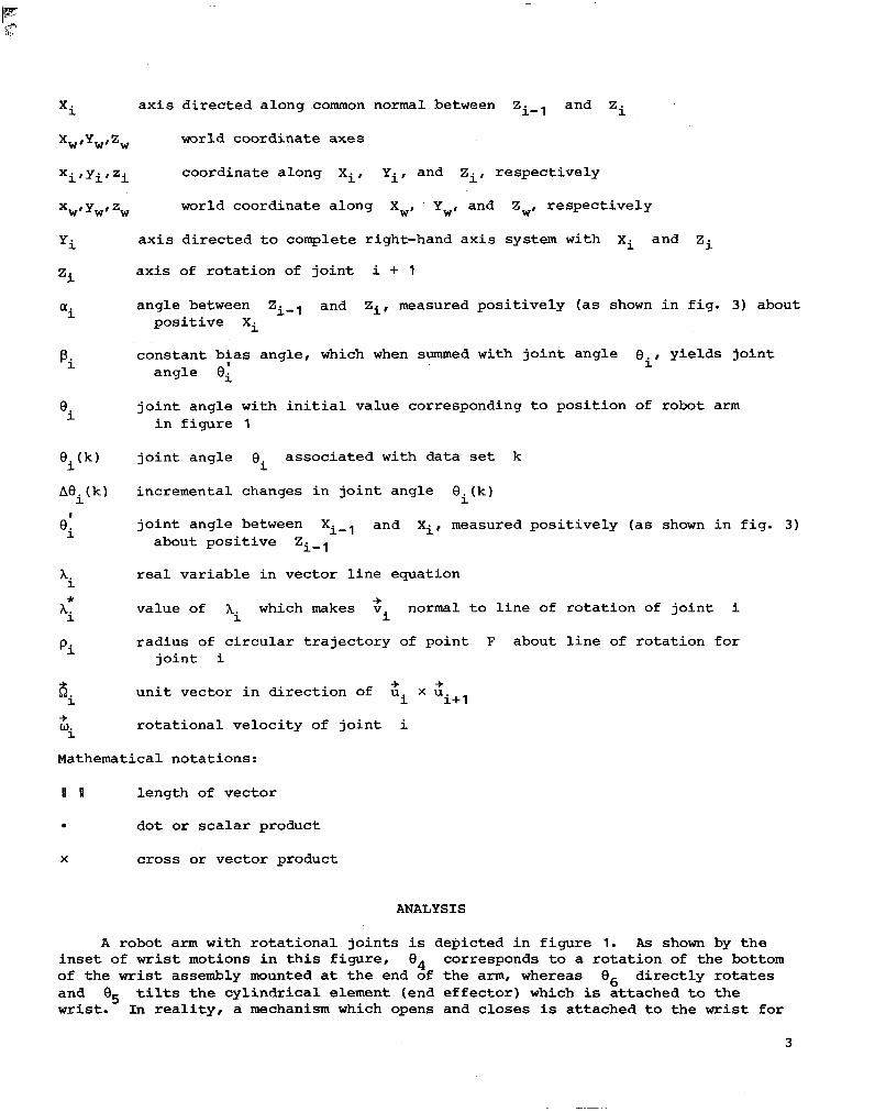
xi
Xw,Yw,Zw world coordinate axes
X i ' Y i ' Z i coordinate along xi, Yi, and Zi, respect ively
XWI Ywr zw world coordinate along X,, Y,, and Zw, respec t ive ly
'i
axis d i rec ted a long common normal between Zi-l and Zi
ax i s d i r ec t ed t o complete right-hand axis system with Xi and Zi
ax i s of ro t a t ion of j o i n t i + 1
'i angle between Zi-l and Zi, measured pos i t i ve ly (as shown i n f i g . 3) about pos i t i ve Xi
f'i constant bias angle, which when summed with joint angle Qi, y i e lds j o in t
angle ei
0 joint angle with ini t ia l value corresponding t o pos i t ion of robot arm i i n f i g u r e 1
€li (k ) joint angle associated with data set k
Aei(k) incremental changes in joint angle ei(k)
'i
I joint angle between Xi-l and Xi, measured pos i t i ve ly (as shown i n f i g . 3)
about posi t ive Zi-l
'i real var iab le in vec tor l ine equat ion
* 'i
value of Ai which makes v normal t o l i n e of ro ta t ion of j o i n t i -+ i
pi
8 un i t vec to r i n d i r ec t ion of u x u
%
rad ius of c i r cu la r t r a j ec to ry of poin t F about l ine of ro t a t ion fo r j o i n t i
+ + i i i+ 1
ro t a t iona l ve loc i ty of j o i n t i +
Mathematical notations:
II II length of vector
0 dot o r scalar product
X cross or vector product
ANALYSIS
A robot arm wi th ro t a t iona l j o in t s is depic ted in f igure 1. As shown by t h e i n s e t of w r i s t motions i n t h i s f i g u r e , B4 corresponds t o a ro t a t ion of t he bottom of the wrist assembly mounted a t t h e end of the arm, whereas 0, d i r e c t l y rotates and Q5 tilts the cyl indrical e lement (end effector) which is a t t a c h e d t o t h e w r i s t . I n r ea l i t y , a mechanism which opens and closes is at tached t o the wrist f o r
3

manipulating objects. The robot arm i n f igure 1 i s used f o r i l l u s t r a t i o n , b u t t h e subsequent development i s va l id fo r any geometric configuration of robot arm.
Suppose the exact location and or ien ta t ion of each j o i n t a x i s system of the robot arm i n f igure 1 are not known. The object ive i n t h i s a n a l y s i s i s t o develop a method t o determine the parameters which establ ish the geometr ic re la t ionships among t h e j o i n t a x i s systems for an assembled robot arm. !Chis object ive i s accomplished by moving the arm to d i f f e ren t pos i t i ons and making ce r t a in measurements, which a r e l a t e r used i n equations t o extract the desired parameters.
Measurements
Joint angle measurements.- As a point of reference for joint angle measurements, define = 0 (i = 1, 2 , ..., 6 ) f o r t h e i n i t i a l p o s i t i o n of the robot arm shown i n f i gu re 1. Thereaf ter , these joint angles are referenced to t h i s i n i t i a l z e r o posit ion.
'i
world coordinates.- The world reference axis system indicated i n f igure 2 is an a r b i t r a r i l y f i x e d a x i s system. For example, the o r ig in of t h i s a x i s system may be loca ted a t the corner of a f l a t t a b l e upon which the robot arm i s stationed, or the world a x i s system may correspond t o t h e a x i s system of a l a s e r t r a n s i t o r a camera. With respec t to t h i s world a x i s system, t h e rectangular coordinates (xw,yw, zw) of the point F i n f igure 2 are obtained. The point F i s loca ted a rb i t r a r i l y on some extension of the robot hand so t h a t when a rotat ion occurs , by varying a joint angle Bi, the point F w i l l move t o another position i n the world coordinate space. It i s not necessary to know the length or or ientat ion o f the extension.
The robot arm is moved t o d i f f e r e n t p o s i t i o n s by varying i t s joint angles . A t each new posi t ion, the joint angles Bi a r e ava i l ab le from sensors i n the robot arm i t s e l f , whereas the locat ion of point F i s ac tua l ly measured by using external measurement devices (sensors). It is assumed t h a t measurements of jo in t angles Bi and corresponding world coordinates of point F are avai lable €or the robot arm i n d i f fe ren t pos i t ions for th i s ana lys i s . Before proceeding, the axis systems t o be established are described.
J o i n t Axis Systems
Figure 3 i l l u s t r a t e s t h e a x i s systems associated wi th j o i n t s i and i + 1. By convention, joint i i s associated w i t h the coordinate system i - 1. Hence, j o i n t i corresponds to the axis system with o r i g i n a t Oi-l, whereas j o i n t i + 1 corresponds to t he o the r ax i s system wi th or ig in Oi. B y def in i t ion , the ax is of ro t a t ion fo r j o in t i always l ies a long the associated Zi-l. The vector gi i s t h e normal vector between Zi- and Zi, being directed toward Zi. The in te r - section point of ai w i t h Zi locates the or igin Oi. The a x i s Xi o r ig ina t e s from Oi i n the same d i r ec t ion a s 4 . In the event tha t Zi-l and Zi i n t e r s e c t ( f i g . 3( b) ), ai i s the zero vector, and Xi i s then directed from t h i s intersec- t i o n i n the d i rec t ion of the cross product obtained by+multiplying a u n i t vector along Zi-l by a u n i t vector along Zi. The vector r i s the vector from the
or igin Oi-, to the+in tersec t ion of ai w i t h Z i - 1 ( f i g . 3 ( a ) ) ; fo r i n t e r sec t ing l i n e s of rotat ion, r is a vector along Zi from oiml t o 0. ( f i g . 3 ( b ) ) . The angle ai is the angfe between a l i n e p a r a l l e l t o Zi-l througA the or igin Oi and Zi, being measured posi t ive about posi t ive Xi ( f i g . 3 ) . F ina l ly , t he j o in t
+
3.
i -*
4
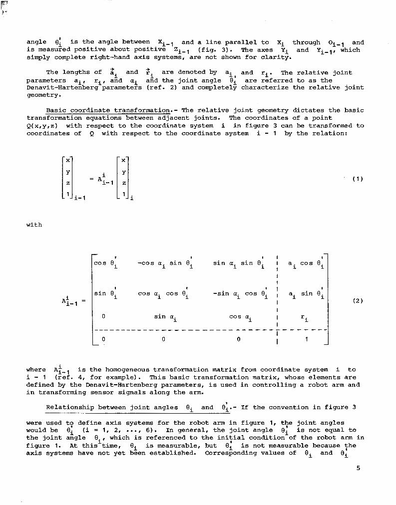
angle 8; is the angle between Xi-l and a l i n e paral le l t o Xi through oi-l and i s measured pos i t ive about pos i t ive Zi-l ( f i g . 3 ) . The axes yi and Y ~ - ~ , which simply complete right-hand axis systems, are not shown f o r c l a r i t y .
The lengths of a and r are denoted by ai, and ri. The r e l a t i v e j o i n t -+ -+ parameters ai, ri, and ai and the jo in t angle Bi a r e r e f e r r e d t o as the Denavit-Hartenberg parameters (ref. 2) and completely character ize the re la t ive joint geometry.
i i
Basic coordinate transformation.- The r e l a t i v e j o i n t geometry d ic ta tes the bas ic transformation equations between adjacent joints . The coordinates of a po in t Q(x,y,z) with respect to t he coo rd ina te system i i n f i g u r e 3 can be transformed t o coordinates
- . X
Y
z
1 - .
with
- ~
of Q with respect to the coordinate system i - 1 by the r e l a t ion :
i- 1 1 1.
A i - 1 =
i
1 1 1
-cos a s i n 8 i i
I I
I
s i n ei cos a cos 8 -s in a cos 8 i i i
I o s i n a i
Lo 0 0 I
where A i - l i s t h e homogeneous transformation matrix from coordinate system i t o i - 1 ( r e f . 4, f o r example). This basic transformation matrix, whose elements are defined by the Denavit-Hartenberg parameters, i s used i n c o n t r o l l i n g a robot arm and i n transforming sensor signals along the arm.
Relationship between jo in t ang le s Bi and e;.- I f the convent ion in f igure 3
were used t y define axis systems for the robot arm i n f i g u r e 1, t!e jo in t ang le s would be Oi (i = 1, 2, ..., 6). In general , the joint angle ei is not equa l to t he j o in t ang le Oi, which is r e f e r e n c e d t o t h e i n i t i a l c o n d i t i o n of the robot arm i n f igu re 1. A t t h i s time, ei is measurable, but 8; i s not measurable because :he a x i s systems have not yet been established. Corresponding values of Oi and Oi
5
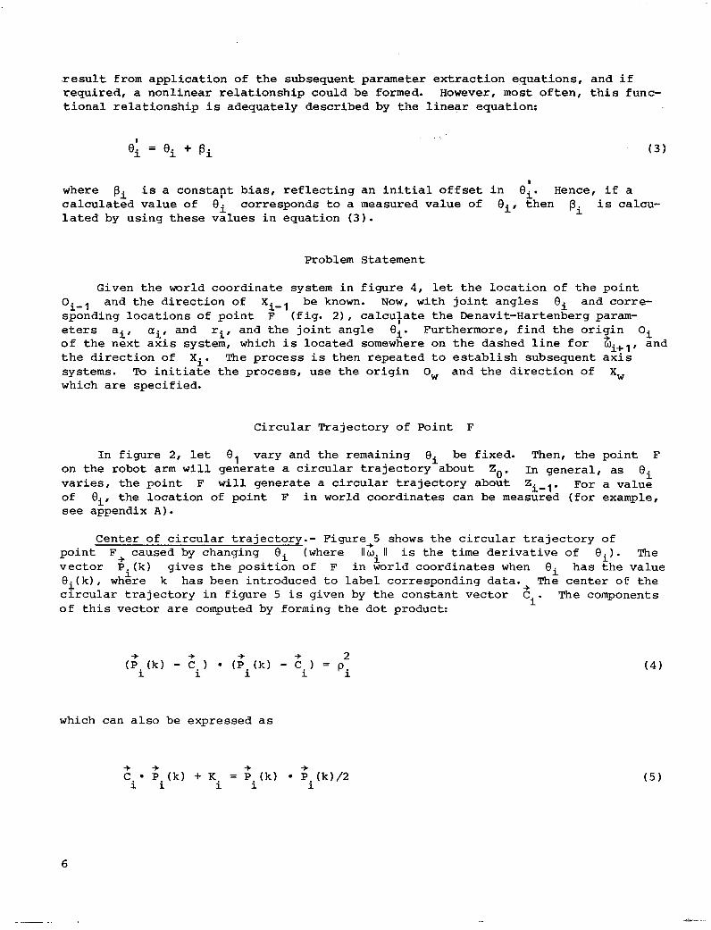
r e s u l t from appl ica t ion of the subsequent parameter extraction equations, and i f required, a nonl inear re la t ionship could be formed. However, most o f t e n , t h i s func- t i o n a l r e l a t i o n s h i p is adequately described by the l inear equat ion:
I ei = ei + pi
I where pi is a cons t ap t b i a s , r e f l ec t ing an i n i t i a l o f f se t i n €Ii. Hence, i f a calculated value of fIi corresponds t o a measured value of Oi, then pi i s calcu- l a t e d by using these values in equat ion ( 3 ) .
Problem Statement
Given t h e world coordinate system i n f i gu re 4, l e t t he l oca t ion of t he po in t
O i - 1 and the d i r ec t ion of Xi-l be known. Now, wi th jo in t angles Bi and corre- sponding locations of po in t F ( f ig . 21, calcufate the Denavit-Hartenberg param- eters ai, ai, and ri, and the j o in t ang le ei. Fur thermore , f ind the o r i in Oi of the next ax is system, which i s located somewhere on t h e dashed l i n e f o r wit,, and t h e d i r e c t i o n of Xi. The process i s then repeated to es tabl ish subsequent axis systems. To i n i t i a t e t he p rocess , u se t he o r ig in Ow and the d i r ec t ion of X, which a re spec i f ied .
9
Circular Trajectory of Point F
In f igure 2, l e t 8 , vary and the remaining Qi be fixed. Then, the po in t F on the robot a r m w i l l generate a c i rcu lar t ra jec tory about Zo . In general , as Qi
v a r i e s , t he po in t F w i l l generate a c i rcu lar t ra jec tory about Zi-l. For a value of Qi, the locat ion of point F i n world coordinates can be measured ( f o r example, see appendix A).
Center of c i r cu la r t r a j ec to ry . - Figure+5 shows t h e c i r c u l a r t r a j e c t o r y of po in t F. caused by changing 8 ; (where lIwl II i s the t i m e der ivat ive of 8 , ) . The vec tor pfi(k) g ives the posi t iGn of F i n world coordinates when Bi has ;he value O i ( k ) , where k has been introduced to label corresponding data.+ The center of t he c i r c u l a r t r a j e c t o r y i n f i g u r e 5 i s given by the constant vector Ci. The components
l.
of t h i s v e c t o r a r e computed by forming the dot product:
which can a l s o be expressed a s
6

where
Ki = -pi ci - q 2 -%
is a constant.
Equation (5) represents k linear equations in four unknowns: Ki and the three components of the vector Ci. Four different position vectors (si (k) , -%
k = 1, 2, 3, and 4) are sufficient to provide enough equations for the solution of these constants. Thus, a robot arm with 6 rotational joints would require 24 position measurements ( 4 for each of the 6 joints). Each position vector is made up of three components, representing a point in the world coordinate system (X~,Y~,Z~). In actual situations, where sensor errors are present, more measurements will be needed to allow least-squares estimates of the constants.
Once the vector 8 and the scalar Ki are found, the radius of the circle is given by equation (6), written as i
TJnit vector u .- Figure 6 shows the circular trajectory of point F and two -%
i position vectors Zi(k) and Pi(k+l) , along with the incremental Joint angle 3.
between these position vectors. A unit vector normal to the plane of the circular trajectory a2d passing through point Ci (whose coordinates are the components of the vector C. ) is
1
7
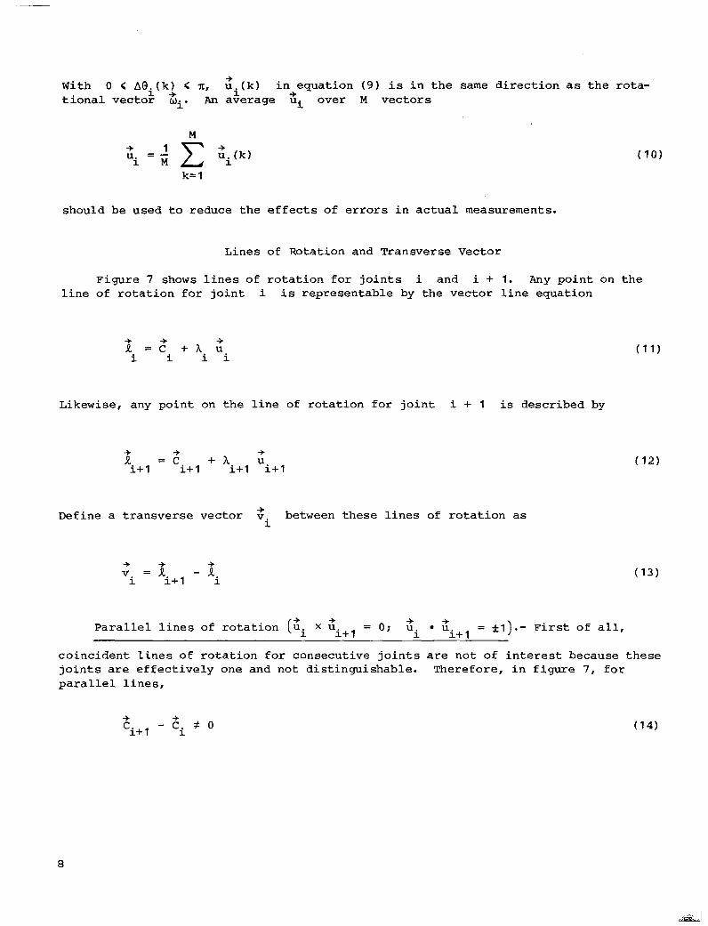
With 0 < dei( k ) < n, zi( k) in equat ion ( 9 ) is i n t h e same d i r ec t ion as the ro ta - ' t i o n a l v e c t o r mi. An average ui over M vec tors -+ -+
M
k= 1
should be used t o reduce the effects of errors i n a c t u a l measurements.
L i n e s of Rotation and Transverse Vector
Figure 7 shows l i n e s of r o t a t i o n f o r j o i n t s i and i + 1. Any poin t on t h e l i n e of r o t a t i o n f o r j o i n t i is representable by the vector l ine equat ion
Likewise, any poin t on t h e l i n e of r o t a t i o n f o r j o i n t i + 1 is described by
a = c + ? l u i+ 1 i+ 1 i + l i + l
Define a t ransverse vector v between these l i nes of ro t a t ion as + i
+ -+ v = R - 1
+ i i+ 1 i
P a r a l l e l l i n e s of ro t a t ion (ui X u + + + + = o ; u . U i+ 1 i i+ 1
= * l ) . - First of a l l ,
co inc iden t l i nes of ro ta t ion for consecut ive jo in ts a re no t of interest because these j o i n t s a r e e f f e c t i v e l y one and not dist inguishable. Therefore, in f igure 7, f o r p a r a l l e l l i n e s ,
+ + ci+l - ci f 0
a
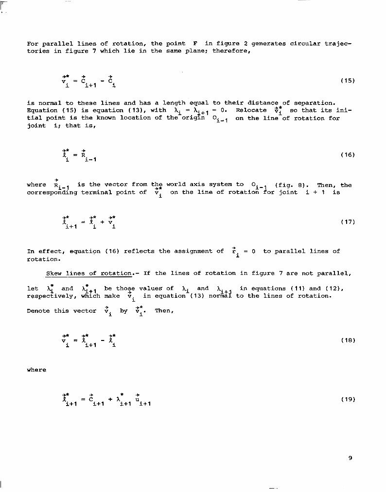
For parallel lines of rotation, the point F in figure 2 generates circular trajec- tories in figure 7 which lie in the same plane; therefore,
-+* + -+ v = c -c i i+ 1 i
is normal to these lines and has a length equal to their distance of separation. Equation ( 15) is equation ( 13), with Ai = Ai+l = 0. Relocate 3; so that its ini- tial point is the known location of the origm oi-l on the line of rotation for joint i; that is,
+* + 2, = R 1 i- 1
where is the vector from the world axis system to +* oi-l (fig. 8). Then, the corresponding terminal point of v on the line of rotation for joint i + 1 is i
+ Ri- 1
I* = 2 . + v +* +* i+ 1 1 i
In effect, equation (16) reflects the assignment of r = 0 to parallel lines of rotation.
+ i
- Skew lines of rotation.- If the lines of rotation in figure 7 are not parallel,
let and g+l be those values of hi and in equations ( 11) and ( 12), respectively, which make v in equation (13) norma? to the lines of rotation. + Ai +
i
Denote this vector v by vi. Then, + +* i
+* +* +*
where
+* R = c + A u
+ * + i+ 1 i+ 1 i+l i+l
9

and
+* + * + R = c + A * u i i 1 i
are the intersection points
v two orthogonality conditions are +* i'
of v with the lines of rotation. By definition of +* i
v * U = o +* + i i
and
v * U +* + = o i i+ 1
Equations (21) and (22) can be solved simultaneously for the scalar values AT and
g+l to get
and
where, for skewed lines, + + (ui+ 1 i * U ) # 1.
10
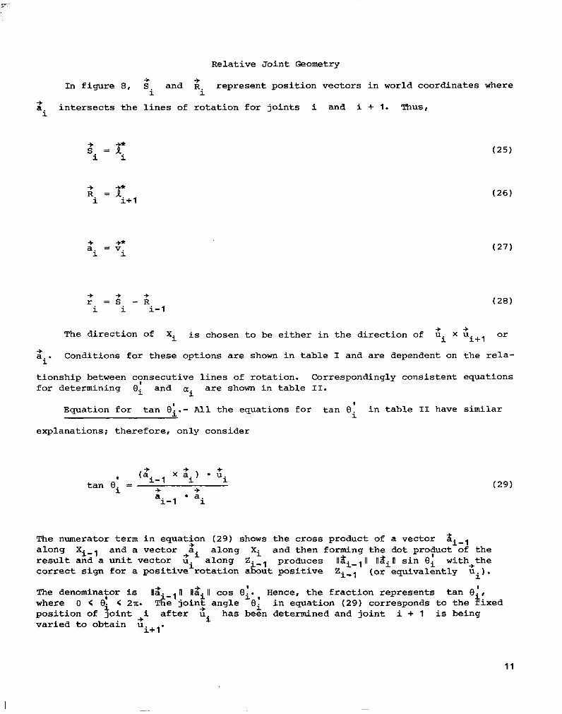
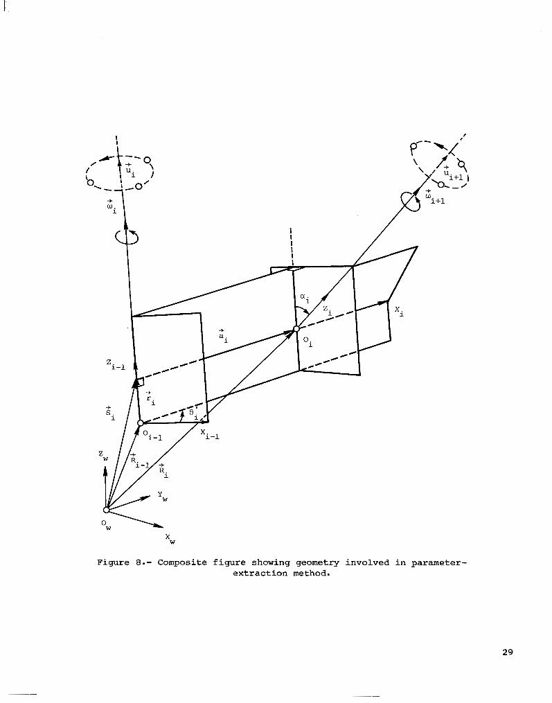
Relat ive Joint Geometry
In figure 8, and R represent pos i t ion vec tors in world coordinates where +
i i + a i n t e r s e c t s t h e l i n e s of r o t a t i o n f o r j o i n t s i and i + 1. Thus, i
s ' = R +*
i i
R = A + +* i i+ 1
-b +* i i a = v
-b -b -b
The d i r ec t ion of Xi is chosen t o be e i t h e r i n t h e d i r e c t i o n of ui X u o r + + i + l
+ a . Conditions for these options are shown i n table I and are dependent on the r e l a -
t ionship between consecutive l ines of rotation. Correspondingly consistent equations for determining 0; and a r e shown i n t a b l e 11.
i
'i I
Equation for tan el. - All the equat ions for tan Eli i n t a b l e I1 have similar
explanations; therefore, only consider
The numerator t e r m in equation (29) shows the cross product of a vector si-l along Xi- and a vector a. along Xi and then forming the dot protuct of the resul t and a un i t vec to r ui along Zi-l produces lldi-,Il I18iII s i n Oi with+the correct sign f o r a pos i t ive ro ta t ion about pos i t ive Zi-l (or equivalently ui) .
The denomina:or is Ilai,l II llai II cos 0;. , Hence, the f rac t ion represents t an e!, where 0 < Oi < 2n. The jo in t ang le Oi in equation (29) corresponds to the f ixed pos i t ion of j o i n t i a f t e r u has been determined and joint i + 1 is being var ied t o obtain u
+ + 1
+ +
-+ + i
i+1'
11
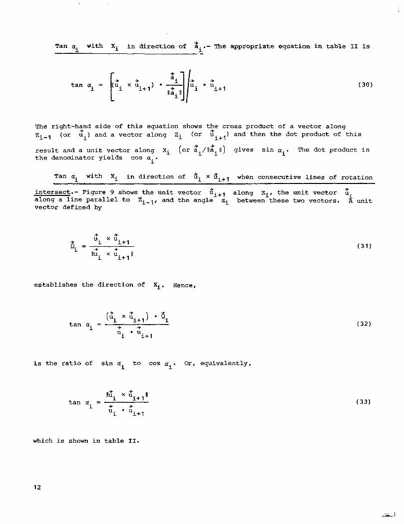
Tan a with Xi i n d i r e c t i o n of a .- The appropriate equation in table 11 is + i .. . - i
The right-hand side of this equat ion shows the cross product of a vector along Zi-, (or u . ) and a vector along Zi (of ui+l) and then the dot product of t h i s
r e s u l t and a unit vector along X i (o r 2i/ll;i 11) g ives s in a . The dot product in t h e denominator yields cos a . i
+ 4.
1
i
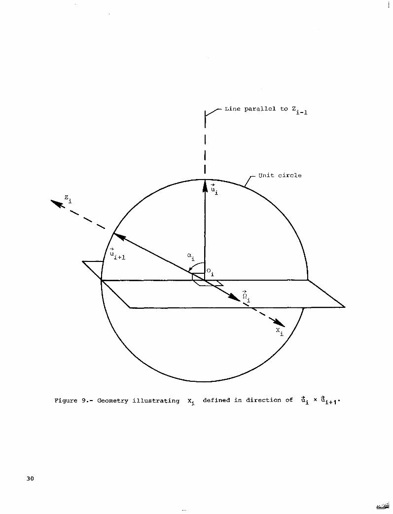
Tan ai with Xi i n d i r e c t i o n of ?ii x when consecutive l ines of ro t a t ion
intersect.- Figure 9 shows the un i t vec tor ui+l along zit the un i t vec tor u along a l i n e p a r a l l e l t o Zi,,, and the angle ai between these t w o vectors. A u n i t vector defined by
+ + i
u x u i i + l
Ilu x u II i i+ 1
6 i = + -f
es tab l i shes the d i rec t ion of Xi. Hence,
+ i+ 1
i i+l
t a n a = i u * U + +
i s t h e r a t i o of s i n a t o COS a . O r , equivalent ly , i i
llUi x z II + t a n a =
i+ 1
i i+ 1 i 4. + u * U
which is shown i n t a b l e 11.
12
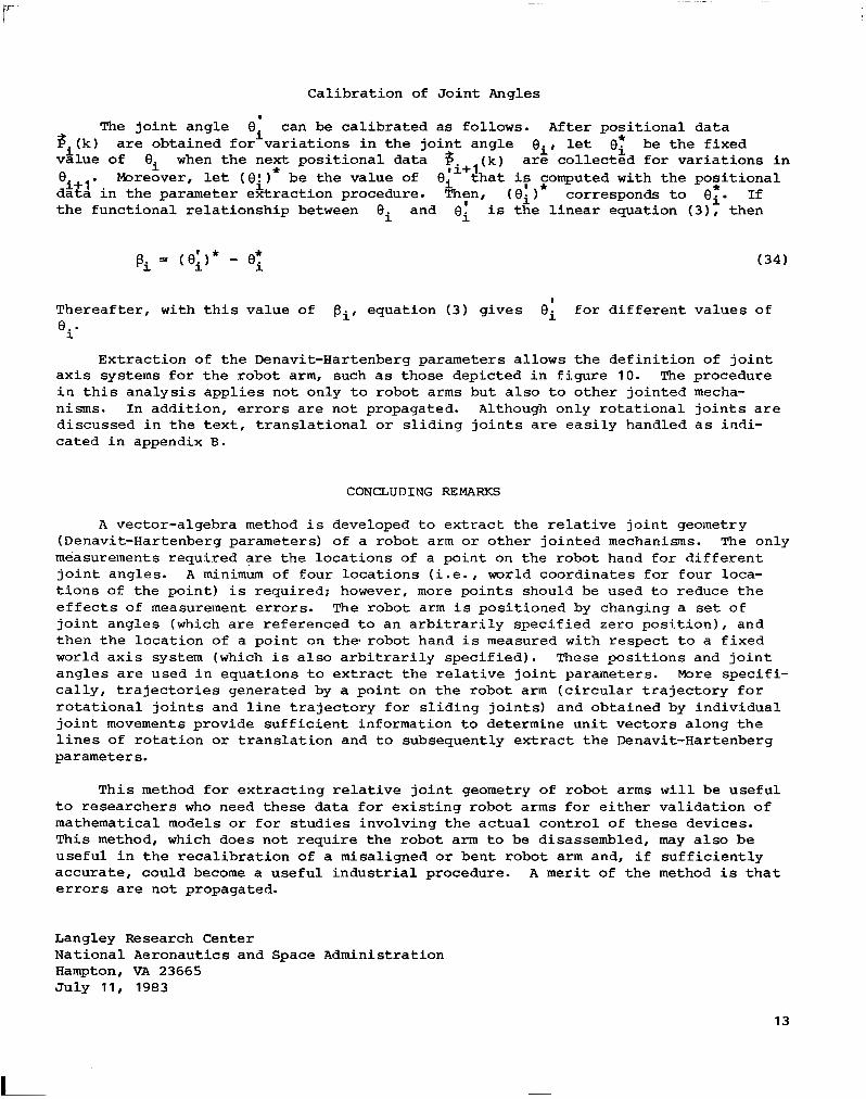
Calibrat ion of J o i n t Angles
I
The joint angle can be ca l ibra ted as follows. After posit ional data 'i 3. (k) are obta ined for var ia t ions in the jo in t angle Bi I l e t 0; be the f ixed
v h u e of ei when the next pos i t iona l da ta
'i+ 1 d a t a i n t h e parameter extraction procedure. Then, (e i ) corresponds t o ei. I f the func t iona l re la t ionship between ei and 0; i s the l inear equat ion ( 3 ) I then
ti+ 1 ('1 a r e c o l l e c t e d f o r v a r i a t i o n s i n . Moreover, l e t (e:)* be the value of €Ii t h a t if gomputed with the posi t ional *
Thereafter, with this value of pi, equation ( 3 ) gives e; for different values of 0: -
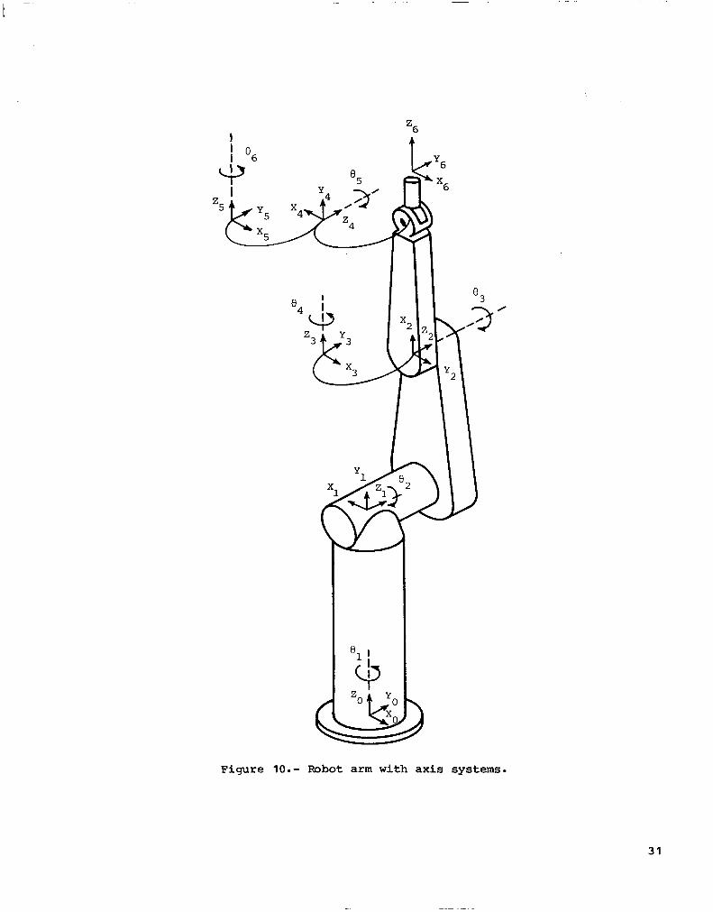
Extraction of the Denavit-Hartenberg parameters allows the definition of joint ax i s systems for the robot arm, such as those depic ted in f igure 10. The procedure in t h i s ana lys i s app l i e s no t on ly t o robo t arms bu t a l so t o o ther jo in ted mecha- nisms. In addition, errors are not propagated. Although on ly ro t a t iona l j o in t s a r e d i scussed i n t he t ex t , t r ans l a t iona l o r s l i d ing j o in t s are easi ly handled as indi- c a t e d i n appendix B.
CONCLUDING REMARKS
A vector-algebra method i s developed t o e x t r a c t t h e r e l a t i v e j o i n t geometry (Denavit-Hartenberg parameters) of a robot arm o r o the r j o in t ed mechanisms. The only measurements requi red a re the loca t ions of a po in t on the robot hand €o r d i f f e ren t j o i n t angles. A minimum of four locat ions ( i . e . , world coordinates for four loca- t i o n s of t he po in t ) is required; however, more points should be used t o reduce the e f f e c t s of measurement e r ro r s . The robot arm i s posi t ioned by changing a set of j o in t ang le s (which a re re fe renced to an a rb i t ra r i ly spec i f ied zero pos i t ion) , and then the locat ion of a po in t on the. robot hand i s measured wi th respec t to a f ixed world a x i s system (which i s a l s o a r b i t r a r i l y s p e c i f i e d ) . These pos i t ions and j o i n t angles are used in equa t ions t o ex t r ac t t he r e l a t ive j o in t pa rame te r s . More specif i - ca l ly , t ra jec tor ies genera ted by a poin t on the robot arm ( c i r c u l a r t r a j e c t o r y f o r r o t a t i o n a l j o i n t s and l i n e t r a j e c t o r y f o r s l i d i n g j o i n t s ) and obtained by individual j o i n t movements provide sufficient information to determine unit vectors along the l i n e s o f r o t a t i o n o r t r a n s l a t i o n and t o subsequently extract the Denavit-Hartenberg parameters.
This method f o r e x t r a c t i n g r e l a t i v e j o i n t geometry of robot arms w i l l be useful t o r e s e a r c h e r s who need these data for exis t ing robot arms fo r e i t he r va l ida t ion o f mathematical models or for s tudies involving the actual control of these devices . This method, which does not require the robot arm t o be disassembled, may a l so be u s e f u l i n t h e r e c a l i b r a t i o n of a misaligned or bent robot arm and, i f s u f f i c i e n t l y accurate, could become a useful industrial procedure. A merit of t he method i s t h a t e r r o r s are not propagated.
Langley Research Center National Aeronautics and Space Administration Hampton, VA 23665 Ju ly 11, 1983
13
APPENDIX A
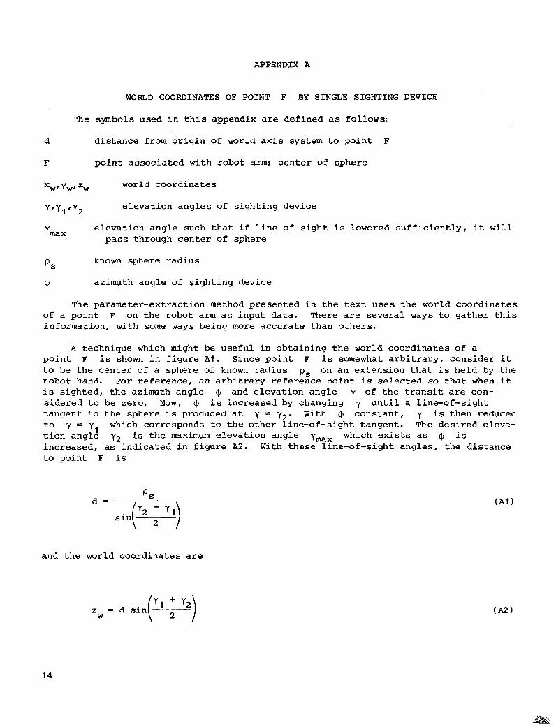
WORLD COORDINATES OF POINT F BY SINGLE SIGHTING DEVICE
The symbols used i n t h i s appendix a re def ined as follows:
d dis tance from origin of world a x i s system t o poin t F
F point associated with robot arm; center of sphere
world coordinates
Y,Yl 'Y2 elevation angles of sighting device
Y m X e levat ion angle such t h a t i f l i n e of s igh t i s lowered s u f f i c i e n t l y , it w i l l
pass through center of sphere
P S
J , azimuth angle of sighting device
known sphere radius
The parameter-extraction method presented i n t h e t e x t u s e s t h e world coordinates of a po in t F on the robot arm as input data. There are several ways t o g a t h e r t h i s information, with some ways being more accurate than others.
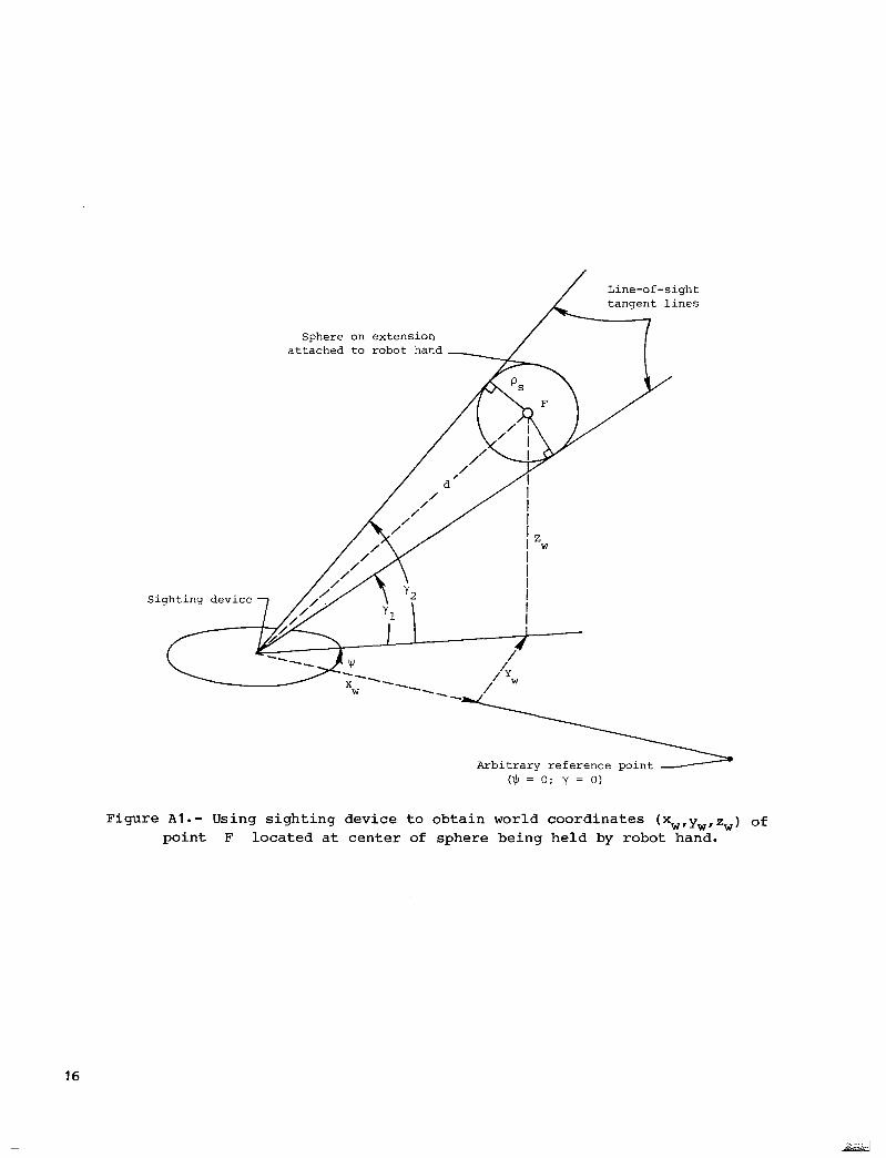
A technique which might be usefu l in ob ta in ing the world coordinates of a po in t F i s shown i n f i g u r e A l . Since point F is somewhat a rb i t ra ry , cons ider it t o be the center of a sphere of known rad ius ps on an extension that is held by t h e robot hand. For reference, an arbitrary reference point i s selected so t h a t when it i s sighted, the azimuth angle (1, and elevat ion angle y of t h e t r a n s i t are con- s ide red t o be zero. N o w , 3, i s increased by changing y u n t i l a l ine-of-sight tangent to the sphere i s produced a t y = y2. With 4 constant , y i s then reduced t o y = y1 which corresponds to the other l ine-of-s ight tangent . The desired eleva- t ion angle y2 is the maximum elevation angle ymax which e x i s t s as (1, is increased, as ind ica t ed i n f i gu re A2. With these l ine-of-sight angles, the distance t o poin t F is
and the world coord ina tes a re
14
APPENDIX A
YW = d cos(” + y2 ) s i n J,
x W = d COS^' + y2 ) COS 3,
N o measurements were made to ascertain the accuracy of t h i s measurement technique.
15
l i
Line-of-sight tangent lines
Sphere on extension attached to robot hand
Sighting device
Arbitrary reference point ($ = 0 ; y = 0 )
Figure A l e - Using sighting device to obtain world coordinates ( x w I y w I z w ) of point F l oca t ed a t cen te r of sphere being held by robot hand.
16

Line-of-sight tangent lines
Circumferential surface of sphere
Sighting device
(l) = 0; y = 0)
Figure A2.- I l l u s t r a t i o n of maximum elevat ion angle for l ine-of-s ight tangent l i n e to spherical surface.
17

APPENDIX B
RELATIVE J O I N T GEOMETRY FOR SLIDING JOINTS
In the text, primary emphasis i s placed on r o t a t i o n a l j o i n t s ; however, t h e same basic analysis holds for Pl iding joints (extendable segments) . L e t r be t h e extension variable and €Ii+! be a cons t an t fo r j o in t i + 1 i n t h e rogot arm. Measuring locations of a p o m t F on the robot arm f o r two dif fa ren t ex tens ions
(‘i+ 1
+ i 1
(k) , where k = 1 and 2 ) gives two po in t s on a l i n e . L e t Pi+l (1 1 correspond
t o the extension r = r ( 1 ) and ( 2 ) correspond t o + r + = r (21 , where
‘lri+ 1
-+ -+ i+ 1 i+ 1 i+ 1 i+ 1
-+ ( 2 ) II > Ilri+l ( 1 ) 11. Then, ins tead of the un i t vec tor in equa t ion (9), t h e u n i t -+
vector i s
Furthermore, instead of the l ine equation (121 , t he new l ine equat ion i s
-+ + i+ 1
The remaining steps in the parameter extraction are the same a s i n t h e t e x t .
The l i n e of extension represented by equation ( B 2 ) can be s h i f t e d , i f d e s i r e d , t o p a s s through some chosen point ; for example, the Pi+l( l ) in the equat ion can be
replaced by Ri-,. This makes the ai terms in equation ( 2 ) equal t o z e r o f o r s l i d -
i n g j o i n t s ( r e f . 5).
-+
+
18

REFERENCES
1. Meintel, Alfred J. , Jr .; and Larsen, Ronald L. : NASA Research in Te leope ra t ion and Robotics. Paper presented a t Society of Photo-Optical Instrumentation Engineers conference (San Diego, Ca l i fo rn ia ) , Aug. 23-27, 1982.
2. Whitney, Daniel E.: Resolved Motion Rate Control of Manipulators and Human Prostheses. IEEE Trans. Man-Mach. sys . , vol . MMS-IO, no. 2, June 1969, pp. 47-53.
3. Denavit, J.; and Hartenberg, R. S.: A Kinematic Notation for Lower-Pair Mechanisms Based on Matrices. J. Appl. Mech., vol. 22, no. 2, June 1955, pp. 215-221.
4. Yeh, Shao-Chi: Locomotion of a Three-Legged Robot Over S t ruc tu ra l Beams. M.S. Thesis, The Ohio State Univ., Aug. 1981.
5. Paul, Richard P.: Robot Manipulators: Mathematics, Programming, and Control - The Computer cont ro l of Robot Manipulators. MIT Press, 1982.
19
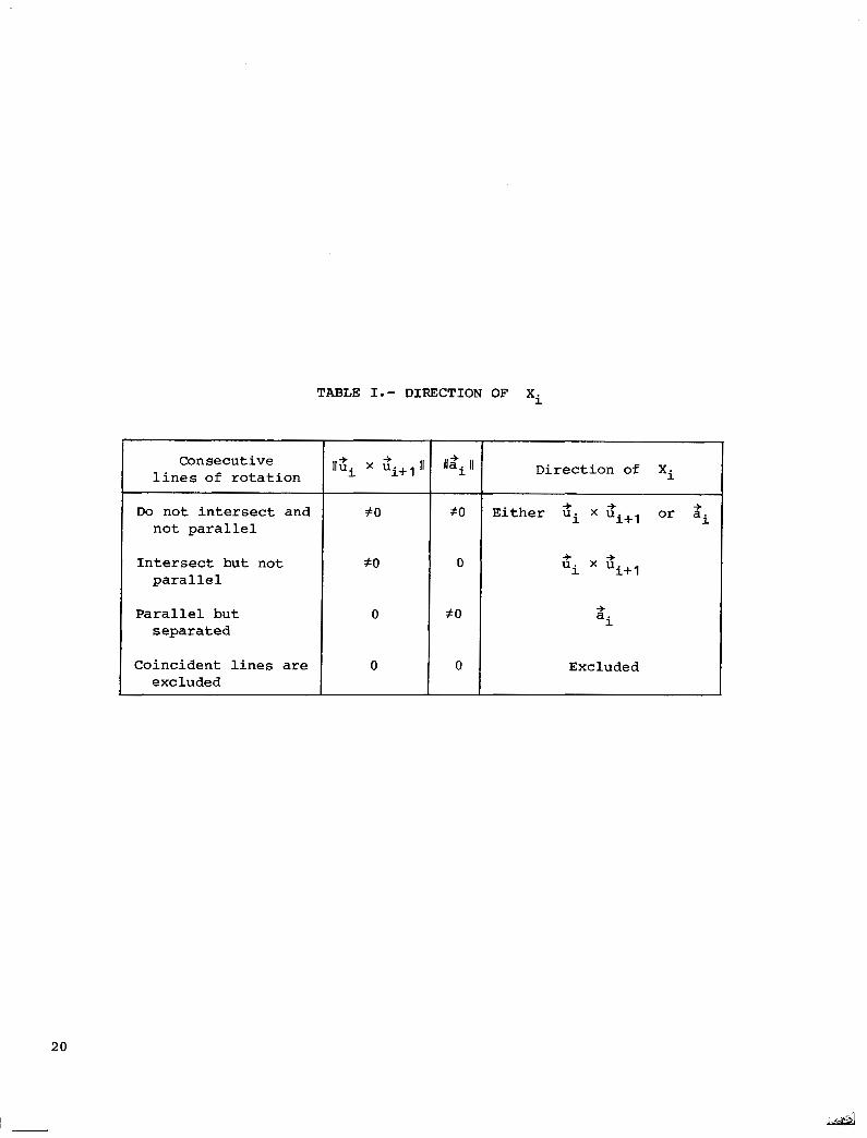
TABLE I. - DIRECTION OF Xi
Consecutive lines of rotation
Do not intersect and not parallel
Intersect but not parallel
Parallel but separated
Coincident lines are excluded
f O
20
0
0
Ila I1 +
20
0
20
0
Direction of xi
+ + + Either ui x ui+l or ai
+ a i
Excluded
20

1 Direction ~ of current
I' xi
I
TABLE 11.- CONSISTENT TANGENT EQUATIONS FOR ai AND ei
Previously defined direction of Xi-l
U + +
x u i-1 i
+ + Ilu. x ui+l II 1 tan a = + i u m u
+ i i + l
+ tan a. 1 = [It x ui+l) -+ 8 dl+ u * U +
II a . II i i+l 1
+ a i- 1
+ + Ilu. x u II 1 i+l
i i+ l
tan a = + i u * U +
+ + + u . U i+ 1 i i+l

I I
Wrist notions
/ d- Wrist
Figure 1.- Robot arm with rotational joints. Initial position.
22

Measurement point
Deflected extension attached t o robot
end e f f ec to r
I e 3
/
, 0 3'
e ' G3
I
World reference
Figure 2.- World axis system and robot arm with extension for measurements.
23

1-1 X. 1-1
( a ) Nonintersect ing l ines of ro ta t ion .
(b) In te rsec t ing l ines of ro t a t ion .
Figure 3. - Consecutive joint axis systems and relative joint geometry.
24
, I,-

\ \
\ \ \ \ \ \
I I
&i+1
I I
I I
I I
I I '
Figure 4.- I l l u s t r a t i o n of world a x i s System, vector Ri-l, and direct ion of Xi-l +
f o r problem statement. Dashed l i nes r ep resen t unknown l i n e s of ro t a t ion for consecutive joints.
25
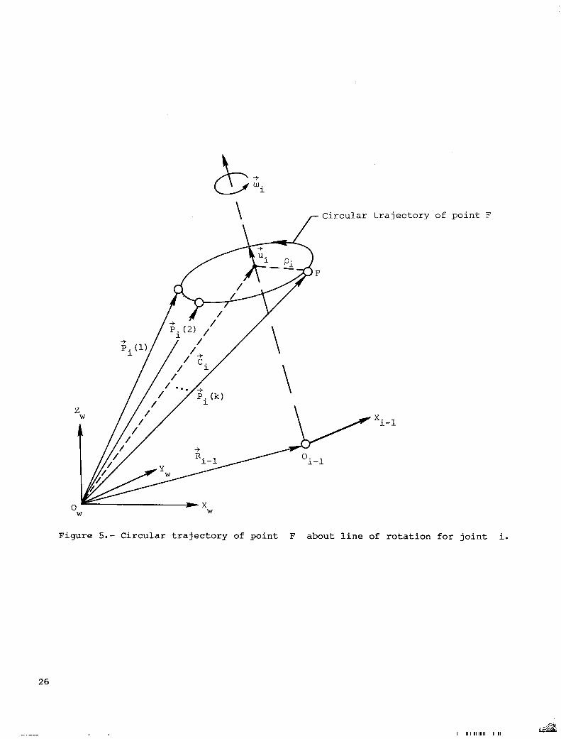
trajectory of point F
X i-1
Figure 5.- Circular trajectory of point F about line of rotation for joint i.
26
"_ I II I 111 I I II I I I

X i-1
Figure 6.- Un i t vector i n same direct ion as joint rotat ional vector .
27

\ \
\ \
Figure 7.- Lines of rotation €or consecutive joints and transverse vector.
28
I:
Figure 8.- Composite figure showing geometry involved in parameter- extraction method.
29
Line paral le l t o Z i-1
,- u n i t circle
Figure 9. - Geometry i l l u s t r a t i n g xi defined i n d i r e c t i o n Of h i X Qi+l
30
. ..
Figure 10. - -bot arm with axis systems.
31

1. Report No. 2. Government Accession No.
NASA TP-2191 4. Title and Subtitle
VECTOR-ALGEBRA APPROACH TO EXTRACT DENAVIT-HARTENBERG PARAMETERS OF ASSEMBLED ROBOT ARMS
7. Author(s)
~ L. Keith Barker -
9. Performing Organization Name and Address - NASA Langley Research Center Hampton, VA 23665 -
12. Sponsoring Agency Name and Address
National Aeronautics and Space Administration Washington, DC 20546
15. Supplementary Notes
3. Recipient’s Catalog No.
C R e p o n Date
Auaust 1983 6. Performing Organization Cocb
506-54-63-01-00 8. Performing Organization Report No.
615621 10. Work Unit No.
11. Contract or Grant No.
13. Type of Report and Period &wered
Technical Paper 14. Sponsoring Agency Code
16. Abstract I The Denavit-Hartenberg parameters characterize the joint axis systems in a robot arm and, naturally, appear in the transformation matrices from one joint axis system to another. These parameters are needed in the control of robot arms and in the passage of sensor information along the arm. This paper presents a vector-algebra method to determine these parameters for any assembled robot arm. The idea is to measure the location of the robot hand (or extension) for different joint angles and then use these measurements to calculate the parameters.
17. Key Words (Suggested by Author(s1) 18. Distribution Statement
Robot arm Manipulator
Unclassified - Unlimited
Joint axis systems Denavit-Hartenberg parameters
Relative joint geometry Subject Category 64 Parameter extraction
19. Security Classif. (of this report) 20. Security Classif. (of this page) ~~
21. No. of Pages 22. Rice
rhclassified A03 32 Unclassified ~
For sale by the National Technical Information Service, Springfield, Virginia 22161 NASA-Langley, 1983
![Robot Dynamics & Control - University of Queenslandrobotics.itee.uq.edu.au/~metr4202/2013/lectures/L4-Dynamics.v1.pdf · 4 16-Aug Robot Dynamics & Control ... Denavit Hartenberg [DH]](https://img.pdfslide.net/doc/110x75/5a8794817f8b9a882e8dbf53/robot-dynamics-control-university-of-metr42022013lecturesl4-dynamicsv1pdf4.jpg)


![AUTOMATED NON-DESTRUCTIVE EXAMINATION OF … · (Denavit–Hartenberg) kinematic coefficients for the robot and additional degrees of freedom [Ref 4] Figure 4: Typical robotic NDE](https://img.pdfslide.net/doc/110x75/5bdf515f09d3f251108b56df/automated-non-destructive-examination-of-denavithartenberg-kinematic-coefficients.jpg)