Embed Size (px)
Citation preview
Abstract—Fine alignment of main ship power plants mechanisms
and shaft lines provides long-term and failure-free performance of
propulsion system while fast and high-quality installation of
mechanisms and shaft lines decreases common labor intensity. For
checking shaft line allowed stress and setting its alignment it is
required to perform calculations considering various stages of life
cycle. In 2012 JSC SSTC developed special software complex
“Shaftline” for calculation of alignment of having its own I/O
interface and display of shaft line 3D model. Alignment of shaft line
as per bearing loads is rather labor-intensive procedure. In order to
decrease its duration, JSC SSTC developed automated alignment
system from ship power plants mechanisms. System operation
principle is based on automatic simulation of design load on bearings.
Initial data for shaft line alignment can be exported to automated
alignment system from PC “Shaft line”.
Keywords—ANSYS, propultion shaft, shaftline alignment, ship
power plants.
I. INTRODUCTION
RECISE alignment of main mechanisms of ship power
plants and shaft lines provides long and trouble-free
operation of ship propulsion system while fast and high-
quality installation of mechanisms and shaft lines onboard the
ship reduces its overall labor intensity.
Calculation of alignment parameters is essential part of
documentation developed in course of ship construction.
Loads on bearings, tensions in shaft lines and deflection
curves defined by calculations directly affect operation
reliability of ship propulsion system. Such calculations are
mainly performed by special software. This software is used
by many classification societies [1] as well as by companies
specializing in manufacturing and construction of propulsion
systems [2].
In order to calculate alignment parameters of ship shaft
lines, JSC SSTC has developed special software
“Valoprovod” with integrated I/O interface, and display of
shaft line 3D model. Calculation module functions are
performed by ANSYS [3], [4] complex using general finite
elements analysis method and having wide capabilities in
structural analysis. This program is able to generate shaft line
of almost any complexity upon availability of comprehensive
data regarding its loads and geometrical parameters.
A. O. Mikhailov is with the Shipbuilding& Shiprepair Technology Center, Saint-Petersburg 198095 Russia (e-mail: [email protected]).
K. N. Morozov is with the Shipbuilding& Shiprepair Technology Center,
Saint-Petersburg 198095 Russia (e-mail: [email protected]).
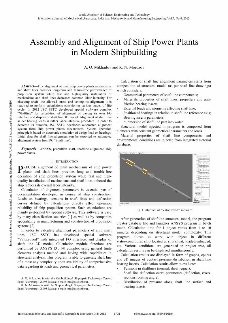
Calculation of shaft line alignment parameters starts from
composition of structural model (as per shaft line drawings)
which considers:
- Geometrical parameters of shaft line components;
- Materials properties of shaft lines, propellers and anti-
friction bearing inserts;
- External loads and moments affecting shaft line;
- Position of bearings in relation to shaft line reference axis;
- Bearing inserts parameters;
- Submersion of shaft line part into water
Structural model injected in program is composed from
elements with constant geometrical parameters and loads.
Material properties of shaft line components and
environmental conditions are injected from integrated material
database.
Fig. 1 Interface of “Valoprovod” software
After generation of shaftline structural model, the program
creates database file and launches ANSYS program in batch
mode. Calculation time for 1 object varies from 1 to 10
minutes depending on structural model complexity. This
program allows to work with object in different
states/conditions: ship located at slip/afloat, loaded/unloaded,
etc. Various conditions are generated in project tree, all
calculation results can be displayed simultaneously.
Calculation results are displayed in form of graphs, epures
and 3D images of contact pressure distribution in shaft line
bearing inserts. Calculation results allow to evaluate:
- Tensions in shaftlines (normal, shear, equal);
- Shaft line deflection curve parameters (deflection, cross-
sections rotating angle),
- Distribution of pressure along shaft line surface and
bearing inserts.
Assembly and Alignment of Ship Power Plants
in Modern Shipbuilding
A. O. Mikhailov and K. N. Morozov
P
World Academy of Science, Engineering and TechnologyInternational Journal of Mechanical, Aerospace, Industrial, Mechatronic and Manufacturing Engineering Vol:7, No:8, 2013
1702International Scholarly and Scientific Research & Innovation 7(8) 2013 scholar.waset.org/1999.8/16194
Inte
rnat
iona
l Sci
ence
Ind
ex, I
ndus
tria
l and
Man
ufac
turi
ng E
ngin
eeri
ng V
ol:7
, No:
8, 2
013
was
et.o
rg/P
ublic
atio
n/16
194
In case extra depth of analysis is required, one can open
project file directly in ANSYS.
Upon analysis of calculation results, the alignment
parameters get optimized. This is aimed to:
- Meet requirements of suppliers of bearings, gearboxes
and main propulsion units regarding their alignment and
assembly;
- Achieve optimal tensions in shaft lines;
- Achieve equal distribution of contact pressures in shaft
line bearing inserts.
The optimization is performed by changing position of shaft
line supports.
This program can automatically optimize contact pressures
in shaft line bearing inserts. After operation mode startup,
bearings rotate automatically in accordance with natural shaft
line curve.
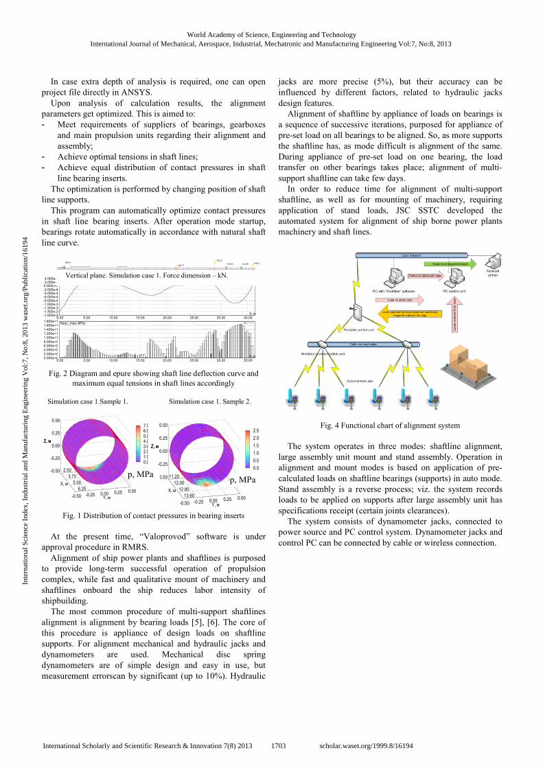
Fig. 2 Diagram and epure showing shaft line deflection curve and
maximum equal tensions in shaft lines accordingly
Fig. 1 Distribution of contact pressures in bearing inserts
At the present time, “Valoprovod” software is under
approval procedure in RMRS.
Alignment of ship power plants and shaftlines is purposed
to provide long-term successful operation of propulsion
complex, while fast and qualitative mount of machinery and
shaftlines onboard the ship reduces labor intensity of
shipbuilding.
The most common procedure of multi-support shaftlines
alignment is alignment by bearing loads [5], [6]. The core of
this procedure is appliance of design loads on shaftline
supports. For alignment mechanical and hydraulic jacks and
dynamometers are used. Mechanical disc spring
dynamometers are of simple design and easy in use, but
measurement errorscan by significant (up to 10%). Hydraulic
jacks are more precise (5%), but their accuracy can be
influenced by different factors, related to hydraulic jacks
design features.
Alignment of shaftline by appliance of loads on bearings is
a sequence of successive iterations, purposed for appliance of
pre-set load on all bearings to be aligned. So, as more supports
the shaftline has, as mode difficult is alignment of the same.
During appliance of pre-set load on one bearing, the load
transfer on other bearings takes place; alignment of multi-
support shaftline can take few days.
In order to reduce time for alignment of multi-support
shaftline, as well as for mounting of machinery, requiring
application of stand loads, JSC SSTC developed the
automated system for alignment of ship borne power plants
machinery and shaft lines.
Fig. 4 Functional chart of alignment system
The system operates in three modes: shaftline alignment,
large assembly unit mount and stand assembly. Operation in
alignment and mount modes is based on application of pre-
calculated loads on shaftline bearings (supports) in auto mode.
Stand assembly is a reverse process; viz. the system records
loads to be applied on supports after large assembly unit has
specifications receipt (certain joints clearances).
The system consists of dynamometer jacks, connected to
power source and PC control system. Dynamometer jacks and
control PC can be connected by cable or wireless connection.
15.29
598.41414.00 413.98
Вертикальная плоскость, расчётный случай- 1. Размерность сил- кНВертикальная плоскость, расчётный случай- 1. Размерность сил- кН
-268.77
-793.27
-489.28
Вертикальная плоскость, расчётный случай- 1. Размерность сил- кНВертикальная плоскость, расчётный случай- 1. Размерность сил- кНВертикальная плоскость, расчётный случай- 1. Размерность сил- кН
-1.600e-3-1.400e-3-1.200e-3-1.000e-3-8.000e-4-6.000e-4-4.000e-4-2.000e-4 0.000e+0 2.000e-4 4.000e-4
0.00 5.00 10.00 15.00 20.00 25.00 30.00 35.00
X, м
U_y, м РС-1
0.000e+0
2.000e+0
4.000e+0
6.000e+0 8.000e+0
1.000e+1
1.200e+1
1.400e+1
1.600e+1
1.800e+1
0.00 5.00 10.00 15.00 20.00 25.00 30.00 35.00
X, м
Seqv_max, МПа РС-1
2.50
3.75
5.00
6.25
-0.50 -0.25 0.00 0.25 0.50
-0.50
-0.25
0.00
0.25
0.50
Z, м
Расчётный случай- 1. Вставка- 1.
X, м
Y, м
Z, м
0.0 1.0 2.0 3.0 4.0 5.0 6.0 7.0
p, МПа 11.20
12.00
12.80
13.60
-0.50 -0.25 0.00 0.25 0.50
-0.50
-0.25
0.00
0.25
0.50
Z, м
X, м
Y, м
Z, м
0.0
0.5
1.0
1.5
2.0
2.5
p, МПа
Simulation case 1. Sample 2. Simulation case 1.Sample 1.
p, MPa
Vertical plane. Simulation case 1. Force dimension – kN.
p, MPa
World Academy of Science, Engineering and TechnologyInternational Journal of Mechanical, Aerospace, Industrial, Mechatronic and Manufacturing Engineering Vol:7, No:8, 2013
1703International Scholarly and Scientific Research & Innovation 7(8) 2013 scholar.waset.org/1999.8/16194
Inte
rnat
iona
l Sci
ence
Ind
ex, I
ndus
tria
l and
Man
ufac
turi
ng E
ngin
eeri
ng V
ol:7
, No:
8, 2
013
was
et.o
rg/P
ublic
atio
n/16
194
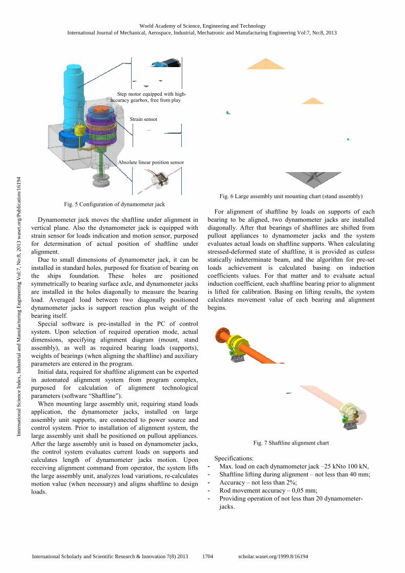
Fig. 5 Configuration of dynamometer jack
Dynamometer jack moves the shaftline under alignment in
vertical plane. Also the dynamometer jack is equipped with
strain sensor for loads indication and motion sensor, purposed
for determination of actual position of shaftline under
alignment.
Due to small dimensions of dynamometer jack, it can be
installed in standard holes, purposed for fixation of bearing on
the ships foundation. These holes are positioned
symmetrically to bearing surface axle, and dynamometer jacks
are installed in the holes diagonally to measure the bearing
load. Averaged load between two diagonally positioned
dynamometer jacks is support reaction plus weight of the
bearing itself.
Special software is pre-installed in the PC
system. Upon selection of required operation mod
dimensions, specifying alignment diagram (mount, stand
assembly), as well as required bearing loads (supports),
weights of bearings (when aligning the shaftline) and auxiliary
parameters are entered in the program.
Initial data, required for shaftline alignment can be exported
in automated alignment system from program complex,
purposed for calculation of alignment technological
parameters (software “Shaftline”).
When mounting large assembly unit, requiring stand loads
application, the dynamometer jacks, installed on large
assembly unit supports, are connected to power source and
control system. Prior to installation of alignment system, the
large assembly unit shall be positioned on pullout appliances.
After the large assembly unit is based on
the control system evaluates current loads on supports and
calculates length of dynamometer jacks motion. Upon
receiving alignment command from operator, the system lifts
the large assembly unit, analyzes load variations, re
motion value (when necessary) and aligns shaftline to design
loads.
Step motor equipped
accuracy gearbox,
Strain sensor
Absolute linear position sensor
Configuration of dynamometer jack
Dynamometer jack moves the shaftline under alignment in
vertical plane. Also the dynamometer jack is equipped with
strain sensor for loads indication and motion sensor, purposed
for determination of actual position of shaftline under
ll dimensions of dynamometer jack, it can be
installed in standard holes, purposed for fixation of bearing on
the ships foundation. These holes are positioned
symmetrically to bearing surface axle, and dynamometer jacks
to measure the bearing
load. Averaged load between two diagonally positioned
dynamometer jacks is support reaction plus weight of the
installed in the PC of control
system. Upon selection of required operation mode, actual
dimensions, specifying alignment diagram (mount, stand
assembly), as well as required bearing loads (supports),
weights of bearings (when aligning the shaftline) and auxiliary
ftline alignment can be exported
in automated alignment system from program complex,
purposed for calculation of alignment technological
When mounting large assembly unit, requiring stand loads
ter jacks, installed on large
assembly unit supports, are connected to power source and
control system. Prior to installation of alignment system, the
large assembly unit shall be positioned on pullout appliances.
After the large assembly unit is based on dynamometer jacks,
the control system evaluates current loads on supports and
calculates length of dynamometer jacks motion. Upon
receiving alignment command from operator, the system lifts
the large assembly unit, analyzes load variations, re-calculates
otion value (when necessary) and aligns shaftline to design
Fig. 6 Large assembly unit mounting
For alignment of shaftline by loads on supports of each
bearing to be aligned, two dynamometer jacks are installed
diagonally. After that bearings of shaftlines are shifted from
pullout appliances to dynamometer jacks and the system
evaluates actual loads on shaftline supports. When calculating
stressed-deformed state of shaftline, it is provided as cutless
statically indeterminate beam, and the algorithm for pre
loads achievement is calculated basing on induction
coefficients values. For that matter and to evaluate actual
induction coefficient, each shaftline bearing prior to alignment
is lifted for calibration. Basing on lifting results, the system
calculates movement value of each bearing and alignment
begins.
Fig. 7 Shaftline alignment chart
Specifications:
- Max. load on each dynamometer jack
- Shaftline lifting during alignment
- Accuracy – not less than
- Rod movement accuracy
- Providing operation of not
jacks.
equipped with high-
accuracy gearbox, free from play
Strain sensor
Absolute linear position sensor
Large assembly unit mounting chart (stand assembly)
For alignment of shaftline by loads on supports of each
bearing to be aligned, two dynamometer jacks are installed
diagonally. After that bearings of shaftlines are shifted from
pullout appliances to dynamometer jacks and the system
evaluates actual loads on shaftline supports. When calculating
deformed state of shaftline, it is provided as cutless
indeterminate beam, and the algorithm for pre-set
loads achievement is calculated basing on induction
coefficients values. For that matter and to evaluate actual
induction coefficient, each shaftline bearing prior to alignment
sing on lifting results, the system
calculates movement value of each bearing and alignment
Shaftline alignment chart
Max. load on each dynamometer jack –25 kNto 100 kN,
during alignment – not less than 40 mm;
2%;
– 0,05 mm;
Providing operation of not less than 20 dynamometer-
World Academy of Science, Engineering and TechnologyInternational Journal of Mechanical, Aerospace, Industrial, Mechatronic and Manufacturing Engineering Vol:7, No:8, 2013
1704International Scholarly and Scientific Research & Innovation 7(8) 2013 scholar.waset.org/1999.8/16194
Inte
rnat
iona
l Sci
ence
Ind
ex, I
ndus
tria
l and
Man
ufac
turi
ng E
ngin
eeri
ng V
ol:7
, No:
8, 2
013
was
et.o
rg/P
ublic
atio
n/16
194
REFERENCES
[1] Guidance notes on propulsion shafting alignment. American Bureau of Shipping. Houston, 2006
[2] Amit Batra, K. Shankar, S. Swarnamani. Propulsion shaft alignment
measurements on warships afloat and alignment solution using multi-objective optimization // Journal of Marine Engineering and
Technology. No.A9 2007. IIT Madras, Chennai, India
[3] Release 11.0 Documentation for ANSYS. ANSYS Inc., 2007. [4] Cook, Robert Davis. Finite element modeling for stress analysis / Robert
D. Cook. 1994
[5] V.N. Lubenko, Yu.A. Vyazovoy. Assembly of ship shaftlines. Saint-Petersburg, Russia, 2007.
[6] V.G. Nesterov. Aspects of alignment of shipshaftlines. // Symposium on mechanics. Saint-Petersburg, Russia, 2000.
World Academy of Science, Engineering and TechnologyInternational Journal of Mechanical, Aerospace, Industrial, Mechatronic and Manufacturing Engineering Vol:7, No:8, 2013
1705International Scholarly and Scientific Research & Innovation 7(8) 2013 scholar.waset.org/1999.8/16194
Inte
rnat
iona
l Sci
ence
Ind
ex, I
ndus
tria
l and
Man
ufac
turi
ng E
ngin
eeri
ng V
ol:7
, No:
8, 2
013
was
et.o
rg/P
ublic
atio
n/16
194