Embed Size (px)
Citation preview
adjusted for the 10 unit grid
DESIGNFLEX™ Shapes – LYRA®, CALLA®, OPTIMA®, ULTIMA® PanelsAssembly and Installation Instructions
1. GENERALThis system is unique to the ceilings industry. Please completely read all instructions before beginning installation to avoid potential re-work. Installation videos for this system are available at: www.armstrongceilings.com/shapesinstallation
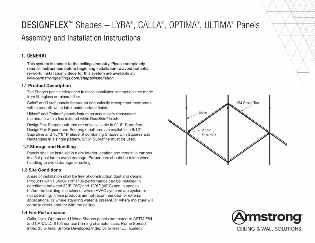
1.1 Product DescriptionThe Shapes panels referenced in these installation instructions are made from fiberglass or mineral fiber.
Calla® and Lyra® panels feature an acoustically transparent membrane with a smooth white latex paint surface finish.
Ultima® and Optima® panels feature an acoustically transparent membrane with a fine textured white DuraBrite® finish.
DesignFlex Shapes patterns are only available in 9/16" Suprafine. DesignFlex Square and Rectangle patterns are available in 9/16" Suprafine and 15/16" Prelude. If combining Shapes with Squares and Rectangles in a single pattern, 9/16" Suprafine must be used.
1.2 Storage and HandlingPanels shall be installed in a dry interior location and remain in cartons in a flat position to avoid damage. Proper care should be taken when handling to avoid damage or soiling.
1.3 Site ConditionsAreas of installation shall be free of construction dust and debris. Products with HumiGuard® Plus performance can be installed in conditions between 32°F (0°C) and 120°F (49°C) and in spaces before the building is enclosed, where HVAC systems are cycled or not operating. These products are not recommended for exterior applications, or where standing water is present, or where moisture will come in direct contact with the ceiling.
1.4 Fire PerformanceCalla, Lyra, Optima and Ultima Shapes panels are tested to ASTM E84 and CAN/ULC S102 surface burning characteristics. Flame Spread Index 25 or less. Smoke Developed Index 50 or less (UL labeled).
Main
XM Cross Tee
AngleBrackets
2
1.5 Fire PerformanceImportant Safety Information
• This is a custom design and installation.
• This product can’t be installed in a sloped application.
• The final design and installation parameters are the responsibility of your design team.
• Project specific evaluation for compliance with building codes is recommended.
• Armstrong Ceilings has evaluated certain design configurations. Detailed instructions for those designs are available at the DESIGNFlex™ Shapes Gallery located at www.armstrongceilings.com/patterngallery
• All information provided pertains solely to Armstrong DESIGNFlex ceilings and components. Any ceiling panel, grid, component or accessory substitutions are not covered by these instructions or warranty.
1.5.1 Working with Fiberglass and Mineral Fiber Products
1.5.2 Precautionary Measures: During the installation, be certain that the work site is well ventilated and avoid breathing dust. If high dust levels are anticipated during installation, such as with the use of power tools, use appropriate NIOSH designated dust respirator. All power cutting tools must be equipped with dust collectors. Avoid contact with skin or eyes.
1.5.3 First Aid Measures: If contact occurs, flush eyes and skin irritation with plenty of water for at least 15 minutes and remove contaminated clothing. Wash work clothes with warm water and mild soap. Refer to Armstrong World Industries SDS (which includes information on established occupational exposure limits), available at armstrongceilings.com/commercial
Protect Finished Edges – Do not stand the panels on edge. Keep them face-to-face, back-to-back, and flat on the work surface.
1.6 WarrantyAn installed Shapes ceiling system will be warranted for a period of 10 years. Instructions within this document must be followed and the system must only use Armstrong Ceiling Solutions components for the warranty to be valid. For full warranty information, please go to armstrongceilings.com/warranty
1.7 Plenum1.7.1 Installation of Calla, Ultima, Optima and Lyra Shapes panels requires a minimum of 6" of space in the plenum.
NOTE: Light fixtures and air handling systems may require more space and may determine the minimum plenum height for the installation.
1.7.2 Independent support of MEP devices is required. There must not be weight from any lights, diffusers, speakers or similar devices supported by mineral fiber or fiberglass shapes panels. All such devices shall be independently supported.
1.8 CleaningDust and loose dirt may easily be removed by brushing or with a vacuum cleaner. Vacuum cleaner brush attachments such as those designed for cleaning upholstery or walls do the best job. Be certain to clean in one direction only. This will prevent rubbing dust into the surface of the ceiling. Use a clean, dry, soft, white cloth to wipe off any dirt or greasy fingerprints. If this does not clean the panel, use a damp, clean, soft, white cloth or sponge with a mild detergent to wipe the panel. Remove any remaining moisture with a dry cloth.
2. DESIGN AND INSTALLATION CONSIDERATIONS
2.1 Layout2.1.1 This system is designed to give maximum design flexibility while building off of 4' or 2' on center (O.C.) spacing of standard main beams. A mix of special length and standard length cross tees span between the mains at various angles. This can create an assortment of different shaped grid openings for panels. Refer to your job specific drawings for layout and specific component locations.
2.1.2 Refer to the architectural ceiling plans for suspension system and panel orientation layout.
2.2 Directionality2.2.1 Suspension System: The suspension system must be installed in accordance with the architectural ceiling plans. All grid components are non-directional, except for the Perimeter Cross Tees, which only have an end detail on one end.2.2.2 Panel substrate types: All Lyra® and Calla® Shapes panels are 180 degrees directional due to finish visual. Optima® and Ultima® Shapes panels are non-directional due to finish visual.

3
2.2.3 Panel shapes: All panels must be installed in a specific orientation in order to match the openings of the grid. The specified layout design will dictate the direction of the panels. Panels have a “base" side that runs parallel with the main beams. Because of this, all panels that are not right triangles, can only be installed in one orientation in relation to the main beam direction. Right triangle panels are the only shapes for which layouts can be designed with the panels quarter turned so that the “base" side is perpendicular to the mains.
This must be taken into consideration when designing an installation that mixes squares/rectangles.
NOTE: DesignFlex Shapes patterns are only available in 9/16" Suprafine. DesignFlex Square and Rectangle patterns are available in 9/16" Suprafine and 15/16" Prelude. If combining Shapes with Squares and Rectangles in a single pattern, 9/16" Suprafine must be used.
2.3 Panel OffsetThe finish face of the tegular panels drops 1/4" below the face of the grid (Fig 2).
The installed height of components that interface with these ceiling panels, such as sprinkler heads and light fixture trim rings, will have to be adjusted to accommodate this 1/4" offset.
Square lay-in panels do not drop below the face of the grid (Fig 3).
2.4 Plenum2.4.1 All Shapes panels are lay-in type panels and require space in the plenum for installation.
2.4.2 A minimum of 6" above the grid is recommended for all installations. This will allow all panel sizes and shapes to be installed without damage.
2.5 Sprinklers2.5.1 Tegular Shapes panels drop 1/4" below the face of the grid. Sprinkler heads need to be installed at the proper height to accommodate this drop. See local building code officials or fire protection engineer, when necessary.
Shapes installations can have an assortment of grid layouts resulting in some modules not having an opposite parallel side (triangles). Sprinklers that have brackets that attach to the grid (e.g. FlexHead® sprinklers) must attach to parallel mains.
(Fig 2)
(Fig 3)
1/4"
1/4"
4
2.6 Approximate System Weight2.6.1 Overall system weight will be primarily based on the panel type. • Lyra panels weigh 0.50lbs/SF • Calla panels weigh 1.1lbs/SF • Optima panels weigh 0.50lbs/SF • Ultima panels weigh 1.1lbs/SF2.6.2 The weight of the suspension system ranges between 0.2 – 0.4lbs/SF.2.6.3 Hanger connections to the structure must follow the manufacturer’s instructions and referenced code. Average system weight per square foot will vary based on panel types and layout.
2.7 Accessibility2.7.1 Full-size panels without penetrations are accessible. Border panels may not be accessible based on the perimeter interface and the installation method.
2.8 PerimetersThe way that perimeters are addressed will vary based on the design and layout within the space. These different methods for addressing the perimeters may require separate components and additional time to install compared to traditional installations.
2.9 Fixture IntegrationDue to the non-standard grid openings that are created for the Shapes system, standard fixtures may not be compatible. For details on fixture integration through TechZone® layouts, and integration partners, see section 8.
2.10 EstimatingFor guidance on estimating installed costs, contact your Armstrong Ceilings Rep or Techline.
2.11 Seismic InstallationsCeiling areas over 1,000 SF with back-to-back (opposing) bracket connections to the mains can be braced following standard spacing guidelines. If single bracket connections occur (no opposing bracket occupying the same rout hole) consult a professional engineer for lateral force bracing placement.
3. ACCESSORIES3.1 Suspension System Accessories
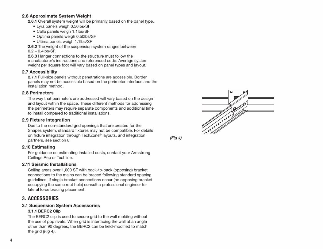
3.1.1 BERC2 ClipThe BERC2 clip is used to secure grid to the wall molding without the use of pop rivets. When grid is interfacing the wall at an angle other than 90 degrees, the BERC2 can be field-modified to match the grid (Fig 4).
(Fig 4)
5
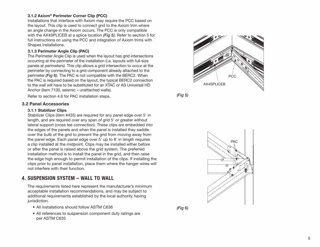
3.1.2 Axiom® Perimeter Corner Clip (PCC)Installations that interface with Axiom may require the PCC based on the layout. This clip is used to connect grid to the Axiom trim where an angle change in the Axiom occurs. The PCC is only compatible with the AX4SPLICEB at a splice location (Fig 5). Refer to section 5 for full instructions on using the PCC and integration of Axiom trims with Shapes installations.
3.1.3 Perimeter Angle Clip (PAC)The Perimeter Angle Clip is used when the layout has grid intersections occurring at the perimeter of the installation (i.e. layouts with full-size panels at perimeters). This clip allows a grid intersection to occur at the perimeter by connecting to a grid component already attached to the perimeter (Fig 6). The PAC is not compatible with the BERC2. When the PAC is required based on the layout, the typical BERC2 connection to the wall will have to be substituted for an XTAC or AS Universal HD Anchor (item 7100, seismic – unattached walls).
Refer to section 4.6 for PAC installation steps.
3.2 Panel Accessories3.1.1 Stabilizer ClipsStabilizer Clips (item #435) are required for any panel edge over 5' in length, and are required over any span of grid 5' or greater without lateral support (cross tee connection). These clips are embedded into the edges of the panels and when the panel is installed they saddle over the bulb of the grid to prevent the grid from moving away from the panel edge. Each panel edge over 5' up to 8' in length requires a clip installed at the midpoint. Clips may be installed either before or after the panel is raised above the grid system. The preferred installation method is to install the panel in the grid, and then raise the edge high enough to permit installation of the clips. If installing the clips prior to panel installation, place them where the hanger wires will not interfere with their function.
4. SUSPENSION SYSTEM – WALL TO WALLThe requirements listed here represent the manufacturer’s minimum acceptable installation recommendations, and may be subject to additional requirements established by the local authority having jurisdiction.
• All installations should follow ASTM C636
• All references to suspension component duty ratings are per ASTM C635
(Fig 5)
(Fig 6)
AX4SPLICEB
PCC
PAC
6
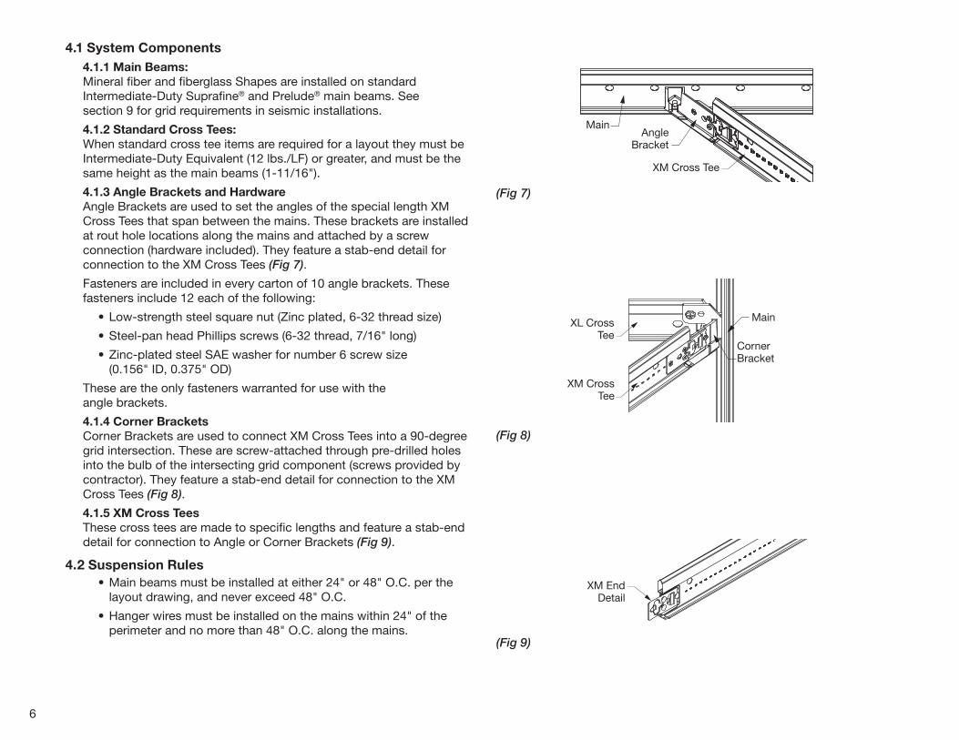
(Fig 7)
(Fig 8)
(Fig 9)
Main
CornerBracket
XM CrossTee
XL CrossTee
4.1 System Components4.1.1 Main Beams:Mineral fiber and fiberglass Shapes are installed on standard Intermediate-Duty Suprafine® and Prelude® main beams. See section 9 for grid requirements in seismic installations.
4.1.2 Standard Cross Tees: When standard cross tee items are required for a layout they must be Intermediate-Duty Equivalent (12 lbs./LF) or greater, and must be the same height as the main beams (1-11/16").
4.1.3 Angle Brackets and Hardware Angle Brackets are used to set the angles of the special length XM Cross Tees that span between the mains. These brackets are installed at rout hole locations along the mains and attached by a screw connection (hardware included). They feature a stab-end detail for connection to the XM Cross Tees (Fig 7).
Fasteners are included in every carton of 10 angle brackets. These fasteners include 12 each of the following:
• Low-strength steel square nut (Zinc plated, 6-32 thread size)
• Steel-pan head Phillips screws (6-32 thread, 7/16" long)
• Zinc-plated steel SAE washer for number 6 screw size (0.156" ID, 0.375" OD)
These are the only fasteners warranted for use with the angle brackets.
4.1.4 Corner Brackets Corner Brackets are used to connect XM Cross Tees into a 90-degree grid intersection. These are screw-attached through pre-drilled holes into the bulb of the intersecting grid component (screws provided by contractor). They feature a stab-end detail for connection to the XM Cross Tees (Fig 8).
4.1.5 XM Cross Tees These cross tees are made to specific lengths and feature a stab-end detail for connection to Angle or Corner Brackets (Fig 9).
4.2 Suspension Rules • Main beams must be installed at either 24" or 48" O.C. per the
layout drawing, and never exceed 48" O.C.
• Hanger wires must be installed on the mains within 24" of the perimeter and no more than 48" O.C. along the mains.
XM EndDetail
MainAngle
Bracket
XM Cross Tee
7
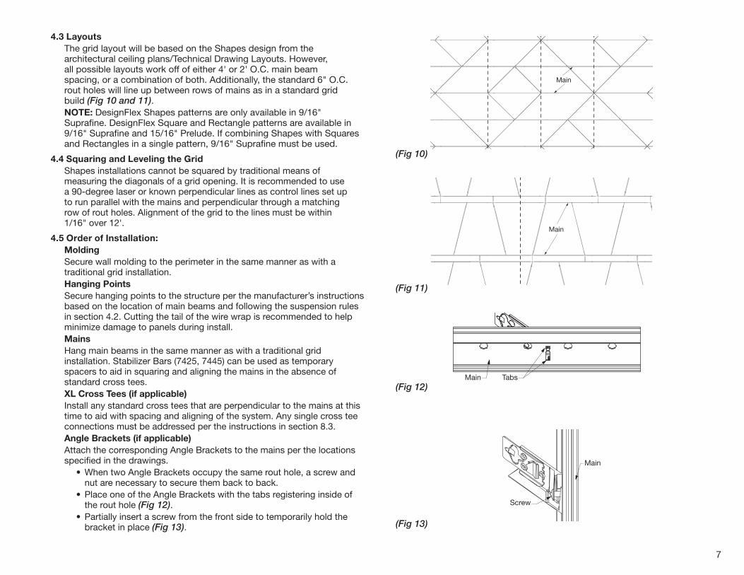
4.3 LayoutsThe grid layout will be based on the Shapes design from the architectural ceiling plans/Technical Drawing Layouts. However, all possible layouts work off of either 4' or 2' O.C. main beam spacing, or a combination of both. Additionally, the standard 6" O.C. rout holes will line up between rows of mains as in a standard grid build (Fig 10 and 11).NOTE: DesignFlex Shapes patterns are only available in 9/16" Suprafine. DesignFlex Square and Rectangle patterns are available in 9/16" Suprafine and 15/16" Prelude. If combining Shapes with Squares and Rectangles in a single pattern, 9/16" Suprafine must be used.
4.4 Squaring and Leveling the GridShapes installations cannot be squared by traditional means of measuring the diagonals of a grid opening. It is recommended to use a 90-degree laser or known perpendicular lines as control lines set up to run parallel with the mains and perpendicular through a matching row of rout holes. Alignment of the grid to the lines must be within 1/16" over 12'.
4.5 Order of Installation:Molding Secure wall molding to the perimeter in the same manner as with a traditional grid installation.Hanging Points Secure hanging points to the structure per the manufacturer’s instructions based on the location of main beams and following the suspension rules in section 4.2. Cutting the tail of the wire wrap is recommended to help minimize damage to panels during install.MainsHang main beams in the same manner as with a traditional grid installation. Stabilizer Bars (7425, 7445) can be used as temporary spacers to aid in squaring and aligning the mains in the absence of standard cross tees.XL Cross Tees (if applicable)Install any standard cross tees that are perpendicular to the mains at this time to aid with spacing and aligning of the system. Any single cross tee connections must be addressed per the instructions in section 8.3.Angle Brackets (if applicable)Attach the corresponding Angle Brackets to the mains per the locations specified in the drawings. • When two Angle Brackets occupy the same rout hole, a screw and
nut are necessary to secure them back to back. • Place one of the Angle Brackets with the tabs registering inside of
the rout hole (Fig 12). • Partially insert a screw from the front side to temporarily hold the
bracket in place (Fig 13).
(Fig 10)
(Fig 11)
(Fig 12)
(Fig 13)
Main
Main
Main Tabs
Main
Screw
8
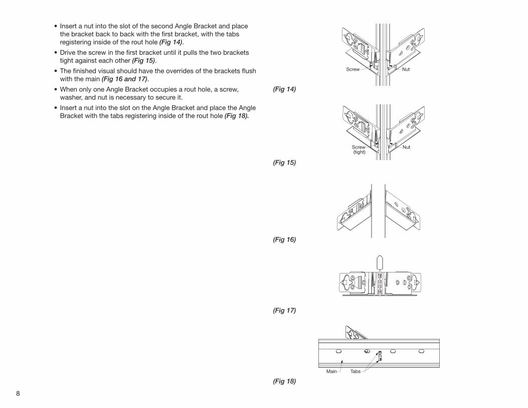
• Insert a nut into the slot of the second Angle Bracket and place the bracket back to back with the first bracket, with the tabs registering inside of the rout hole (Fig 14).
• Drive the screw in the first bracket until it pulls the two brackets tight against each other (Fig 15).
• The finished visual should have the overrides of the brackets flush with the main (Fig 16 and 17).
• When only one Angle Bracket occupies a rout hole, a screw, washer, and nut is necessary to secure it.
• Insert a nut into the slot on the Angle Bracket and place the Angle Bracket with the tabs registering inside of the rout hole (Fig 18).
(Fig 14)
(Fig 15)
(Fig 16)
(Fig 17)
(Fig 18)
Screw Nut
Screw(tight)
Nut
Main Tabs
9
(Fig 19)
(Fig 20)
(Fig 21)
(Fig 22)
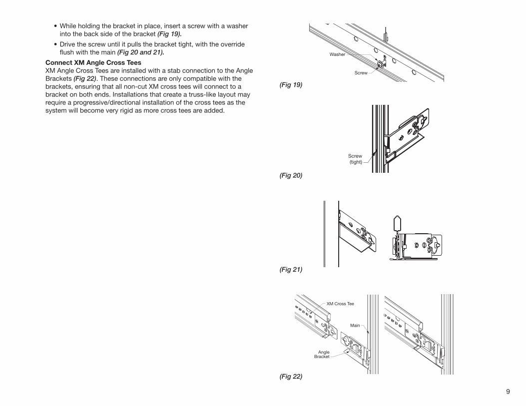
• While holding the bracket in place, insert a screw with a washer into the back side of the bracket (Fig 19).
• Drive the screw until it pulls the bracket tight, with the override flush with the main (Fig 20 and 21).
Connect XM Angle Cross TeesXM Angle Cross Tees are installed with a stab connection to the Angle Brackets (Fig 22). These connections are only compatible with the brackets, ensuring that all non-cut XM cross tees will connect to a bracket on both ends. Installations that create a truss-like layout may require a progressive/directional installation of the cross tees as the system will become very rigid as more cross tees are added.
Screw
Washer
Screw(tight)
Main
AngleBracket
XM Cross Tee
10
(Fig 23)
(Fig 24)
(Fig 26)
(Fig 25)
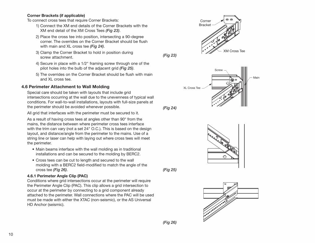
Corner Brackets (if applicable)To connect cross tees that require Corner Brackets: 1) Connect the XM end details of the Corner Brackets with the
XM end detail of the XM Cross Tees (Fig 23).
2) Place the cross tee into position, intersecting a 90-degree corner. The overrides on the Corner Bracket should be flush with main and XL cross tee (Fig 24).
3) Clamp the Corner Bracket to hold in position during screw attachment.
4) Secure in place with a 1/2" framing screw through one of the pilot holes into the bulb of the adjacent grid (Fig 25).
5) The overrides on the Corner Bracket should be flush with main and XL cross tee.
4.6 Perimeter Attachment to Wall MoldingSpecial care should be taken with layouts that include grid intersections occurring at the wall due to the unevenness of typical wall conditions. For wall-to-wall installations, layouts with full-size panels at the perimeter should be avoided whenever possible.
All grid that interfaces with the perimeter must be secured to it.
As a result of having cross tees at angles other than 90° from the mains, the distance between where perimeter cross tees interface with the trim can vary (not a set 24" O.C.). This is based on the design layout, and distance/angle from the perimeter to the mains. Use of a string line or laser can help with laying out where cross tees will meet the perimeter.
• Main beams interface with the wall molding as in traditional installations and can be secured to the molding by BERC2.
• Cross tees can be cut to length and secured to the wall molding with a BERC2 field-modified to match the angle of the cross tee (Fig 26).
4.6.1 Perimeter Angle Clip (PAC)Conditions where grid intersections occur at the perimeter will require the Perimeter Angle Clip (PAC). This clip allows a grid intersection to occur at the perimeter by connecting to a grid component already attached to the perimeter. Wall connections where the PAC will be used must be made with either the XTAC (non-seismic), or the AS Universal HD Anchor (seismic).
Main
CornerBracket
XM Cross Tee
XL Cross Tee
Screw
Main
CornerBracket
XM Cross Tee
XL Cross Tee
Screw
Main
CornerBracket
XM Cross Tee
XL Cross Tee
Screw
11
(Fig 30)
(Fig 29)
(Fig 28)
(Fig 27)
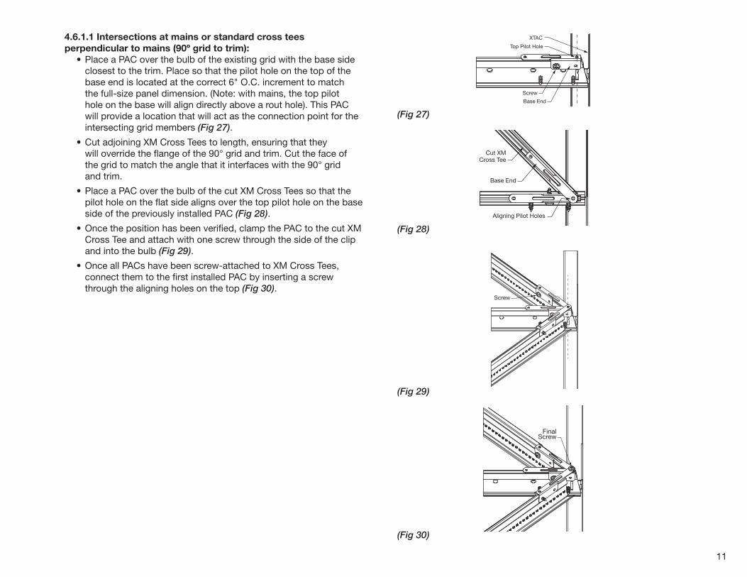
4.6.1.1 Intersections at mains or standard cross tees perpendicular to mains (90º grid to trim): • Place a PAC over the bulb of the existing grid with the base side
closest to the trim. Place so that the pilot hole on the top of the base end is located at the correct 6" O.C. increment to match the full-size panel dimension. (Note: with mains, the top pilot hole on the base will align directly above a rout hole). This PAC will provide a location that will act as the connection point for the intersecting grid members (Fig 27).
• Cut adjoining XM Cross Tees to length, ensuring that they will override the flange of the 90° grid and trim. Cut the face of the grid to match the angle that it interfaces with the 90° grid and trim.
• Place a PAC over the bulb of the cut XM Cross Tees so that the pilot hole on the flat side aligns over the top pilot hole on the base side of the previously installed PAC (Fig 28).
• Once the position has been verified, clamp the PAC to the cut XM Cross Tee and attach with one screw through the side of the clip and into the bulb (Fig 29).
• Once all PACs have been screw-attached to XM Cross Tees, connect them to the first installed PAC by inserting a screw through the aligning holes on the top (Fig 30).
Top Pilot Hole
Screw
XTAC
Base End
Aligning Pilot Holes
Cut XMCross Tee
Base End
Screw
FinalScrew
12
(Fig 33)
(Fig 34)
(Fig 32)
(Fig 31)
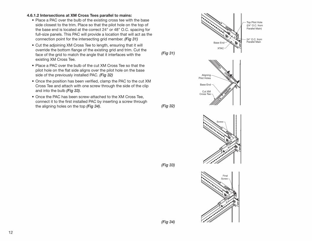
4.6.1.2 Intersections at XM Cross Tees parallel to mains: • Place a PAC over the bulb of the existing cross tee with the base
side closest to the trim. Place so that the pilot hole on the top of the base end is located at the correct 24" or 48" O.C. spacing for full-size panels. This PAC will provide a location that will act as the connection point for the intersecting grid member. (Fig 31)
• Cut the adjoining XM Cross Tee to length, ensuring that it will override the bottom flange of the existing grid and trim. Cut the face of the grid to match the angle that it interfaces with the existing XM Cross Tee.
• Place a PAC over the bulb of the cut XM Cross Tee so that the pilot hole on the flat side aligns over the pilot hole on the base side of the previously installed PAC. (Fig 32)
• Once the position has been verified, clamp the PAC to the cut XM Cross Tee and attach with one screw through the side of the clip and into the bulb (Fig 33).
• Once the PAC has been screw-attached to the XM Cross Tee, connect it to the first installed PAC by inserting a screw through the aligning holes on the top (Fig 34).
24" O.C. fromParallel MainBase End
XTAC
Top Pilot Hole(24" O.C. from Parallel Main)
AligningPilot Holes
Cut XMCross Tee
Base End
Screw
FinalScrew
13
(Fig 35)
5. FLOATING PERIMETERS / TRIM FOR DISCONTINUOUS CEILINGSInstallations with Axiom® Trim are better for full-size panel designs and layouts as the overall dimensions of the install, and the angles of the trim can be controlled.
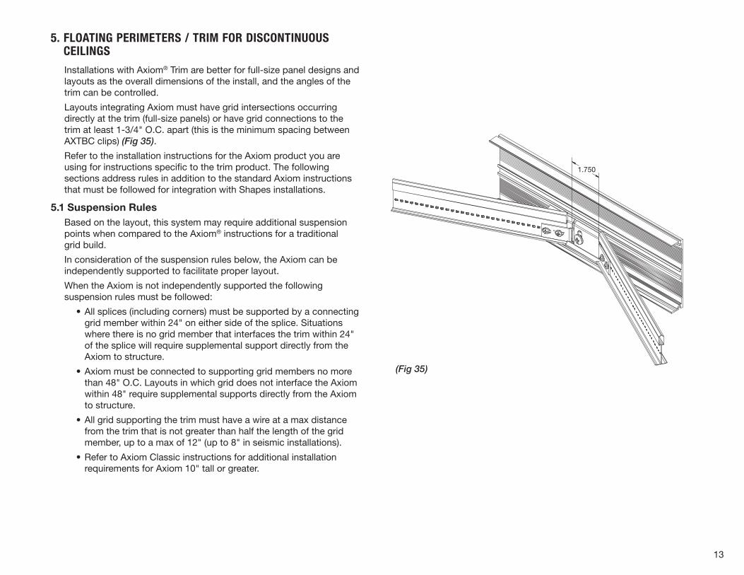
Layouts integrating Axiom must have grid intersections occurring directly at the trim (full-size panels) or have grid connections to the trim at least 1-3/4" O.C. apart (this is the minimum spacing between AXTBC clips) (Fig 35).
Refer to the installation instructions for the Axiom product you are using for instructions specific to the trim product. The following sections address rules in addition to the standard Axiom instructions that must be followed for integration with Shapes installations.
5.1 Suspension RulesBased on the layout, this system may require additional suspension points when compared to the Axiom® instructions for a traditional grid build.
In consideration of the suspension rules below, the Axiom can be independently supported to facilitate proper layout.
When the Axiom is not independently supported the following suspension rules must be followed:
• All splices (including corners) must be supported by a connecting grid member within 24" on either side of the splice. Situations where there is no grid member that interfaces the trim within 24" of the splice will require supplemental support directly from the Axiom to structure.
• Axiom must be connected to supporting grid members no more than 48" O.C. Layouts in which grid does not interface the Axiom within 48" require supplemental supports directly from the Axiom to structure.
• All grid supporting the trim must have a wire at a max distance from the trim that is not greater than half the length of the grid member, up to a max of 12" (up to 8" in seismic installations).
• Refer to Axiom Classic instructions for additional installation requirements for Axiom 10" tall or greater.
1.750
14
(Fig 39)
(Fig 38)
(Fig 37)
(Fig 36)
5.2 Grid Attachment • All main beams are attached to Axiom by the standard AXTBC
connection.
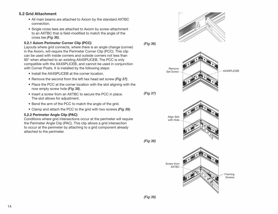
• Single cross tees are attached to Axiom by screw-attachment to an AXTBC that is field-modified to match the angle of the cross tee (Fig 36).
5.2.1 Axiom Perimeter Corner Clip (PCC) Layouts where grid connects, where there is an angle change (corner) in the Axiom, will require the Perimeter Corner Clip (PCC). This clip can be used with inside corners and outside corners not less than 90° when attached to an existing AX4SPLICEB. The PCC is only compatible with the AX4SPLICEB, and cannot be used in conjunction with Corner Posts. It is installed by the following steps:
• Install the AX4SPLICEB at the corner location.
• Remove the second from the left hex head set screw (Fig 37).
• Place the PCC at the corner location with the slot aligning with the now empty screw hole (Fig 38).
• Insert a screw from an AXTBC to secure the PCC in place. The slot allows for adjustment.
• Bend the arm of the PCC to match the angle of the grid.
• Clamp and attach the PCC to the grid with two screws (Fig 39).
5.2.2 Perimeter Angle Clip (PAC) Conditions where grid intersections occur at the perimeter will require the Perimeter Angle Clip (PAC). This clip allows a grid intersection to occur at the perimeter by attaching to a grid component already attached to the perimeter.
RemoveSet Screw AX4SPLICEB
Align Slotwith Hole
Screw fromAXTBC
FramingScrews
15
(Fig 40)
(Fig 41)
(Fig 42)
(Fig 43)
It is installed by the following steps:
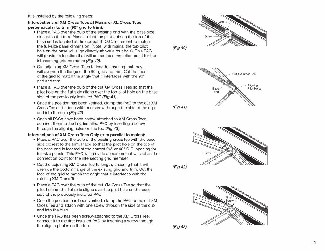
Intersections of XM Cross Tees at Mains or XL Cross Tees perpendicular to trim (90° grid to trim): • Place a PAC over the bulb of the existing grid with the base side
closest to the trim. Place so that the pilot hole on the top of the base end is located at the correct 6" O.C. increment to match the full-size panel dimension. (Note: with mains, the top pilot hole on the base will align directly above a rout hole). This PAC will provide a location that will act as the connection point for the intersecting grid members (Fig 40).
• Cut adjoining XM Cross Tees to length, ensuring that they will override the flange of the 90° grid and trim. Cut the face of the grid to match the angle that it interfaces with the 90° grid and trim.
• Place a PAC over the bulb of the cut XM Cross Tees so that the pilot hole on the flat side aligns over the top pilot hole on the base side of the previously installed PAC (Fig 41).
• Once the position has been verified, clamp the PAC to the cut XM Cross Tee and attach with one screw through the side of the clip and into the bulb (Fig 42).
• Once all PACs have been screw-attached to XM Cross Tees, connect them to the first installed PAC by inserting a screw through the aligning holes on the top (Fig 43).
Intersections of XM Cross Tees Only (trim parallel to mains): • Place a PAC over the bulb of the existing cross tee with the base
side closest to the trim. Place so that the pilot hole on the top of the base end is located at the correct 24" or 48" O.C. spacing for full-size panels. This PAC will provide a location that will act as the connection point for the intersecting grid member.
• Cut the adjoining XM Cross Tee to length, ensuring that it will override the bottom flange of the existing grid and trim. Cut the face of the grid to match the angle that it interfaces with the existing XM Cross Tee.
• Place a PAC over the bulb of the cut XM Cross Tee so that the pilot hole on the flat side aligns over the pilot hole on the base side of the previously installed PAC.
• Once the position has been verified, clamp the PAC to the cut XM Cross Tee and attach with one screw through the side of the clip and into the bulb.
• Once the PAC has been screw-attached to the XM Cross Tee, connect it to the first installed PAC by inserting a screw through the aligning holes on the top.
AligningPilot Holes
Cut XM Cross Tee
Screw
AXTBC
BaseEnd
Screw
FinalScrew
AligningPilot Holes
Cut XM Cross Tee
Screw
AXTBC
BaseEnd
Screw
FinalScrew
AligningPilot Holes
Cut XM Cross Tee
Screw
AXTBC
BaseEnd
Screw
FinalScrew
AligningPilot Holes
Cut XM Cross Tee
Screw
AXTBC
BaseEnd
Screw
FinalScrew
16
(Fig 44)
6. TRANSITIONS
6.1 Using Axiom Transitions 6.1.1 Suspension Rules • Suspension of Axiom® transitions must follow the same rules
outlined in section 5.1 for Axiom trim.
6.1.2 Grid Attachment • Grid attachment rules are TBD based on floating perimeter
attachment solutions.
• Grid attachment to Axiom transitions must follow the same rules outlined in section 5.2 Grid Attachment for Axiom Trim.
• All main beams are attached to Axiom transitions by the standard AXTBC or AXCCLT connection (refer to the Axiom Transitions instructions).
• Single cross tees are attached to Axiom transitions by screw attachment to an AXTBC or AXCCLT that is field-bent to match the angle of the cross tee.
• Conditions where grid intersections occur at the transition will require the Perimeter Angle Clip (PAC). This clip allows a grid intersection to occur at the transition by connecting to a grid component already attached to the transition. See section 4.6 for installation steps and details.
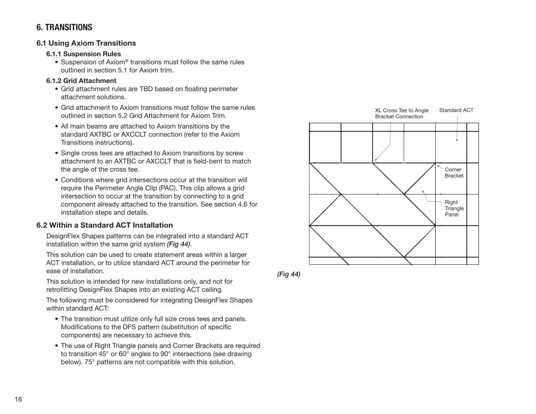
6.2 Within a Standard ACT InstallationDesignFlex Shapes patterns can be integrated into a standard ACT installation within the same grid system (Fig 44).
This solution can be used to create statement areas within a larger ACT installation, or to utilize standard ACT around the perimeter for ease of installation.
This solution is intended for new installations only, and not for retrofitting DesignFlex Shapes into an existing ACT ceiling.
The following must be considered for integrating DesignFlex Shapes within standard ACT:
• The transition must utilize only full size cross tees and panels. Modifications to the DFS pattern (substitution of specific components) are necessary to achieve this.
• The use of Right Triangle panels and Corner Brackets are required to transition 45° or 60° angles to 90° intersections (see drawing below). 75° patterns are not compatible with this solution.
XL Cross Tee to AngleBracket Connection
Standard ACT
CornerBracket
RightTrianglePanel
17
(Fig 45)
(Fig 46)
• Transitions from DFS to standard ACT between adjacent rows of mains will require the use of GC3W’s to secure XL cross tees to the main where Angle Brackets occupy the rout holes (see XL to Angle Bracket connection in above detail)
Contact Techline for assistance with layouts integrating a DesignFlex Shapes pattern within a standard ACT installation.
7. PANELSMineral fiber and fiberglass Shapes panels are specifically designed for proper fit into Shapes grid openings. Cutting panels or other materials to fit into the grid openings is not recommended and not warranted.
7.1 Edge Details/InterfaceShapes panels are available in the following edge details:
• Lyra®: Square Tegular for 9/16" Suprafine®
• Calla®: Square Tegular for 9/16" Suprafine
• Optima®: Square Tegular for 9/16" Suprafine, Square Lay-in for 15/16" Prelude® for Square and Rectangle patterns only
• Ultima®: Beveled Tegular for 9/16" Suprafine, Square Lay-in for 15/16" Prelude® for Square and Rectangle patterns only
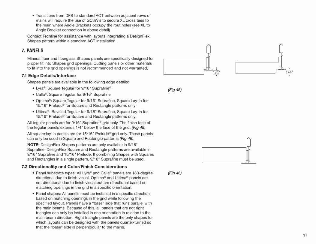
All tegular panels are for 9/16" Suprafine® grid only. The finish face of the tegular panels extends 1/4" below the face of the grid. (Fig 45)
All square lay-in panels are for 15/16" Prelude® grid only. These panels can only be used in Square and Rectangle patterns (Fig 46).
NOTE: DesignFlex Shapes patterns are only available in 9/16" Suprafine. DesignFlex Square and Rectangle patterns are available in 9/16" Suprafine and 15/16" Prelude. If combining Shapes with Squares and Rectangles in a single pattern, 9/16" Suprafine must be used.
7.2 Directionality and Color/Finish Considerations • Panel substrate types: All Lyra® and Calla® panels are 180-degree
directional due to finish visual. Optima® and Ultima® panels are not directional due to finish visual but are directional based on matching openings in the grid in a specific orientation.
• Panel shapes: All panels must be installed in a specific direction based on matching openings in the grid while following the specified layout. Panels have a “base" side that runs parallel with the main beams. Because of this, all panels that are not right triangles can only be installed in one orientation in relation to the main beam direction. Right triangle panels are the only shapes for which layouts can be designed with the panels quarter-turned so that the “base” side is perpendicular to the mains.
1/4"1/4"
18
(Fig 47)
(Fig 48)
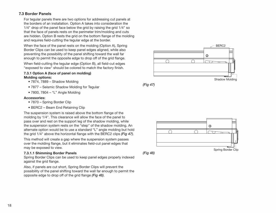
7.3 Border PanelsFor tegular panels there are two options for addressing cut panels at the borders of an installation. Option A takes into consideration the 1/4" drop of the panel face below the grid by raising the grid 1/4" so that the face of panels rests on the perimeter trim/molding and cuts are hidden. Option B rests the grid on the bottom flange of the molding and requires field-cutting the tegular edge at the border.
When the face of the panel rests on the molding (Option A), Spring Border Clips can be used to keep panel edges aligned, while also preventing the possibility of the panel shifting toward the wall far enough to permit the opposite edge to drop off of the grid flange.
When field-cutting the tegular edge (Option B), all field-cut edges “exposed to view" should be colored to match the factory finish.
7.3.1 Option A (face of panel on molding)Molding options: • 7874, 7889 – Shadow Molding
• 7877 – Seismic Shadow Molding for Tegular
• 7800, 7804 – “L” Angle Molding
Accessories: • 7870 – Spring Border Clip
• BERC2 – Beam End Retaining Clip
The suspension system is raised above the bottom flange of the molding by 1/4". This clearance will allow the face of the panel to pass over and rest on the support leg of the shadow molding, while the suspension system rests on the “step" of the shadow molding. An alternate option would be to use a standard “L” angle molding but hold the grid 1/4" above the horizontal flange with the BERC2 clips (Fig 47).
This method will create a gap where the suspension system passes over the molding flange, but it eliminates field-cut panel edges that may be exposed to view.
7.3.1.1 Shimming Border PanelsSpring Border Clips can be used to keep panel edges properly indexed against the grid flange.
Also, if panels are cut short, Spring Border Clips will prevent the possibility of the panel shifting toward the wall far enough to permit the opposite edge to drop off of the grid flange (Fig 48).
BERC2
Shadow Molding
Spring Border Clip
19
(Fig 49)
(Fig 50)
(Fig 51)
(Fig 52)
7.3.2 Option B (face of grid on molding)Molding: • 7800, 7804 – “L” Angle Molding
Accessories: • BERC2 – Beam End Retaining Clip
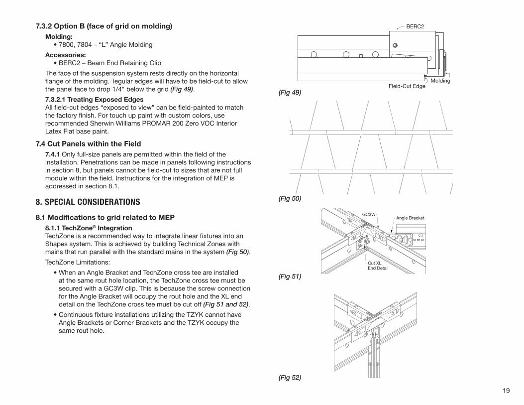
The face of the suspension system rests directly on the horizontal flange of the molding. Tegular edges will have to be field-cut to allow the panel face to drop 1/4" below the grid (Fig 49).
7.3.2.1 Treating Exposed EdgesAll field-cut edges “exposed to view” can be field-painted to match the factory finish. For touch up paint with custom colors, use recommended Sherwin Williams PROMAR 200 Zero VOC Interior Latex Flat base paint.
7.4 Cut Panels within the Field7.4.1 Only full-size panels are permitted within the field of the installation. Penetrations can be made in panels following instructions in section 8, but panels cannot be field-cut to sizes that are not full module within the field. Instructions for the integration of MEP is addressed in section 8.1.
8. SPECIAL CONSIDERATIONS
8.1 Modifications to grid related to MEP8.1.1 TechZone® IntegrationTechZone is a recommended way to integrate linear fixtures into an Shapes system. This is achieved by building Technical Zones with mains that run parallel with the standard mains in the system (Fig 50).
TechZone Limitations:
• When an Angle Bracket and TechZone cross tee are installed at the same rout hole location, the TechZone cross tee must be secured with a GC3W clip. This is because the screw connection for the Angle Bracket will occupy the rout hole and the XL end detail on the TechZone cross tee must be cut off (Fig 51 and 52).
• Continuous fixture installations utilizing the TZYK cannot have Angle Brackets or Corner Brackets and the TZYK occupy the same rout hole.
BERC2
MoldingField-Cut Edge
Main
GC3WAngle Bracket
Cut XLEnd Detail
20
(Fig 53)
8.1.2 LightsLighting Partners Integration:Compatible lighting fixtures and drivers should be installed by a qualified electrician. Please refer to the lighting partner manufacturer (AXIS or JLC-Tech) for instructions. The suspension systems are designed and tested to support the weight of the light and driver. Subject to local code requirements for slack or additional support wires.
Standard Light Integration:Shapes panels installations can have an assortment of grid layouts resulting in some modules not having an opposite parallel side (triangles). This must be taken into consideration for light fixtures that require parallel grid components (e.g. bar hangers). Due to the variable grid layouts, it may be necessary to independently support all light fixtures.
8.1.3 DiffusersDiffuser Partners Integration:Compatible fixtures should be installed by a qualified mechanic. Please refer to the diffuser partner manufacturer (Price) for instructions. The suspension systems are designed and tested to support the weight of the diffuser. Subject to local code requirements for slack or additional support wires.
8.2 SlopesSloped installations of DESIGNFlex™ Shapes are not recommended or warranted.
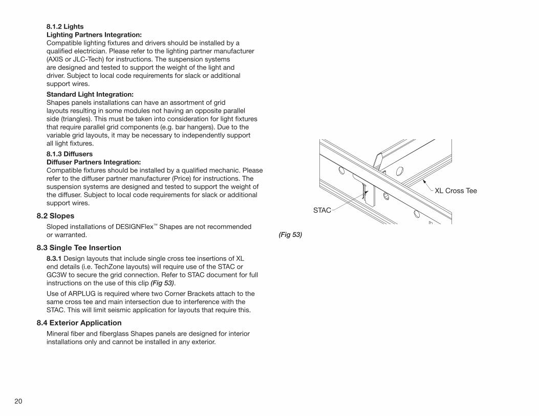
8.3 Single Tee Insertion8.3.1 Design layouts that include single cross tee insertions of XL end details (i.e. TechZone layouts) will require use of the STAC or GC3W to secure the grid connection. Refer to STAC document for full instructions on the use of this clip (Fig 53).
Use of ARPLUG is required where two Corner Brackets attach to the same cross tee and main intersection due to interference with the STAC. This will limit seismic application for layouts that require this.
8.4 Exterior Application Mineral fiber and fiberglass Shapes panels are designed for interior installations only and cannot be installed in any exterior.
STAC
XL Cross Tee
21
(Fig 54)
9. SEISMIC
9.1 General For more details on Seismic installations please see our brochure: Seismic Design: What You Need to Know.
9.2 Suspension System All seismic installations of Shapes panels must be installed per seismic design categories D, E, F due to the lack of perpendicular grid intersections. This is regardless of the total system weight. Heavy-Duty grid is required per ASTM E580 .
9.2.1 Seismic Rx Cat C, D, E and FCeiling installation should conform to basic minimums established in ASTM C636, with the following exceptions:
• Minimum 7/8" wall molding.
• Suspension system must be attached on two adjacent walls.
• Opposite walls require BERC2 and allow 3/4" movement at the wall.
• BERC2 maintains main beam and cross tee spacing; no other components required.
• BERC2 may need to be field-modified to match grid angles at the perimeter.
• Duty Rating of suspensions systems are classified per ASTM C635.
• Safety wires required on light fixtures.
• Perimeter support wires within 8" of the perimeter angle.
• Ceiling areas over 1,000 SF with back-to-back (opposing) bracket connections to the mains can be braced following standard spacing guidelines. If single bracket connections occur (no opposing bracket occupying the same rout hole) consult a professional engineer for lateral force bracing placement.
• Ceiling areas over 2,500 SF should have separation by bulkhead or partition wall.
• Ceilings without rigid bracing must have 2" oversized trim rings for sprinklers and other penetrations.
• Changes in ceiling plane must have positive bracing.
• Cable trays and electrical conduits must be independently supported and braced.
• Suspended ceilings will be subject to special inspection.
• Special bracing may be required and should be specified by the seismic engineer on the project.
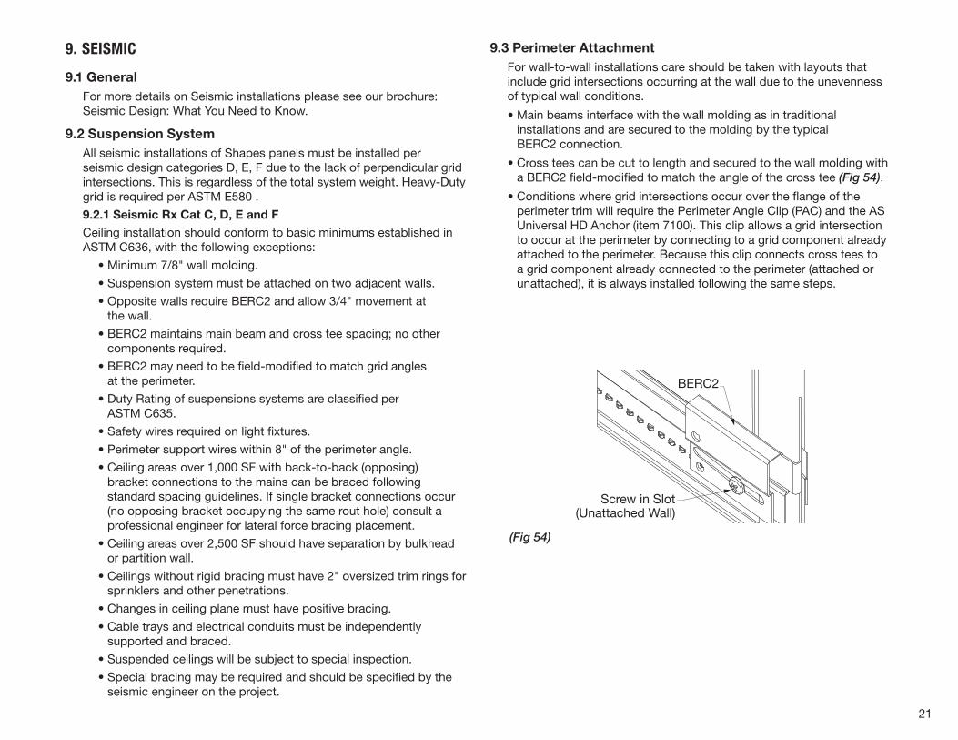
9.3 Perimeter AttachmentFor wall-to-wall installations care should be taken with layouts that include grid intersections occurring at the wall due to the unevenness of typical wall conditions.
• Main beams interface with the wall molding as in traditional installations and are secured to the molding by the typical BERC2 connection.
• Cross tees can be cut to length and secured to the wall molding with a BERC2 field-modified to match the angle of the cross tee (Fig 54).
• Conditions where grid intersections occur over the flange of the perimeter trim will require the Perimeter Angle Clip (PAC) and the AS Universal HD Anchor (item 7100). This clip allows a grid intersection to occur at the perimeter by connecting to a grid component already attached to the perimeter. Because this clip connects cross tees to a grid component already connected to the perimeter (attached or unattached), it is always installed following the same steps.
Screw in Slot(Unattached Wall)
BERC2
22
(Fig 58)
(Fig 57)
(Fig 56)
(Fig 55)
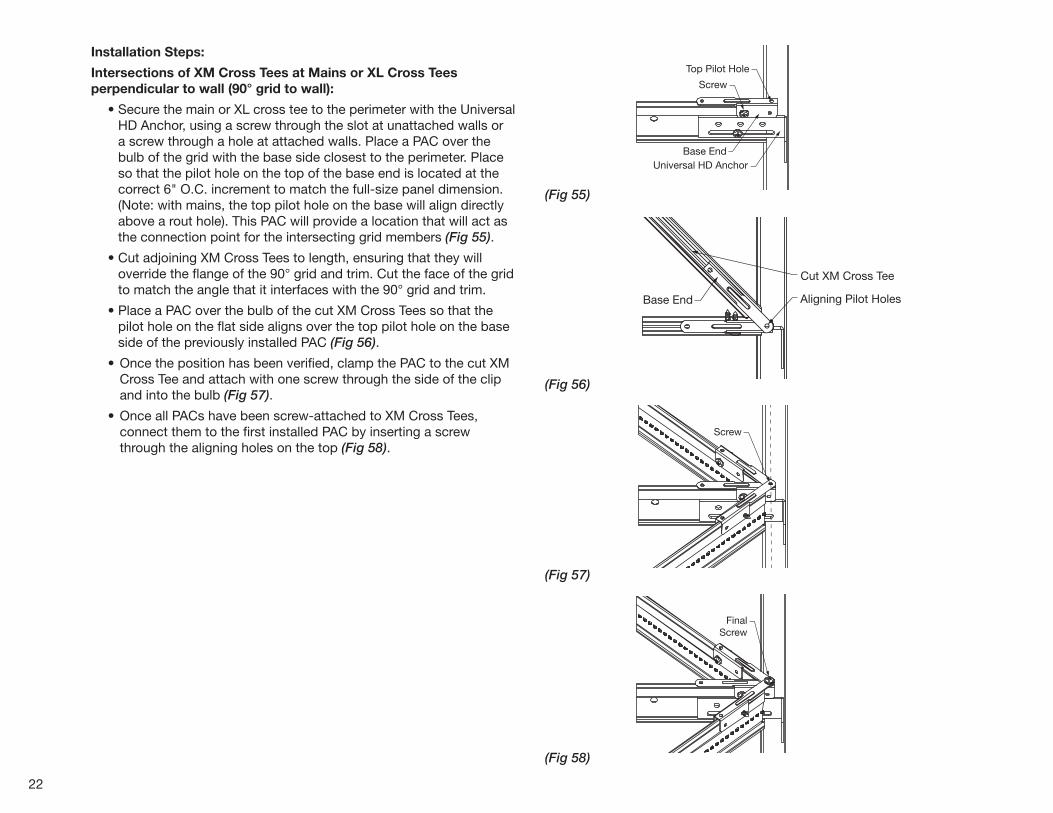
Installation Steps:
Intersections of XM Cross Tees at Mains or XL Cross Tees perpendicular to wall (90° grid to wall):
• Secure the main or XL cross tee to the perimeter with the Universal HD Anchor, using a screw through the slot at unattached walls or a screw through a hole at attached walls. Place a PAC over the bulb of the grid with the base side closest to the perimeter. Place so that the pilot hole on the top of the base end is located at the correct 6" O.C. increment to match the full-size panel dimension. (Note: with mains, the top pilot hole on the base will align directly above a rout hole). This PAC will provide a location that will act as the connection point for the intersecting grid members (Fig 55).
• Cut adjoining XM Cross Tees to length, ensuring that they will override the flange of the 90° grid and trim. Cut the face of the grid to match the angle that it interfaces with the 90° grid and trim.
• Place a PAC over the bulb of the cut XM Cross Tees so that the pilot hole on the flat side aligns over the top pilot hole on the base side of the previously installed PAC (Fig 56).
• Once the position has been verified, clamp the PAC to the cut XM Cross Tee and attach with one screw through the side of the clip and into the bulb (Fig 57).
• Once all PACs have been screw-attached to XM Cross Tees, connect them to the first installed PAC by inserting a screw through the aligning holes on the top (Fig 58).
Base EndUniversal HD Anchor
Top Pilot Hole
Screw
Base End
Base End
HD Wall Anchor
Top Pilot Hole
Aligning Pilot Holes
Cut XM Cross Tee
Screw
ScrewFinal
Screw
Base End
Base End
HD Wall Anchor
Top Pilot Hole
Aligning Pilot Holes
Cut XM Cross Tee
Screw
ScrewFinal
Screw
Base End
Base End
HD Wall Anchor
Top Pilot Hole
Aligning Pilot Holes
Cut XM Cross Tee
Screw
ScrewFinal
Screw
23
(Fig 59)
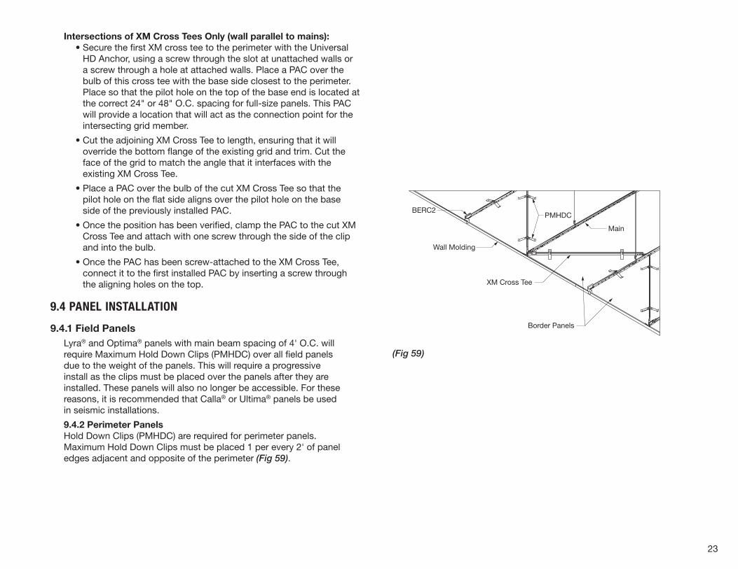
Intersections of XM Cross Tees Only (wall parallel to mains): • Secure the first XM cross tee to the perimeter with the Universal
HD Anchor, using a screw through the slot at unattached walls or a screw through a hole at attached walls. Place a PAC over the bulb of this cross tee with the base side closest to the perimeter. Place so that the pilot hole on the top of the base end is located at the correct 24" or 48" O.C. spacing for full-size panels. This PAC will provide a location that will act as the connection point for the intersecting grid member.
• Cut the adjoining XM Cross Tee to length, ensuring that it will override the bottom flange of the existing grid and trim. Cut the face of the grid to match the angle that it interfaces with the existing XM Cross Tee.
• Place a PAC over the bulb of the cut XM Cross Tee so that the pilot hole on the flat side aligns over the pilot hole on the base side of the previously installed PAC.
• Once the position has been verified, clamp the PAC to the cut XM Cross Tee and attach with one screw through the side of the clip and into the bulb.
• Once the PAC has been screw-attached to the XM Cross Tee, connect it to the first installed PAC by inserting a screw through the aligning holes on the top.
9.4 PANEL INSTALLATION
9.4.1 Field PanelsLyra® and Optima® panels with main beam spacing of 4' O.C. will require Maximum Hold Down Clips (PMHDC) over all field panels due to the weight of the panels. This will require a progressive install as the clips must be placed over the panels after they are installed. These panels will also no longer be accessible. For these reasons, it is recommended that Calla® or Ultima® panels be used in seismic installations.
9.4.2 Perimeter PanelsHold Down Clips (PMHDC) are required for perimeter panels. Maximum Hold Down Clips must be placed 1 per every 2' of panel edges adjacent and opposite of the perimeter (Fig 59).
BERC2
Wall Molding
Main
XM Cross Tee
PMHDC
Border Panels
24
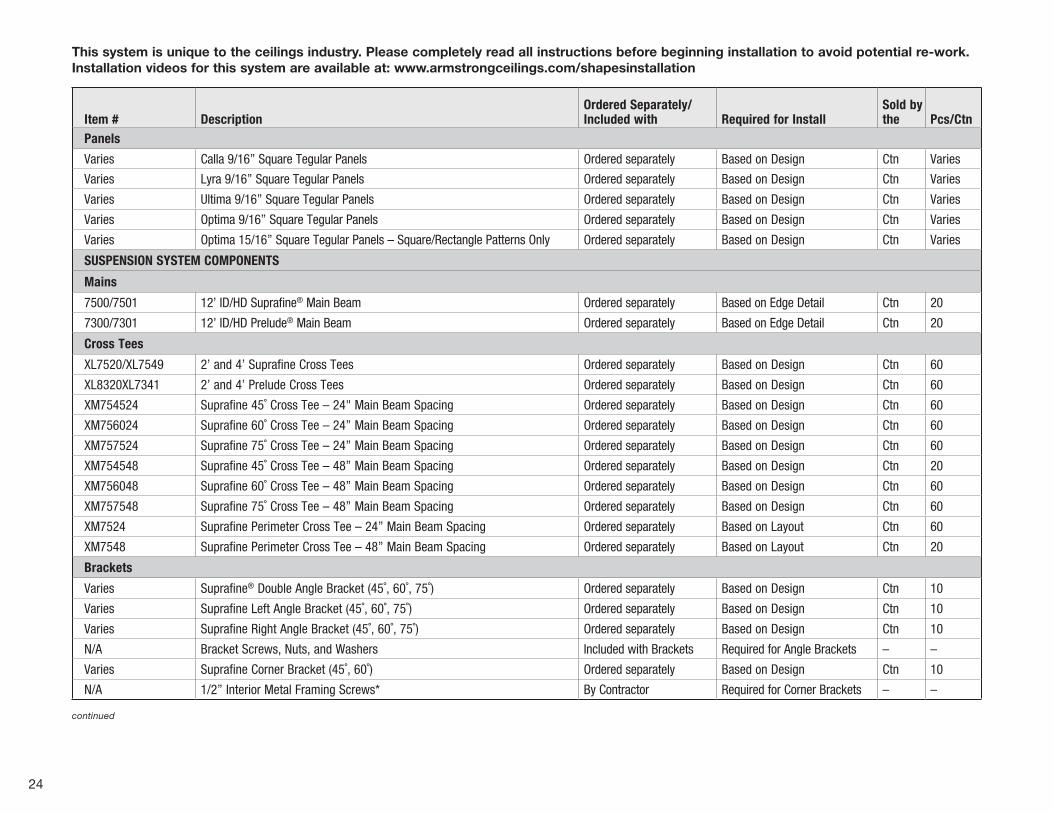
Item # DescriptionOrdered Separately/ Included with Required for Install
Sold by the Pcs/Ctn
Panels
Varies Calla 9/16” Square Tegular Panels Ordered separately Based on Design Ctn Varies
Varies Lyra 9/16” Square Tegular Panels Ordered separately Based on Design Ctn Varies
Varies Ultima 9/16” Square Tegular Panels Ordered separately Based on Design Ctn Varies
Varies Optima 9/16” Square Tegular Panels Ordered separately Based on Design Ctn Varies
Varies Optima 15/16” Square Tegular Panels – Square/Rectangle Patterns Only Ordered separately Based on Design Ctn Varies
SUSPENSION SYSTEM COMPONENTS
Mains
7500/7501 12’ ID/HD Suprafine® Main Beam Ordered separately Based on Edge Detail Ctn 20
7300/7301 12’ ID/HD Prelude® Main Beam Ordered separately Based on Edge Detail Ctn 20
Cross Tees
XL7520/XL7549 2’ and 4’ Suprafine Cross Tees Ordered separately Based on Design Ctn 60
XL8320XL7341 2’ and 4’ Prelude Cross Tees Ordered separately Based on Design Ctn 60
XM754524 Suprafine 45˚ Cross Tee – 24" Main Beam Spacing Ordered separately Based on Design Ctn 60
XM756024 Suprafine 60˚ Cross Tee – 24” Main Beam Spacing Ordered separately Based on Design Ctn 60
XM757524 Suprafine 75˚ Cross Tee – 24” Main Beam Spacing Ordered separately Based on Design Ctn 60
XM754548 Suprafine 45˚ Cross Tee – 48” Main Beam Spacing Ordered separately Based on Design Ctn 20
XM756048 Suprafine 60˚ Cross Tee – 48” Main Beam Spacing Ordered separately Based on Design Ctn 60
XM757548 Suprafine 75˚ Cross Tee – 48” Main Beam Spacing Ordered separately Based on Design Ctn 60
XM7524 Suprafine Perimeter Cross Tee – 24” Main Beam Spacing Ordered separately Based on Layout Ctn 60
XM7548 Suprafine Perimeter Cross Tee – 48” Main Beam Spacing Ordered separately Based on Layout Ctn 20
Brackets
Varies Suprafine® Double Angle Bracket (45˚, 60˚, 75˚) Ordered separately Based on Design Ctn 10
Varies Suprafine Left Angle Bracket (45˚, 60˚, 75˚) Ordered separately Based on Design Ctn 10
Varies Suprafine Right Angle Bracket (45˚, 60˚, 75˚) Ordered separately Based on Design Ctn 10
N/A Bracket Screws, Nuts, and Washers Included with Brackets Required for Angle Brackets – –
Varies Suprafine Corner Bracket (45˚, 60˚) Ordered separately Based on Design Ctn 10
N/A 1/2” Interior Metal Framing Screws* By Contractor Required for Corner Brackets – –
continued
This system is unique to the ceilings industry. Please completely read all instructions before beginning installation to avoid potential re-work. Installation videos for this system are available at: www.armstrongceilings.com/shapesinstallation
25
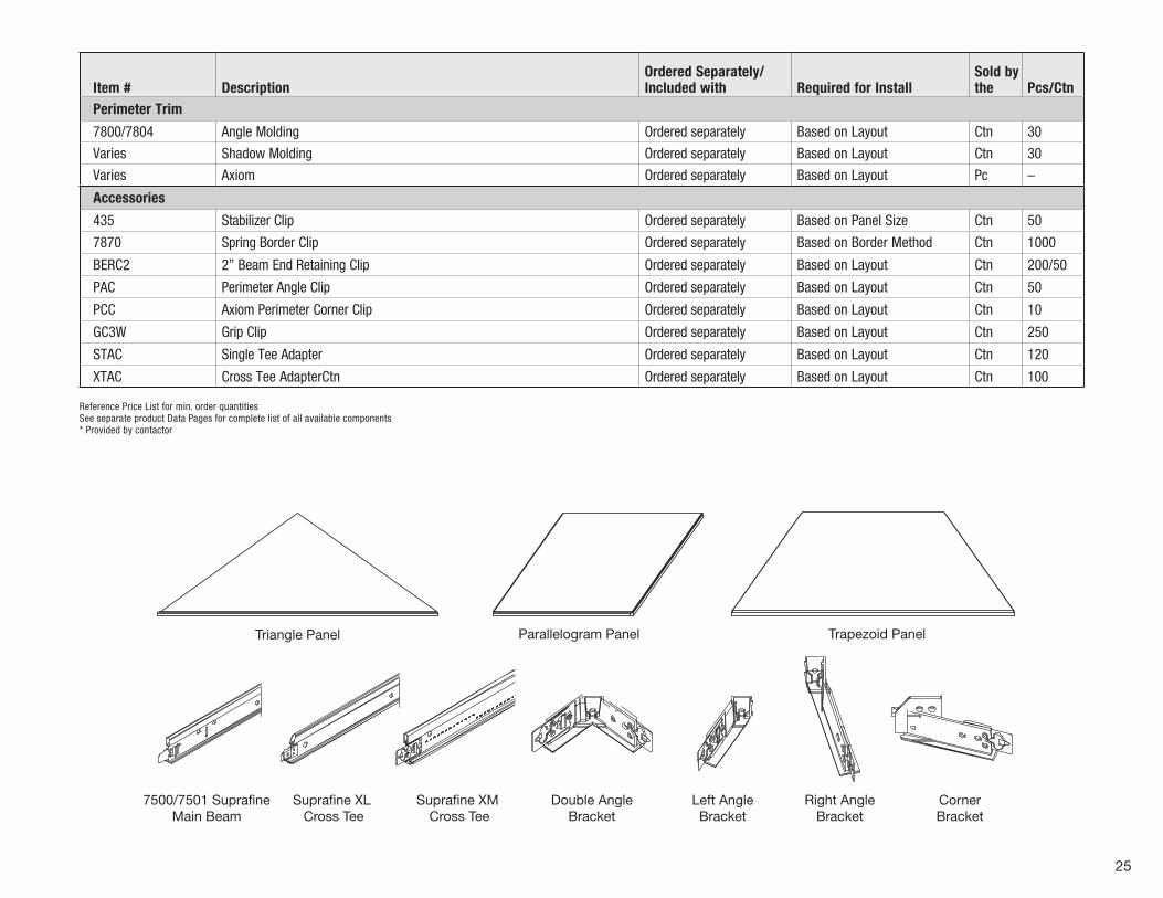
Item # DescriptionOrdered Separately/ Included with Required for Install
Sold by the Pcs/Ctn
Perimeter Trim
7800/7804 Angle Molding Ordered separately Based on Layout Ctn 30
Varies Shadow Molding Ordered separately Based on Layout Ctn 30
Varies Axiom Ordered separately Based on Layout Pc –
Accessories
435 Stabilizer Clip Ordered separately Based on Panel Size Ctn 50
7870 Spring Border Clip Ordered separately Based on Border Method Ctn 1000
BERC2 2” Beam End Retaining Clip Ordered separately Based on Layout Ctn 200/50
PAC Perimeter Angle Clip Ordered separately Based on Layout Ctn 50
PCC Axiom Perimeter Corner Clip Ordered separately Based on Layout Ctn 10
GC3W Grip Clip Ordered separately Based on Layout Ctn 250
STAC Single Tee Adapter Ordered separately Based on Layout Ctn 120
XTAC Cross Tee AdapterCtn Ordered separately Based on Layout Ctn 100
Reference Price List for min. order quantities See separate product Data Pages for complete list of all available components * Provided by contactor
Triangle Panel
7500/7501 Supra neMain Beam
Supra ne XL Cross Tee
Supra ne XM Cross Tee
Double AngleBracket
Left AngleBracket
Right AngleBracket
CornerBracket
BERC2 Spring BorderClip 7870
StabilizerClip 435
PMHDC
Single TeeAdapter (STAC)
Grip Clip (GC3W) Cross TeeAdapter (XTAC)
Perimeter AngleClip (PAC)
Perimeter CornerClip (PCC)
Screw and NutAssembly
Parallelogram Panel Trapezoid Panel
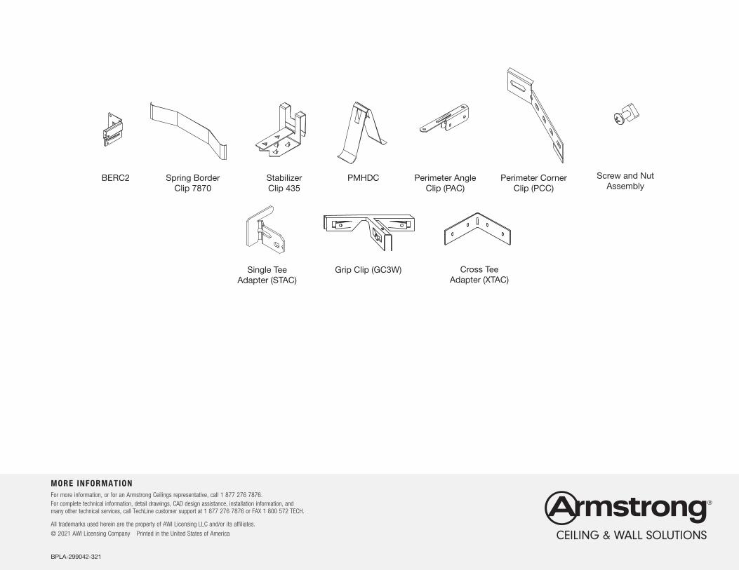
MORE INFORMATIONFor more information, or for an Armstrong Ceilings representative, call 1 877 276 7876.For complete technical information, detail drawings, CAD design assistance, installation information, and many other technical services, call TechLine customer support at 1 877 276 7876 or FAX 1 800 572 TECH.
All trademarks used herein are the property of AWI Licensing LLC and/or its affiliates.
© 2021 AWI Licensing Company Printed in the United States of America
BPLA-299042-321
Triangle Panel
7500/7501 Supra neMain Beam
Supra ne XL Cross Tee
Supra ne XM Cross Tee
Double AngleBracket
Left AngleBracket
Right AngleBracket
CornerBracket
BERC2 Spring BorderClip 7870
StabilizerClip 435
PMHDC
Single TeeAdapter (STAC)
Grip Clip (GC3W) Cross TeeAdapter (XTAC)
Perimeter AngleClip (PAC)
Perimeter CornerClip (PCC)
Screw and NutAssembly
Parallelogram Panel Trapezoid Panel