Embed Size (px)
Citation preview
OPTIMUMM A S C H I N E N - G E R M A N Y
© 2
007
GB
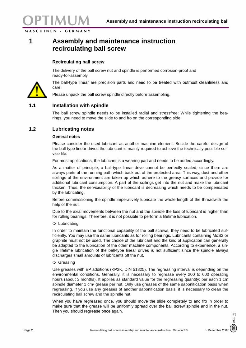
Assembly and maintenance instruction
Version 2.0BF20/ BF20L
Recirculating ball screw
Keep for future reference!
5. Dezember 2007 Page 1Recirculating ball screw assembly and maintenance instruction ; Version 2.0
Assembly and maintenance instruction recirculating ballOPTIMUMM A S C H I N E N - G E R M A N Y
© 2007
G
1 Assembly and maintenance instruction recirculating ball screw
Recirculating ball screw
The delivery of the ball screw nut and spindle is performed corrosion-proof and ready-for-assembly.
The ball-type linear are precision parts and need to be treated with outmost cleanliness andcare.
Please unpack the ball screw spindle directly before assembling.
1.1 Installation with spindleThe ball screw spindle needs to be installed radial and stressfree: While tightening the bea-rings, you need to move the slide to and fro on the corresponding side.
1.2 Lubricating notesGeneral notesPlease consider the used lubricant as another machine element. Beside the careful design ofthe ball-type linear drives the lubricant is mainly required to achieve the technically possible ser-vice life.
For most applications, the lubricant is a wearing part and needs to be added accordingly.
As a matter of principle, a ball-type linear drive cannot be perfectly sealed, since there arealways parts of the running path which back out of the protected area. This way, dust and othersoilings of the environment are taken up which adhere to the greasy surfaces and provide foradditional lubricant consumption. A part of the soilings get into the nut and make the lubricantthicken. Thus, the serviceability of the lubricant is decreasing which needs to be compensatedby the lubricating.
Before commissioning the spindle imperatively lubricate the whole length of the threadwith thehelp of the nut.
Due to the axial movements between the nut and the spindle the loss of lubricant is higher thanfor rolling bearings. Therefore, it is not possible to perform a lifetime lubrication.
Lubricating
In order to maintain the functional capability of the ball screws, they need to be lubricated suf-ficiently. You may use the same lubricants as for rolling bearings. Lubricants containing MoS2 orgraphite must not be used. The choice of the lubricant and the kind of application can generallybe adapted to the lubrication of the other machine components. According to experience, a sin-gle lifetime lubrication of the ball-type linear drives is not sufficient since the spindle alwaysdischarges small amounts of lubricants off the nut.
Greasing
Use greases with EP additions (KP2K, DIN 51825). The regreasing interval is depending on theenvironmental conditions. Generally, it is necessary to regrease every 200 to 600 operatinghours (about 3 months). It applies as standard value for the regreasing quantity: per each 1 cmspindle diameter 1 cm³ grease per nut. Only use greases of the same saponification basis whenregreasing. If you use any greases of another saponification basis, it is necessary to clean therecirculating ball screw and the spindle nut.
When you have regreased once, you should move the slide completely to and fro in order tomake sure that the grease will be uniformly spread over the ball screw spindle and in the nut.Then you should regrease once again.
5. Dezember 2007Page 2 Recirculating ball screw assembly and maintenance instruction ; Version 2.0
B
OPTIMUMM A S C H I N E N - G E R M A N Y
Assembly and maintenance instruction recirculating ball screw
© 2
007
GB
1.2.1 Greases
This list is a recommendation without engagement.
1.3 Notes regarding the storageBall-type linear drives are susceptible to damages and soiling. They need to be stored at a dryplace. The spindle needs to be supported in a way that it cannot bend.
Protect the lubricated ball-linear drive from dust and chips.
1.4 Technical data
Lubricant Classification Quality Manufacturer / Type Quan-tity
Multi-purpose grease on mineral
oil basisNLGI 3 K2K according to
DIN 51825
AralMulti-purpose grease HL3
2-3 cm³
FuchsMulti-purpose grease
FWA 220
BPEnergr. LS3
ShellRetinax AAlvania R3
KlüberIsoflex NBU 15
OptimolOptitemp TT1
Recirculating ball screw Pitch Tolerance class Tolerance of deviation about 300 mm
travel
X-axis 4
IT7 52 µmY-axis 4
Z-axis 5
5. Dezember 2007 Page 3Recirculating ball screw assembly and maintenance instruction ; Version 2.0
Assembly and maintenance instruction recirculating ballOPTIMUMM A S C H I N E N - G E R M A N Y
© 2007
G
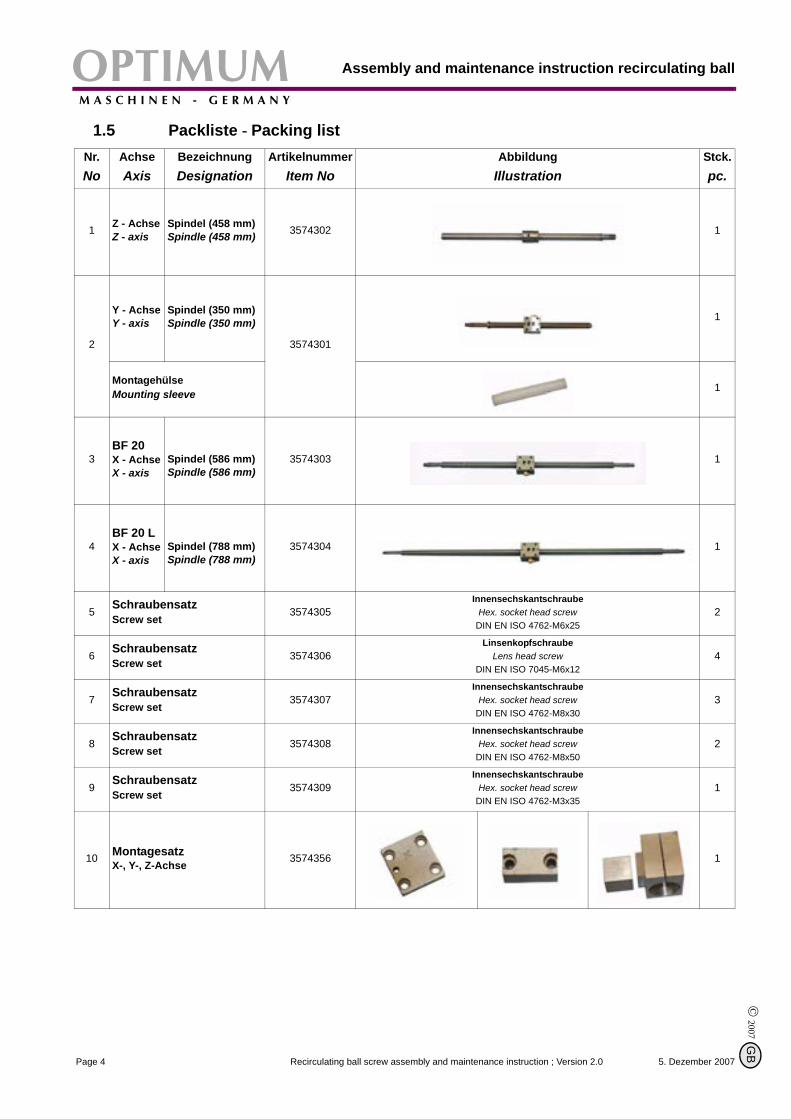
1.5 Packliste - Packing listNr.No
AchseAxis
BezeichnungDesignation
ArtikelnummerItem No
AbbildungIllustration
Stck.pc.
1 Z - AchseZ - axis
Spindel (458 mm)Spindle (458 mm) 3574302 1
2
Y - AchseY - axis
Spindel (350 mm)Spindle (350 mm)
3574301
1
MontagehülseMounting sleeve 1
3BF 20X - AchseX - axis
Spindel (586 mm)Spindle (586 mm)
3574303 1
4BF 20 LX - AchseX - axis
Spindel (788 mm)Spindle (788 mm)
3574304 1
5 SchraubensatzScrew set
3574305Innensechskantschraube
Hex. socket head screwDIN EN ISO 4762-M6x25
2
6 SchraubensatzScrew set
3574306Linsenkopfschraube
Lens head screwDIN EN ISO 7045-M6x12
4
7 SchraubensatzScrew set
3574307Innensechskantschraube
Hex. socket head screwDIN EN ISO 4762-M8x30
3
8SchraubensatzScrew set
3574308Innensechskantschraube
Hex. socket head screwDIN EN ISO 4762-M8x50
2
9SchraubensatzScrew set
3574309Innensechskantschraube
Hex. socket head screwDIN EN ISO 4762-M3x35
1
10 MontagesatzX-, Y-, Z-Achse 3574356 1
5. Dezember 2007Page 4 Recirculating ball screw assembly and maintenance instruction ; Version 2.0
B
OPTIMUMM A S C H I N E N - G E R M A N Y
Assembly and maintenance instruction recirculating ball screw
© 2
007
GB
1.6 Converting to a recirculating ball screw
INFORMATION
When assembling the BF20 and BF20L from trapezoidal threads to recirculating ball screws, it ispossible that the travels of the X-, Y- and Z-axis are changing.
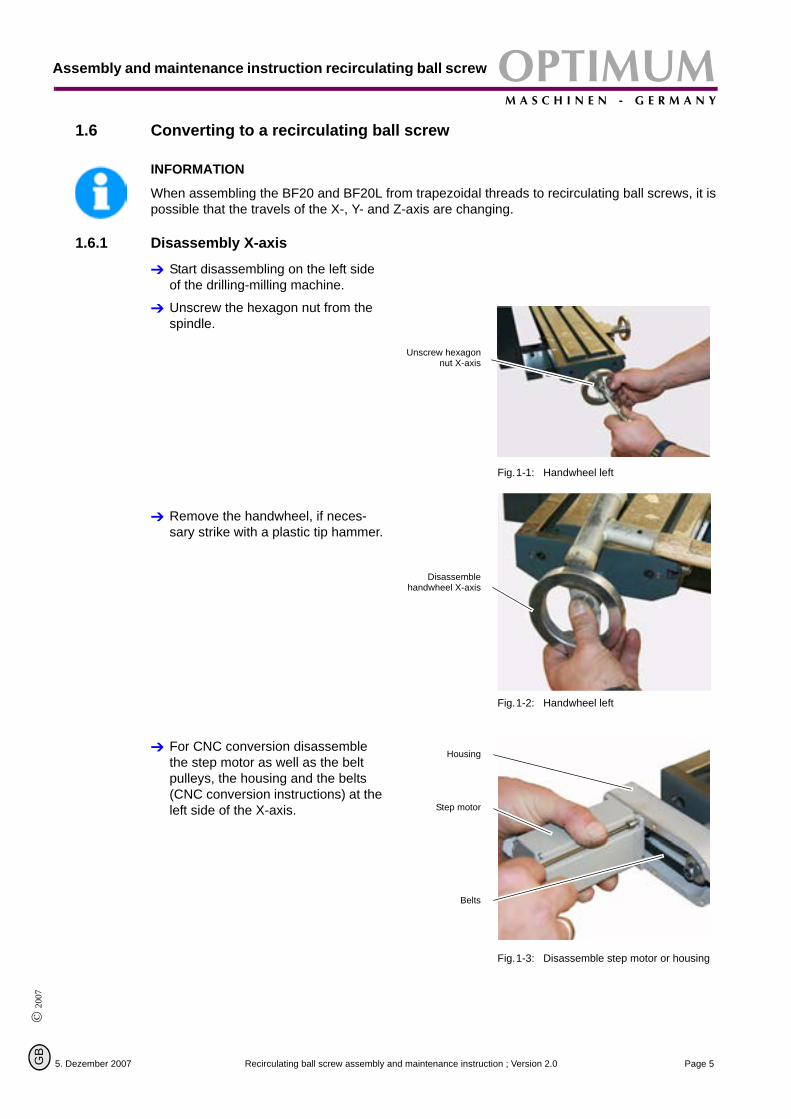
1.6.1 Disassembly X-axis
Start disassembling on the left side of the drilling-milling machine.
Unscrew the hexagon nut from the spindle.
Fig.1-1: Handwheel left
Remove the handwheel, if neces-sary strike with a plastic tip hammer.
Fig.1-2: Handwheel left
For CNC conversion disassemble the step motor as well as the belt pulleys, the housing and the belts (CNC conversion instructions) at the left side of the X-axis.
Fig.1-3: Disassemble step motor or housing
Unscrew hexagonnut X-axis
Disassemblehandwheel X-axis
Housing
Step motor
Belts
5. Dezember 2007 Page 5Recirculating ball screw assembly and maintenance instruction ; Version 2.0
Assembly and maintenance instruction recirculating ballOPTIMUMM A S C H I N E N - G E R M A N Y
© 2007
G
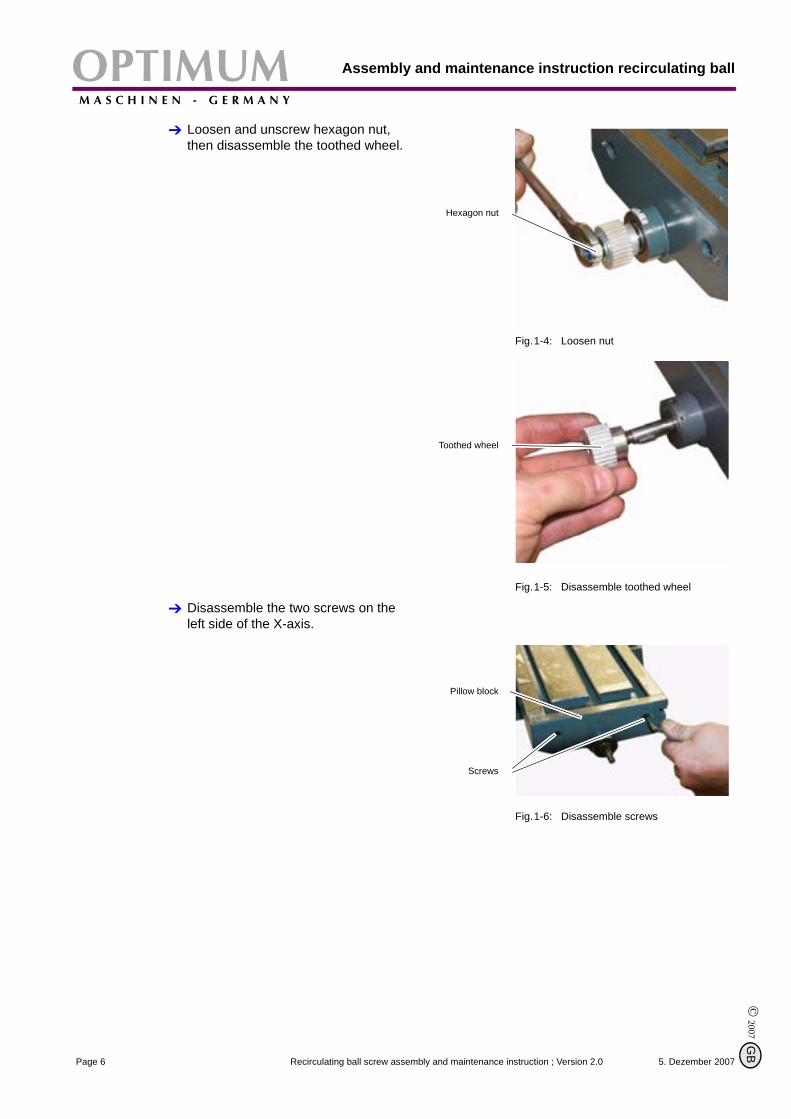
Loosen and unscrew hexagon nut, then disassemble the toothed wheel.
Fig.1-4: Loosen nut
Fig.1-5: Disassemble toothed wheel
Disassemble the two screws on the left side of the X-axis.
Fig.1-6: Disassemble screws
Hexagon nut
Toothed wheel
Pillow block
Screws
5. Dezember 2007Page 6 Recirculating ball screw assembly and maintenance instruction ; Version 2.0
B
OPTIMUMM A S C H I N E N - G E R M A N Y
Assembly and maintenance instruction recirculating ball screw
© 2
007
GB
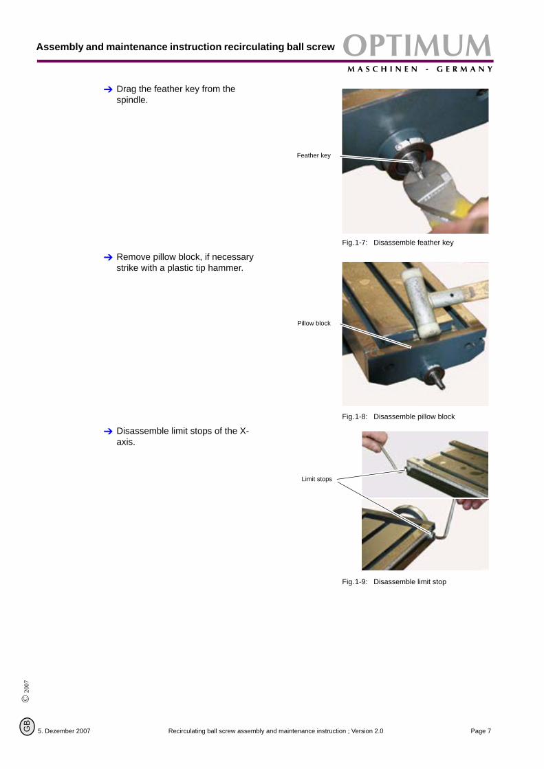
Drag the feather key from the spindle.
Fig.1-7: Disassemble feather key
Remove pillow block, if necessary strike with a plastic tip hammer.
Fig.1-8: Disassemble pillow block
Disassemble limit stops of the X-axis.
Fig.1-9: Disassemble limit stop
Feather key
Pillow block
Limit stops
5. Dezember 2007 Page 7Recirculating ball screw assembly and maintenance instruction ; Version 2.0
Assembly and maintenance instruction recirculating ballOPTIMUMM A S C H I N E N - G E R M A N Y
© 2007
G
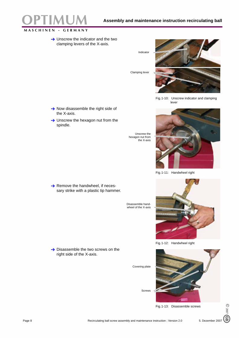
Unscrew the indicator and the two clamping levers of the X-axis.
Fig.1-10: Unscrew indicator and clamping lever
Now disassemble the right side of the X-axis.
Unscrew the hexagon nut from the spindle.
Fig.1-11: Handwheel right
Remove the handwheel, if neces-sary strike with a plastic tip hammer.
Fig.1-12: Handwheel right
Disassemble the two screws on the right side of the X-axis.
Fig.1-13: Disassemble screws
Indicator
Clamping lever
Unscrew thehexagon nut from
the X-axis
Disassemble hand-wheel of the X-axis
Covering plate
Screws
5. Dezember 2007Page 8 Recirculating ball screw assembly and maintenance instruction ; Version 2.0
B
OPTIMUMM A S C H I N E N - G E R M A N Y
Assembly and maintenance instruction recirculating ball screw
© 2
007
GB
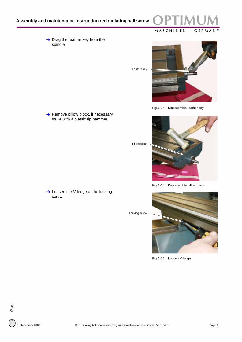
Drag the feather key from the spindle.
Fig.1-14: Disassemble feather key
Remove pillow block, if necessary strike with a plastic tip hammer.
Fig.1-15: Disassemble pillow block
Loosen the V-ledge at the locking screw.
Fig.1-16: Loosen V-ledge
Feather key
Pillow block
Locking screw
5. Dezember 2007 Page 9Recirculating ball screw assembly and maintenance instruction ; Version 2.0
Assembly and maintenance instruction recirculating ballOPTIMUMM A S C H I N E N - G E R M A N Y
© 2007
G
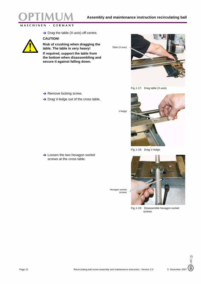
Drag the table (X-axis) off-centre.
CAUTION!Risk of crushing when dragging the table. The table is very heavy!If required, support the table from the bottom when disassembling and secure it against falling down.
Fig.1-17: Drag table (X-axis)
Remove locking screw.
Drag V-ledge out of the cross table.
Fig.1-18: Drag V-ledge
Loosen the two hexagon socket screws at the cross table.
Fig.1-19: Disassemble hexagon socket screws
Table (X-axis)
V-ledge
Hexagon socketscrews
5. Dezember 2007Page 10 Recirculating ball screw assembly and maintenance instruction ; Version 2.0
B
OPTIMUMM A S C H I N E N - G E R M A N Y
Assembly and maintenance instruction recirculating ball screw
© 2
007
GB
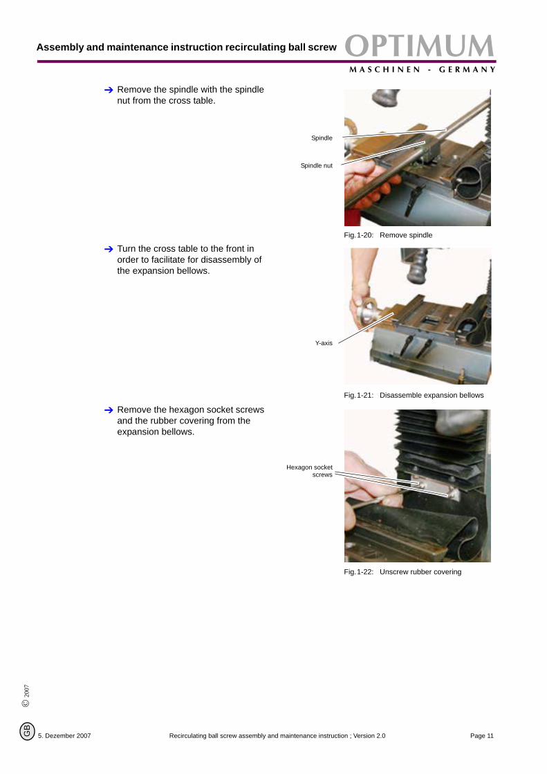
Remove the spindle with the spindle nut from the cross table.
Fig.1-20: Remove spindle
Turn the cross table to the front in order to facilitate for disassembly of the expansion bellows.
Fig.1-21: Disassemble expansion bellows
Remove the hexagon socket screws and the rubber covering from the expansion bellows.
Fig.1-22: Unscrew rubber covering
Spindle
Spindle nut
Y-axis
Hexagon socketscrews
5. Dezember 2007 Page 11Recirculating ball screw assembly and maintenance instruction ; Version 2.0
Assembly and maintenance instruction recirculating ballOPTIMUMM A S C H I N E N - G E R M A N Y
© 2007
G
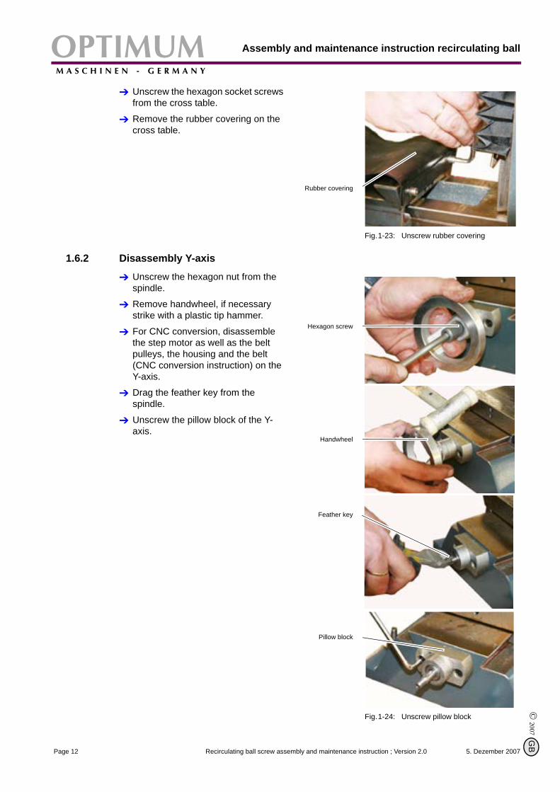
Unscrew the hexagon socket screws from the cross table.
Remove the rubber covering on the cross table.
Fig.1-23: Unscrew rubber covering
1.6.2 Disassembly Y-axis
Unscrew the hexagon nut from the spindle.
Remove handwheel, if necessary strike with a plastic tip hammer.
For CNC conversion, disassemble the step motor as well as the belt pulleys, the housing and the belt (CNC conversion instruction) on the Y-axis.
Drag the feather key from the spindle.
Unscrew the pillow block of the Y-axis.
Fig.1-24: Unscrew pillow block
Rubber covering
Hexagon screw
Handwheel
Feather key
Pillow block
5. Dezember 2007Page 12 Recirculating ball screw assembly and maintenance instruction ; Version 2.0
B
OPTIMUMM A S C H I N E N - G E R M A N Y
Assembly and maintenance instruction recirculating ball screw
© 2
007
GB
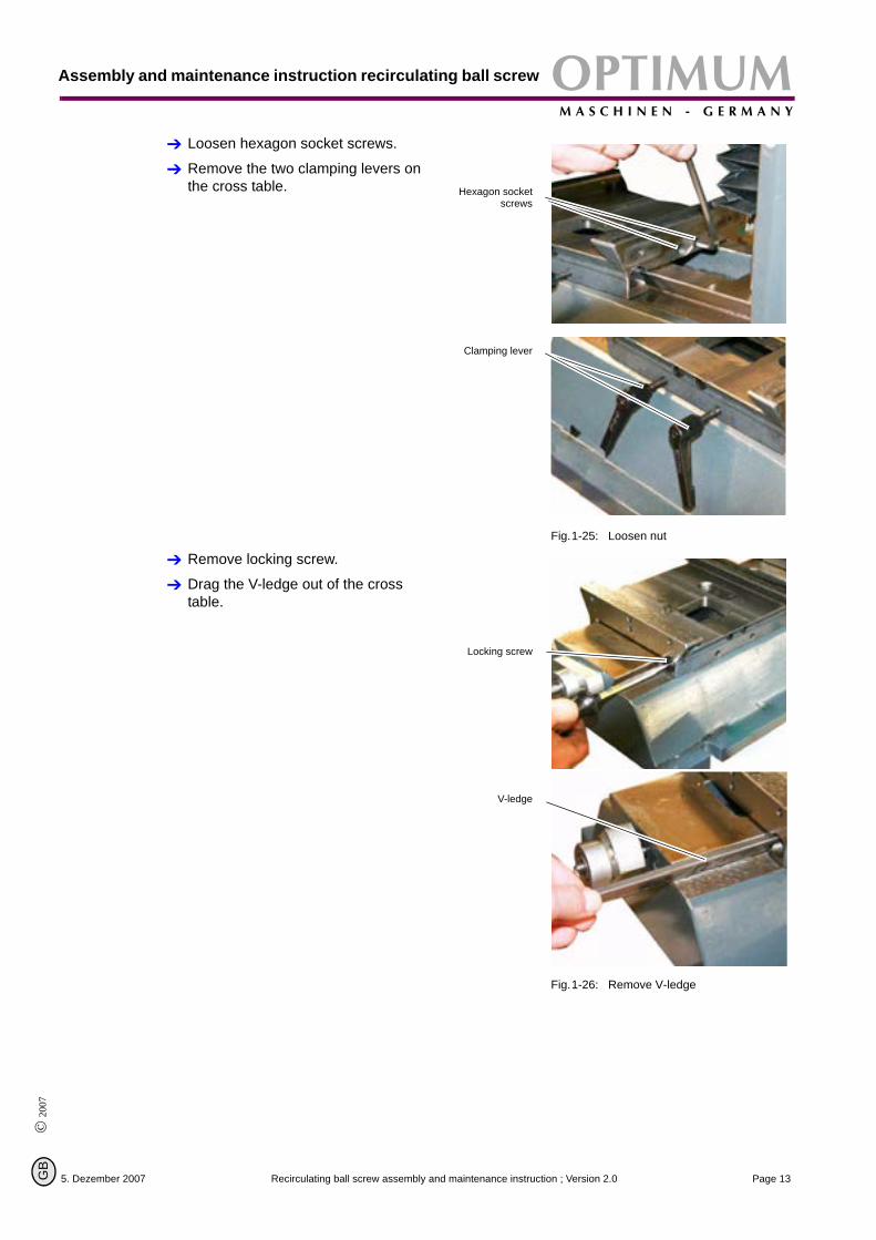
Loosen hexagon socket screws.
Remove the two clamping levers on the cross table.
Fig.1-25: Loosen nut
Remove locking screw.
Drag the V-ledge out of the cross table.
Fig.1-26: Remove V-ledge
Hexagon socketscrews
Clamping lever
Locking screw
V-ledge
5. Dezember 2007 Page 13Recirculating ball screw assembly and maintenance instruction ; Version 2.0
Assembly and maintenance instruction recirculating ballOPTIMUMM A S C H I N E N - G E R M A N Y
© 2007
G
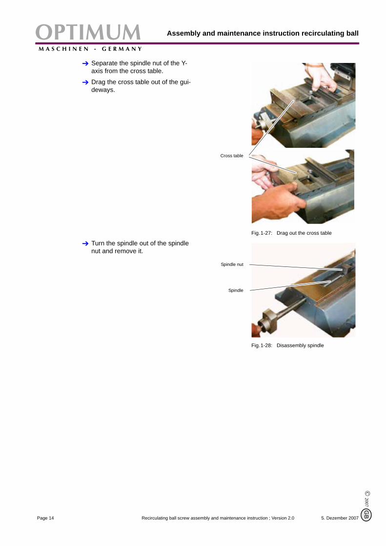
Separate the spindle nut of the Y-axis from the cross table.
Drag the cross table out of the gui-deways.
Fig.1-27: Drag out the cross table
Turn the spindle out of the spindle nut and remove it.
Fig.1-28: Disassembly spindle
Cross table
Spindle nut
Spindle
5. Dezember 2007Page 14 Recirculating ball screw assembly and maintenance instruction ; Version 2.0
B
OPTIMUMM A S C H I N E N - G E R M A N Y
Assembly and maintenance instruction recirculating ball screw
© 2
007
GB
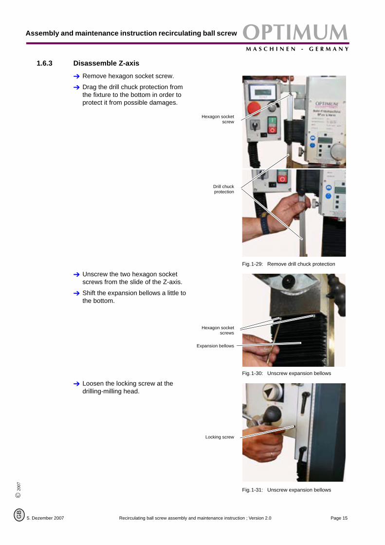
1.6.3 Disassemble Z-axis
Remove hexagon socket screw.
Drag the drill chuck protection from the fixture to the bottom in order to protect it from possible damages.
Fig.1-29: Remove drill chuck protection
Unscrew the two hexagon socket screws from the slide of the Z-axis.
Shift the expansion bellows a little to the bottom.
Fig.1-30: Unscrew expansion bellows
Loosen the locking screw at the drilling-milling head.
Fig.1-31: Unscrew expansion bellows
Hexagon socketscrew
Drill chuckprotection
Hexagon socketscrews
Expansion bellows
Locking screw
5. Dezember 2007 Page 15Recirculating ball screw assembly and maintenance instruction ; Version 2.0
Assembly and maintenance instruction recirculating ballOPTIMUMM A S C H I N E N - G E R M A N Y
© 2007
G
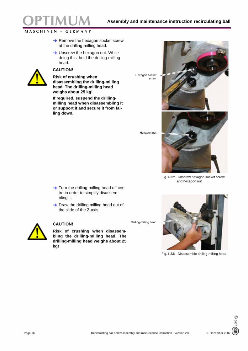
Remove the hexagon socket screw at the drilling-milling head.
Unscrew the hexagon nut. While doing this, hold the drilling-milling head.
CAUTION!Risk of crushing when disassembling the drilling-milling head. The drilling-milling head weighs about 25 kg!If required, suspend the drilling-milling head when disassembling it or support it and secure it from fal-ling down.
Fig.1-32: Unscrew hexagon socket screw and hexagon nut
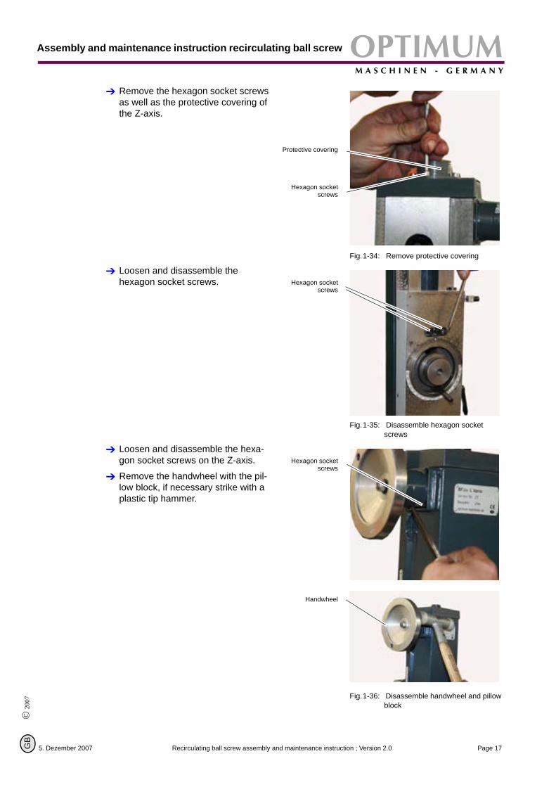
Turn the drilling-milling head off cen-tre in order to simplify disassem-bling it.
Draw the drilling milling head out of the slide of the Z-axis.
CAUTION!Risk of crushing when disassem-bling the drilling-milling head. Thedrilling-milling head weighs about 25kg!
Fig.1-33: Disassemble drilling-milling head
Hexagon socketscrew
Hexagon nut
Drilling-milling head
5. Dezember 2007Page 16 Recirculating ball screw assembly and maintenance instruction ; Version 2.0
B
OPTIMUMM A S C H I N E N - G E R M A N Y
Assembly and maintenance instruction recirculating ball screw
© 2
007
GB
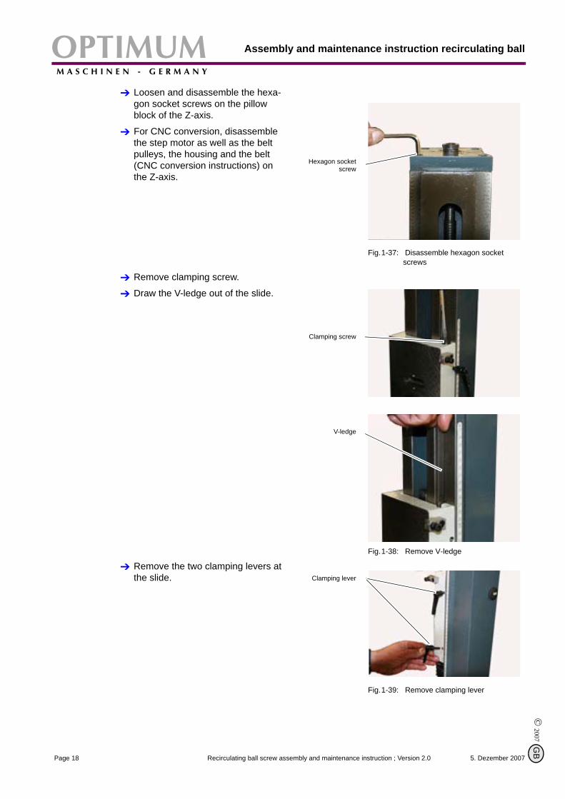
Remove the hexagon socket screws as well as the protective covering of the Z-axis.
Fig.1-34: Remove protective covering
Loosen and disassemble the hexagon socket screws.
Fig.1-35: Disassemble hexagon socket screws
Loosen and disassemble the hexa-gon socket screws on the Z-axis.
Remove the handwheel with the pil-low block, if necessary strike with a plastic tip hammer.
Fig.1-36: Disassemble handwheel and pillow block
Protective covering
Hexagon socketscrews
Hexagon socketscrews
Hexagon socketscrews
Handwheel
5. Dezember 2007 Page 17Recirculating ball screw assembly and maintenance instruction ; Version 2.0
Assembly and maintenance instruction recirculating ballOPTIMUMM A S C H I N E N - G E R M A N Y
© 2007
G
Loosen and disassemble the hexa-gon socket screws on the pillow block of the Z-axis.
For CNC conversion, disassemble the step motor as well as the belt pulleys, the housing and the belt (CNC conversion instructions) on the Z-axis.
Fig.1-37: Disassemble hexagon socket screws
Remove clamping screw.
Draw the V-ledge out of the slide.
Fig.1-38: Remove V-ledge
Remove the two clamping levers at the slide.
Fig.1-39: Remove clamping lever
Hexagon socketscrew
Clamping screw
V-ledge
Clamping lever
5. Dezember 2007Page 18 Recirculating ball screw assembly and maintenance instruction ; Version 2.0
B
OPTIMUMM A S C H I N E N - G E R M A N Y
Assembly and maintenance instruction recirculating ball screw
© 2
007
GB
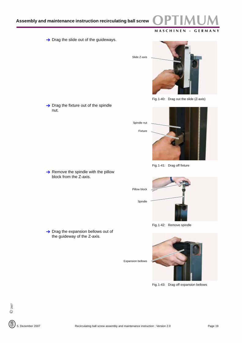
Drag the slide out of the guideways.
Fig.1-40: Drag out the slide (Z-axis)
Drag the fixture out of the spindle nut.
Fig.1-41: Drag off fixture
Remove the spindle with the pillow block from the Z-axis.
Fig.1-42: Remove spindle
Drag the expansion bellows out of the guideway of the Z-axis.
Fig.1-43: Drag off expansion bellows
Slide Z-axis
Spindle nut
Fixture
Pillow block
Spindle
Expansion bellows
5. Dezember 2007 Page 19Recirculating ball screw assembly and maintenance instruction ; Version 2.0
Assembly and maintenance instruction recirculating ballOPTIMUMM A S C H I N E N - G E R M A N Y
© 2007
G
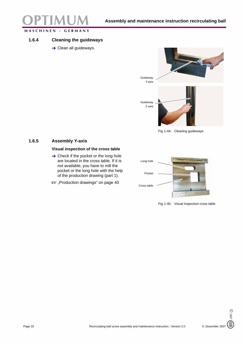
1.6.4 Cleaning the guideways
Clean all guideways.
Fig.1-44: Cleaning guideways
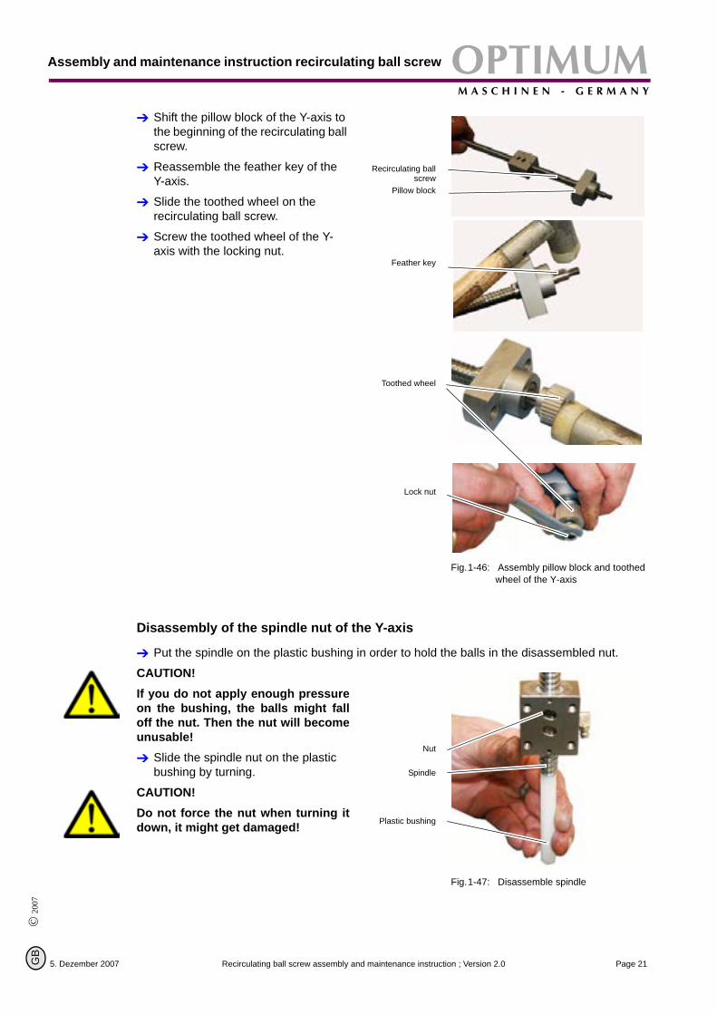
1.6.5 Assembly Y-axis
Visual inspection of the cross tableCheck if the pocket or the long hole are located in the cross table. If it is not available, you have to mill the pocket or the long hole with the help of the production drawing (part 1).
„Production drawings“ on page 40
Fig.1-45: Visual inspection cross table
GuidewayY-axis
GuidewayZ-axis
Long hole
Cross table
5. Dezember 2007Page 20 Recirculating ball screw assembly and maintenance instruction ; Version 2.0
B
OPTIMUMM A S C H I N E N - G E R M A N Y
Assembly and maintenance instruction recirculating ball screw
© 2
007
GB
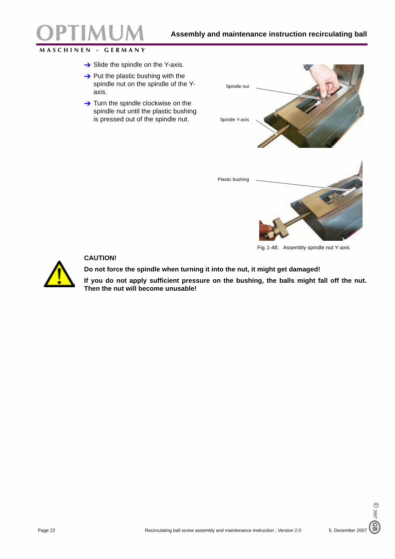
Shift the pillow block of the Y-axis to the beginning of the recirculating ball screw.
Reassemble the feather key of the Y-axis.
Slide the toothed wheel on the recirculating ball screw.
Screw the toothed wheel of the Y-axis with the locking nut.
Fig.1-46: Assembly pillow block and toothed wheel of the Y-axis
Disassembly of the spindle nut of the Y-axis
Put the spindle on the plastic bushing in order to hold the balls in the disassembled nut.
CAUTION!If you do not apply enough pressureon the bushing, the balls might falloff the nut. Then the nut will becomeunusable!
Slide the spindle nut on the plastic bushing by turning.
CAUTION!Do not force the nut when turning itdown, it might get damaged!
Fig.1-47: Disassemble spindle
Recirculating ballscrew
Pillow block
Feather key
Toothed wheel
Lock nut
Nut
Spindle
Plastic bushing
5. Dezember 2007 Page 21Recirculating ball screw assembly and maintenance instruction ; Version 2.0
Assembly and maintenance instruction recirculating ballOPTIMUMM A S C H I N E N - G E R M A N Y
© 2007
G
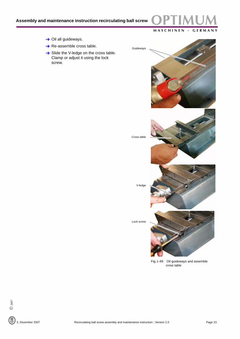
Slide the spindle on the Y-axis.
Put the plastic bushing with the spindle nut on the spindle of the Y-axis.
Turn the spindle clockwise on the spindle nut until the plastic bushing is pressed out of the spindle nut.
Fig.1-48: Assembly spindle nut Y-axis
CAUTION!Do not force the spindle when turning it into the nut, it might get damaged!If you do not apply sufficient pressure on the bushing, the balls might fall off the nut.Then the nut will become unusable!
Spindle nut
Spindle Y-axis
Plastic bushing
5. Dezember 2007Page 22 Recirculating ball screw assembly and maintenance instruction ; Version 2.0
B
OPTIMUMM A S C H I N E N - G E R M A N Y
Assembly and maintenance instruction recirculating ball screw
© 2
007
GB
Oil all guideways.
Re-assemble cross table.
Slide the V-ledge on the cross table. Clamp or adjust it using the lock screw.
Fig.1-49: Oil guideways and assemble cross table
Guideways
Cross table
V-ledge
Lock screw
5. Dezember 2007 Page 23Recirculating ball screw assembly and maintenance instruction ; Version 2.0
Assembly and maintenance instruction recirculating ballOPTIMUMM A S C H I N E N - G E R M A N Y
© 2007
G
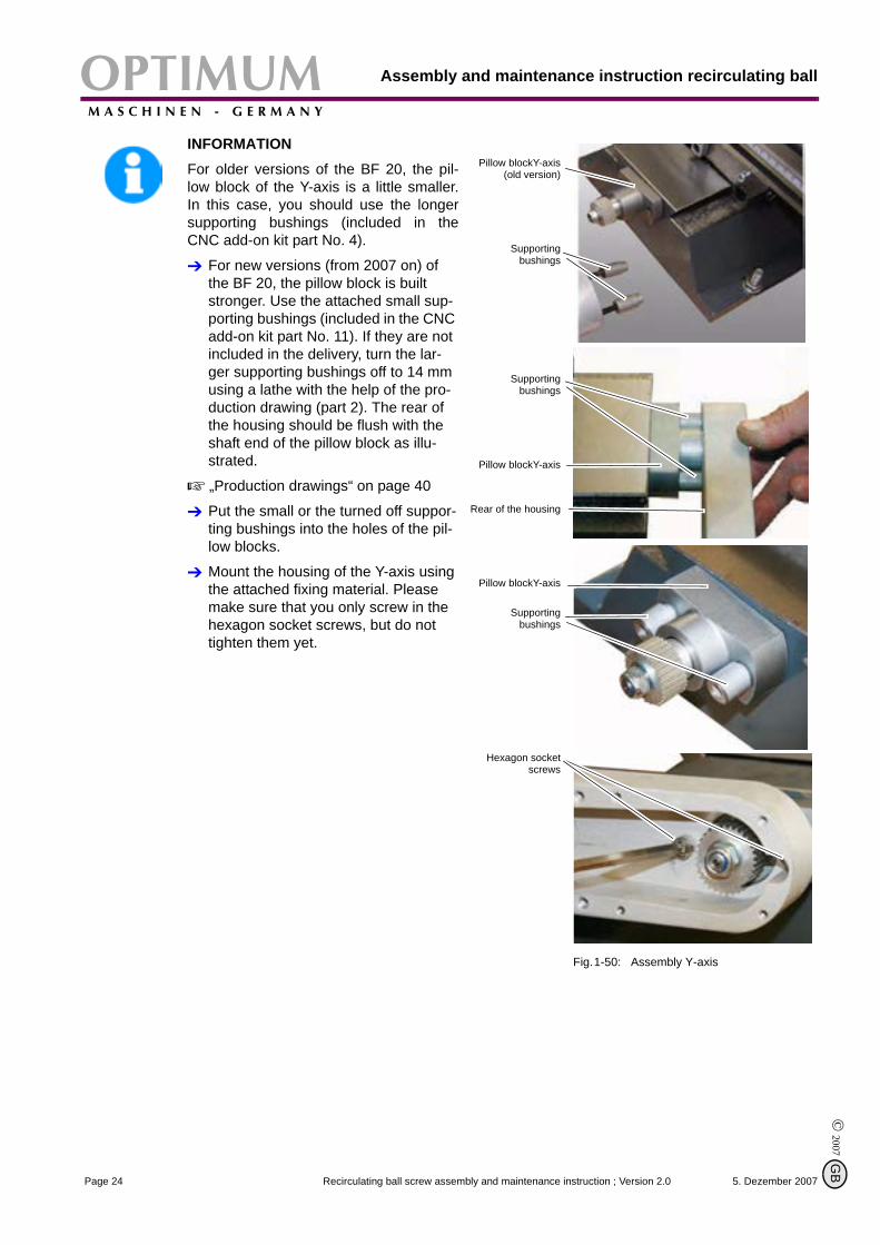
INFORMATIONFor older versions of the BF 20, the pil-low block of the Y-axis is a little smaller.In this case, you should use the longersupporting bushings (included in theCNC add-on kit part No. 4).
For new versions (from 2007 on) of the BF 20, the pillow block is built stronger. Use the attached small sup-porting bushings (included in the CNC add-on kit part No. 11). If they are not included in the delivery, turn the lar-ger supporting bushings off to 14 mm using a lathe with the help of the pro-duction drawing (part 2). The rear of the housing should be flush with the shaft end of the pillow block as illu-strated.
„Production drawings“ on page 40
Put the small or the turned off suppor-ting bushings into the holes of the pil-low blocks.
Mount the housing of the Y-axis using the attached fixing material. Please make sure that you only screw in the hexagon socket screws, but do not tighten them yet.
Fig.1-50: Assembly Y-axis
Pillow blockY-axis(old version)
Supportingbushings
Supportingbushings
Pillow blockY-axis
Rear of the housing
Pillow blockY-axis
Supportingbushings
Hexagon socketscrews
5. Dezember 2007Page 24 Recirculating ball screw assembly and maintenance instruction ; Version 2.0
B

OPTIMUMM A S C H I N E N - G E R M A N Y
Assembly and maintenance instruction recirculating ball screw
© 2
007
GB
Put the support of the Y-axis on the spindle nut.
Fix the support to the spindle nut using the hexagon socket screws. Apply a securing mean before screwing the hexagon socket screws.
Clamp the fixture. Before clamping the fixture, turn the cross table once completely to the front and to the back. Clamp the support to the front position of the cross table.
When mounting the CNC kit you should no longer use the clamping lever to clamp the table since they might possibly interfere when traveling the axis. Use hexagon sok-ket screws with counternuts instead.
Now fasten the hexagon socket screws on the housing.
Now mount the remaining parts of the CNC add-on kit (CNC conver-sion instructions).
Fig.1-51: Assembly Y-axis
Support Y-axis
Spindle nut
Support Y-axis
Securing mean
Hexagon socketscrews
Support Y-axis
Hexagon socketscrews
Housing
Hexagon socketscrews
5. Dezember 2007 Page 25Recirculating ball screw assembly and maintenance instruction ; Version 2.0
Assembly and maintenance instruction recirculating ballOPTIMUMM A S C H I N E N - G E R M A N Y
© 2007
G
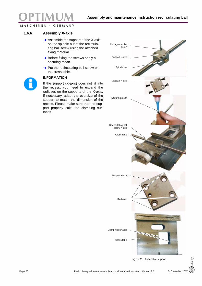
1.6.6 Assembly X-axis
Assemble the support of the X-axis on the spindle nut of the recircula-ting ball screw using the attached fixing material.
Before fixing the screws apply a securing mean.
Put the recirculating ball screw on the cross table.
INFORMATIONIf the support (X-axis) does not fit intothe recess, you need to expand theradiuses on the supports of the X-axis.If necessary, adapt the oversize of thesupport to match the dimension of therecess. Please make sure that the sup-port properly suits the clamping sur-faces.
Fig.1-52: Assemble support
Hexagon socketscrew
Support X-axis
Spindle nut
Support X-axis
Securing mean
Recirculating ballscrew X-axis
Cross table
Support X-axis
Radiuses
Clamping surfaces
Cross table
5. Dezember 2007Page 26 Recirculating ball screw assembly and maintenance instruction ; Version 2.0
B
OPTIMUMM A S C H I N E N - G E R M A N Y
Assembly and maintenance instruction recirculating ball screw
© 2
007
GB
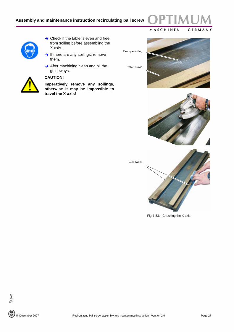
Check if the table is even and free from soiling before assembling the X-axis.
If there are any soilings, remove them.
After machining clean and oil the guideways.
CAUTION!Imperatively remove any soilings,otherwise it may be impossible totravel the X-axis!
Fig.1-53: Checking the X-axis
Example soiling
Table X-axis
Guideways
5. Dezember 2007 Page 27Recirculating ball screw assembly and maintenance instruction ; Version 2.0
Assembly and maintenance instruction recirculating ballOPTIMUMM A S C H I N E N - G E R M A N Y
© 2007
G
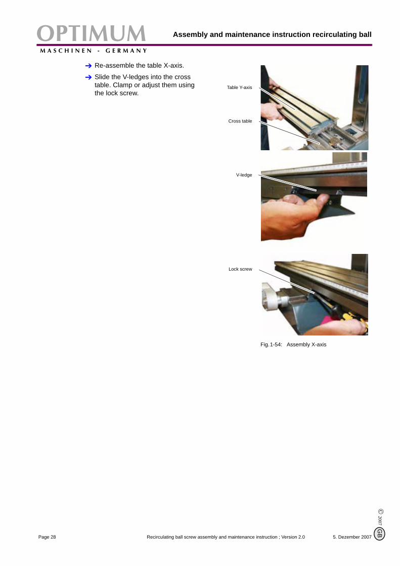
Re-assemble the table X-axis.
Slide the V-ledges into the cross table. Clamp or adjust them using the lock screw.
Fig.1-54: Assembly X-axis
Table Y-axis
Cross table
V-ledge
Lock screw
5. Dezember 2007Page 28 Recirculating ball screw assembly and maintenance instruction ; Version 2.0
B
OPTIMUMM A S C H I N E N - G E R M A N Y
Assembly and maintenance instruction recirculating ball screw
© 2
007
GB
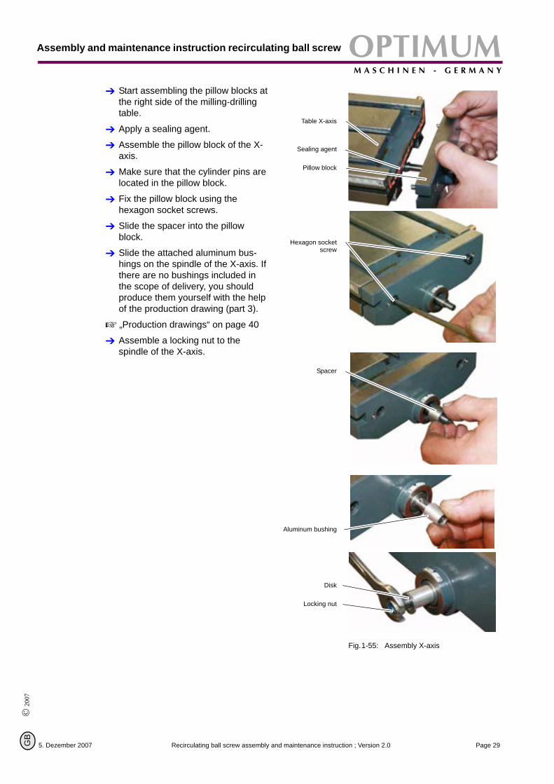
Start assembling the pillow blocks at the right side of the milling-drilling table.
Apply a sealing agent.
Assemble the pillow block of the X-axis.
Make sure that the cylinder pins are located in the pillow block.
Fix the pillow block using the hexagon socket screws.
Slide the spacer into the pillow block.
Slide the attached aluminum bus-hings on the spindle of the X-axis. If there are no bushings included in the scope of delivery, you should produce them yourself with the help of the production drawing (part 3).
„Production drawings“ on page 40
Assemble a locking nut to the spindle of the X-axis.
Fig.1-55: Assembly X-axis
Table X-axis
Sealing agent
Pillow block
Hexagon socketscrew
Spacer
Aluminum bushing
Disk
Locking nut
5. Dezember 2007 Page 29Recirculating ball screw assembly and maintenance instruction ; Version 2.0
Assembly and maintenance instruction recirculating ballOPTIMUMM A S C H I N E N - G E R M A N Y
© 2007
G
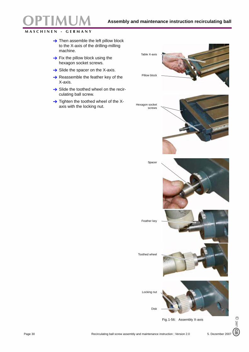
Then assemble the left pillow block to the X-axis of the drilling-milling machine.
Fix the pillow block using the hexagon socket screws.
Slide the spacer on the X-axis.
Reassemble the feather key of the X-axis.
Slide the toothed wheel on the recir-culating ball screw.
Tighten the toothed wheel of the X-axis with the locking nut.
Fig.1-56: Assembly X-axis
Table X-axis
Pillow block
Hexagon socketscrews
Spacer
Feather key
Toothed wheel
Locking nut
Disk
5. Dezember 2007Page 30 Recirculating ball screw assembly and maintenance instruction ; Version 2.0
B
OPTIMUMM A S C H I N E N - G E R M A N Y
Assembly and maintenance instruction recirculating ball screw
© 2
007
GB
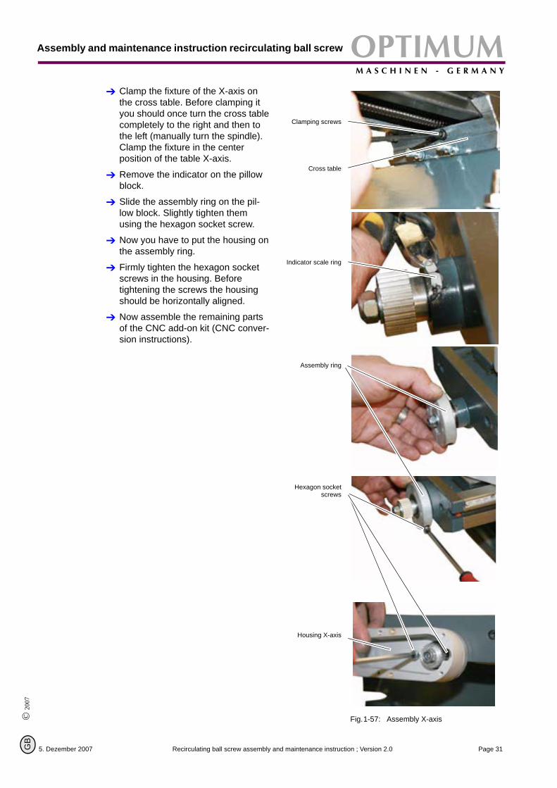
Clamp the fixture of the X-axis on the cross table. Before clamping it you should once turn the cross table completely to the right and then to the left (manually turn the spindle). Clamp the fixture in the center position of the table X-axis.
Remove the indicator on the pillow block.
Slide the assembly ring on the pil-low block. Slightly tighten them using the hexagon socket screw.
Now you have to put the housing on the assembly ring.
Firmly tighten the hexagon socket screws in the housing. Before tightening the screws the housing should be horizontally aligned.
Now assemble the remaining parts of the CNC add-on kit (CNC conver-sion instructions).
Fig.1-57: Assembly X-axis
Clamping screws
Cross table
Indicator scale ring
Assembly ring
Hexagon socketscrews
Housing X-axis
5. Dezember 2007 Page 31Recirculating ball screw assembly and maintenance instruction ; Version 2.0
Assembly and maintenance instruction recirculating ballOPTIMUMM A S C H I N E N - G E R M A N Y
© 2007
G
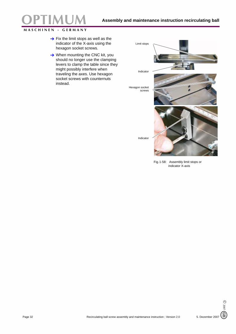
Fix the limit stops as well as the indicator of the X-axis using the hexagon socket screws.
When mounting the CNC kit, you should no longer use the clamping levers to clamp the table since they might possibly interfere when traveling the axes. Use hexagon socket screws with counternuts instead.
Fig.1-58: Assembly limit stops or indicator X-axis
Limit stops
Indicator
Hexagon socketscrews
Indicator
5. Dezember 2007Page 32 Recirculating ball screw assembly and maintenance instruction ; Version 2.0
B
OPTIMUMM A S C H I N E N - G E R M A N Y
Assembly and maintenance instruction recirculating ball screw
© 2
007
GB
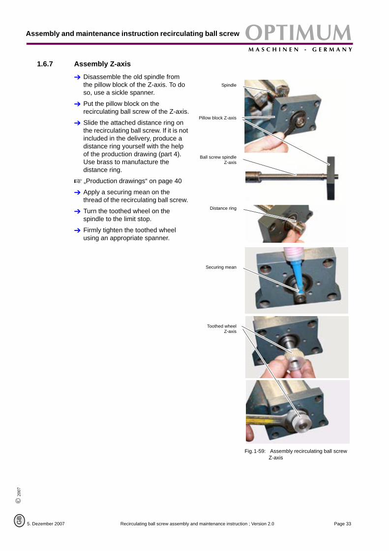
1.6.7 Assembly Z-axis
Disassemble the old spindle from the pillow block of the Z-axis. To do so, use a sickle spanner.
Put the pillow block on the recirculating ball screw of the Z-axis.
Slide the attached distance ring on the recirculating ball screw. If it is not included in the delivery, produce a distance ring yourself with the help of the production drawing (part 4). Use brass to manufacture the distance ring.
„Production drawings“ on page 40
Apply a securing mean on the thread of the recirculating ball screw.
Turn the toothed wheel on the spindle to the limit stop.
Firmly tighten the toothed wheel using an appropriate spanner.
Fig.1-59: Assembly recirculating ball screw Z-axis
Spindle
Pillow block Z-axis
Ball screw spindleZ-axis
Distance ring
Securing mean
Toothed wheelZ-axis
5. Dezember 2007 Page 33Recirculating ball screw assembly and maintenance instruction ; Version 2.0
Assembly and maintenance instruction recirculating ballOPTIMUMM A S C H I N E N - G E R M A N Y
© 2007
G
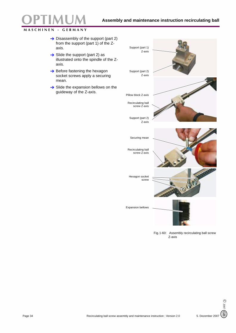
Disassembly of the support (part 2) from the support (part 1) of the Z-axis.
Slide the support (part 2) as illustrated onto the spindle of the Z-axis.
Before fastening the hexagon socket screws apply a securing mean.
Slide the expansion bellows on the guideway of the Z-axis.
Fig.1-60: Assembly recirculating ball screw Z-axis
Support (part 1) Z-axis
Support (part 2) Z-axis
Pillow block Z-axis
Recirculating ballscrew Z-axis
Support (part 2) Z-axis
Securing mean
Recirculating ballscrew Z-axis
Hexagon socketscrew
Expansion bellows
5. Dezember 2007Page 34 Recirculating ball screw assembly and maintenance instruction ; Version 2.0
B
OPTIMUMM A S C H I N E N - G E R M A N Y
Assembly and maintenance instruction recirculating ball screw
© 2
007
GB
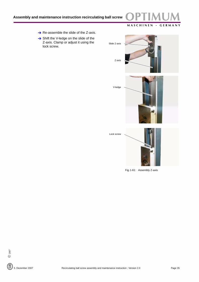
Re-assemble the slide of the Z-axis.
Shift the V-ledge on the slide of the Z-axis. Clamp or adjust it using the lock screw.
Fig.1-61: Assembly Z-axis
Slide Z-axis
Z-axis
V-ledge
Lock screw
5. Dezember 2007 Page 35Recirculating ball screw assembly and maintenance instruction ; Version 2.0
Assembly and maintenance instruction recirculating ballOPTIMUMM A S C H I N E N - G E R M A N Y
© 2007
G
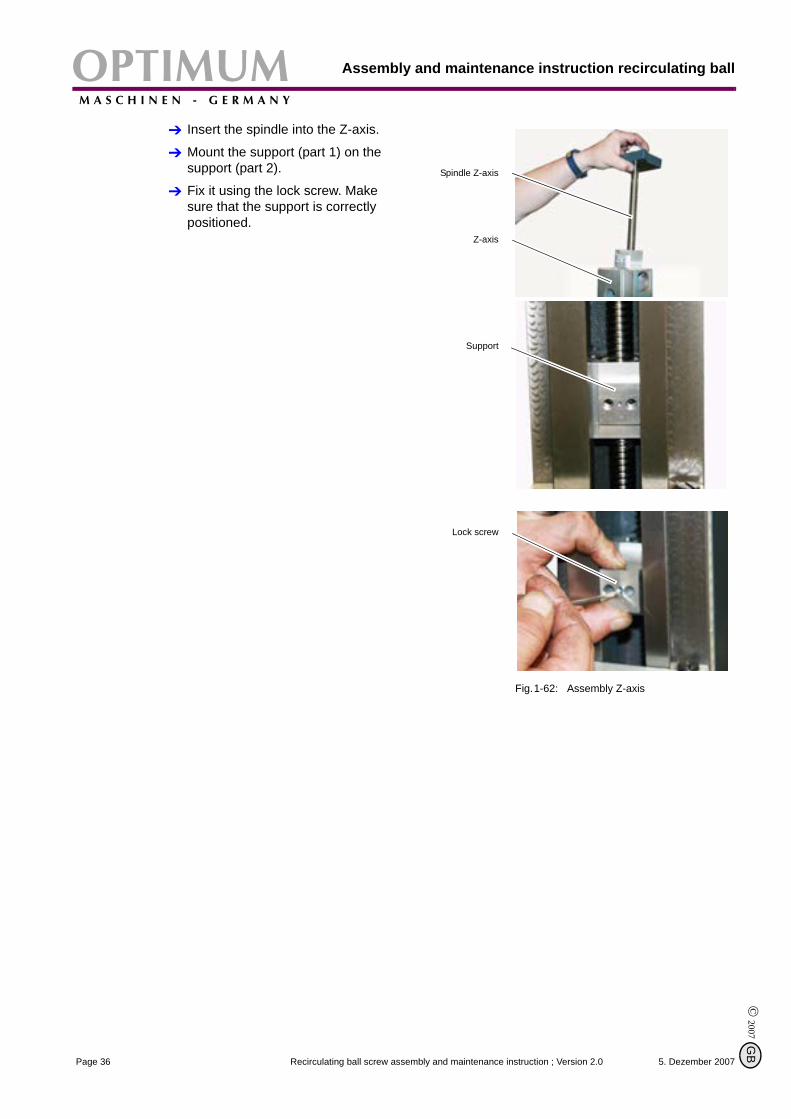
Insert the spindle into the Z-axis.
Mount the support (part 1) on the support (part 2).
Fix it using the lock screw. Make sure that the support is correctly positioned.
Fig.1-62: Assembly Z-axis
Spindle Z-axis
Z-axis
Support
Lock screw
5. Dezember 2007Page 36 Recirculating ball screw assembly and maintenance instruction ; Version 2.0
B
OPTIMUMM A S C H I N E N - G E R M A N Y
Assembly and maintenance instruction recirculating ball screw
© 2
007
GB
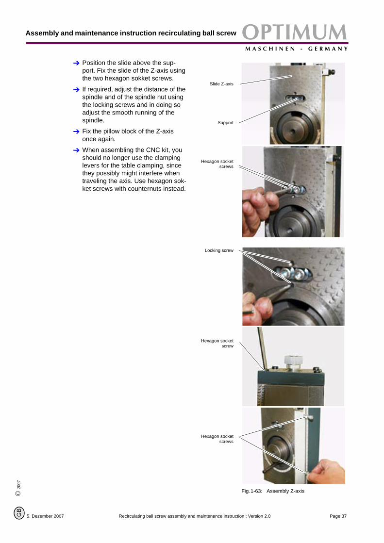
Position the slide above the sup-port. Fix the slide of the Z-axis using the two hexagon sokket screws.
If required, adjust the distance of the spindle and of the spindle nut using the locking screws and in doing so adjust the smooth running of the spindle.
Fix the pillow block of the Z-axis once again.
When assembling the CNC kit, you should no longer use the clamping levers for the table clamping, since they possibly might interfere when traveling the axis. Use hexagon sok-ket screws with counternuts instead.
Fig.1-63: Assembly Z-axis
Slide Z-axis
Support
Hexagon socketscrews
Locking screw
Hexagon socketscrew
Hexagon socketscrews
5. Dezember 2007 Page 37Recirculating ball screw assembly and maintenance instruction ; Version 2.0
Assembly and maintenance instruction recirculating ballOPTIMUMM A S C H I N E N - G E R M A N Y
© 2007
G
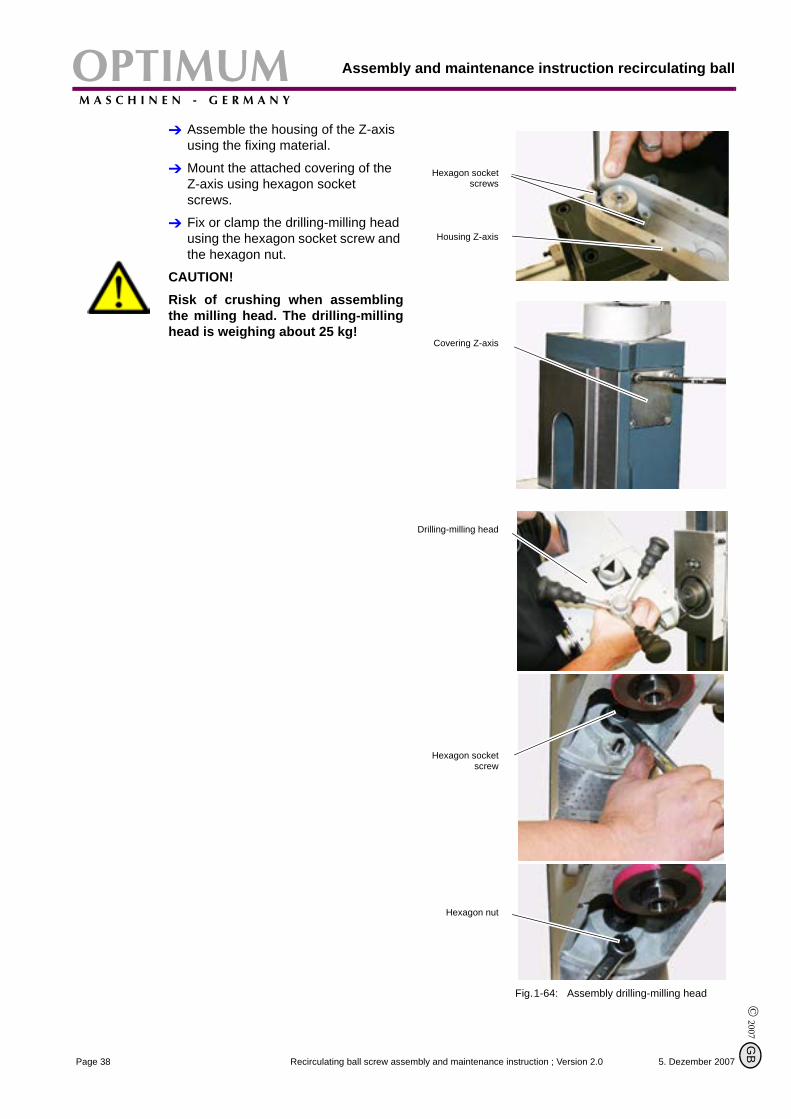
Assemble the housing of the Z-axis using the fixing material.
Mount the attached covering of the Z-axis using hexagon socket screws.
Fix or clamp the drilling-milling head using the hexagon socket screw and the hexagon nut.
CAUTION!Risk of crushing when assemblingthe milling head. The drilling-millinghead is weighing about 25 kg!
Fig.1-64: Assembly drilling-milling head
Hexagon socketscrews
Housing Z-axis
Covering Z-axis
Drilling-milling head
Hexagon socketscrew
Hexagon nut
5. Dezember 2007Page 38 Recirculating ball screw assembly and maintenance instruction ; Version 2.0
B
OPTIMUMM A S C H I N E N - G E R M A N Y
Assembly and maintenance instruction recirculating ball screw
© 2
007
GB
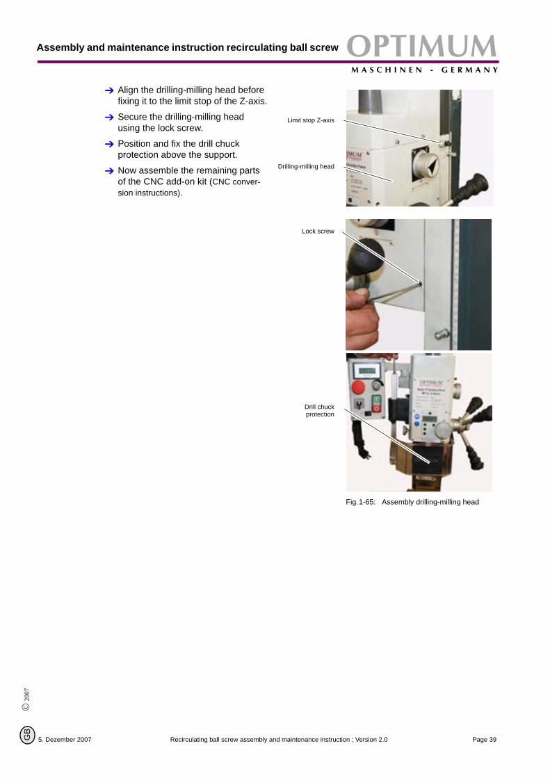
Align the drilling-milling head before fixing it to the limit stop of the Z-axis.
Secure the drilling-milling head using the lock screw.
Position and fix the drill chuck protection above the support.
Now assemble the remaining parts of the CNC add-on kit (CNC conver-sion instructions).
Fig.1-65: Assembly drilling-milling head
Limit stop Z-axis
Drilling-milling head
Lock screw
Drill chuckprotection
5. Dezember 2007 Page 39Recirculating ball screw assembly and maintenance instruction ; Version 2.0
Assembly and maintenance instruction recirculating ballOPTIMUMM A S C H I N E N - G E R M A N Y
© 2007
G
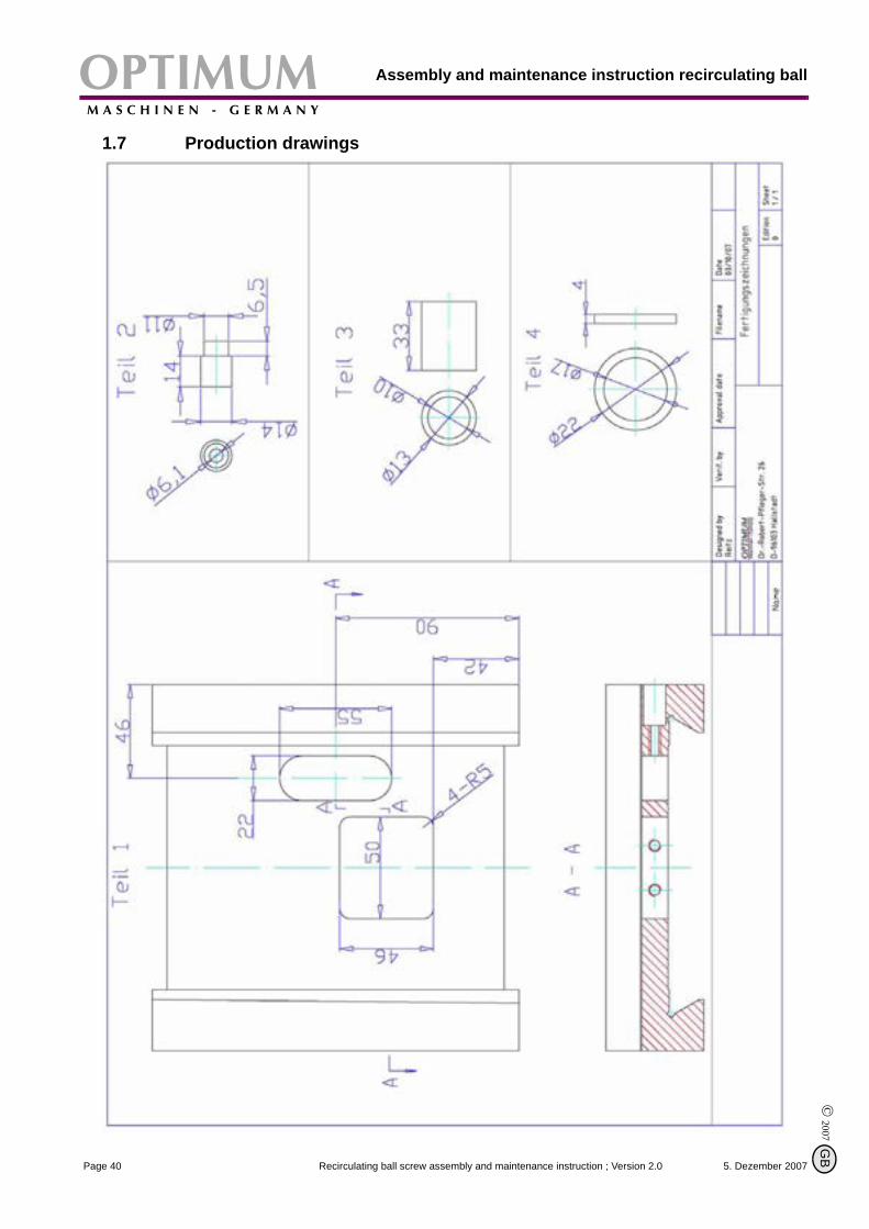
1.7 Production drawings
5. Dezember 2007Page 40 Recirculating ball screw assembly and maintenance instruction ; Version 2.0
B
OPTIMUMM A S C H I N E N - G E R M A N Y
Appendix
© 2
007
GB
2 Appendix
2.1 Copyright© 2007
The documentation is copyright. All derived rights are also reserved, especially those of transla-tion, re-printing, use of figures, broadcast, reproduction by photo-mechanical or similar meansand recording in data processing systems, neither partial nor total.
The company reserves the right to make technical alternations without prior notice.
2.2 WarrantyWithin the term of warranty, the company Optimum warrants for a perfect quality of its productsand will reimburse any cost for overhaul or exchange of defective parts in case of constructionerror, fault in material and/or defect of fabrication.
The term of warranty for commercial use is 12 months and for the use as an amateur it is 24months. Condition for a warranty claim due to construction errors, faults in material and/ordefects of fabrication is:
Proof of purchase and that the instructions for use had been followed.In order to assert the claim of warranty, you have to present a typescript original receipt of purchase. It must comprise the complete address, date of purchase and type designation of the product.The instruction for use of the corresponding device as well as the safety information are to be observed. Damage due to operator’s mistakes may not be accepted as warranty claims.Correct use of the devices.The products of the company Optimum had been designed and built for certain purposes They are listed in the operating manual.The warranty claim may not be accepted if the operating manual is not being followed pro-perly or if it is used for a purpose which has not been intended or with improper accessory.Maintenance work and cleaning.It is absolutely necessary to maintain and clean the machine in regular intervals according to the prescriptions of the instruction for use.By intervention of a third party, any warranty claim will expire. Maintenance work and cleaning are usually not part of the claim of warranty.Original spare partsMake sure to use only original spare parts and original accessory. This can be acquired from authorized distributors of the machine. When other than original parts are being used, conse-quential damages may occur and danger of accidents will increase. Disassembled or partially disassembled devices and devices which are repaired with foreign parts are excluded from warranty claims.Wearing partsCertain components are subject to wear out by time respectively a standard wear by use on the corresponding machine.Among these components are e.g. V-belts, ball bearings, switches, main cables, gaskets and washers, etc. These wearing parts are not part of the warranty.
5. Dezember 2007 Page 41Recirculating ball screw assembly and maintenance instruction ; Version 2.0
AppendixOPTIMUMM A S C H I N E N - G E R M A N Y
© 2007
G
2.3 Product follow-upWe are required to perform a follow-up service for our products which extends beyond shipment.
We would be grateful if you could send us the following information:
Modified settingsExperiences with the recirculating ball screw, which could be important for other usersRecurring failures.
Optimum Maschinen Germany GmbHDr.-Robert-Pfleger-Str. 26
D-96103 Hallstadt
Fax +49 (0) 951 - 96 822 - 22E-Mail: [email protected]
5. Dezember 2007Page 42 Recirculating ball screw assembly and maintenance instruction ; Version 2.0
B