Embed Size (px)
Citation preview

1 6507921 (9-00)
ACCU-MasterAUTOMATIC
REEL MOWER GRINDER
ASSEMBLYand
SERVICEMANUAL
WARNINGYou must thoroughly read and understand thismanual before assembling or maintaining theequipment, paying particular attention to theWarning & Safety instructions.

2
The Warning Symbol identifies special instructionsor procedures which, if not correctly followed, couldresult in personal injury.
The Caution Symbol identifies special instructionsor procedures which, if not strictly observed, couldresult in damage to or destruction of equipment.
12. DON'T OVERREACH. Keep proper footing andbalance at all times.
13. MAINTAIN GRINDER WITH CARE. Followinstructions in Service Manual for lubrication andpreventive maintenance.
14. DISCONNECT POWER BEFORE SERVICING,or when changing the grinding wheel.
15. REDUCE THE RISK OF UNINTENTIONALSTARTING. Make sure the switch is OFF beforeplugging in the Grinder.
16. USE RECOMMENDED ACCESSORIES. Consultthe manual for recommended accessories. Usingimproper accessories may cause risk of personalinjury.
17. CHECK DAMAGED PARTS. A guard or otherpart that is damaged or will not perform its intendedfunction should be properly repaired or replaced.
18. KNOW YOUR EQUIPMENT. Read this manualcarefully. Learn its application and limitations aswell as specific potential hazards.
19. KEEP ALL SAFETY DECALS CLEAN ANDLEGIBLE. If safety decals become damaged orillegible for any reason, replace immediately. Referto replacement parts illustrations in Service Manualfor the proper location and part numbers of safetydecals.
20. DO NOT OPERATE THE GRINDER WHEN UNDERTHE INFLUENCE OF DRUGS, ALCOHOL, ORMEDICATION.
SAFETY INSTRUCTIONS
1. KEEP GUARDS IN PLACE and in working order.
2. REMOVE WRENCHES AND OTHER TOOLS.
3. KEEP WORK AREA CLEAN.
4. DON'T USE IN DANGEROUS ENVIRONMENT.Don't use Grinder in damp or wet locations, orexpose it to rain. Keep work area well lighted.
5. KEEP ALL VISITORS AWAY. All visitors shouldbe kept a safe distance from work area.
6. MAKE WORK AREA CHILD-PROOF with padlocks or master switches.
7. DON'T FORCE THE GRINDER. It will do thejob better and safer if used as specified in thismanual.
8. USE THE RIGHT TOOL. Don't force the Grinderor an attachment to do a job for which it was notdesigned.
9. WEAR PROPER APPAREL. Wear no looseclothing, gloves, neckties, or jewelry which mayget caught in moving parts. Nonslip footwear isrecommended. Wear protective hair covering tocontain long hair.
10. ALWAYS USE SAFETY GLASSES.
11. SECURE YOUR WORK. Make certain that thecutting unit is securely fastened with the clampsprovided before operating.
Safety Awareness Symbols are inserted into this manualto alert you to possible Safety Hazards. Whenever yousee these symbols, follow their instructions.

3
DO1. DO always HANDLE AND STORE wheels in a
CAREFUL manner.
2. DO VISUALLY INSPECT all wheels beforemounting for possible damage.
3. DO CHECK MACHINE SPEED against theestablished maximum safe operating speedmarked on wheel.
4. DO CHECK MOUNTING FLANGES for equaland correct diameter.
5. DO USE MOUNTING BLOTTERS whensupplied with wheels.
6. DO be sure WORK REST is properly adjusted.
7. DO always USE A SAFETY GUARDCOVERING at least one-half of the grindingwheel.
8. DO allow NEWLY MOUNTED WHEELS to runat operating speed, with guard in place, for atleast one minute before grinding.
9. DO always WEAR SAFETY GLASSES or sometype of eye protection when grinding.
IMPROPER USE OF GRINDING WHEEL MAY CAUSEBREAKAGE AND SERIOUS INJURY.
SAFETY INSTRUCTIONS
Grinding is a safe operation if the few basic rules listed below are followed. Theserules are based on material contained in the ANSI B7.1 Safety Code for "Use, Careand Protection of Abrasive Wheels". For your safety, we suggest you benefit fromthe experience of others and carefully follow these rules.
AVOID INHALATION OF DUST generated by grinding and cutting operations.Exposure to dust may cause respiratory ailments. Use approved NIOSH orMSHA respirators, safety glasses or face shields, and protective clothing.Provide adequate ventilation to eliminate dust, or to maintain dust level belowthe Threshold Limit Value for nuisance dust as classified by OSHA.
DON'T1. DON'T use a cracked wheel or one that HAS
BEEN DROPPED or has become damaged.
2. DON'T FORCE a wheel onto the machine ORALTER the size of the mounting hole - ifwheel won't fit the machine, get one that will.
3. DON'T ever EXCEED MAXIMUMOPERATING SPEED established for thewheel.
4. DON'T use mounting flanges on which thebearing surfaces ARE NOT CLEAN, FLATAND FREE OF BURNS.
5. DON'T TIGHTEN the mounting nutexcessively.
6. DON'T grind on the SIDE OF THE WHEEL(see Safety Code B7.2 for exception).
7. DON'T start the machine until the WHEELGUARD IS IN PLACE.
8. DON'T JAM work into the wheel.
9. DON'T STAND DIRECTLY IN FRONT of agrinding wheel whenever a grinder is started.
10. DON'T FORCE GRINDING so that motorslows noticeably or work gets hot.

4
This machine is intended for grinding the reel of reel type mower units ONLY.Any use other than this may cause personal injury and void the warranty.
To assure the quality and safety of your machine and to maintain thewarranty, you MUST use original equipment manufactures replacementparts and have any repair work done by a qualified professional.
ALL operators of this equipment must be thoroughly trained BEFOREoperating the equipment.
Do not use compressed air to clean grinding dust from the machine. Thisdust can cause personal injury as well as damage to the grinder. Machineis for indoor use only. Do not use a power washer to clean the machine.
CONTENTSSafety Warnings ............................................................................................................. Page 2-4Service Data .................................................................................................................. Page 5Assembly Instructions ..................................................................................................... Page 7-10Maintenance Instructions ................................................................................................ Page 11-14Adjustments ................................................................................................................... Page 16-23Machine Service ............................................................................................................. Page 24-25Electrical Troubleshooting Index . ................................................................................... Page 26Electrical Troubleshooting .............................................................................................. Page 27-58Mechanical Troubleshooting ........................................................................................... Page 60-61Parts Lists ...................................................................................................................... Page 62-95Electrical Diagrams ............................................... Separate Drawings Included in the Product Packet
SPECIFICATIONSElectrical Requirements ............................. 115V 50/60 Hz, 20 amp circuitNet Weight ................................................ 2300 lbs [1045 kg]Shipping Weight ........................................ 2500 lbs [1140 kg]Maximum Grinding Length ......................... 34 in. [86 cm]
The grinder is equipped with a low voltage relay whichis factory preset at 100 VAC. If the power supply linedoes not deliver 100 VAC power under load, the relaywill open and trip out the starter. If this occurs, yourpower supply line is inadequate and must be correctbefore proceeding further with the grinder.
ADJUSTMENT OF THE LOW VOLTAGE RE-LAY MAY CAUSE ELECTRICAL COMPONENTFAILURE. ADJUSTMENT OF THE LOWVOLTAGE RELAY WILL VOID ALLELECTRICAL COMPONENT WARRANTY.
Low Voltage Relay

5
Throughout this manual we refer to torque requirementsas "firmly tighten" or the like. For more specifictorque values, refer to the information below.
Bolts Going Into a Nut, or Into a Thread Hole inSteelRefer to the table at the right.
Bolts Going Into a Thread Hole in AluminumUse the Grade 2 values in the table at the right.
Socket-Head Screws Going Into a Nut or SteelUse the Grade 8 values in the table at the right.
Machine ScrewsNo. 6 screws: 11 in.-lbs (0.125 kg-m)No. 8 screws: 20 in.-lbs (0.23 kg-m)No. 10 screws: 32 in.-lbs (0.37 kg-m)
SKILL AND TRAINING REQUIRED FOR SERVICING
This Service Manual is designed for technicians who have the necessary mechanical andelectrical knowledge and skills to reliably test and repair the ACCU-Master Grinder. For thosewithout that background, service can be arranged through your local distributor.
This Manual presumes that you are already familiar with the normal operation of the Grinder. Ifnot, you should read the Operators Manual, or do the servicing in conjunction with someonewho is familiar with its operation.
Persons without the necessary knowledge and skills should not remove the control box coveror attempt any internal troubleshooting, adjustments, or parts replacement.
If you have questions not answered in this manual, please call your distributor. They willcontact the manufacturer if necessary.
SERVICE DATA
TORQUE REQUIREMENTS GRADE 2 GRADE 5 GRADE 8
SMOOTH 3 MARKS 6 MARKS HEAD on HEAD on HEAD
1/4 In. 6 ft-lbs 9 ft-lbs 13 ft-lbs thread (0.8 kg-m) (1.25 kg-m) (1.8 kg-m)
5/16 In. 11 ft-lbs 18 ft-lbs 28 ft-lbs thread (1.5 kg-m) (2.5 kg-m) (3.9 kg-m)
3/8 In. 19 ft-lbs 31 ft-lbs 46 ft-lbs thread (2.6 kg-m) (4.3 kg-m) (6.4 kg-m)
7/16 In. 30 ft-lbs 50 ft-lbs 75 ft-lbs thread (4.1 kg-m) (6.9 kg-m) (10.4 kg-m)
1/2 In. 45 ft-lbs 75 ft-lbs 115 ft-lbs thread (6.2 kg-m) (10.4 kg-m) (15.9 kg-m)

6
Remove the sides, front, and back of the crate. Removethe plastic bag, shrink wrap and bubble wrap aroundcontrol panel. Remove the metal clips that secure thegrinder to the 4 x 6 wood base. With a fork lift, raise thegrinder from the wood base and set it in its final position.See FIG. 1 and 2.
THE UNIT WEIGHS2300 LBS. [1045 kg]. TO LIFT,USE POWER EQUIPMENT.
The Control Panel has a shipping screw and nut installedin its pivot bracket to limit travel during shipping.Remove and discard this screw and nut.
The winch boom is held in place during shipping with awooden brace. Remove and discard this brace.Remove the shrink wrap that holds the winch trolley tothe beam. Remove shipping straps from traversecarriage. Remove window protective sheets.
POSITION BASE
The ACCU-Master will require an operating area of about150" W x 108" D x 87" H [381 x 274 x 221 cm]. Themower reel will be lifted from the front of the machine.The machine operator will operate the unit from this sameposition. Position the base to allow sufficient operatingroom in front of the machine. See FIG. 1 and 2.
The base should be placed on a relatively level concretefloor, with ample ceiling height to allow for the installationof the unit. Do not place the unit across two concreteslab seams or across a large crack.
FIG. 2
ASSEMBLY INSTRUCTIONS
FIG. 1

7
Remove the carton and remove the contents from the cartononto a workbench. The carton includes:
ASSEMBLY INSTRUCTIONS (Continued)

8
ASSEMBLY INSTRUCTIONS (Continued)LEVEL BASE
Each leveling foot has been factory pre-adjusted so it protrudesfrom the base 2 1/4" [57 mm]. See FIG. 3. Place a level onthe top of the table and check the levelness of the unit fromside to side. Adjust the leveling feet as necessary to bring tolevel. See FIG. 4.
Place a level across the table from front to rear. Adjust theleveling feet on the end of the machine as necessary to level.See FIG. 5.
When both front to back and side to side leveling procedureshave been completed, thread the hex jam nuts up againstthe nut that is welded to the bottom until they lock into place.Be careful not to move the leveling feet during this process.See FIG. 3. Make certain that all four leveling feet are firmlycontacting the floor.
Recheck with level after locking nuts are firmly tightened.
FIG. 3
FIG. 5
FIG. 4
2-1/4" [57 mm]

9
ASSEMBLY INSTRUCTIONS (Continued)
FIG. 7
APPLY POWER
BEFORE YOU APPLY POWER TO THEGRINDER, REFER TO THE "IMPORTANTGROUNDING INSTRUCTIONS" ON PAGE 9.
115 Volt Model Only. Plug the control box power cord into astandard 115V AC 15-amp grounded receptacle. See FIG. 7.
220 Volt Model Only. For 220 Volt Applications order PartNo. 6500951, which includes a prewired 3 KVA 220 V stepdown to 115 V 50-60 Hz transformer should be ordered..
IT IS RECOMMENDED THAT THIS ACCU-MASTER REEL MOWER GRINDER HAS ITSOWN PERMANENT POWER CONNECTIONFROM THE POWER DISTRIBUTION PANEL,WITH NO OTHER MAJOR POWER DRAWEQUIPMENT ON THE SAME LINE.
IT IS REQUIRED THAT THE POWERDELIVERED TO THIS GRINDER IS 115 VAC -15 AMPS. THE TOLERANCE ON THISPOWER REQUIREMENT IS +/- 5%.THEREFORE THE MINIMUM VOLTAGEREQUIREMENT IS 109VAC WITH 15 AMPS.VOLTAGE MUST BE CHECKED WITH ALLEQUIPMENT UNDER LOAD (OPERATING) ONTHE CIRCUIT.
DO NOT OPERATE THIS GRINDER WITHAN EXTENSION CORD.
The grinder is equipped with a low voltage relaywhich is factory preset at 100 VAC. If the powersupply line does not deliver 100 VAC power underload, the relay will open and trip out the starter. Ifthis occurs, your power supply line is inadequateand must be correct before proceeding further withthe grinder.
ADJUSTMENT OF THE LOW VOLTAGERELAY MAY CAUSE ELECTRICALCOMPONENT FAILURE. ADJUSTMENTOF THE LOW VOLTAGE RELAY WILLVOID ALL ELECTRICAL COMPONENTWARRANTY.
PROPER GROUNDING OF THE RECEP-TACLE GROUND IN YOUR BUILDING MUSTBE VERIFIED. IMPROPER GROUNDING INYOUR BUILDING MAY CAUSE THE GRINDERTO MALFUNCTION.
FOR 20 AMP RATED LARGE MACHINESBelow is a list of required wire size in your building.
For 0 to 40 Feet from panel to receptacle = Use 12 Ga. Wire.For 40 to 60 Feet from panel to receptacle = Use 10 Ga. Wire.For 60 to 100 Feet from panel to receptacle = Use 8 Ga. Wire.For 100 to 160 Feet from panel to receptacle = Use 6 Ga. Wire.
For 0 to 12 Meters from panel to receptacle = Use 2.5mm Wire.For 12 to 30 Meters from panel to receptacle = Use 4.0mm Wire.

10
For 220 V 50 or 60Hz applications Product No.6500951 should be ordered.
6500951 includes a 3 KVA 220 Volt Step Downto 115 volt 50/60 Hz transformer which isprewired.
The wiring diagram is shown in FIG. 8.
The power cord has no connector. A connectorwhich is appropriate for your locality and 220 volt,8 amp application should be installed.
ASSEMBLY INSTRUCTIONS (Continued)
FIG. 8
IMPORTANT GROUNDING INSTRUCTIONS
In case of a malfunction of breakdown, grounding reduces the risk of electrical shock by providing a pathof least resistance for electrical current.
This Grinder has an electrical cord with an equipment grounding conductor and a grounding plug. Theplug must be plugged into a matching outlet that is properly installed and grounded according to all localor other appropriate electrical codes and ordinances.
Before plugging in the Grinder, make sure it will be connected to a supply circuit protected by a properly-sized circuit breaker or fuse.
Never modify the plug provided with the machine--if it won't fit the outlet, have a proper outlet and circuitinstalled by a qualified electrician.
ALWAYS PROVIDE A PROPER ELECTRICAL GROUND FORYOUR MACHINE. AN IMPROPER CONNECTION CAN CAUSE ADANGEROUS ELECTRICAL SHOCK. IF YOU ARE UNSURE OFTHE PROPER ELECTRICAL GROUNDING PROCEDURE,CONTACT A QUALIFIED ELECTRICIAN.
Use only a qualified electrician tocomplete the installation.

11
PERIODIC MAINTENANCE
FIG. 8
DAILY MAINTENANCE IS SPECIFIED ONPAGE 4 OF THE OPERATOR'S MANUAL, ANDIS TO BE PERFORMED BY THE OPERATOR.LISTED BELOW ARE PERIODIC MAINTENANCEITEMS TO BE PERFORMED BY YOURCOMPANY'S MAINTENANCE DEPARTMENT:
1. Clean the internal bag and cloth filter in thevacuum system weekly or more often dependingon the number of reels ground.
2. Use the grease fitting provided to grease thedovetail with high quality lithium grease monthly.Wipe off excess grease. See FIG. 8.
3. Wipe and re-oil with spray lubricant, the grindingwheel diameter adjusting lead screw every threemonths. Wipe off all excess lubricant. See FIG. 8.
4. Check the gib adjustment on the grinding wheeldiameter adjustment every 3 months. SeeFIG.8.
5. Inspect the Poly-V belt for cracking and adjustthe belt tension per procedure called out in theadjustment section every three months.
6. Wipe and relub with never-seez, the vertical andhorizontal alignment shafts and lead screws,every six months. See FIG. 9.
7. Lift the bellows and wipe off the traversedriveshaft and the bearing rails monthly. Whena squeaking noise is coming from the actuatorbearings, follow the lubrication procedure foractuator and linear bearings. Generally, this willbe every six months to a year.
INSTALL THE FLASHER LIGHT
Locate flasher assembly in carton. Remove thesocket and bulb from the lens. Install lens to the topof the right canopy door using the (2) screws pro-vided with the lens. Attach the ground wire to one ofthe screws. Clip socket and bulb assembly intolens. See FIG. 7.
CONNECTOR TABS ON SOCKETARE VERY FRAGILE AND CARESHOULD BE TAKEN IN ATTACHINGWIRES.
FIG. 9
LEADSCREW (2X)
ALIGNMENTSHAFT (2X)

12
LUBRICATION OF ACTUATOR AND LINEARBEARINGS
STEP 1--Thoroughly clean all three shafts.See FIG. 10.STEP 2--Flood spray all three shafts with a spraylubricant (do not use a teflon based lubricant) until thelubricant is dripping off the shafts. Then run thecarriage back and forth through its range of travel.This will carry the lubricant into the actuator andbearings.NOTE: Because of the flood of lubricant you mayfind that the actuator slips and traversing is erratic orstalls. This is not a problem as it will be corrected inthe subsequent steps.STEP 3--With a clean rag, wipe off the excessamount of lubricant from the shafts. Run the carriageback and forth through its range of travel and wipethe shafts after each traverse. Repeat until the shaftsare dry to the feel. This completes thelubrication process.
If the unit will be shut down for an extended period oftime, more than four weeks, then the shafts and otherappropriate parts of the unit should be flooded withlubricant and that lubricant left in place until the unit isbrought back into service. When the unit is broughtback into service the full lubrication procedure asstated above should be repeated.
FIG. 10
LUBRICATION

13
MAINTENANCE (Continued)CLEANING AND MAINTENANCE GUIDELINES FOR POLYCARBONATE
WINDOWS
Cleaning Instructions
DO NOT USE GASOLINEAdherence to regular and propercleaning procedures is recommendedto preserve appearance and performance.
Washing to Minimize ScratchingWash polycarbonate windows with a mild dish washing liquid detergent and lukewarm water, using aclean soft sponge or a soft cloth. Rinse well with clean water. Dry thoroughly with a moist cellulosesponge to prevent water spots. Do not scrub or use brushes on these windows. Also, do not use butylcellosolve in direct sunlight.Fresh paint splashes and grease can be removed easily before drying by rubbing lightly with a goodgrade of VM&P naphtha or isopropyl alcohol. Afterward, a warm final wash should be made, using amild dish washing liquid detergent solution and ending with a thorough rinsing with clean water.
Minimizing Hairline ScratchesScratches and minor abrasions can be minimized by using a mild automobile polish. Three suchproducts that tend to polish and fill scratches are Johnson paste Wax, Novus Plastic Polish #1 and #2,and Mirror Glaze plastic polish (M.G. M10). It is suggested that a test be made on a corner of thepolycarbonate window with the product selected following the polish manufacturer's instructions.
Some Important "DON'TS"♦ DO NOT use abrasive or highly alkaline cleaners on the polycarbonate windows.♦ Never scrape polycarbonate windows with squeegees, razor blades or other sharp
instruments.♦ Benzene, gasoline, acetone or carbon tetrachloride should NEVER be used on polycarbonate
windows.♦ DO NOT clean polycarbonate windows in hot sun or at elevated temperatures.
Graffiti Removal• Butyl cellosolve, (for removal of paints, marking pen inks, lipstick, etc.)• The use of masking tape, adhesive tape or lint removal tools works well for lifting off old
weathered paints.• To remove labels, stickers, etc., the use of kerosene, VM&P naphtha or petroleum spirits is
generally effective. When the solvent will not penetrate sticker material, apply heat (hairdryer) to soften the adhesive and promote removal.GASOLINE SHOULD NOT BE USED!

14
Battery Installation and Origin SettingUse only the SR44 button-type silver oxide cell.Install the battery with its positive side facing up.
Error Symptoms and RemediesErrC or display flicker:Occurs when the scale surface is stained. Cleanthe scale surface and coat a thin film of low-viscosity oil to keep out moisture.E in the least significant digit:This occurs when the slider is moved too quickly,but it does not affect the measurement. If it stayson when the slider stops, the scale surface isprobably stained. If this is the case, takeremedies as for ErrC.B indication:Battery voltage is low. Replace the battery as soonas possible.
Refer to Operator's Manual page 12, FIG. 7, for digitalgage button functions.
MAINTENANCE (Continued)
DIGITAL GAGE
15
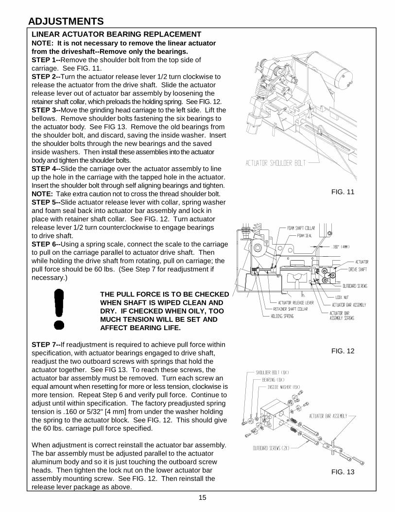
LINEAR ACTUATOR BEARING REPLACEMENTNOTE: It is not necessary to remove the linear actuatorfrom the driveshaft--Remove only the bearings.STEP 1--Remove the shoulder bolt from the top side ofcarriage. See FIG. 11.STEP 2--Turn the actuator release lever 1/2 turn clockwise torelease the actuator from the drive shaft. Slide the actuatorrelease lever out of actuator bar assembly by loosening theretainer shaft collar, which preloads the holding spring. See FIG. 12.STEP 3--Move the grinding head carriage to the left side. Lift thebellows. Remove shoulder bolts fastening the six bearings tothe actuator body. See FIG 13. Remove the old bearings fromthe shoulder bolt, and discard, saving the inside washer. Insertthe shoulder bolts through the new bearings and the savedinside washers. Then install these assemblies into the actuatorbody and tighten the shoulder bolts.STEP 4--Slide the carriage over the actuator assembly to lineup the hole in the carriage with the tapped hole in the actuator.Insert the shoulder bolt through self aligning bearings and tighten.NOTE: Take extra caution not to cross the thread shoulder bolt.STEP 5--Slide actuator release lever with collar, spring washerand foam seal back into actuator bar assembly and lock inplace with retainer shaft collar. See FIG. 12. Turn actuatorrelease lever 1/2 turn counterclockwise to engage bearingsto drive shaft.STEP 6--Using a spring scale, connect the scale to the carriageto pull on the carriage parallel to actuator drive shaft. Thenwhile holding the drive shaft from rotating, pull on carriage; thepull force should be 60 lbs. (See Step 7 for readjustment ifnecessary.)
THE PULL FORCE IS TO BE CHECKEDWHEN SHAFT IS WIPED CLEAN ANDDRY. IF CHECKED WHEN OILY, TOOMUCH TENSION WILL BE SET ANDAFFECT BEARING LIFE.
STEP 7--If readjustment is required to achieve pull force withinspecification, with actuator bearings engaged to drive shaft,readjust the two outboard screws with springs that hold theactuator together. See FIG 13. To reach these screws, theactuator bar assembly must be removed. Turn each screw anequal amount when resetting for more or less tension, clockwise ismore tension. Repeat Step 6 and verify pull force. Continue toadjust until within specification. The factory preadjusted springtension is .160 or 5/32" [4 mm] from under the washer holdingthe spring to the actuator block. See FIG. 12. This should givethe 60 lbs. carriage pull force specified.
When adjustment is correct reinstall the actuator bar assembly.The bar assembly must be adjusted parallel to the actuatoraluminum body and so it is just touching the outboard screwheads. Then tighten the lock nut on the lower actuator barassembly mounting screw. See FIG. 12. Then reinstall therelease lever package as above.
ADJUSTMENTS
FIG. 12
FIG. 11
FIG. 13

16
CARRIAGE LINEAR BEARING REPLACEMENT
STEP 1--Detach the bellows mounting brackets from the carriage.Detach front and rear shields. See FIG. 15.STEP 2--Remove the three screws of one linear bearing and slidethe linear bearing off the end of the carriage shaft.STEP 3--Insert a new linear bearing onto the end of the carriageshaft with the tension adjustment screw pointing outward. SeeFIG. 14. Adjust the tension screw of the linear bearing so whenyou radially rotate the linear bearing around the carriage shaftthere should be no free play between the linear bearing and thecarriage shaft.NOTE: Tension is too tight if you feel a cogging action when yourotate linear bearing around the shaft. This cogging is from theskidding of the bearing on the shaft and indicates tension screw istoo tight.
Finally, sliding the bearing block back and forth should be asmooth uniform motion.
SETTING THE BEARING TENSION CORRECTLYIS CRITICAL TO PROPER GRINDING.BEARINGS WHICH ARE TOO TIGHT OR TOOLOOSE WILL CAUSE POOR GRIND QUALITY.ALSO, BEARINGS WHICH ARE TOO TIGHTWILL HAVE SUBSTANTIALLY SHORTER LIVESAND MAY DAMAGE THE SHAFT.
STEP 4--Slide linear bearing under carriage and attach with thethree screws.NOTE: Repeat Steps 2 thru 4 with the other three linear bearings.STEP 5--After all four linear bearings are reattached to the carriagecheck for correct bearing tension. The bearing tension is correctwhen you try to lift the carriage and can feel no carriage movement,which is free play up and down. The most dependable method ofchecking free play is to use a magnetic base dial indicator attached tothe traverse frame weldment and reading the vertical movementabove each bearing. This movement should be within .001" [.03 mm]Also, when pulling the carriage in the traversing direction, thereshould be only approximately a 3 lb force, with the actuatordisengaged, using a scale system similar to Step 6 of LinearActuator Bearing Replacement Section in this manual. To doublecheck the assembly, slide the carriage assembly from "end oftravel" to "end of travel", it should have very uniform resistancethrough the full range of travel.STEP 6--Replace the bellows carriage mounting brackets onto thecarriage. Replace front and rear shields. See FIG. 15.
ADJUSTMENTS (Continued)
FIG. 14
FIG. 15

17
ADJUSTMENTS (Continued)REEL FINGER DOVETAIL GIB ANDADJUSTING KNOB ADJUSTMENTS
The reel finger slide to the reel finger positioner has a dovetailwith an adjustable gib for tensioning. Tighten the gib setscrews on the side so there is no free play in the dovetailslide. Check for movement when pushing on the relief fingerside to side with a 20 lbs. (44 kg) force. Make sure theknob assembly for adjusting the relief finger to the grindingwheel is rotatable by hand. The gib adjustment should besufficient to maintain a rigid position of the reel finger. SeeFIG. 16.
Check the knob assembly rotating tension by checking thetightness of the nylon plug to the knob assembly threads.The tightness has to be sufficient so the knob assemblydoes not rotate during the relief grinding cycle. See FIG. 17.NOTE: To adjust the nylon plug you must lock the indexfinger assembly down and then adjust the reel fingerpositioner so the clearance holes line up with the nylonplug set screw.
Take up any free play between the tee knob assembly, reelfinger slide and .375 threaded split shaft collar. Loosen theshaft collar locking cap screw and rotate the shaft collaruntil there is no end play. Retighten locking cap screw onthe threaded split shaft collar. See FIG. 16.
GRINDING HEAD BELT TENSION ADJUSTMENT
The grip grinding wheel knob need not be removed for belttensioning adjustment. Remove the six socket head capscrews holding the vacuum hose bracket, the two doubletube clamps and the belt cover. For grinding motor beltadjustment, loosen the four socket head cap screws thatattach the motor. Adjust the grinding motor for proper belttension and tighten the four socket head cap screws.The proper belt tension for the grinding head is to pushdown on the poly V belt half way between to two pulleyswith 5 lbs. [2 kg] of force and belt movement dimensions tobe .12 inches [3 mm]. See FIG. 18.To verify belt tension mount the belt guard with two screws.Turn the motor on. If the belt is tensioned correctly, start-uptorque of the motor through the pulley to the belt shouldhave zero slippage. If there is belt slippage whenturning on the motor there will be a slightsqueal before the belt comes up tospeed. When you achieve correcttension, reassemble all of theremaining parts that have beenremoved.
FIG. 16
FIG. 17
FIG. 18
.12 [3 mm]

18
ADJUSTMENTS (Continued)
FIG. 19
FIG. 21
INDEX FINGER PROXIMITY SETTING
Set all motor switches to the off position.
Put the grind selector switch in the jog cycle.
Press the machine system start switch, so the grinder isoperational.
Push down on the index finger until the stop pin is within.06 inches (1.5 mm) of bottoming out. (You can use a1/16" gage pin or rod stock between the stop pin andindex finger). Set the proximity switch to activate the lightat this setting. This assures the index finger to be closeto its final stop position so the reel is completely indexedbefore the carriage starts to traverse. See FIG. 19.
The spring load force pushing up on the index fingerbrings it away from the proximity when released.
STEPPPER INFEED TRAVEL LIMITS
The infeed stepper maximum extension is 6.0" (152mm) abd minimum compression is 3.5" (89 mm). If youexperience a situation where the grind does not properlyfinish, check that you have not exceeded stepper travelby checking the values per FIG. 20.
LOCKING INDEX FINGER PIN
To align the Index Finger Locking Pin to the hole in theIndex Finger Assembly loosen the two socket head capscrews so the index sensor block is movable. Pushdown on the index finger assembly until the springloaded index finger locks into hole with no binding.Tighten the two socket head cap screws so the indexsensor block is secured, and the locking pin movesfreely. See FIG. 21.
FIG. 20

19
PROXIMITY SWITCHFor the proximity switch to perform properly and reverse thedirection of the carriage at each end of the rails, a distance of3/16" [4 mm] to 1/4" [6 mm] needs to be maintained betweenthe carriage proximity flag bracket and the proximity switch.See FIG. 22.
NOTE: Light on proximity activates when metal crosses overthe switch.
ADJUSTMENTS (Continued)
FIG. 23
Manual/AutoSelector
Manual Reset
Overload Sensor
FREQUENT OVERLOADING AND CIRCUIT TRIPPINGThe magnetic starter is factory set at a 12 AMP rating. See FIG. 23.
If your magnetic starter is frequently shutting down, contact yourdistributor.
The main control power source is for a 20 AMP supply circuit.See machine setup section for explanation.
NOTE: Manual/Auto Selector is factory set at manual mode.
ADJUSTABLE RELIEF TENSIONIf the relief angle appears to vary during relief grinding adjustthe tension on the nylon plug and set screw. See FIG. 22A.
FIG. 22
FIG. 22A

20
SPIN GRINDING ATTACHMENT ADJUSTMENTIf play develops so crank handle wants to rotate in the scissoraction on the spin grinding attachment, the play can beeliminated by tightening the set screw identified in FIG. 24.
If there is too much play in the spin drive pivot points, torquedown the hex nut tight so conical washer is compressed, thenback off 1/2 turn. See FIG. 24.
ADJUSTMENTS (Continued)
TRAVERSE MOTOR COUPLING
Traverse motor shaft must be concentric to traverse drive shaftwithin .010. The traverse shaft and motor shaft are to have atleast 1/8" [3 mm] to 1/2" [13 mm] clearance so they do not contacteach other. The coupling is to be locked down tightly with thespiral grooves equally spaced for the full length. See FIG. 25.
FIG. 25
FIG. 24

21
CONTROL BOARD POTENTIOMETER ADJUSTMENTSTRAVERSE DRIVE CONTROL BOARD (TDC)
The Traverse Drive Control Board has two potentiometers on the board as shown on drawing 6504342 whichis included. Both of the potentiometers are set to the full counterclockwise (CCW) position and should be leftthere. No adjustments are required.
INPUT/OUTPUT CONTROL BOARD (IOC)
The Input/Output Control Board has two potentiometers on the board as shown on drawing 6504342 which isincluded. These potentiometers have been set at the factory to the position shown on the drawing. Also seeFIG. 26.
SPIN DRIVE CONTROL BOARD (SDC)
The Spin Drive Control Board has three potentiometers on the board as shown on drawing 6504342 which isincluded. These potentiometers have been set at the factory to the positions shown on the drawing. Also seeFIG. 27
In the Relief Grinding Mode---The Relief Speed Pot (RSP) and the Relief Torque Pot (RTP) interact with each other. The (RSP) is locatedon the (IOC) Input Output Controller as Pot 1 preset at 9:00 (20 Volts DC). The (RTP) is located on thecontrol panel and is for relief torque adjustment. See FIG. 26.
Relief Speed Pot (RSP) when rotated clockwise will increase maximum spin drive speed. This speed shouldnever be above the 9:30 setting.
Relief Torque Pot (RTP) can vary the reel to finger holding torque for relief grinding. The recommended startingpoint is 30 in/lbs of torque setting. Never adjust the (RTP) potentiometer dial past the red line marking.Setting the reel to finger torque to high could cause the traverse motor system to not operating smoothly.
In the Spin Grinding Mode---the Spin Torque Potentiometer (STP) and the Spin Speed Pot (SSP) interact with each other. The (STP) islocated on the (IOC) Input Output Controller as Pot 2 preset at 1:30 for torque setting. The (SSP) is locatedon the control panel and is for spin speed adjustment. See FIG. 26.
Spin Torque Pot (STP) controls maximum torque allowable in the spin grind cycle only. This should never beadjusted past the 2:30 position. Check the reel spin torque by hand spinning the reel first to check that it is free turning.
The Spin Speed Pot (SSP) controls reel spin speed, adjust as required. This controls the spin drive speed forspinning the reel.
POTENTIOMETERS ON THE SPIN DRIVE CONTROL (SDC) See FIG. 27.
Maximum Speed Pot---The maximum speed is factory preset to 4:30 (fully clockwise) to allow for maximum spin speed.
Minimum Speed Pot---The minimum speed is factory preset at 8:30 (full counterclockwise) so zero speed is obtainable for spinspeed.
IR Compensation Pot---The IR Compensation is factory set at 9:00.
Regulation of the spin or relief grind spin motor may be improved by a slight adjustment of the IR COMP trim potclockwise from its factory-set position. Overcompensation causes the motor to oscillate or to increase speed whenfully loaded. If you reach such a point, turn the IR COMP trim pot counterclockwise until the symptoms justdisappear.

22
GRINDING MOTOR CONTROL BOARD (GMC)
The Grinding Motor Control Board has four potentiometers onthe board as shown on drawing 6504342 which is included.These potentiometers have been set at the factory to thepositions shown on the drawing. See FIG. 28.
Maximum Speed---The maximum speed potentiometer is preset to 1:00 positionfor 90 Volts DC to the grinding motor for 4300 RPM. The 4300RPM is for optimum grinding wheel operating speed. DO NOTgo above the 4300 RPM.Check for 90 Volts DC on Grinding Motor Control (GMC) atTerm A1 to Term A2.
Minimum Speed---The minimum speed is set full counterclockwise so it is non-functional for this application.
Current Limit---The current limit is preset at 3:00 at the factory. The red lightabove the current limit indicates when the grinding motor isabove the preset current limit. This is a visual indicator tocheck while in a grinding cycle. Going above the current limitcauses the motor to pulsate. The current limit can be turnedclockwise to increase the motor's maximum torque for grindingoverloads. The 10 amp circuit breaker on the control panel willtrip if the overload persists for a prolonged period of time. Usea lower grinding head traverse speed if nuisance tripping isexperienced.
IR Compensation---Regulation of the grinder motor may be improved by slightadjustment of the IR COMP trim pot clockwise from its factory-setposition. Overcompensation causes the motor to oscillate or toincrease speed when fully loaded. If you reach such a point,turn the IR COMP trim pot counterclockwise until the symp-toms just disappear.
The control is preset to 9:00 position. Never adjust past the11:00 position when changing the setting toincrease higher torque for heavy grinding.
CONTROL BOARD POTENTIOMETER ADJUSTMENTS (Continued)
FIG. 26
FIG. 28
FIG. 27

23
MACHINE SERVICE
FIG. 29
E-PROM REPLACEMENT
The E-Prom is electrically programmable so replacement is required for a program change. The E-Prom islocated on the (IOC) Input Output Controller on the lower left hand corner at location #U5. See FIG. 29. All E-Proms have software revision level and are dated. NOTE: The "V" notch at one end of the E-Prom is alwaysat the left hand side when mounted on the Input Output Controller Board (IOC).
For replacement of the E-Prom use a special puller or a small .12" [3 mm] wide single blade screw driver. Usea grounding strap or ground yourself with one hand on a machine ground screw. Pry the E-Prom off evenly,going from end to end, between the underside of E-Prom and the top of the base mount.
Take the new E-Prom and make sure each row of pins are in a uniform line and 90 degrees to the top face.The pins are usually less than 90 degrees and to change the angle lay the pins on the rubbermat on thecontrol panel. Rotate so the pins are approximately 90 degrees. Do this to both sides. Make certain toremain grounded during this procedure.
The E-Prom is now ready to insert. Again make certain that the "V" notch at the end of the E-Prom is to theleft side. Place the bottom pins in the lower row first and rotate up into position so the top row of pins areguided in. Press both ends in evenly until seated.
GROUNDING IS CRITICAL IN THIS PROCEDURE. IF A STATIC DISCHARGE OCCURS DURING THEPROCEDURE, THE E-PROM COULD BE DAMAGED.
GROUNDING IS CRITICAL INTHIS PROCEDURE. IF A STATICDISCHARGE OCCURS DURINGTHE PROCEDURE, THE E-PROMCOULD BE DAMAGED.

24
MACHINE SERVICE (Continued)GRINDING HEAD ASSEMBLY
Remove grinding wheel and grinding wheel knob. The Grinding Head Spindle Assembly consists of the grindinghead spindle and a ball bearing press fit together. The other ball bearing is slip fit on the opposite end duringassembly with loctite on the bearing bore. To replace the spindle assembly remove the grinding wheel gripknob, square key and belt cover. See FIG. 30. Loosen the 4 socket head cap screws on the motor to removethe poly-V belt. Loosen the 2 set screws on the spindle pulley and remove the pulley, square key and pulleyspacer. Push on the right hand side of the spindle assembly to compress conical washers so there is no pressureon the shaft retaining ring and to expose the retaining ring for removal. Using a retaining ring pliers remove thesmall retaining ring from the spindle assembly. You can now remove the spindle assembly out the right side bylightly tapping on the left end with a rubber mallet. The second ball bearing can be removed from the belt sideof the Grinding Head Housing.
To reassemble place the 4 conical washers (2 pair nested and then place the 2 pairs back to back) against theball bearing on the new spindle assembly. See FIG. 31. Slide this assembly into the Grinding Head Housingand slip fit the new second ball bearing onto the spindle assembly and into grinding head housing (apply loctite#242 to the bore of the bearing before assembling). Using a C-clamp compress the conical washers so you canreplace the retaining ring. The retaining ring is fragile and easily damaged when removing. Always use a newretaining ring when reassembling the grinding head spindle. Only open the retaining ring enough to install.Opening the ring excessively will damage the retaining ring, making is unusable.
Replace the pulley spacer and mount the square key positioned tight against the pulley spacer. Remount thepulley pushing against the pulley spacer and bottom out against the snap ring with no end play. Next tighten thetwo pulley set screws. Then remount the poly-V belt. (See Grinding Head Belt Tension Adjustment in theadjusting section). Replace belt cover and square key and mount the grinding wheel grip knob and tighten thetwo set screws.
FIG. 30
FIG. 31
THE RETAINING RING IS FRAGILE AND EASILY DAMAGEDWHEN REMOVING. ALWAYS USE A NEW RETAINING RINGWHEN REASSEMBLING THE GRINDING HEAD SPINDLE.ONLY OPEN THERETAINING RING ENOUGH THE INSTALL. OPENING THERING EXCESSIVELY WILL DAMAGE THE RETAINIG RING,MAKING IT UNUSABLE.

25
ELECTRICAL TROUBLESHOOTINGSKILL AND TRAINING REQUIRED FOR ELECTRICAL SERVICING
This Electrical Troubleshooting section is designed for technicians who have the necessary electricalknowledge and skills to reliably test and repair the ACCU-Master electrical system. For those without thatbackground, service can be arranged through your local distributor.
This manual presumes that you are already familiar with the normal operation of the Grinder. If not, youshould read the Operators Manual, or do the servicing in conjunction with someone who is familiar with itsoperation.
Persons without the necessary knowledge and skills should not remove the control box cover or attemptany internal troubleshooting, adjustments, or parts replacement.
If you have any question not answered in this manual, please call your distributor. They will contact themanufacturer if necessary.
WIRE LABELS
All wires on the ACCU-Master have a wire label at each end for troubleshooting. The wire label has acode which tells you wiring information. The wire label has a seven position code. The first two digits arethe wire number: 01-99. The next three numbers or letters are the code for the component to which thewire attaches. Example: IOC for Input/Output Controller. The last two numbers or letters are the numberof the terminal on the component to which the wire attaches.
ELECTRICAL TROUBLESHOOTING INDEX
AC Main Power Controls ................................................................................................. Page 26-27Machine Light ................................................................................................................. Page 28
MANUAL CYCLESpin Drive Controls in Spin Mode .................................................................................... Page 29-31Spin Drive Controls in Relief Mode .................................................................................. Page 32-34Grinding Motor Controls .................................................................................................. Page 35-36Dust Collector Controls .................................................................................................. Page 37-38Winch Controls .............................................................................................................. Page 39
Traverse Drive Controls--w/prox ..................................................................................... Page 40-42Traverse--stopping and reversing .................................................................................... Page 43Stepper Infeed Controls--w/prox ...................................................................................... Page 44-46No Manual (jog) Cycle--no (LCD) Liquid Crystal Display .................................................. Page 47-48No Manual (jog) Cycle--because of system error messages ............................................ Page 49
AUTO CYCLENo Spin Auto Cycle--because of system error messages ................................................ Page 50-51No Relief Auto Cycle--because of system error messages .............................................. Page 52-54No Automatic Cycle ........................................................................................................ Page 55Flashing Light ................................................................................................................. Page 56

26
ELECTRICAL TROUBLESHOOTING (Continued)PROBLEM--AC Main Power Controls: no electrical power to control panel.
In your Product Packet Assembly, there are a series of prints. Find the printtitled AC Power Controls and Junction Box/Light Assembly, before startingthe troubleshooting below. Verify all wires shown on that drawing are correctand pull on wire terminals with approximately 3 lbs force to verify there are noloose terminal connections and/or no loose crimps between wire and terminal.If loose terminals are found, retighten and retest system. If problem persists,test as listed below.
Possible Cause
You must push the SystemStart Switch (SSS) forpower to control Panel
Main Power Cord is notplugged in
Main 20 amp outlet circuitbreaker has tripped
No 115 Volts AC power to(MAG)
No power from junction box
No 115 Volts AC power outof (MAG)
(MAG) not working
Machine worksYes--end troubleshootingNo--go to Step B. next
Machine worksYes--end troubleshootingNo--go to Step C. next
Machine worksYes--end troubleshootingNo--but light works in outlet--go to Step D. nextNo--but light does not work in outlet. You must solve your power delivery problem independent of machine.
(MAG) L1 black wire to L2 white wire115 Volts ACYes--go to Step F. nextNo--go to Step E. next
(WB2) Across main power cord #02white wire to #02 black wire for 115 Volts ACYes--replace panel power cord #05No--replace main power cord #02
(MAG) Term #T1 to T3 for 115 Volts ACYes--go to Step L. nextNo--go to Step G. next
This may have been tripped from either amotor overload condition or duringmachine shipment. Push (SSS). Ifmachine works--Yes--end troubleshootingNo--go to Step H. next
Bad contacts in contactor cause it not tohold in when turned on. If machine worksYes--end troubleshootingNo--go to Step I. next
Checkout Procedure
A. Listen for the Magnetic Starter(MAG) Contacts to pull in with aclunk
B. Plug in main power cord
C. Check circuit breaker and resetif necessary. (Check wall outlet witha light to make sure it works)
D. Check for incoming power (MAG)for 115 Volts AC
E. At rear junction box Wire Block 2(WB2) check for 115 Volts AC
F. Check for 115 Volts ACgoing out
G. Push reset button on top of(MAG)Ref: Factory set for 12 amp
H. Contractor coil chatters when(MAG) is powered up. Tightenterminals T1, T2, & T3 that connectthe overload and contactor together

27
ELECTRICAL TROUBLESHOOTING (Continued)
Checkout Procedure
I. Check at Magnetic Starter coilfor 115 Volts AC with mainelectrical power on and pushing(SSS)
J. Check wire continuity withmachine power off
K. Check wire continuity withmachine power off
L. Check for 115 Volts AC at (WB1)
M. Check wire continuity withmachine power off
N. Check for 115 Volts ACacross normally open contactsof (ESS)
O. Check for 115 Volts AC across(SSS) contacts when machine poweris on and (SSS) has not beenpushed. Check for 0 Volts ACacross (SSS) contacts when pushingon (SSS)
(MAG) Term #A1 to A2 for 115 Volts ACYes--replace magnetic starterNo--go to Step J. next
Verify continuity across (ESS) Term #1 to#2 to be "0" ohms reading. (SSS) Term#3 to (MAG) L1 this check wires #49 and#99. "0" ohms mean wires are goodYes--go to step K. nextNo--replace wires #49 & #99
(MAG) Term A2 to (MAG) L2 this checkswires #53 & 54. "0" ohm reading meanswires are good.Yes--go to Step M. nextNo--replace wires 53, and 54
(WB1) white wire #56 to blackwire #57 for 115 Volts ACYes--end troubleshootingNo--replace wires #56 & #57
(SSS) Term #4 to (MAG) #14 for wires#50 & 52 and separately check (ESS)Term #2 to (MAG) #13 wire #51. "0"ohms means the wire is goodYes--go to Step N. nextNo--replace wires #50, 51 & 52
(ESS) Term #1 to #2 for 115 Volts AC
Yes--go to Step O. nextNo--replace (ESS)
(SSS) Term #3 to #4 for 115 Volts AC(SSS) not pushed. Term #3 to #4 "0"Volts AC (SSS) pushed.Yes--replace (MAG)No--replace (SSS)
Possible Cause
115V power not delivered to(MAG) coil
Bad wires for power to (SSS)
Wire Block 1 (WB1)115 Volts AC verified
Bad wires for power toEmercency Stop Switch (ESS)or (SSS)
(ESS) is bad
(SSS) is bad

28
ELECTRICAL TROUBLESHOOTING (Continued)
Light worksYes--end troubleshootingNo--go to Step B. next
Check for 115 Volts AC across lightcord white wire #03 to switch blackwire #03Yes--go to Step C. nextNo--replace light cord wire #03
Check for 115 Volts AC across ma-chine black wire #10 to white wire #10Yes--replace machine light assembly*No--replace switch assembly
Possible Cause
Light switches arenot turned on or thereis a bad bulb
Wire cord is bad
Switch or machinelight is bad
Checkout Procedure
A. Turn on machine light toggleswitch on lamp holder. Check thelight bulb in another light fixture orreplace with a new bulb. Next turnon light switch electrical junctioncover switch
B. Remove cover of light junctionbox check for 115 Volts AC
C. Check for 115 Volts AC acrossmachine light assembly
PROBLEM--Machine light is not working
Assuming AC main power cord wire #2 has 115 Volts AC at (WB2) Wire Block 2.
In your Product Packet Assembly, there are a series of prints. Find the print titledJunction Box and Light Assembly, before starting the troubleshooting below. Verifyall wires shown on that drawing are correct and pull on wire terminals with approximately3 lbs force to verify there are no loose terminal connections and/or loose crimps betweenwire and terminals. If loose terminals are found, tighten and retest system. If problempersists, test as listed below.
*NOTE: Again we want toremind, that there is aswitch at the back ofthe machine lightassembly, which mustbe turned on for thelight to work.

29
ELECTRICAL TROUBLESHOOTING (Continued)
Possible Cause
Spin Speed Pot (SSP) setto zero
Spin Motor Switch (SMS)or Spin Rotation Switch(SRS) are not on
Circuit Breaker 2 (CB2) istripped (4amp)
Spin Motor Switch (SMS)is not working
Relay 1 (RE1) is notworking
Input Output Control (IOC)is not working
(RE1) contactsare not working
Checkout Procedure
A. Set (SSP) to 200 on the controlpanel.
B. Turn (SMS) switch on.Turn (SRS) switch to directionof reel rotation required.NOTE: center position is off.
C. Reset circuit breaker switch(tripped by current overload)Check that reel is free spinning
D. Check for (SMS) incoming115 Volts AC
E. Check for (SMS) output of115 Volts AC
F. Check for (RE1) input of 0Volts DC at the coil. Reminder,must be in manual (jog) mode.
G. Check output 6 grinding/spinmotor output to (RE1)
H. Check for (RE1) output of115 Volts AC
I. Check for (RE1) input of115 Volts AC
Spin Motor worksYes--end troubleshootingNo--go to Step B. next
Spin Motor worksYes--end troubleshootingNo--go to Step C. next
Spin Motor worksYes--end troubleshootingNo--go to step D. next
(SMS) Term #1 to #2 for 115 Volts ACYes--go to step E. nextNo--go to Step F. next
(SMS) Term #5 to #6 for 115 Volts ACYes--got to Step K. nextNo--replace (SMS) switch
(RE1) Term 0 to term 1 for 0 Volts DCYes--go to Step H. nextNo--If 24 Volts DC go to Step G. next
(IOC) Term 32 to 22 for 0 VDCNo--reads 24 Volts replace (IOC)
(RE1) Term 7 (black wire) to (WB1) WireBlock 1 (white wire) #78 for 115 Volts ACYes--replace wires #98 & #78No--go to step I. next
(RE1) Term 8 (black wire) to (WB1) WireBlock 1 (white wire) #78 for 115 Volts ACYes--replace (RE1)No--go to Step J. next
PROBLEM--Spin Drive not working in (manual) jog mode and in spin mode.
Assuming (SSS) System Start Switch is on and (AMS) Auto/Manual Switch is in (manual) jogwith 115 Volts AC to control panel and all other manual (jog) mode functions are working.
In your Product Packet Assembly, there are a series of prints. Find the print titledSpin Drive Controls before starting the troubleshooting below. Verify all wires shownon that drawing are correct and pull on wire terminals with approximately 3 lbs forceto verify there are no loose terminal connections and/or loose crimps between wire andterminal. If loose terminals are found, tighten and retest system. If problem persists,test as listed below.

30
ELECTRICAL TROUBLESHOOTING (Continued)
Possible Cause
(CB2) is not working (4 amp)
Spin Rotation Switch (SRS)is not working
Spin Drive Control (SDS)is not working.
Spin Drive motor is bad
Spin Speed Pot (SSP)is not working
Input/Output Control (IOC)board is not working
Checkout Procedure
J. Check for (CB2) normallyclosed contacts
K. Check for (SRS) input of115 Volts AC
L. Check for (SRS) output of115 Volts AC NOTE: Check spinrotation switch in both positions.
M. Check (SDC) L1 to L2 for115 Volts AC
N. Check (SDC) A1 & A2 for (SSP)approx 90 Volts DC (Have SpinSpeed Pot set to 400 RPM)
O. Check for approx 90 Volts DCinput to (SRS)
P. Check for approx 90 Volts DCoutput to (SRS)
Q. Check spin motor continuity
R. (SSP) (10K) on control panel
S. Check (IOC) output to the Spin Board.
(WB1) Wire Block 1 (white wire) #78 to(CB2) (black wire) #58 for 115 Volts ACYes--replace (CB2) and wire #70No--replace wire #58
(SRS) Term 5 to term 8 for 115 Volts ACYes-- go to Step L. nextNo--replace wire 77 & 79
(SRS) Term 1 to term 4 for 115 Volts ACYes--go to Step M. nextNo--replace (SRS) switch
(SDC) Term L1 to term L2 for 115 VoltsACYes--go to Step N. nextNo--replace wires 82 & 83
(SDC) Term A1 to A2 for approx 90 Volts DCYes--go to Step O. nextNo--got to Step R. next
(SRS) Term 6 to 7 for approx 90 Volts DCYes--go to Step P. nextNo--replace wires 80 & 81
(SRS) Term 2 to 3 for approx 90 Volts DCYes--go to Step Q. nextNo--replace (SRS) switch
Remove wires at (SRS) Term 2 & 3 check0 ohms across the black and white wiresYes--end troubleshootingNo--go to Step U. next
Input/Output Controller (IOC) Pin #36 to 41Pot Full CCW Pot Full CW0 Volts DC 4.21 Volts DC(IOC) Pin #36 to 43Pot Full CCW Pot Full CW4.21 Volts DC 0 Volts DCYes--go to Step S. nextNo--go to Step U. next
Input/Output Controller (IOC) Pin #33 toPin #41Pot Full CCW Pot Full CW0 Volts DC. 4.21 volts DC(IOC) Pin #33 to Pin #43Pot Full CCW Pot Full CW4.21 volts DC 0 Volts DCYes--Go to Step T.No--Replace (IOC)

31
ELECTRICAL TROUBLESHOOTING (Continued)
(IOC) Pin #40 to 44 .14 Volts DC(IOC) Pin #40 to 46 .06 Volts DCYes--replace (SDC)No--replace (IOC)
Check for 10,000 ohmsRed wire to white wire Full CCW--0 ohms Full CW--10,000 ohmsRed Wire to black wire Full CCW--10,000 ohms Full CW--0 ohmsYes--replace (IOC)No--replace (SSP)
Remove the brushes one at a time andmaintain orientation for reinsertion. Seeif brush is worn short 3/8" [10 mm]minimum length.Yes--replace motor brushes.No--replace Spin Drive Motor
Checkout Procedure
T. (STP) (50K) on (IOC) aspot 2 (preset at 1:30)
U. (SSP) (10K) Remove 3wiresred wire to term #36 (IOC)white wire to term #41 (IOC)black wire to term #43 (IOC)
V. Inspect Motor Brushes
Possible Cause
Spin Torque Pot (STP)is not working
(SSP) is not working
Worn Motor Brushes

32
ELECTRICAL TROUBLESHOOTING (Continued)
Possible Cause
Relief Torque Pot (RTP) setto zero
Spin Motor Switch (SMS)or Spin Rotation Switch(SRS) are not on.
Circuit Breaker 2 (CB2)is tripped (4amp)
(SMS) is not working
Relay 1 (RE1) is notworking
Input Output Control (IOC)is not working
(RE1) contactsare not working
Checkout Procedure
A. Set (RTP) to 20 on the controlpanel
B. Turn (SMS) switch on.Turn (SRS) switch to directionof reel rotation required.NOTE: center position is off.
C. Reset circuit breaker switch(tripped by current overload)Check that reel is free spinning
D. Check for (SMS) incoming115 Volts AC
E. Check for (SMS) output of115 Volts AC
F. Check for (RE1) input of 0Volts DC at the coil. Reminder,must be in manual (jog) mode
G. Output 6 grinding/spin motoroutput to (RE1) coil
H. Check for (RE1) output of115 Volts AC
I. Check for (RE1) input to (SRS)of 115 Volts AC
Spin Motor worksYes--end troubleshootingNo--go to Step B. next
Spin Motor worksYes--end troubleshootingNo--go to Step C. next
Spin Motor worksYes--end troubleshootingNo--go to step D. next
(SMS) Term #1 to #2 for 115 Volts ACYes--go to step E. nextNo--go to Step F. next
(SMS) Term #5 to #6 for 115 Volts ACYes--got to Step K. nextNo--replace (SMS) switch
(RE1) Term 0 to term 1 for 0 Volts DCYes--go to Step H. nextNo--If 24 Volts DC go to Step G. next
(IOC) Term 32 to 22 for 0 VDCNo--reads 24 Volts, replace (IOC)
(RE1) Term 7 (black wire) to (WB1) WireBlock 1 (white wire) #78 for 115 Volts ACYes--replace wires #98 & #78No--go to step I. next
(RE1) Term 8 (black wire) to (WB1) WireBlock 1 (white wire) #78 for 115 Volts ACYes--replace (RE1) Relay 1No--go to Step J. next
PROBLEM--Spin Drive not working in (manual) jog mode and in relief mode.
Assuming (SSS) System Start Switch is on and (AMS) Auto Manual Switch is in (manual) jogwith 115 Volts AC to control panel and all other manual (jog) mode functions are working.
In your Product Packet Assembly, there are a series of prints. Find the print titled SpinDrive Controls before starting the troubleshooting below. Verify all wires shown on thatdrawing are correct and pull on wire terminals with approximately 3 lbs force to verify thereare no loose terminal connections and/or no loose crimps between wire and terminal. Ifloose terminals are found, tighten and retest system. If problem persists, test as listedbelow.

33
ELECTRICAL TROUBLESHOOTING (Continued)
Possible Cause
(CB2) is not working(4 amp)
(SRS) is not working
Spin Drive Control (SDC)is not working.
Spin Drive motor is bad
(RTP) Relief Torque Potis not working
Input/Output Controller(IOC) board not working
Checkout Procedure
J. Check for (CB2) normallyclosed contacts
K. Check for (SRS) input of115 Volts AC
L. Check for (SRS) output of115 Volts AC NOTE: Check spinrotation switch in both positions
M. Check (SDC) L1 to L2 for115 Volts AC
N. Check (SDC) A1 & A2 forapprox 12 Volts DC. Have ReliefTorque Pot (RTP) set to red line.
O. Check (SRS) for approx12 Volts DC input
P. Check (SRS) for approx12 Volts DC output
Q. Check spin motor continuity
R. Check (RTP) (50K) on controlpanel (check voltage with pots atfully clockwise and counterclockwisepositions)
S. Check (IOC) output to the spinboard.
(WB1) Wire Block 1 (white wire) #78 to(CB2) (black wire) #58 for 115 Volts ACYes--replace (CB2) and wire #70No--replace wire #58
(SRS) Term 5 to term 8 for 115 Volts ACYes-- go to Step L. nextNo--replace wire 77 & 79
(SRS) Term 1 to term 4 for 115 Volts ACYes--go to Step M. nextNo--replace (SRS) switch
(SDC) Term L1 to term L2 for 115 VoltsACYes--go to Step N. nextNo--replace wires 82 & 83(SDC) Term A1 to A2 for approx 12 Volts DCYes--go to Step O. nextNo--got to Step R. next
(SRS) Term 6 to 7 for approx 12 Volts DCYes--go to Step P. nextNo--replace wires 80 & 81
(SRS) Term 2 to 3 for approx 12 Volts DCYes--go to Step Q. nextNo--replace (SRS) switch
Remove wire at (SRS) Term #2 & 3 for0 ohms across the black and white wiresYes--Spin Motor should operate, if not,go to step U. nextNo--go to step U. next
(IOC) Pin #38 to 44Pot CCW Pot CW0 Volts DC .21 Volts DC(IOC) #38 to 46Pot CCW Pot CW.21 Volts DC 0 Volts DCYes--go to Step S. nextNo--go to Step T. next
Input/outpust Controller (IOC) Pin #37 toPin #44Pot CCW Pot CWOVolts DC .21 Volts DC(IOC) PIn #37 to Pin #46Pot CCw Pot CW.21 Volts DC 0 volts DCYes--Go to Step T. nextNo Replace (IOC)

34
ELECTRICAL TROUBLESHOOTING (Continued)Possible Cause
Relief Speed Pot (RSP) isnot working
(RTP) is not working
Worn Motor Brushes
(IOC) Pin #34 to 41 .7 VDC(IOC) Pin #34 to 43 3.5 VDCYes--replace (SDC)No--replace(IOC)
Check for 50,000 ohmsRed wire to white wire Full CCW--0 ohms Full CW--50,000 ohmsRed Wire to black wire Full CCW--50,000 ohms Full CW--0 ohmsYes--Replace (IOC)No--replace (RTP)
Remove the brushes one at atime and maintain orientation forreinsertion. See if brush is wornshort 3/8" [10 mm] minimumlengthYes--replace motor brushes.No--replace Spin Drive Motor
Checkout Procedure
T. Check (RSP) (10K) on(IOC) as pot 1 (this is presetto 9:00)
U. (RTP) (50K) Remove3 wiresred wire to term #38 (IOC)white wire to term #44 (IOC)black wire to term #46 (IOC)
V. Inspect Motor Brushes

35
ELECTRICAL TROUBLESHOOTING (Continued)
Possible Cause
Grinding Motor Switch(GMS) is not on
Circuit Breaker (CB1)1 is tripped
(GMS) is not working
Relay 1 (RE1) is notworking
Input Output Control (IOC)is not working
(RE1) contacts are notworking
Checkout Procedure
A. Turn switch on
B. Reset circuit breaker switch(tripped by current overload)
C. Check for (GMS) incoming115 Volts AC
D. Check for (GMS) going outat 115 Volts AC
E. Check for (RE1) input of 0Volts DC at the coil. Reminder,must be in manual (jog) mode
F. Output 6 grinding/spin motoroutput to (RE1) coil
G. Check for (RE1) output of115 Volts AC
H. Check for (RE1) input of115 Volts AC to contacts
Grinding Motor worksYes--end troubleshootingNo--go to Step B. next
Grinding Motor worksYes--end troubleshootingNo--go to step C. next
(GMS) Term #1 to #2 for 115 Volts ACYes--go to step D. nextNo--go to Step E. next
(GMS) Term #5 to #6 for 115 Volts ACYes--go to Step J. nextNo--replace (GMS)
(RE1) Term 0 to term 1 for 0 Volts DCYes--go to Step G. nextNo--If 24 Volts DC go to Step F. next
(IOC) Term 32 to 22 for 0 VDCNo--reads 24 Volts replace (IOC)
(RE1) Term 4 (black wire) to (WB1) WireBlock 1 (white wire) #78 for 115 Volts ACYes--replace wires #89 & #78No--go to step H. next
(RE1) Term 3 (black wire) to (WB1) WireBlock 1 (white wire) #78 for 115 Volts ACYes--replace (RE1) Relay 1No--go to Step I. next
PROBLEM--Grinding motor not working in (manual) jog mode.
Assuming (SSS) System Start Switch is on and (AMS) Auto/Manual Switch is in (manual) jogwith 115 Volts AC to control panel and all other manual (jog) mode functions are working.
In your Product Packet Assembly there are a series of prints. Find the print titled GrindingMotor Controls, before starting the troubleshooting below. Verify all wires shown in thedrawing are correct and pull on wire terminals with approximately 3 lbs force to verify thereare no loose terminal connections and/or loose crimps between wire and terminal. If looseterminals are found, tighten and retest system. If problem persists, test as listed below.

36
ELECTRICAL TROUBLESHOOTING (Continued)Possible Cause
(CB1) is not working
Filter (FTR) is not working
Grinding Motor Control(GMC) is not working(remove cover overthe control board)
Grinding Head DC Motorcord is bad(remove backcover to motor)
Grinding Motor is bad
Worn Motor Brushes
Checkout Procedure
I. Check for (CB1) normallyclosed contacts (10 amp)
J. Check line side of filter forinput of 115 Volts AC
K. Check load side of filter foroutput of 115 Volts AC
L. Check (GMC) for inputvoltage of 115 Volts AC
M. Check (GMC) resistor assywire connections
N. Check (GMC) output voltageof 95 Volts DC to motor
O. Check grinding motor cord #01
P. Check grinding motor continuity
Q. Inspect Motor Brushes
(WB1) Wire Block 1 (white wire) #78 to(CB1) (black wire) #58 for 115 Volts ACYes--replace (CB1) circuit breaker 1 and wire #69No--replace wire #58
(FTR) wire #87 to #88 for 115 Volts ACYes-- go to Step K. nextNo--replace wires #87 & #88
(FTR) Wire #61 to #62 for 115 Volts ACYes--go to Step L. nextNo--replace (FTR)
(GMC) Term L1 to L2 for 115 Volts ACYes--go to Step M. nextNo--replace wires #61 & #62
(GMC) term #S1, S2, & S3 for loose wiresYes--replace resistor assemblyNo--go to Step N. next
(GMC) term #A1 to A2 for 95 +/- 3 Volts DCYes-- go to Step O. next **No--if 0 V replace (GMC)
At DC motor check term #A1 to #A2 for95 Volts DCYes--go to Step P. nextNo--replace grinding motor cord #1
Remove wires at terminal A1 and A2 atmotor. Check for 0 ohms across terminalsA1 and A2.Yes--end troubleshootingNo--go to Step Q. next
Remove the brushes one at a time andmaintain orientation for reinsertion. Seeif brush is worn short 9/16" [14 mm]minimum length.Yes--replace motor brushes.No--replace Spin Drive Motor
**NOTE: If voltage checks less than 95 VDC,but not 0 VDC, then adjust MAXSPEED POT on the (GMC) until youread 95 VDC. If you cannot achieve95 VDC, replace the (GMC).

37
ELECTRICAL TROUBLESHOOTING (Continued)
Possible Cause
Dust Collector Switch(DCS) is not on
Circuit Breaker 6 (CB6) istripped (10 amp) (See rearjunction box)
(DCS) is not working
Relay 1 (RE1) is notworking
Input Output Control (IOC)is not working
(RE1) contacts are notworking
Checkout Procedure
A. Turn switch on
B. Reset circuit breaker switch(tripped by current overload)
C. Check for (DCS) output of115 Volts AC
D. Check for (DCS) incoming of115 Volts AC
E. Check for (RE1) input of 0Volts DC at the coil. Reminder,must be in manual (jog) mode
F. Output 6 grinding/spin motoroutput to (RE1) coil
G. Check for (RE1) output of115 Volts AC
H. Check for (RE1) input of115 Volts AC to contacts
Dust Collector works--Yes--end troubleshootingNo--go to Step B. next
Dust Collector works--Yes--end troubleshootingNo--go to step C. next
(DCS) Term #1 to #2 for 115 Volts AC--Yes--go to step J. nextNo--go to Step D. next
(DCS) Term #5 to #6 for 115 Volts ACYes--replace (DCS)No--go to Step E. next
(RE1) Term 0 to term 1 for 0 Volts DCYes--go to Step G. nextNo--If 24 Volts DC go to Step F. next
(IOC) Term 32 to 22 0 VDCNo--reads 24 Volts replace (IOC)
(RE1) Term 7 (black wire) to (WB1) WireBlock 1 (white wire) #78 for 115 Volts ACYes--replace wires #98 & #78No--go to step H. next
(RE1) Term 8 (black wire) to (WB1) WireBlock 1 (white wire) #78 for 115 Volts ACYes--replace (RE1)No--go to Step I. next
PROBLEM--Dust Collector not working in (manual) jog mode.
Assuming (SSS) System Start Switch is on and (AMS) Auto/Manual Switch is in (manual) jogwith 115 Volts AC to control panel and all other manual (jog) mode functions are working.
In your Product Packet Assembly, there are a series of prints. Find the print titledDust Collector Controls and Junction Box and Light Assembly before starting thetroubleshooting below. Verify all wires shown on that drawing are correct and pullon wire terminals with approximately 3 lbs force to verify there are no loose terminalconnections and/or no loose crimps between wire and terminal. If loose terminals arefound, tighten and retest system. If problems persists, test as listed below.

38
ELECTRICAL TROUBLESHOOTING (Continued)Possible Cause
Circuit Breaker 2 (CB2) isnot working (4 amp)
Relay 3 (RE3) is notworking
(CB6) is not working(10 amp)
Checkout Procedure
I. Check for (CB2) normallyclosed contacts
J. Check for (RE3) input of115 Volts AC at coil
K. Check for (RE3) input of115 Volts AC at contacts
L. Check for (RE3) output of115 Volts AC at contacts
M. Check for (CB6) normallyclosed contacts
(WB1) Wire Block 1 (white wire) #78 to(CB2) (black wire) #58 for 115 Volts ACYes--replace (CB2) and wire #70No--replace wire #58
(RE3) Term 0 to term 1 for 115 Volts ACYes-- go to Step K. nextNo--replace VAC relay cord #4
(RE3) Term 8 to term 4 for 115 Volts ACYes--go to Step L. nextNo--go the step M. next
(RE3) Term 6 to term 2 for 115 Volts ACYes--replace vacuum motorNo--replace (RE3)
(WB2) Wire Block 1 (white wire) #48 to(CB6) (black wire) #46 for 115 Volts ACYes--replace (CB6)and wire #46No--replace wire #48

39
ELECTRICAL TROUBLESHOOTING (Continued)
Possible Cause
7 amp circuit breaker onwinch motor is tripped
No voltage to motor
Checkout Procedure
A. Reason: Check for a lifting overload condition or wiring shorted to ground. Reset breaker located at end of winch motor.
B. Check that motor coil cord from DC motor is plugged in
C. Check for 115 Volts AC at the plug end winch cord wire #6 by plugging in a hand drill
D. Check for main power cord #2 is plugged in to outlet
E. Check connections inside rear junction box on (WB2) Wire Block 2 from main power cord.
Winch works--Yes--end troubleshootingNo--go to Step B. next
Winch works--Yes--end troubleshootingNo--go to Step C. next
Drill works--Yes--replace winchNo-- go to Step D. next
Winch works--Yes--end troubleshootingNo--go to Step E. next
(WB2) 115 Volts AC check black side towhite side wiresYes--replace cord #6No--replace cord #2
PROBLEM--Winch does not work in either direction.
In your Product Packet Assembly, there are a series of prints. Find the print titledJunction Box and Light Assembly before starting the troubleshooting below. Verify allwires shown on that drawing are correct and pull on wire terminals with approximately3 lbs force to verify there are no loose terminal connections and/or loose crimps betweenwire and terminal. If loose terminals are found, tighten and retest system. If problempersists, test as listed below.

40
ELECTRICAL TROUBLESHOOTING (Continued)
(TOS) Red light is on - reset switch,Traverse worksYes--end troubleshootingNo--go to Step B. next
Traverse worksYes--end troubleshootingNo--go to step C. next
Traverse worksYes--end troublshootingNo--go to Step D. next
(TDC) Green LED D14 is on with44 Volts DC at term J1 V+ to V-Yes--go to Step H. nextNo--go to Step E. next
On (TDC) white wire #32 toblack wire #33 for 115 Volts ACYes--replace (TDC)No--go to Step F. next
(CB4) Black wire #33 to Wire Block 1(WB1) (white) wire #32 for 115 Volts ACYes--replace wires #33 & 32No--go to step G. next
(CB4) black wire #59 to (WB1) whitewire #32 for 115 Volts ACYes--replace (CB4)No--replace wire #59
Possible Cause
Traverse Overload Switch(TOS) red light is on fromgrinding head carrieroverload
Traverse Speed Pot (TSP)set to zero
Circuit Breaker 4 (CB4)(2 amp) tripped out
Traverse Drive Control(TDC) is bad
Bad wires to (TDC)
(CB4) is bad (2 amp)
Checkout Procedure
A. Too high grinding head traversespeed, or too heavy grinding stockremoval or combination causes theoverload switch to trip out. The red(LED) on the Control Panel OverloadReset Button lights up with a motoroverload condition.
B. Set (TSP) to 35 on the controlpanel
C. Too heavy a grind causesgrinding head traverse motor tooverload and trip the circuit breaker.Reset (CB4)
D. Check for incoming 44 Volts DCat (TDC) Jumper J1
E. Check for 115 Volts ACincoming to (TDC)
F. Check for 115 Volts ACat circuit breaker
G. Check for (CB4) normallyclosed contacts
PROBLEM--Traverse Drive not working in (manual) jog mode
Assuming (SSS) System Start Switch is on and (AMS) Auto/Manual Switch is in (manual) jogwith 115 Volts AC to control panel and all other manual (jog) mode functions are working.
In your Product Packet Assembly, there are a series of prints. Find the print titled TraverseDrive Controls, before starting the troubleshooting below. Verify all wires shown on thatdrawing are correct and pull on wire terminals with approximately 3 lbs force to verify thereare no loose terminal connections and/or loose crimps between wire and terminal. If looseterminals are found, tighten and retest system. If problem persists, test as listed below.

41
ELECTRICAL TROUBLESHOOTING (Continued)
Possible Cause
No DC Voltage from (TDC)Traverse Drive Control
Traverse Motor is bad
(TSP) is not working
(TSP) (10K) is bad
(TDC) is badNOTE:Check outputs 1,2, &3 as a group. They areinteractive to each other.
Checkout Procedure
H. Check for 33 Volts DC across(TDC) jumper #J1 terminals M+ to M-this voltage drives the DC traversemotor. NOTE: Traverse must be onand have (TSP) turned full CW tomaximum voltage of 33 VDC
I. Check traverse motor continuity
J. Check (TSP) (10K) on controlpanel
K. Check (TSP) for 10,000 ohmsRemove three wires from (TDC)red from term WIPwhite from term PGblack from term V REF
L. Output 1 left/right traverse from(IOC) actuating through (TJS)Traverse Jog Switch
Output 2 on/off accel from (IOC)actuating through (TJS)
Output 3 Brake Dynamic from (IOC)actuating through (TJS)
Check (TDC) jumper #J1 terminalsM+ to M- for 33 Volts DCYes--go to step I. nextNo--go to Step J. next
Remove wires from Jumper #J1terminals M+ & M- 0 ohms acrossthe black and white wiresYes--end troubleshootingNo--go to Step S. next
(TDC) Pin WIP (8) to PG(5)Pot Full CCW Pot Full CW 0 VDC 3:35 VDCPin WIP (8) to V REF (6)Pot Full CCW Pot Full CW 3:35 VDC 0 VDCYes-- go to Step L. nextNo--go to step K. next
Check for 10,000 ohms red to whitewiresFull CCW--0 ohmsFull CW--10,000 ohmsRed to black wiresFull CCW--10,000 ohmsFull CW--0 ohmsYes--go to Step L. nextNo--replace (TSP)
(TDC) jumper J2 to pin F/R (4) toVEXT (1)Traversing left--0 VDCTraversing right--24 VDC
(TDC) Jumper J2 Pin ON (11) to VEXT(1)Traverse stopped or traverse on--0 VDC
(TDC) Jumper J2 Pin BR (9) to VEXT(1)Traversing stopped (not pushing jogbutton) brake on--0 VDCTraversing on (pushing jog button)brake off--24 VDC
Yes--replace (TDC)No--go to Step M. next

42
ELECTRICAL TROUBLESHOOTING (Continued)Possible Cause
(IOC) Input OutputController is badNOTE: Check outputs 1,2,& 3 as a group. They areinteractive to each other.
(TJS) is bad
(TDC) is not working
(TOS) is bad
Worn motor brushes
Checkout Procedure
M. Output 1 left/right (TJS)
Output #2 on/off accel (TJS)
Output #3 Brake Dynamic (TJS)
N. Input 13 (TJS) Jog to the right
Input 12 (TJS) Jog to the left
P. Check (TJS)Contacts open ohm reading 1Contacts closed ohm reading 0
Q. At (TDC) Check for a closedcircuit across term #12 to #13(This checks (TOS) input)
R. Check that (TOS) contactsare normally closed(TDC) Red light is off at D2,No overload
S. Inspect Motor Brushes
(IOC) Pin #31 to 22Push (TJS) to traverse left--0 VDCPush (TJS) to traverse right--24 VDC
(IOC Pin #30 to 22(TJS) push or not push--0 VDC
(IOC) Pin #29 to 22(TJS) not pushed, brake on--0 VDC(TJS) pushed, brake off--24 VDCYes--replace wires 24, 26, 27No--go to Step N. next
(IOC) Pin #23 to 16 groundSwitch centered--24 VDCTraverse right--24 VDCTraverse left--0 VDC
(IOC) Pin #20 to 16 groundSwitch centered--24 VDCTraverse left--24 VDCTraverse right--0 VDCYes--replace (IOC)No--go to Step P. next
Check ohm reading when machinepower is offBetween terminal #1 & 2 (push fortraverse left)--ohm reading 0term 1&2 and 2&3 (switch centered notpushed)--ohm reading 1terminal #2 & 3 (push for traverse right)--ohm reading 0Yes--go to step Q. nextNo--replace (TJS)
(TDC) Term #12 to 13 with power on0 Volts DCYes-- replace (TDC)No--reads 24 Volts DC go to step R. next
(TOS) across Term C-common & TermNC-normally closed check for 0 Volts DCYes--replace (TDC)No--reads 24 Volts - replace (TOS)
Remove the brushes one at a time andmaintain orientation for reinsertion.See if brush is worn short, 3/8" [10 mm]minimum length.Yes--replace motor brushesNo--replace Spin Drive Motor

43
ELECTRICAL TROUBLESHOOTING (Continued)
Possible Cause
Gap between flag and proxis incorrect.
Proximity Switch is bad.
If incorrect, adjust per adjustmentsection of manual.Traverse works--Yes--end troubleshootingNo--go to Step B. next
(IOC) Pin #15 to #21Prox light on--0 Volts DCProx light off--24 Volts DCYes--replace (IOC) Input OutputControllerNo--replace left traverse prox
(IOC) Pin #14 to #21Prox light on--0 Volts DCProx light off--24 Volts DCYes--replace (IOC)No--replace right traverse prox
Checkout Procedure
A. Gap between flag and proxshould be 3/16 to 1/4" [4-6 mm].Prox LED does not light when flag isunder prox.
B. Check Prox Switch output when:
Grinding Head is at the left traverseproximity.
Grinding Head is at the right traverseproximity
PROBLEM--Traverse does not stop to reverse directions when flag goesunder the proximity switch on the left side or right side of machine.

44
ELECTRICAL TROUBLESHOOTING (Continued)
Possible Cause
Infeed Jog Switch (IJS)is not held to on position
Circuit Breaker 3 (CB3)is tripped (2 amp)
High Low Switch (HLS) isnot on high speed
Stepper motor drivecoupling is loose
Checkout Procedure
A. (IJS) Hold switch on ineither direction
B. Reset circuit breaker switch(tripped by current overload)Grinding head stepper infeedmechanism jammed causing overload
C. (HLS) put switch on highspeed for ease of checkout ofStepper Infeed Control (SIC)
D. You can feel stepper pulses onmotor when (HLS) is on high or low& (IJS) switch is depressed in eitherup or down direction. Open stepperinfeed inspection plate to check forloose coupling. Retighten couplingto drive actuator screw. Seeadjustment section of manual.
Stepper motor worksYes--end troubleshootingNo--go to Step B. next
Stepper Motor worksYes--end troubleshootingNo--go to step C. next
High speed worksYes--end troubleshootingNo--go to Step D. next
Stepper works--Yes--end troubleshootingNo--go to Step E. next
PROBLEM--Stepper Infeed not working in (manual) jog mode.
Assuming (SSS) System Start Switch is on and (AMS) Auto/Manual Switch is in (manual) jogwith 115 Volts AC to control panel and all other manual (jog) mode functions are working.
In your Product Packet Assembly, there are a series of prints. Find the print titled StepperInfeed Controls before starting the troubleshooting below. Verify all wires shown on that drawingare correct and pull on wire terminals with approximately 3 lbs force all terminals to verifythere are no loose terminal connections and/or loose crimps between wire and terminal. Ifloose terminals are found, tighten and retest system. If problem persists, test as listed below.
Continued on next page.

45
ELECTRICAL TROUBLESHOOTING (Continued)
Possible Cause
No AC voltage to StepperInfeed Control (SIC)
Input Output Controller(IOC) 5 Volts DC powersupply is bad.
Bad wires to (TDC)
(CB3) is bad (2 amp)
Outputs from (IOC) are bad
Outputs from (IOC) are bad
Stepper Infeed Control(SIC) or Steppermotor is bad
Checkout Procedure
E. Check for 115 Volts AC across(SIC) terminals labeled 115 Volt AC(Red indicator light is on when ACpower is on)
F. Check for 5 to 5.5 Volts DCon (IOC)
G. Check for 115 Volts AC atcircuit breaker
H. Check for (CB3) normally closedcontacts
I. Check at (IOC) for the (IJS)function.
J. Check direction output signal at(IOC). Toggle the (IJS).Have (HLS) High/Low Switch set onhigh speed
K. Check output at (SIC). Toggle the(IJS)Have (HLS) High/Low Switch set onhigh speed
L. Check direction signal at (SIC).Toggle the (IJS)Have (HLS) set on high speed
(SIC) Term at AC 115 Volts AC (white)wire #64 to (black) wire #65Yes--go to step F. nextNo--go to step G. next
(IOC) Pin #4 to Jumper JP12 term #3blue wire for 5 to 5.5 Volts DCYes--go to step I. nextNo--replace (IOC)
(CB3) black wire #65 to Wire Block 1(WB1) (white) wire #64 for 115 Volts ACYes--replace wires 64 & 65No--go to step H. next
(CB3) black wire #59 to (WB1) whitewire #64 for 115 Volts ACYes--replace (CB3)No--replace wire 59
(IOC) Pin #47 to #04Hold on (IJS) for high speed4.7-5.1 mV DCHold on (IJS) for low speed.9-1.3 mV DCYes--go to Step K. nextNo--go to Step M. next
(IOC) Pin #48 to #04Hold on (IJS) for infeed up4.5 to 5.5 Volts DCHold on (IJS) for infeed down0 Volts DCYes--go to Step L. nextNo--got to Step O. next
(SIC) Terminal pulse + to terminal pulse -Hold on (IJS) for high speed4.7-5.2 mV DCHold on (IJS) for low speed1.9-2.2 mV DCYes--replace (SIC) and stepper motorNo--replace wire #41
(SIC) Terminal CW/CWW+ to CW/CWW-Hold on (IJS) for infeed up4.5 to 5.5 Volts DCHold on (IJS) for infeed down0 Volts DCYes--replace (SIC) and stepper motorNo--replace wire #41

46
Possible Cause
(HLS) is not working
(HLS) is bad
(IOC) is bad
(IJS) is bad
(IOC) Pin #26 to Pin #16Switch up (High speed)--24 V DCSwitch down (Low speed)--0 Volts DCYes--go to step J. nextNo--go to step N. next
(HLS) Term #1 to term #2Check ohm reading whenmachine electrical power is off(High speed) switch up--0 ohm reading(Low speed) switch down--1 ohm readingYes--replace (IOC)No--replace (HLS)
(IOC) Pin #18 to Pin #21Switch stationary (centered, notheld on)--24 VDCHold on (IJS) for infeed up--0 VDCYes-go to Step P. nextNo--go to Step Q. next
(IOC) Pin #19 to 21Switch stationary (centered, notpushed)--24 VDCHold on (IJS) for infeed down--0 VDCYes--Replace (IOC)No--go to Step Q. next
Check ohm reading whenmachine is offBetween terminal #1 & 2 Hold on(IJS) for infeed down--0 ohmreadingTerminal 1 to 2 and 2 to 3 (Switchcentered, not held on)--1 ohmreadingBetween terminal #2 & 3 Hold on(IJS) for infeed up--0 ohm readingYes--replace wire #93 & 94No--replace (IJS)
Checkout Procedure
M. Check Input 9 (HLS) forJog Speed
N. Check (HLS) continuity
O. Check input 15 (IJS)
P. Check input 14 (IJS)Infeed Jog Switch
Q. Check (IJS) continuityContacts open ohm reading 1Contacts closed ohm reading 0
ELECTRICAL TROUBLESHOOTING (Continued)

47
ELECTRICAL TROUBLESHOOTING (Continued)
Display works and manualfunctions workYes--end troubleshootingNo--go to Step B. next
Voltage at (IOC) jumper JP12terminal #1 & #2 for 24 Volts DCYes--go to Step G. nextNo--go to Step C. next
115 Volts AC at (white wire) Term#AC(N) and (black wire) Term#AC(L)Yes--replace 24 Volt DC power supplyNo--go to Step D. next
(IOC) Check pin #03 to 02 for115 Volts ACYes--replace (IOC)No--go to Step E. next
Wire Block 1 (WB1) (white) wire #60to (CB5) (black) wire #60 for 115Volts ACYes--replace wire #60No--go to Step F. next
(WB1) (white) wire#60 to (CB5) (black) wire #59for 115 Volts ACYes--replace (CB5)No--replace wire #59
(IOC) Check pin #25 to #21Auto on--24 Volts DCManual (jog) on--0 Volts DCYes--go to Step I. nextNo--go to Step H. next
Checkout Procedure
A. Reset circuit breaker switch
B. Check that red (LED) light is onIOC board at D21 indicating24 Volts DC is supplied for inputsand outputs.
C.Check for 115 Volts to24 Volt power supply
D. Check power across (IOC) term#03 to #02 for 115 Volts AC
E. Check for 115 Volts AC tocircuit breaker
F. Check for (CB5) normallyclosed contacts
G. Check (IOC) Input 10 (AMS) in jog
Possible Cause
Circuit Breaker 5 (CB5) istripped (.5 amp)
No 24 Volts DC power at InputOutput Controller (IOC)
(IOC) has no 115 Vpower supplied
Wire #60 is bad
(CB5) is bad (.5 amp)
Auto/Manual Switch (AMS) isbadNOTE: (AMS) switch to be inmanual (jog) mode.
PROBLEM--In Manual (Jog) cycle there is no (LDC) Liquid Display or Manual (jog) functions.
Assuming (SSS) System Start Switch is on with 115 Volts AC to the control panel.
In your Product Packet Assembly, there are a series of prints. Find the print titled InputOutput Controller, before starting the troubleshooting below. Verify all wires shown on thatdrawing are correct and pull on wire terminals with approximately 3 lbs force to verify thereare no loose terminal connections and/or loose crimps between wire and terminal. If looseterminals are found, tighten and retest system. If problem persists, test as listed below.

48
ELECTRICAL TROUBLESHOOTING (Continued)
Checkout Procedure
H. Check (AMS) switch continuity
I. (IOC) Input 11 for (GSS)Spin/relief modes
J. Check (GSS) continuity
K. Verify at (IOC) Jumper JP5Liquid Crystal Display (LCD)ribbon cable has red wire to theright matched to pin #1. At (LCD)ribbon cable has red wire matchedto pin #1. Reposition if incorrect.
Possible Cause
(AMS) is bad
(GSS) Grind Selector Switch is bad
Ribbon cable improperly installed
Check ohm reading when machineelectrical power is off. Checkbetween Term #1 to #2Auto on--1 Ohm readingManual (jog) on--0 Ohm readingYes--replace wires #95 and #76No--replace (AMS)
(IOC) Pin #24 to #21Spin on--24 Volts DCRelief on--0 Volts DCYes--go to Step K. nextNo--go to Step J. next
Check ohm reading when machineelectrical power is off. Checkbetween (GSS) Term #1 to #2Spin on--1 Ohm readingRelief on--0 Ohm readingYes--replace wires #76 and #96No--replace (GSS)
Display worksYes--if LCD works and displays a system error message, then refer to separate troubleshooting sheets on Manual (Jog) cycle mode system error messages.No--replace ribbon cable and LCD

49
ELECTRICAL TROUBLESHOOTING (Continued)
System Error Message
Warning turn 3 motorswitches off
Message StatusGone--Proceed to next system errormessage or you have Start JoggingdisplayRemains--go to Step B. next
(IOC) Pin #13 to #11 0 Volts DCYes--replace (IOC)No--one of the three switches isdefective - investigate
Checkout Procedure
A. Turn off Dust Collector Motor Grind-ing Wheel Motor and Spin Drive Motor
B. Check Input/Output Controller (IOC)Pin #13 to #11 with all three motors off
PROBLEM--No Manual (jog) cycle mode because of a system error messageon LCD. Display message START JOGGING is required in Liquid Crystal Displayto permit manual grinding operations.
JOG CYCLESTART JOGGING
In your Product Packet Assembly, there are a series of prints. Find the print titled Input/OutputController before starting the troubleshooting below. Verify all wires shown on that drawingare correct and pull on wire installation with approximately 3 lbs force all terminals to verifythere are no loose terminal connections and/or no loose crimps between wire and terminal. Ifloose terminals are found, tighten and retest system. If problem persists, test as listed below.
System Error Message
Finger isn't in spinposition (INP 7 OFF)
Finger not in reliefposition (inp 7 on)
Message StatusGone--Proceed to next systemerror message or you have StartJogging displayRemains--go to Step B. next
(IOC) Pin #7 to #11: Prox lightoff 24 volts DC. Prox lit 0 VoltsDCYes--replace (IOC)No--replace prox 15
Message StatusGone--Proceed to next systemerror message or you have StartJogging displayRemains--go to Step B. next
(IOC) Pin #7 to #11: Prox lightoff 24 volts DC. Prox lit 0 VoltsDCYes--replace (IOC)No--replace prox 15
Checkout Procedure
A. Rotate index finger assembly tospin position prox #15 light to be off
B. Check (IOC) input from prox 15
A. Rotate index finger assembly torelief position prox #15 light is on
B. Check (IOC) input from prox 15

50
ELECTRICAL TROUBLESHOOTING (Continued)
Checkout Procedure
A. Rotate index finger assemblyto spin position Prox #15 light tobe off
B. Check Input Output Controller(IOC) for Prox 15 input. Prox-lightis off
A. Traverse grinding head carrierto right traverse switch Prox #12light to be on
B. Check (IOC) for Prox 12 input.Prox light is on
A. Turn spin motor switch (SMS)on
B. Check (IOC) for (SMS) input
System Error Message
Finger isn't in spinPosition (INP 7 OFF)
Carrier not at home RTTRV SW (INP 2 off)
Spin Drive motor is not on(INP 5 Off)
Message StatusGone--Proceed to next system errormessage or you have PRESSPROG START SW displayRemains--go to Step B. next
(IOC) Pin #07 to #11Prox light off--0 Volts DC.Prox lit--24 Volts DCYes--replace (IOC)No--replace Prox 15
Message StatusGone--Proceed to next systemerror message or you have PRESSPROG START SW displayRemains--go to Step B. next
(IOC) Pin #14 to #11Prox lit--24 Volts DCProx light off--0 Volts DCYes--replace (IOC)No--replace Prox 12
Message StatusGone--Proceed to next systemerror message or you have PRESSPROG START SW displayRemains--go to Step B. next
(IOC) Pin #09 to #11(SMS) on--24 Volts DC(SMS) off--0 Volts DCYes--replace (IOC)No--(SMS) defective-investigate
PROBLEM--No automatic cycle spin mode because of a system error messageon LCD. Display message PRESS PROG START SWITCH is required in LiquidCrystal Display to permit automatic spin grinding operation.
SPIN AUTO CYCLEPRESS PROG START SW
In your Product Packet Assembly, there are a series of prints. Find the print titled Input/Output Controller before starting the troubleshooting below. Verify all wires shown on thatdrawingare correct and pull on wire installation with approximately 3 lbs force all terminals to verifythere are no loose terminal connections and/or loose crimps between wire and terminal. Ifloose terminals are found, tighten and retest system. If problem persists, test as listed below.

51
ELECTRICAL TROUBLESHOOTING (Continued)Checkout Procedure
A. Turn Dust Collector Switch(DCS) on, Turn Grinding WheelSwitch (GMS) on and Grinderdoors to be closed check Prox #17light is on
B. Check (IOC) for (DCS), (GMS),and Prox 17 input, Prox light is on
A. Push reel index finger downand insert locking pin Prox #16light is on.
B. Check (IOC) for Prox 16 inputlight is on
A. Select correct spin program1-2-3-4 or 5
B. Check single digit thumbwheel& ribbon cable connections.
Message StatusGone--Proceed to next systemerror message or you havePRESS PROG START SW displayRemains--go to Step B. next
(IOC) Pin #13 to #11Prox lit--24 Volts DCProx light off--0 Volts DCYes--replace (IOC)No--one of the two switches or theprox is defective-investigate
Message StatusGone--Proceed to next systemerror message or you havePRESS PROG START SW displayRemains--go to Step B. next
(IOC) Pin #08 to #11Prox lit--24 Volts DCProx light off--0 Volts DCYes--replace (IOC)No--replace Prox 16
Message StatusGone--Proceed to next systemerror message or you havePRESS PROG START SW displayRemains--go to Step B. next
Message StatusGone--Proceed to next systemerror message or you havePRESS PROG START SW displayRemains--replace singlethumbwheel and ribbon cable.
System Error Message
Check Dust Collectorgrinding wheel motor doorinterlock switch (INP 3 Off)
Spin Auto Cycle indexFinger up
Spin Auto Cycle Programs(1-2-3-4-5)

52
ELECTRICAL TROUBLESHOOTING (Continued)PROBLEM--No automatic cycle relief mode because of a system error messageon LCD . Display message PRESS PROG START SWITCH is required in LiquidCrystal Display to permit automatic relief grinding operation.
RELIEF AUTO CYCLEPRESS PROG START SW
In your Product Packet Assembly, there are a series of prints. Find the print titled Input/OutputController, before starting the troubleshooting below. Verify all wires shown on that drawingare correct and pull on wire installation with approximately 3 lbs force all terminals to verifythere are no loose terminal connections and/or no loose crimps between wire and terminal. Ifloose terminals are found, tighten and retest system. If problem persists, test as listed below.
Message StatusGone--Proceed to next systemerror message or you havePRESS PROG START SW displayRemains--go to Step B. next
(IOC) Pin #07 to #11Prox lit--24 Volts DCProx light off--0 Volts DCYes--replace (IOC)No--replace Prox 15
Message StatusGone--Proceed to next systemerror message or you havePRESS PROG START SW displayRemains--go to Step B. next
(IOC) Pin #14 to #11Prox lit--24 Volts DCProx light off--0 Volts DCYes--replace (IOC)No--replace Prox 12
Message StatusGone--Proceed to next systemerror message or you havePRESS PROG START SW displayRemains--go to Step B. next
(IOC) Pin #09 to #11(SMS) on--24 Volts DC(SMS) off--0 Volts DCYes--replace (IOC)No--(SMS) defective-investigate
System Error Message
FINGER NOT IN RELIEFPOSITION (INP 7 ON)
CARRIER NOT AT HOMERT TRV SW (INP 2 OFF)
SPIN DRIVE MOTOR ISNOT ON (INP 5 OFF)
Checkout Procedure
A. Rotate index finger assembly torelief position prox #15 light is on
B. Check (IOC) for prox 15 inputprox light is on
A. Traverse grinding head carrierto right traverse switch prox #12light is on
B. Check (IOC) for Prox 12 inputProx light is on
A. Turn spin motor switch (SMS)on
B. Check (IOC) for (SMS) inputMotor switch is on

53
ELECTRICAL TROUBLESHOOTING (Continued)
Checkout Procedure
A. Turn Dust Collector Switch(DCS) on, Turn Grinding MotorSwitch (GMS) on and grinder doorsto be closed Prox #17 light is on
B. Check (IOC) for (DCS), (GMS)and Prox 17 input, Prox light is on
A. Select correct reliefprogram 6-7-8-9 or 0
B. Check single digit thumbwheel& ribbon cable connections.
A. Select correct number of reelblades 4 thru 11
B. Check double digit thumbwheel& ribbon cable connections.
Message StatusGone--Proceed to next systemerror message or you have PRESSPROG START SW displayRemains--go to Step B. next
(IOC) Pin #13 to #11Prox lit--24 Volts DCProx light off--0 Volts DCYes--replace (IOC)No--one of the two switches or theprox is defective-investigate.
Message StatusGone--Proceed to next systemerror message or you have PRESSPROG START SW displayRemains--go to Step B. next
Message StatusGone--Proceed to next systemerror message or you have PRESSPROG START SW displayRemains--replace singlethumbwheel and ribbon cable
Message StatusGone--Proceed to next systemerror message or you have PRESSPROG START SW displayRemains--go to Step B. next
Message StatusGone--Proceed to next systemerror message or you have PRESSPROG START SW displayRemains--replace doublethumbwheel and ribbon cable
System Error Message
CHECK DUSTCOLLECTOR GRINDINGWHEEL MOTORDOOR INTERLOCKSWITCH (INP 3) OFF
RELIEF AUTO CYCLEPROGRAMS [6-7-8-9-0]
RELIEF AUTO CYCLEBLADES (4-11)

54
ELECTRICAL TROUBLESHOOTING (Continued)Checkout Procedure
A. Mid cycle error message inautomatic relief mode. Indexfinger is not down at right handtraverse end so prox #16 light off.Correct by indexing reel blade soindex finger is down and Prox 16light is on
B. Check (IOC) for Prox 16 input.
A. Mid cycle error message inautomatic relief mode. Indexfinger is not up at left handtraverse end so prox #16 is on.Correct by clearing reel blade soindex finger comes up and Prox16 light is off.
B. Check (IOC) for Prox 16 input
Message StatusGone--Proceed to next systemerror message or you havePRESS PROG START SW displayRemains--go to Step B. next
(IOC) Pin #08 to #11Prox lit--24 Volts DCProx light off--0 Volts DCYes--replace (IOC)No--replace Prox 16
Message StatusGone--Proceed to next systemerror message or you havePRESS PROG START SW displayRemains--go to Step B. next
(IOC) Pin #08 to #11Prox lit-24 Volts DCProx light off--0 Volts DCYes--replace (IOC)No--replace Prox 16
System Error Message
INDEX FINGER UPCYC XX INF XXX PRG X
INDEX FINGER DOWNCYC XX INF XXX PRG X

55
ELECTRICAL TROUBLESHOOTING (Continued)
Possible Cause
Program Start Switch (PSS) will notstart Program until display messagereads one of the messages below:RELIEF AUTO CYCLEPRESS PROG START SW or
SPIN AUTO CYCLEPRESS PROG START SW
Checkout Procedure
A. Check Input Output Control-ler (IOC) Input 16 (PSS)
B. Check (PSS) switchcontinuity
NOTE: the (PSS) is springloaded up. If the switch shouldstick down after being pressedfor automatic cycle start themachine will go thru the grind-ing cycle and then restart intothe next cycle. Replace (PSS)if it should stick.
(IOC) Check pin #17 to #16Held down--0 VDCUp position--24 VDCYes--replace (IOC)No--go to Step B. next
Check ohm reading when machineelectrical power is off. Checkbetween Term C to Term NCHeld down (normally closed)
Ohm reading--0Up position (normally open)
Ohm reading--1Yes--replace (IOC) check to make sure all display messages are satisfied first before replacing (IOC) No--replace (PSS)
See specific display messageerrors for manual mode,spin auto or relief auto modesee troubleshooting sheets.
PROBLEM--No Automatic cycle when pressing Program Start Switch (PSS).
Assuming System Start Switch (SSS) is on with 115 Volts AC to the control panel.The Liquid Crystal Display (LCD) needs to be functioning for diagnostic purposes.The manual jog cycle is functioning.
In your Product Packet Assembly, there are a series of prints. Find the print titled Input/Output Controller, before starting the troubleshooting below. Verify all wires shown on thatdrawing are correct and pull on wire terminals with approximately 3 lbs force to verify thereare no loose terminal connection and/or no loose crimps between wire and terminal. If looseterminals are found, tighten and retest system. If problem persists, test as listed below.

56
ELECTRICAL TROUBLESHOOTING (Continued)
Possible Cause
No 115 Volts AC to Relay#2 (RE2) for flashing light
(IOC) Input OutputControl
Flasher (FLR) is bad
No voltage toflashing light
Checkout Procedure
A. Check for 115 Volts AC atCheck for display to read(RE2) Check in auto cycleSPIN AUTO CYCLEPRESS PROGRAM START orRELIEF AUTO CYCLEPRESS PROGRAM START
B. Check for 115 Volts ACat Wire Block 1 (WB1)
C. Check for 115 Volts AC at (RE2)
D. Check output #5 flashing lightvoltage control to Relay #2 (RE2)Check for display to readSPIN AUTO CYCLEPRESS PROGRAM START orRELIEF AUTO CYCLEPRESS PROGRAM START
E. (FLR) Unplug flasher at terminal2 and other lead to black wire.Plug black wire of flasher cord 8directly into terminal 2 of (RE2)
F. Check voltage across the lightterminals for 115 Volts AC
(RE2) Term 4 to term 8 for 115 Volts ACYes--go to Step C. nextNo--go to Step B. next
(WB1) Wire #67 (black) toWire #68 (white) for 115 Volts ACYes--replace wires 67 & 68No--check main AC power source in troubleshooting section
(RE2) Term 2 to term 6 for 115 Volts ACYes--go to step E. nextNo--go to Step D. next
Check (IOC) Terminals 28 to 22 0 VDCYes--got to Step E. nextNo--replace (IOC)
Light goes on steady with no flashingYes--replace flasherNo--go to Step F. next
Across black and white wires tobulb 115 Volts ACYes--replace bulbNo--replace flasher cord #08
PROBLEM--Flasher light does not turn on at beginning or end of automatic cycle.
In your Product Packet Assembly, there are a series of prints. Find the print titledFlasher Light Controls, before starting the troubleshooting below. Verify all wiresshown on that drawing are correct and pull on wire terminals with approximately3 lbs force to verify there are no loose terminals. If loose terminals are found,tighten and retest system. If problem persists, test as listed below.

57
--This page left blank intentionally for note taking purposes--

58
MECHANICAL TROUBLESHOOTING
Possible Cause
Bearings were bolted down tightly withbearings putting a bow into the drive shaft.
Traverse Speed set to fast.
Lineal bearings for the grinding headcarriage are out of adjustment (loose)or have grit buildup causing uneventraversing load.
Gib adjustment for the relief finger assemblyis loose so reel finger has movement.When traversing to the right minimumgrinding stock removal should be seen ascompared with heavy stock removal whentraversing to the left.
Lineal bearings on the grinding headcarriage are too loose.
Oil on carriage drive shaft.
Lineal bearings in the carriage do notrotate freely.
Actuator bearings are not rotating freely.
PROBLEM--Carriage traversing varies speed while grinding.
PROBLEM--Grinding stock removal from reel is irregular during spin grinding.
PROBLEM--Excessive grinding stock being removedwhen traversing to the right in the relief grinding mode.
PROBLEM--Reels ground have high/low blades.
PROBLEM--Actuator drive shaft whipping excessively at high traverse speed.
Checkout Procedure
Loosen bearing blocks and check squareness of bearingcollar face 90 degrees to carriage rods with a square andtighten down. The drive shaft to carriage front shaft is2.875 +/- .010" [73 +/-.3 mm] apart. See adjustmentsection for more information.
Check roundness using a magnetic base dial indicator.Traverse speed should be set approximately 12 ft/min[4 meters/min] if roundness is varying.
Relubricate and adjust linear bearings per adjustmentsection. If problem persists, replace lineal bearings onthe carriage base. Check for any holes in the bellowsthat would permit any grinding grit penitration. Seeadjustment section for lineal bearing replacement.
Tighten the set screws for the gib adjustment. Seeprocedure in the adjustment section in the manual.
The lineal bearing must be preloaded to the traverseshafts with no vertical movement. See manual adjustmentsection for carriage linear bearing adjustments.
Wipe oil completely from the traverse shaft. Spray downwith a spray lubricant (do not use a teflon based lubricant)and wipe off completely.
Check for grinding grit getting into the lineal bearings andcause excessive driving torque of carriage. Abrasivenoise is detectable when excessive grit is in the linealbearings. Replace the four lineal bearings in the maincarriage. Check bellows for holes and replace if necessary.
Check bearings for free rotation or flat spots on the bearingoutside diameter. Replace the six bearings if necessary.See adjustment section for bearing replacement.

59
MECHANICAL TROUBLESHOOTING (Continued)
Checkout Procedure
Traverse speed should be set lower approximately 12 ft/min.[4 meters/min.] for a smaller burr on cutting edge.
Grinding head travel was not setup parallel to the reelcenter shaft in vertical and horizontal planes. See Alignthe Reel Section in Operator's Manual.
The right hand side of the grinding wheel is not in fullcontact for relief grinding.See Operator's Manual for NORMAL HELIX AND REVERSEHELIX for information of dressing the grinding wheel.
Possible Cause
Traverse speed set to high causing a heavyburr on the reel blade when spin grinding.
Grinding head travel not parallel to the reelcenter shaft.
The right side corner of the grinding wheelis always to be in contact with the reelblade. This is high point of the relief finger.
PROBLEM--Cone shaped reel after grinding.
PROBLEM--Relief grind on the reel blades do not go the full length of the reel.
PROBLEM--Too heavy a burr on cutting edge of reel blades.

60
PARTS LIST 6509522 MAIN BASE ASSEMBLY

61
DIAGRAM NO.
1 2 3 4 5
6 7 8 9 10
11 12 13 14 15
16 17 18 19 20
21 22 23 24 25
26 27 28 29 30
31 32
PART NO.
A993201B310813B502801B504801B506401
H371602J507100J99200065090356509038
65090396509040650911665095056509510
650955537083796509337J257100K250101
650916365090746509300J3170003708428
37097563708429370837837072943708437
B3114133708526
DESCRIPTION
Hex Head Cap Screw 1-8 x 2Button Head Socket Cap Screw 5/16-18 x 1/2Hex Head Cap Screw 1/2-13 x 1 3/4Hex Head Cap Screw 1/2-13 x 3Hex Head Cap Screw 1/2-13 x 4
Roll Pin 3/8 Dia. x 1.00 Long1/2-13 Locknut1-8 Hex Jam NutMounting Frame AdjusterLarge Access Panel - Left Hand
Access Panel - Right HandSmall Access Panel - Left HandFuel Warning DecalMain Frame Base WeldmentTooling Bar Weldment
Removable Front Panel WeldmentFoam StripVacuum Assembly1/4-20 Locknut1/4 Flatwasher
Tube - Rubber Vacuum MountingACCU-Master DecalHinge5/16-18 Lock NutVac Bag
KnobFoot PadFoam Strip .25 ThickHeyco BushingVacuum Cloth Filter
Button Head Cap Screw 5/16-18 x 7/8Warning Decal Fuel, Symbol
PARTS LIST (Continued) 6509522 MAIN BASE ASSEMBLY

62
PARTS LIST 6509525 CANOPY ASSEMBLY

63
DIAGRAM NO.
12345
6789
10
1112131415
1617181920
2122232425
26
PART NO.
6509541B190811B310813B371211J197100
K310001K371501370820537084653708379
37084163709990370744865091766509217
65092186509219650925965092606509261
65095396509540650932737074593707224
3708604
DESCRIPTION
Canopy Frame WeldmentSocket Head Cap Screw 10 - 24 x 1/2Socket Head cap Screw 5/16 -18Socket Head Cap Screw 3/8 - 16 x 3/410 - 24 Locknut
5/16 Flatwasher3/8 Split LockwasherSocket HolderBlind RivetFoam Strip - .50 Thick
Soft LatchDecalAmber light 120 VACWarning DecalLarge Top Foam Pad
Foam Pad - Left HandLarge Back Foam PadFoam Pad - Right HandSmall Top Foam PadSmall Back Foam Pad
Canopy Door Assembly - Right HandCanopy Door Assembly - Left HandProximity Sensor - Wire 17Proximity Sensor NutCable Tie Holder-Typical used throughout machine
Decal - Warning Safety
PARTS LIST (Continued) 6509525 CANOPY ASSEMBLY

64
PARTS LIST 6509539 - RIGHT HAND CANOPY DOOR

65
DIAGRAM NO.
1 2 3 4 5
6 7 8 9 10
11 12 13
DESCRIPTION
Canopy Door Weldment - Right HandButton Head Socket Cap Screw 1/4-20 x 1/21/4-20 Locknut5/16-18 Hex nut1/4 Flatwasher
Foam Strip .25 ThickCanopy Door HingeCanopy Door Side WindowShort Retaining Window BracketLong Retaining Window Bracket
HandleMedium Retaining Window BracketCanopy Door Front Window
PART NO.
6509535B250816J257100J311000K250001
37083786509099650910565091116509110
650911265091826509104
PARTS LIST (Continued) 6509539 - RIGHT HAND CANOPY DOOR

66
PARTS LIST 6509540 CANOPY LEFT HAND DOOR

67
DIAGRAM NO.
1 2 3 4 5
6 7 8 9 10
11 12 13
DESCRIPTION
Canopy Door Weldment - Left HandButton Head Socket Cap Screw 1/4-2 1/21/4-20 Locknut5/16-18 Hex nut1/4 Flatwasher
Foam Strip .25 ThickCanopy Door HingeCanopy Door Side WindowShort Retaining Window BracketLong Retaining Window Bracket
HandleMedium Retaining Window BracketCanopy Door Front Window
PART NO.
6509536B250816J257100J311000K250001
37083786509099650910565091116509110
650911265091826509104
PARTS LIST (Continued) 6509540 CANOPY LEFT HAND DOOR

68
PARTS LIST 6509526 WINCH AND BOOM ASSEMBLY

69
PART. NO.
B251611J257100J62710065095413708398
650910365091156509544B371616J377100
37085196509298B37241165093676509594
650954665093643708456K3101016509366K370001
DESCRIPTION
Socket Head Cap Screw 1/4-20 x 1 Long1/4-20 Nylok Locknut5/8-11 LocknutCanopy Frame WeldmentShoulder Bolt, .75 Dia. x 3.5 Long
Trolley stop BracketWinch Warning DecalBoom WeldmentButton Head Socket Cap Screw 3/8-16 x 1" Long3/8-16 Hex Jam Nylok Locknut
5/16-18 x 1/2 Nylon HHCSDecal - Boom Cap3/8-16 x 1.50 SHCSTrolley Wheel AssyHook and Cable Assembly
Electric WinchTrolley BaseDecal - Boom Capacity Symbol5/16 Flat WasherSpacer - Trolley Wheel3/8 Flat Washer
DIAGRAMNO.
12345
678910
1112131415
161718192021
PARTS LIST (Continued) 6509526 WINCH AND BOOM ASSEMBLY

70
PARTS LIST 6509530 TRAVERSE AND CARRIAGE ASSEMBLY

71
DIAGRAMNO.
1345
6789
10
1112131415
1617181920
21222324
2627282930
3132333435
3637383940
DESCRIPTION
Socket Head Cap Screw 10-24 x 3/8 LongButton Head Socket Cap Screw 1/4-20 x 1/2 LongSocket Head Cap Screw 1/4-20 x 2 LongSocket Head Cap Screw 1/4-20 x 3.25 Long
Hex Head Cap Screw 5/16-18 x 3/4 LongSocket Head Cap Screw 3/8-16 x 3/4 LongSocket Head Cap Screw 3/8-16 x 1 1/4 LongSocket Head Cap Screw 1/2-13 x 2 LongRollpin 3/8 Dia. x 1 Long
1/4-20 Hexnut1/4-20 Nylok LocknutNo. 10 Washer1/4 Split Lockwasher5/16 Flatwasher
5/16 Split Lockwasher3/8 Split LockwasherSocket Head Cap Screw 1/4-20 x 3/4 LongSocket Head Cap Screw 1/4-20 x 1 1/4 Long1/2 Split Lockwasher
Compression SpringStrain Relief .30 WireTraverse Motor Assy (1180 RPM)Shoulder Bolt .375 Dia. x .625 Long
Flexible CouplingPillow Block BearingShaft CollarRubber WasherActuator .38 Lead
Actuator Bar AssemblyTraverse Base Adjuster BracketR. H. Proximity BracketL. H. Proximity BracketTraverse Base Adjustable End Cap
Bellows Carriage Mounting BracketFixed End Cap WeldmentMachined Traverse BaseBellows End Mounting BracketMotor Mount Bracket
PART NUMBER
B190611B250819B253211B255211
B311201B371211B372011B503211H371602
J251000J257100K191501K251501K310001
K311501K371501B251211B252011K501501
3619224370727965093383708147
37095833709635600915260091536509343
60095486509010650956065095616509020
65090216509553650902465090256509061
PARTS LIST (Continued) 6509530 TRAVERSE AND CARRIAGE ASSEMBLY

72
PARTS LIST 6509530 TRAVERSE AND CARRIAGE ASSEMBLY

73
DIAGRAMNO.
414244454647484950
51525354555657585960
616263646566686970
71727374757677787980
81828384
PART NUMBER
650906365090656509211650922165092506509253C311220J371000J377000
K371501357910937081483709062370930437094376009036600903560090826009095
65090116509015650956665095853708454C310820B250811B250616B251011
J257000650932165093216509322370745937084213708419370722437096683709597
37095963709469K250001B190811
DESCRIPTION
Carriage ShaftCarriage Drive ShaftCarriage Proximity Flag BracketFixed Traverse Base Bracket650 Way cover BellowsCarriage Dust Cover BracketSocket Set Screw CPPT 5/16-18 x 3/4 Long3/8-16 Hex Nut3/8-16 Hex Jam Nylok Locknut
3/8 Split Lockwasher3/16 Dia. Nylon PlugHandwheel 4/5 Dia. .38 BoreBell V Washer .75 O.D. x .035 TThrust WasherAdjustable Handle 3/8-16 FemaleAdjusting ACME ShaftLocking Stud ShaftCross Slide SupportSlide Shaft
Cross SlideCross Slide Horizontal SupportCarriage Sub AssemblyRelease Arm WeldmentRelease DecalSocket Set Screw 5/16-18 x 5/8 LongSocket Head Cap Screw 1/4-20 x 1/2 LongButton Head Cap Screw 1/4-20 x 3/8 LongSocket Head Cap Screw 1/4-20 x 5/8 Long
1/4-20 Locknut10-24 LocknutProximity Sensor - Wire 11Proximity Sensor - Wire 12Proximity Sensor NutFlat Washer, .75 x 1.00 x .075Wave Washer, .78 I.D.Cable Tie Holder - Typical Used Throughout MachineSocket Head ScrewSealed Bearing
SpacerCompression Spring1/4" Flat WasherSocket Head Cap Screw 10-24 x 1/2 Long
PARTS LIST (Continued) 6509530 TRAVERSE AND CARRIAGE ASSEMBLY

74
PARTS LIST 6509566 CARRIAGE SUB ASSEMBLY

75
DIAGRAMNO.
12345
678910
1112131415
1617
PART NUMBER
B191211B2506166509584J887300K191501
K251501R602031370810537081843709040
37090443708186370820865090196509023
65092513708462
DESCRIPTION
Socket Head Cap Screw 10-24 x 3/4 LongBS Head Cap Screw 1/4-20 x .38 LongSwind Door Weldment7/8-14 Nylok Jam LocknutNo. 10 Lockwasher
1/4 Split Lockwasher#4 x .31 Drive ScrewCompression SpringRetaining RingSpherical Bearing
Ball Bushing BearingBall BearingShoulder Bolt .250 Dia. x .387 LongCarriage BaseGrinder Head Pivot Shaft
Swing Door LatchDecal - RPM, Symbol
PARTS LIST (Continued) 6509566 CARRIAGE SUB ASSEMBLY

76
PARTS LIST 6509529 GRINDING HEAD ASSEMBLY

77
DIAGRAMNO.
123456789
10
11121314151617181920
21222324252627282930
31323334353637383940
41424344
PART NUMBERB250618B250811B251016B251611B311611C250420C250620H254009J757300K250001
K251501K311501R0003763708448370008937070233707459370812137081593708193
3708194370819537081963708204370820237084363709072650957865090186509052
6509527650905465090556509210650921665092376509238650924765092566509269
B2508183707273J2571006509325
DESCRIPTIONPan Head Machine Screw 1/4-20 x 3/8 LongSocket Head Cap Screw 1/4-20 x 1/2 LongButton Head Socket Cap Screw 1/4-20 x 5/8 LongSocket Head Cap Screw 1/4-20 x 1 LongSocket Head Cap Screw 5/16-18 x 1 LongSocket Set Screw 1/4-20 x 1/4 LongSocket Set Screw 1/4-20 x 3/8 LongDrive Loc. Pin 1/4 x 2.5 Long3/4-16 Full Nylok Locknut1/4 Flatwasher
1/4 Split Lockwasher5/16 Split LockwasherSquare Key 1/8 x 3/4" LongWarning Decal--ElectricalGrinding Wheel 5" Dia. x .50 WDC Motor 1 HP 90VProximity Sensor NutDouble Tube ClampSpiral Pin 1/4 Dia. x .50 LongConical Washer
Internal Retaining Ring 5000-137External Retaining Ring 5100-187Internal Retaining Ring 5100-59Ball BearingPoly V BeltWave SpringCompression SpringGrinding Head Spindle AssemblyGrinding Head HousingPoly V Pulley
Plunger Pin AssemblyPlunger Pin RetainerBelt CoverBelt Cover GasketProximity Finger Stored BracketGrinding Wheel KnobGrip Grinding Wheel KnobPulley SpacerMotor SpacerVacuum Hose Bracket
Button Head Cap Screw 1/4-20 x 1/2Strain Relief1/4-20 LocknutProximity Sensor - Wire 15
PARTS LIST (Continued) 6509529 GRINDING HEAD ASSEMBLY

78
PARTS LIST 6509573 FINGER AND BODY ASSEMBLY

79
DIAGRAMNO.
12345678910
11121314151617181920
21222324252627282930
31323334353637383940
4142434445
PART NUMBER
B190631B190634B251011B254811C190460C190467C190860C250825H122002H250813
H254009J191100J377200K191501R00035135791093709304370810737081753708199
3709472650900265090046509357650900765090086509009650905865090606509215
6509229650923065092396509258650950165095476509572650959165095926509326
370745965093566509358H1204023579284
DESCRIPTION
Socket Head Cap Screw 10-32 x 3/8 LongButton Head Socket Cap Screw 10-32 x 3/8 LongSocket Head Cap Screw 1/4-20 x 5/8 LongSocket Head Cap Screw 1/4-20 x 3 LongSocket Set Screw 10-32 x 1/4Socket Set Screw - Nylok Cup 10-32 x .25 LongSocket Set Screw - CP-Pt 10-32 x 1/2 LongSocket Set Screw - 1/4-20 x 1/2 LongRoll Pin 1/8 Dia. x 1 1/4 LongDowel Pin 1/4 Dia. x .5 Long
Drive Lock Pin 1/4 x 2.5 Long10/32 Hex Nut3/8-24 Jam Nylok LocknutNo. 10 Lock WasherSquare Key .093 x .75 Long3/16 Dia. Nylon PlugThrust WasherCompression SpringCompression Spring3/8-16 Dia. Split Shaft Collar
Straight Grease FittingRelief FingerReel Finger SlideReel Finger PositionerIndex Stop PinIndex Sensor BlockSlide WasherEccentric Index PinGib Stop PlateAdjustable Index Lever
Locking Index Finger PinIndex Sensor GuardAnti Rotation PlateDovetail GibTee Knob assemblyKnob AssemblyIndex Finger AssemblyIndex Lock Handle WeldmentIndex Finger Positioner WeldmentProximity Sensor - Wire 16
Proximity Sensor NutReel Positioner AdjusterStop Plate1/8" Diameter x 1/4" Long Roll Pin1/8" Diameter Nylon Plug
PARTS LIST (Continued) 6509573 FINGER AND BODY ASSEMBLY

80
PARTS LIST 6509574 STEPPER & MOUNTING ASSEMBLY

81
DESCRIPTION
Button Head Cap Screw 8 -32 x 3/8 LongSocket Head Cap Screw 1/4-20 x 1 3/4 LongSocket Set Screw 1/4-20 x 1/21/4-20 x 5/8" Set ScrewRoll Pin 3/8 Dia. x .75 Long
3/8-24 Nylok Jam LocknutInfeed Stepper Assy.Ball BearingRetaining RingHose Clamp 2.25 Dia.
Thrust WasherHex Pivot PinTrunion BlockBellows, 1.88 I. D.Flex Coupling
Spiral Retaining RingSocket Head Cap Screw 10-24 x 1/2 LongNo. 10 Lock WasherStepper Infeed Motor
PART NUMBER
B160607B252811C250825C251020H371202
J3772006509384370818737081893708192
3709304650904865090516509056
37086289
3708424B190811K1915016509503
DIAGRAMNO.
12345
678910
1112131415
16171819
PARTS LIST (Continued) 6509574 STEPPER & MOUNTING ASSEMBLY

82
PARTS LIST 6509521 CONTROL PANEL ASSEMBLY

83
DIAGRAMNO.
12345
678910
1112131415
1617181920
2122232425
2627282930
PART NUMBER
J6271003708448370820337083713708375
37083763708378370842565093146509096
6509558B190834B250816B191034J197300
J2570006509112650921265092136509504
65095706509575B250816B190809R000483
J1970003708426J161000K1615013708427
DESCRIPTION
Full Nylok Locknut 5/8-11 LongWarning DecalRubber PadShoulder Bolt .75 Dia. x 2.25 LongGrommet 1.75 I.D. .25 Groove
Grommet 1.50 I.D. .125 GrooveFoam StripShoulder Bolt .312 Dia. x .375 LongControl Panel DecalRubber Trim
Control Arm WeldmentButton Head Cap Screw 10-32 x 1/2 LongButton Head Socket Cap Screw 1/4-20 x 1/2 LongButton Head Cap Screw 10-32 x 5/8 Long10-32 Locknut
1/4-20 Nylok Inst. LocknutHandleControl Panel HingeControl Panel Hinge SpacerTop Swing Panel Weldment
Control Box WeldmentFront Swing Panel WeldmentButton Head Socket Cap Screw 1/4-20 x 1/2 LongPhillip Head Cap Screw 10-24 x 1/2#10 Toothed Lock Washer
10-24 Lock NutChart Holder Hook8-32 Nut#8 Lockwasher3" Square Plug
PARTS LIST (Continued) 6509521 CONTROL PANEL ASSEMBLY

84
PARTS LIST 6509521A CONTROL PANEL ASSEMBLY

85
DIAGRAMNO.
12345
6789
10
1112131415
1617181920
2122232425
2627282930
3132333435
3637383940
4142434445
46
PART NUMBER
B192013B110406B160807B161014B190813
K191501R000553R00055837070753707080
37070873707088370708965093106509309
65093113707420370742137074366509315
37074253707428370742937074303707431
37074323707434370743937074466509132
6509133650959365095046509064J117000
37074033707452370745337074543707455
3707456370745765095543707074B161614
3707073
DESCRIPTION
Button Head Socket CapSocket Head Cap Screw 4-40 x 1/4Button Head Cap Screw 8-32 x .50Phillips Head Machine Screw 8-32 x 5/8Button Head Cap Screw 10-24 x .50
#10 Lock Washer10-24 Kep Nut8-32 Kep NutToggle Switch BootToggle Switch-Spin Rotation FWD/REV
1 HP Magnetic StarterStart PushbuttonStop Pushbutton50K .25 Term. Potentiometer-Relief Torque10K Stripped Potentiometer-Traverse Speed
10K Potentiometer-Spin SpeedControl ModuleDC Drive Module (Rev)Stepper Control ModuleSpin Drive Control
Control Board 1 HPOn-Off-On Mom. Rocker SwitchOn-Off Rocker SwitchToggle/Paddle Switch24V DC Coil Relay
4 Pole Toggle SwitchUnlighted Square Pushbutton.25 Spade Terminal BlockPointer Knob with Pot.LCD Window Gasket
LCD WindowReset Switch AssemblyControl Panel WeldmentLED spacer4-40 Locknut
Filter Powerline - 10ALCD DisplayLCD Ribbon CableCounter Ribbon Cable2 Digit Counter
Single Digit CounterI/O Controller Circuit BoardBox ShieldVoltage Sensor RelayPhillips Pan Head Screw 8-32 x 1
8 Pin Socket
PARTS LIST (Continued) 6509521A CONTROL PANEL ASSEMBLY

86
PARTS LIST 6509598 JUNCTION BOX AND LIGHT ASSEMBLY

87
DIAGRAMNO.
12345
678910
1112131415
1617181920
2122232425
2627
PART NUMBER
B160607B160414B161014R000483B191031
B192013B251201J197300J257100K161501
K250101R000553R00055837084483707180
37072733707275370729465093403707412
37074133707447370743937074446509123
65092623707046
DESCRIPTION
Button Head Socket Cap Screw 8-32 x 1/4Phillip Head Mach. Screw and Panel Junction 8-32x1/4Phillip Head Mach. Screw 8-32 x 5/8#10 Lock WasherSocket Head Cap Screw 10-32 x 5/8
Button Head Socket Cap-Full Thread 10-24 x 1.25Hex Head Cap Screw 1/4-20 x 3/410-32 Lock Nut1/4-20 Nylok Lock NutNo. 8 Lock Washer
Flat Washer10-24 Kep Nut8-32 Kep NutWarning DecalLiquid Tight Connector
Strain Relief Wire .33/.36Strain Relief Wire .37/.43Strain Relief Wire .43/.474" Stem Machine LightElectrical Box Cover with Switch
Aluminum Electrical BoxDPDT 120VDC Coil Relay.25 Spade Terminal Block10 AMP Circuit BreakerElectric Junction Panel
Junction BoxRough Service 100 Watt
PARTS LIST (Continued) 6509598 JUNCTION BOX AND LIGHT ASSEMBLY

88
PARTS LIST 6309524 MOWER SUPPORT ASSEMBLY

89
PARTS LIST (Continued) 6309524 MOWER SUPPORT ASSEMBLY
Long
et
t

90
PARTS LIST 6509523 SPIN DRIVE ASSEMBLY

91
DESCRIPTIONReducer: 10:1 RatioMotor, DC .20 HP TEFCSelf Tapping Screw 1/4-20 x 1 LongFlange Coupler .50Sleeve Coupler
Flange Coupler 5/8Drive Coupling AdapterSocket Set Screw 1/4-20 x 3/8Tee Knob Assembly .50 LongRetaining Ring
Drive Adapter 1/2 SquareAdapterSquare Key 1/8 x .75 LongGearbox Slide BracketStrain Relief Wire
Gearbox Clamp BracketGear Box Slide Weldment BracketKnob - Star 5/16-18 InsertLinkage Spacer 2.29 LongLinkage Spacer R.H. Thread
Belleville Washer .75 Dia. x .035 TShoulder Bolt .375 Dia. x .375 LongNylon Ball 5/32 Dia.Socket Set Screw 5/16-18 x 1/4Linkage Spacer L.H. Thread
Linkage Spacer 2.5 LongSocket Head Cap ScrewNylock Hex Locknut 3/8-16Support Bracket WeldmentHandwheel 4.5 Dia.
HandleHex Jam Nut 1/4-201/4-20 Nylok LocknutSocket Set Screw 5/16-18 x 3/8 LongDouble Thread Rod
Knob AssemblySpin Drive Plate LockGeared LinkageSocket Head Cap Screw 1/4-20 x 3 1/8 LongSquare Key 3/16 x .75 LongDC Motor Brush
PART NUMBER37083916509336B25141137095863709585
37095846009053C25062060095983709073
60090516009052R00037660090783707279
60090796009580370826260090486009046
370906237098093709705C3104206009047
6009045B375611J37710065095193708148
3709370J252000J257000C3106206009076
600955565091146009067B255011R0003773707254
DIAGRAMNO.
12345
6789
10
1112131415
1617181920
2122232425
2627282930
3132333435
363738394041
PARTS LIST (Continued) 6509523 SPIN DRIVE ASSEMBLY

92
PARTS LIST 6509549 MISCELLANEOUS PARTS

93
DIAGRAMNO.
123456789
10
11121314151617181920
212223
2526
43444546474850
51535455
PART NO.3700088B371601J377100K37000160091026509113650956965094186509567B252011
B120611B161011J161000K121501K1615016509359H06030265094126509568B190811
J19710037083846509143
65095906509557
J31710037071573700087370008637093163707465K251501
6509363650934935290693702508
DESCRIPTIONGrinding Wheel 3.5" Dia. x .38 WHex Head Cap Screw 3/8-16 x 1 LongNylok Locknut3/8 Flat WasherGrab HookChainGage Bar Assembly-VerticalPivot PlateKnob Assembly1/4-20 x 1.25 Socket Head Cap Screw
Socket Head Cap Screw 5-40 x .38 LongSocket Head Cap Screw 8-32 x 5/8 Long8-32 Hex NutNo. 5 split LockwasherNo. 8 LockwasherDigital Gage1/16" x 3/16" Roll PinBase Weldment IndicatorAlignment Extension WeldmentSocket Head Cap Screw 10-24 x 1/2
10-24 Nylok LocknutMagnetReel Positioner Gage
Spreader Bar WeldmentDrip Pan Weldment
5/16-18 Lock NutAmber Light Assembly (Lense, Socket, Flasher & Bulb)Grinding Wheel 5" Dia. x .38" WideGrinding Wheel 3.5" Dia. x 1" Wide5/16-18 x 3" U-Bolt 1 1/2"25W Light Bulb1/4 Lock Washer
T-Knob AssemblyRetainer PlateSpacerDressing Stick
PARTS LIST (Continued) 6509549 MISCELLANEOUS PARTS

94