Embed Size (px)
Citation preview
Assembly Design Semantic Recognition Using
SolidWorks-API
Baha A. Hasan and Jan Wikander
Department of Machine Design, KTH Royal Institute of Technology, Sweden
Email: [email protected]
Mauro Onori Department of Production Engineering, KTH Royal Institute of Technology, Sweden
Abstract—This paper describes a novel approach to
recognize and model assembly semantic knowledge enclosed
in product assembly features. The proposed approach is
based on two stages: assembly semantic recognition and
assembly semantic modelling. In the first stage, the internal
boundary representation (B-rep) recognition method is
utilized to extract assembly semantic knowledge from
assembly CAD models using SolidWorks’ API functions. In
the second stage, a multi-level semantic assembly model is
generated. The proposed assembly semantic model is
characterized by separating geometrical semantic data
represented by form features (basic geometrical and
topological entities such as holes, slots, notches etc.) from
assembly features (features significant for assembly
processes such as mating, alignment, handling, joining etc.).
Another characteristic for of the proposed approach is the
ability to generate application-specific features based on the
extracted geometrical, dimensional and positional semantic
data from the assembly design. The generated application
specific features will be used to integrate assembly design
knowledge to the required assembly processes and resources
in the assembly process planning (APP) in product life-cycle.
A case-study example is included for illustration of the
proposed approach. The work is part of the research within
the Evolvable Production Systems paradigm and aims at
linking product features to production equipment modules.
Index Terms—assembly, feature, form, mating, recognition,
SolidWorks
I. INTRODUCTION
Modern manufacturing system paradigms have to cope
with several critical issues in order to achieve the desired
adaptability. The Evolvable Production Systems (EPS)
paradigm, detailed in [1], [2], is one of the very few that
attempts to dynamically link the product characteristics to
its modular production equipment. One of the most
critical challenges is the soft or logical support functions
[3], such as assembly design and Assembly Process
planning (APP) integration. If the APP to a larger extent
can be performed automatically (and hence quickly)
based on the available resources, the assembly system
will be more dynamic and adaptive. This can be achieved
by facilitating knowledge transfer between assembly
Manuscript received July 1, 2016; revised November 16, 2016.
design information and assembly process planning. One
of the challenges for integrating assembly design and
APP is that much of the product knowledge related to
assembly design is lost during transferring from one
design stage to another. To overcome this problem,
features in product design have been proposed as a means
to provide high- level semantic information for
interfacing CAD to different applications throughout the
product-life cycle [4].
In general, features of a product are classified into low-
level features (form features), which are basic
geometrical and topological entities such as holes, slots,
notches etc. and high- level features, which are
characterized by both a form and a specific application
(machining, assembly, tolerance etc.). For example
“machining features” can be defined as geometrical and
topological entities significant for manufacturing function.
The conversion of form features (low-level) into
application-specific (high-level) features in terms of
functionality, manufacturing and assembly is the overall
aim of feature-based modelling [5]. In this context, an
assembly feature could be realized as an association
between two form features from different parts [6]. The term Feature Recognition (FR) refers to the
different techniques that are used to extract the knowledge enclosed in geometrical and assembly representations of solid models in order for that knowledge to be used in manufacturing, process planning and other different downstream applications of the product life-cycle. During the last decades a lot of work has been published towards effective and smart automatic feature recognitions [7] and different methods have been reported in the literature [8].
From a geometrical point of view, feature representation is classified into two types: surface- based or volume-based. Surface features are based on topological entities such as face, edges and vertices with functional meanings on the part boundary; this representation is known as boundary representation (B-rep). B-rep modelling decomposes a solid into its boundary surfaces or shells. Each shell can be decomposed into individual faces. Each face is described as a surface bounded by a loop of edges. Each edge is bounded by two vertices. Volumetric features are based on three-dimensional geometrical primitives such as
International Journal of Mechanical Engineering and Robotics Research Vol. 5, No. 4, October 2016
280© 2016 Int. J. Mech. Eng. Rob. Res.doi: 10.18178/ijmerr.5.4.280-287
sphere and cylinder. This representation is known as Constructive Solid Geometry (CSG). Based on this classification, feature recognition approaches can be classified as well into B-rep based approaches and CSG approaches. Since the B-rep CAD representation of features is widely and mostly used, the B-rep feature recognition approaches are the most common in published literature [9].
From an engineering point of view FR systems are
divided into two methods; external and internal methods
[10]. In internal methods the API (Application
Programmable Interface) of the CAD software is used in
order to extract topological, geometrical and assembly
information relating to a part or an assembly. While in
external methods, a CAD model file is exported in a
neutral data format (e.g. STEP, IGES, ACIS). The
exported file is then translated using compilers (interface
programs) to be compatible for a specific application (e.g.
commercial CAM system). Both methods have been
used by researchers for FR.
In this paper, an internal B-rep CAD recognition
approach is proposed for extracting semantics of
assembly design. This approach is based on two stages:
the first stage is assembly feature semantics recognition
from SolidWorks (SW) CAD software using its API. The
second stage is modelling of assembly design semantics.
An assembly design semantic model is generated based
on input from the B-rep recognition stage. The assembly
design semantic model includes several sub-models: a
form feature model for representing geometrical and
tolerance design knowledge, a structural model for
representing assembly part relations in product, and
mating relation models for representing assembly design
knowledge on component level, feature level and surface
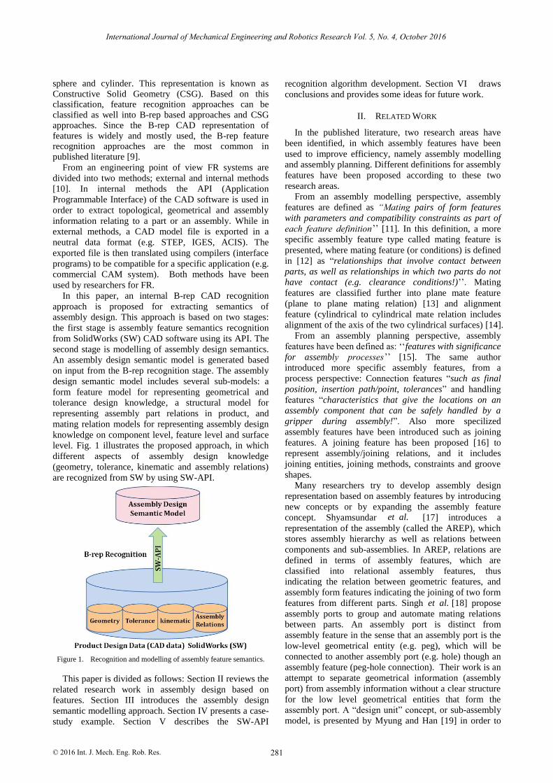
level. Fig. 1 illustrates the proposed approach, in which
different aspects of assembly design knowledge
(geometry, tolerance, kinematic and assembly relations)
are recognized from SW by using SW-API.
Figure 1. Recognition and modelling of assembly feature semantics.
This paper is divided as follows: Section II reviews the
related research work in assembly design based on
features. Section III introduces the assembly design
semantic modelling approach. Section IV presents a case-
study example. Section V describes the SW-API
recognition algorithm development. Section VI draws
conclusions and provides some ideas for future work.
II. RELATED WORK
In the published literature, two research areas have
been identified, in which assembly features have been
used to improve efficiency, namely assembly modelling
and assembly planning. Different definitions for assembly
features have been proposed according to these two
research areas.
From an assembly modelling perspective, assembly
features are defined as “Mating pairs of form features
with parameters and compatibility constraints as part of
[11]. In this definition, a more
specific assembly feature type called mating feature is
presented, where mating feature (or conditions) is defined
in [12] as “relationships that involve contact between
parts, as well as relationships in which two parts do not
have contact (e.g. clearance conditions!) Mating
features are classified further into plane mate feature
(plane to plane mating relation) [13] and alignment
feature (cylindrical to cylindrical mate relation includes
alignment of the axis of the two cylindrical surfaces) [14].
From an assembly planning perspective, assembly
features have been defined as: ‘‘features with significance
for assembl [15]. The same author
introduced more specific assembly features, from a
process perspective: Connection features “such as final
position, insertion path/point, tolerances” and handling
features “characteristics that give the locations on an
assembly component that can be safely handled by a
gripper during assembly!”. Also more specilized
assembly features have been introduced such as joining
features. A joining feature has been proposed [16] to
represent assembly/joining relations, and it includes
joining entities, joining methods, constraints and groove
shapes.
Many researchers try to develop assembly design
representation based on assembly features by introducing
new concepts or by expanding the assembly feature
[17] introduces a
representation of the assembly (called the AREP), which
stores assembly hierarchy as well as relations between
components and sub-assemblies. In AREP, relations are
defined in terms of assembly features, which are
classified into relational assembly features, thus
indicating the relation between geometric features, and
assembly form features indicating the joining of two form
features from d 18] propose
assembly ports to group and automate mating relations
between parts. An assembly port is distinct from
assembly feature in the sense that an assembly port is the
low-level geometrical entity (e.g. peg), which will be
connected to another assembly port (e.g. hole) though an
assembly feature (peg-hole connection). Their work is an
attempt to separate geometrical information (assembly
port) from assembly information without a clear structure
for the low level geometrical entities that form the
assembly port. A “design unit” concept, or sub-assembly
model, is presented by Myung and Han [19] in order to
International Journal of Mechanical Engineering and Robotics Research Vol. 5, No. 4, October 2016
281© 2016 Int. J. Mech. Eng. Rob. Res.
each feature definition
’’.
’’
y processes’’
concept. Shyamsundar
ifferent parts. Singh [
et al.
et al.
capture more knowledge about the relation between form
features in part assembly and functional design features.
A semantic modelling approach is proposed by [20] in the
SPIFF system. SPIFF is a web-based, collaborative
modelling system based on multiple-view feature
modelling [21]. In this approach, a feature is described
over a well-defined meaning, or semantics, specified in
classes. The classes specify the properties of the features
as structured instances. According to [22], in the semantic
approach the whole modelling process is “uniformly
carried out in terms of features and their entities” (e.g.
faces and parameters), and of constraints among these
entities. Users can define their own feature classes based
on existing feature classes. Feature classes are then stored
in feature libraries, from which new features can be
instantiated during a modelling session. The most
important characteristic of the semantic feature modelling,
beside its adaptability in defining new feature classes, is
that the semantics of all features is “effectively
maintained throughout model evolution”. These
characteristics of the semantic feature modelling lead to a
two-level structure in the semantic feature model, clearly
modelling entities (entities on which all
modelling operations are performed)” from entities in
“the evaluated geometric representation of the product
model
are presented in [22].
An assembly semantic modelling approach is proposed
in [23] and [24]. In this approach assembly semantics is
defined as the abstract description of assembly
relationships, which implies the constraint between parts,
assembly rule, assembly knowledge and assembly action
[24]. The proposed assembly semantic model includes the
joint relation, position relation and transmission relation
of the assembly. According to [23], the benefits of
assembly semantic modelling are simplified interaction
and capturing of design intention, expressing rich
assembly constraints (position constraint; dimensional
constraint, kinematics constraint) and implying assembly
precedence relationship knowledge.
A more detailed assembly semantic modelling
approach is presented by Hui et al. [25], where assembly
information is described by a three-level semantic
abstraction: conceptual level, structural level and part
level. Ma and Tong [26] expand the assembly feature
concept by proposing a semantic feature concept
including so called associative features (AFs), An
associative feature is “a set of semantic relationships
among product geometric entities, which can be defined
as a single object entity in an engineering application”
[26]. As a conclusion from this section, three points have to
be taken into consideration in modelling assembly
features for process planning:
Assembly feature semantics should include
geometrical, non-geometrical, functional and
assembly relations.
The assembly feature concept must be further
specified by mating features. Mating features have
to further “expand” to include more details about
geometrical entities by defining joining features.
Mating and joining features are essential for
specifying assembly process planning, since
joining processes will take place on mating
entities.
It is preferable to separate geometrical knowledge
from assembly knowledge to enable more options
for designers, in the detailed design phase, for
changing geometry while keeping the assembly
information.
III. ASSEMBLY DESIGN SEMANTIC MODEL
Based on the literature study in the previous two
sections, the assembly design semantic model generated
from the B-rep recognition stage should include full
description about assembly design in order to determine
the required assembly processes and resources in APP.
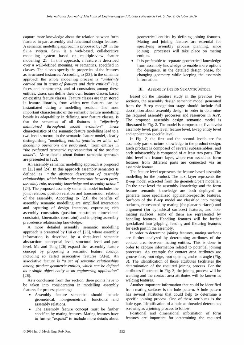
The proposed assembly design semantic model is
illustrated in Fig. 2. The model is composed of five levels:
assembly level, part level, feature level, B-rep entity level
and application specific level.
In Fig. 2, the first and the second levels are for
assembly part structure knowledge in the product design.
Each product is composed of several subassemblies, and
each subassembly is composed of at least two parts. The
third level is a feature layer, where two associated form
features from different parts are connected via an
assembly feature.
The feature level represents the feature-based assembly
modelling for the product. The next layer represents the
B-rep model extracted from the geometric/part modeller.
On the next level the assembly knowledge and the form
feature semantic knowledge are both deployed to
generate more specialized application-specific features.
Surfaces of the B-rep model are classified into mating
surfaces, represented by mating (for planar surfaces) and
alignment (for cylindrical surfaces) features, and non-
mating surfaces, some of them are represented by
handling features. Handling features will be further
specialized into gripping, feeding and fixturing features
for each part in the assembly.
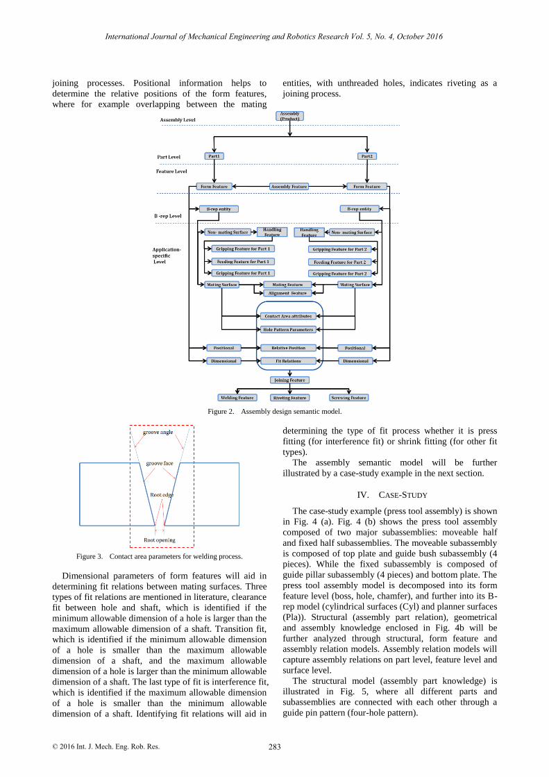
In order to determine joining features, mating surfaces
are further analyzed by determining attributes of the
contact area between mating entities. This is done in
order to capture information related to potential joining
processes. An example for contact area attributes are
groove face, root edge, root opening and root angle (Fig.
3). The identification of those attributes facilitates the
determination of the required joining process. For the
attributes illustrated in Fig. 3, the joining process will be
welding and the contact area attributes will be known as
welding features.
Another important information that could be identified
from mating surfaces is the hole pattern. A hole pattern
has several attributes that could help to determine a
specific joining process. One of these attributes is the
hole type. Identification of a hole as threaded determines
screwing as a joining process to follow.
Positional and dimensional information of form
features are important for determining the required
International Journal of Mechanical Engineering and Robotics Research Vol. 5, No. 4, October 2016
282© 2016 Int. J. Mech. Eng. Rob. Res.
distinguishing “
“
”. More details about feature semantic approach
”
joining processes. Positional information helps to
determine the relative positions of the form features,
where for example overlapping between the mating
entities, with unthreaded holes, indicates riveting as a
joining process.
Figure 2. Assembly design semantic model.
Figure 3. Contact area parameters for welding process.
Dimensional parameters of form features will aid in
determining fit relations between mating surfaces. Three
types of fit relations are mentioned in literature, clearance
fit between hole and shaft, which is identified if the
minimum allowable dimension of a hole is larger than the
maximum allowable dimension of a shaft. Transition fit,
which is identified if the minimum allowable dimension
of a hole is smaller than the maximum allowable
dimension of a shaft, and the maximum allowable
dimension of a hole is larger than the minimum allowable
dimension of a shaft. The last type of fit is interference fit,
which is identified if the maximum allowable dimension
of a hole is smaller than the minimum allowable
dimension of a shaft. Identifying fit relations will aid in
determining the type of fit process whether it is press
fitting (for interference fit) or shrink fitting (for other fit
types).
The assembly semantic model will be further
illustrated by a case-study example in the next section.
IV. CASE-STUDY
The case-study example (press tool assembly) is shown
in Fig. 4 (a). Fig. 4 (b) shows the press tool assembly
composed of two major subassemblies: moveable half
and fixed half subassemblies. The moveable subassembly
is composed of top plate and guide bush subassembly (4
pieces). While the fixed subassembly is composed of
guide pillar subassembly (4 pieces) and bottom plate. The
press tool assembly model is decomposed into its form
feature level (boss, hole, chamfer), and further into its B-
rep model (cylindrical surfaces (Cyl) and planner surfaces
(Pla)). Structural (assembly part relation), geometrical
and assembly knowledge enclosed in Fig. 4b will be
further analyzed through structural, form feature and
assembly relation models. Assembly relation models will
capture assembly relations on part level, feature level and
surface level.
The structural model (assembly part knowledge) is
illustrated in Fig. 5, where all different parts and
subassemblies are connected with each other through a
guide pin pattern (four-hole pattern).
International Journal of Mechanical Engineering and Robotics Research Vol. 5, No. 4, October 2016
283© 2016 Int. J. Mech. Eng. Rob. Res.
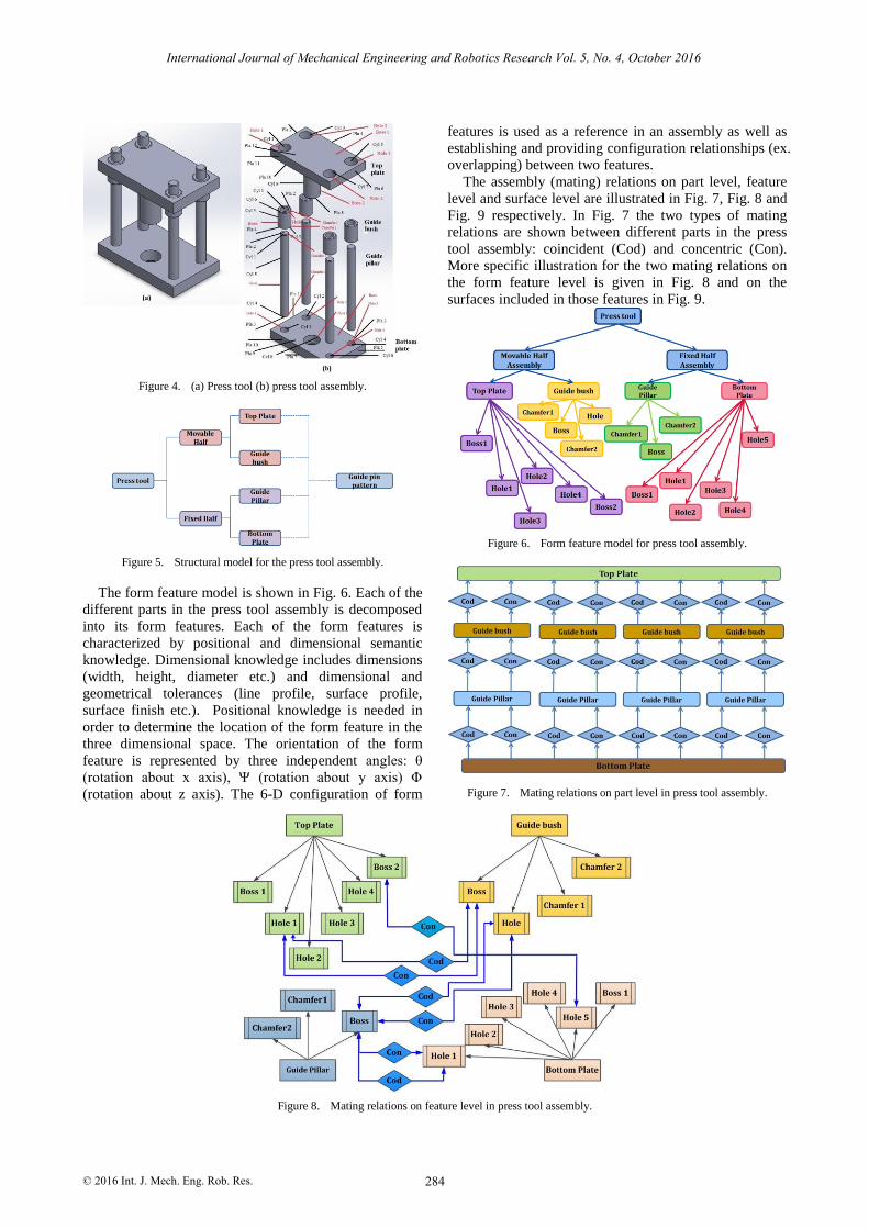
Figure 4. (a) Press tool (b) press tool assembly.
Figure 5. Structural model for the press tool assembly.
The form feature model is shown in Fig. 6. Each of the
different parts in the press tool assembly is decomposed
into its form features. Each of the form features is
characterized by positional and dimensional semantic
knowledge. Dimensional knowledge includes dimensions
(width, height, diameter etc.) and dimensional and
geometrical tolerances (line profile, surface profile,
surface finish etc.). Positional knowledge is needed in
order to determine the location of the form feature in the
three dimensional space. The orientation of the form
feature is represented by three independent angles: θ
(rotation about x axis), Ψ (rotation about y axis) Φ
(rotation about z axis). The 6-D configuration of form
features is used as a reference in an assembly as well as
establishing and providing configuration relationships (ex.
overlapping) between two features.
The assembly (mating) relations on part level, feature
level and surface level are illustrated in Fig. 7, Fig. 8 and
Fig. 9 respectively. In Fig. 7 the two types of mating
relations are shown between different parts in the press
tool assembly: coincident (Cod) and concentric (Con).
More specific illustration for the two mating relations on
the form feature level is given in Fig. 8 and on the
surfaces included in those features in Fig. 9.
Figure 6. Form feature model for press tool assembly.
Figure 7. Mating relations on part level in press tool assembly.
Figure 8. Mating relations on feature level in press tool assembly.
International Journal of Mechanical Engineering and Robotics Research Vol. 5, No. 4, October 2016
284© 2016 Int. J. Mech. Eng. Rob. Res.
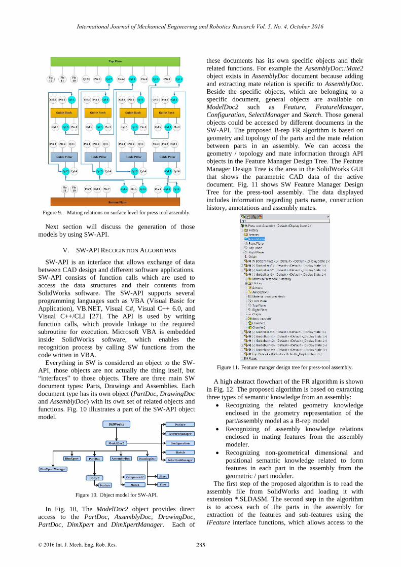
Figure 9. Mating relations on surface level for press tool assembly.
Next section will discuss the generation of those
models by using SW-API.
V. SW-API RECOGINTION ALGORITHMS
SW-API is an interface that allows exchange of data
between CAD design and different software applications.
SW-API consists of function calls which are used to
access the data structures and their contents from
SolidWorks software. The SW-API supports several
programming languages such as VBA (Visual Basic for
Application), VB.NET, Visual C#, Visual C++ 6.0, and
Visual C++/CLI [27]. The API is used by writing
function calls, which provide linkage to the required
subroutine for execution. Microsoft VBA is embedded
inside SolidWorks software, which enables the
recognition process by calling SW functions from the
code written in VBA.
Everything in SW is considered an object to the SW-
API, those objects are not actually the thing itself, but
“interfaces” to those objects. There are three main SW
document types: Parts, Drawings and Assemblies. Each
document type has its own object (PartDoc, DrawingDoc
and AssemblyDoc) with its own set of related objects and
functions. Fig. 10 illustrates a part of the SW-API object
model.
Figure 10. Object model for SW-API.
In Fig. 10, The ModelDoc2 object provides direct
access to the PartDoc, AssemblyDoc, DrawingDoc,
PartDoc, DimXpert and DimXpertManager. Each of
these documents has its own specific objects and their
related functions. For example the AssemblyDoc::Mate2
object exists in AssemblyDoc document because adding
and extracting mate relation is specific to AssemblyDoc.
Beside the specific objects, which are belonging to a
specific document, general objects are available on
ModelDoc2 such as Feature, FeatureManager,
Configuration, SelectManager and Sketch. Those general
objects could be accessed by different documents in the
SW-API. The proposed B-rep FR algorithm is based on
geometry and topology of the parts and the mate relation
between parts in an assembly. We can access the
geometry / topology and mate information through API
objects in the Feature Manager Design Tree. The Feature
Manager Design Tree is the area in the SolidWorks GUI
that shows the parametric CAD data of the active
document. Fig. 11 shows SW Feature Manager Design
Tree for the press-tool assembly. The data displayed
includes information regarding parts name, construction
history, annotations and assembly mates.
Figure 11. Feature manger design tree for press-tool assembly.
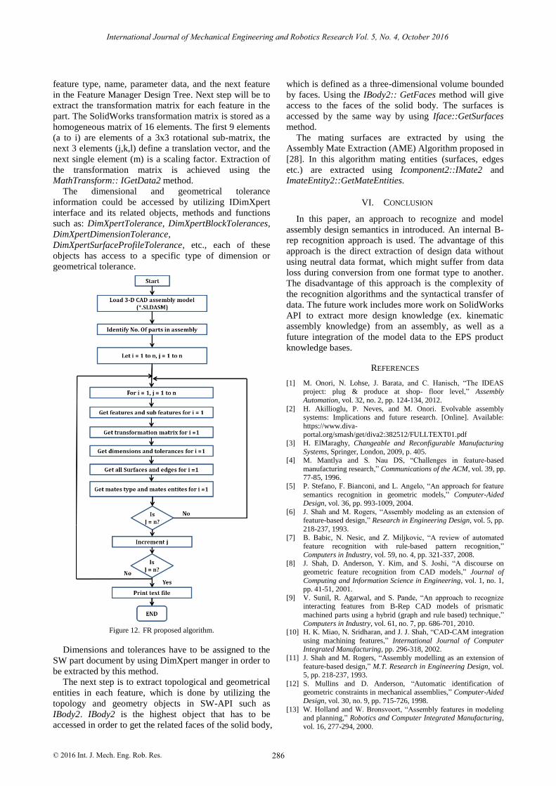
A high abstract flowchart of the FR algorithm is shown
in Fig. 12. The proposed algorithm is based on extracting
three types of semantic knowledge from an assembly:
Recognizing the related geometry knowledge
enclosed in the geometry representation of the
part/assembly model as a B-rep model
Recognizing of assembly knowledge relations
enclosed in mating features from the assembly
modeler.
Recognizing non-geometrical dimensional and
positional semantic knowledge related to form
features in each part in the assembly from the
geometric / part modeler.
The first step of the proposed algorithm is to read the
assembly file from SolidWorks and loading it with
extension *.SLDASM. The second step in the algorithm
is to access each of the parts in the assembly for
extraction of the features and sub-features using the
IFeature interface functions, which allows access to the
International Journal of Mechanical Engineering and Robotics Research Vol. 5, No. 4, October 2016
285© 2016 Int. J. Mech. Eng. Rob. Res.
feature type, name, parameter data, and the next feature
in the Feature Manager Design Tree. Next step will be to
extract the transformation matrix for each feature in the
part. The SolidWorks transformation matrix is stored as a
homogeneous matrix of 16 elements. The first 9 elements
(a to i) are elements of a 3x3 rotational sub-matrix, the
next 3 elements (j,k,l) define a translation vector, and the
next single element (m) is a scaling factor. Extraction of
the transformation matrix is achieved using the
MathTransform:: IGetData2 method.
The dimensional and geometrical tolerance
information could be accessed by utilizing IDimXpert
interface and its related objects, methods and functions
such as: DimXpertTolerance, DimXpertBlockTolerances,
DimXpertDimensionTolerance,
DimXpertSurfaceProfileTolerance, etc., each of these
objects has access to a specific type of dimension or
geometrical tolerance.
Figure 12. FR proposed algorithm.
Dimensions and tolerances have to be assigned to the
SW part document by using DimXpert manger in order to
be extracted by this method.
The next step is to extract topological and geometrical
entities in each feature, which is done by utilizing the
topology and geometry objects in SW-API such as
IBody2. IBody2 is the highest object that has to be
accessed in order to get the related faces of the solid body,
which is defined as a three-dimensional volume bounded
by faces. Using the IBody2:: GetFaces method will give
access to the faces of the solid body. The surfaces is
accessed by the same way by using Iface::GetSurfaces
method.
The mating surfaces are extracted by using the
Assembly Mate Extraction (AME) Algorithm proposed in
[28]. In this algorithm mating entities (surfaces, edges
etc.) are extracted using Icomponent2::IMate2 and
ImateEntity2::GetMateEntities.
VI. CONCLUSION
In this paper, an approach to recognize and model
assembly design semantics in introduced. An internal B-
rep recognition approach is used. The advantage of this
approach is the direct extraction of design data without
using neutral data format, which might suffer from data
loss during conversion from one format type to another.
The disadvantage of this approach is the complexity of
the recognition algorithms and the syntactical transfer of
data. The future work includes more work on SolidWorks
API to extract more design knowledge (ex. kinematic
assembly knowledge) from an assembly, as well as a
future integration of the model data to the EPS product
knowledge bases.
REFERENCES
[1] M. Onori, N. Lohse, J. Barata, and C. Hanisch, “The IDEAS project: plug & produce at shop- floor level,” Assembly
Automation, vol. 32, no. 2, pp. 124-134, 2012.
[2] H. Akillioglu, P. Neves, and M. Onori. Evolvable assembly systems: Implications and future research. [Online]. Available:
https://www.diva-portal.org/smash/get/diva2:382512/FULLTEXT01.pdf
[3] H. ElMaraghy, Changeable and Reconfigurable Manufacturing
Systems, Springer, London, 2009, p. 405. [4] M. Mantlya and S. Nau DS, “Challenges in feature-based
manufacturing research,” Communications of the ACM, vol. 39, pp. 77-85, 1996.
[5] P. Stefano, F. Bianconi, and L. Angelo, “An approach for feature
semantics recognition in geometric models,” Computer-Aided Design, vol. 36, pp. 993-1009, 2004.
[6] J. Shah and M. Rogers, “Assembly modeling as an extension of feature-based design,” Research in Engineering Design, vol. 5, pp.
218-237, 1993.
[7] B. Babic, N. Nesic, and Z. Miljkovic, “A review of automated feature recognition with rule-based pattern recognition,”
Computers in Industry, vol. 59, no. 4, pp. 321-337, 2008. [8] J. Shah, D. Anderson, Y. Kim, and S. Joshi, “A discourse on
geometric feature recognition from CAD models,” Journal of
Computing and Information Science in Engineering, vol. 1, no. 1, pp. 41-51, 2001.
[9] V. Sunil, R. Agarwal, and S. Pande, “An approach to recognize interacting features from B-Rep CAD models of prismatic
machined parts using a hybrid (graph and rule based) technique,”
Computers in Industry, vol. 61, no. 7, pp. 686-701, 2010. [10] H. K. Miao, N. Sridharan, and J. J. Shah, “CAD-CAM integration
using machining features,” International Journal of Computer Integrated Manufacturing, pp. 296-318, 2002.
[11] J. Shah and M. Rogers, “Assembly modelling as an extension of
feature-based design,” M.T. Research in Engineering Design, vol. 5, pp. 218-237, 1993.
[12] S. Mullins and D. Anderson, “Automatic identification of
geometric constraints in mechanical assemblies,” Computer-Aided
Design, vol. 30, no. 9, pp. 715-726, 1998.
[13] W. Holland and W. Bronsvoort, “Assembly features in modeling and planning,” Robotics and Computer Integrated Manufacturing,
vol. 16, 277-294, 2000.
International Journal of Mechanical Engineering and Robotics Research Vol. 5, No. 4, October 2016
286© 2016 Int. J. Mech. Eng. Rob. Res.
[14] J. Shah, “Designing with parametric CAD: Classification and comparison of construction techniques,” Geometric Modelling:
Theoretical and Computational Basis Towards Advanced CAD
Applications, vol. 75, pp. 53-68, 2001. [15] W. Van Holland, “Assembly features in modelling and planning,”
Ph.D. dissertation, Delft: Delft University of Technology, 1997. [16] K. Kim, “Assembly operation tools for. Assembly operation tools
for e product design and realization,” Ph.D. dissertation,
Pittsburgh: University of Pittsburgh, 2003. [17] N. Shyamsundar and R. Gadh, “Internet-based collaborative
product design with assembly features and virtual design spaces,” Computer-Aided Design, vol. 33, pp. 637-651, 2001.
[18] P. Singh and B. Bettig, “Port-compatibility and connectability
based assembly design,” Journal of Computing and Information Science in Engineering, vol. 4, pp. 197-205, 2004.
[19] S. Myung and S. Han, “Knowledge-based parametric design of mechanical products based on configuration design method,”
Expert Systems with Applications, vol. 21, no. 2, pp. 99-107, 2001.
[20] W. Bronsvoort, R. Bidarra, M. Dohmen, W. Van Holland, and K. de Kraker, “Multiple-view feature modelling and conversion,” in
Geometric Modelling: Theory and Practice— the State of the Art, Berlin, Springer, 1997, pp. 159-174.
[21] E. Van den Berg, R. Bidarra, and W. Bronsvoort, “Web-based
interaction on feature models,” in Proc. the Seventh IFIP WG 5.2
International Workshop on Geometric Modelling: Fundamentals and Applications, 2000, pp. 113-123.
[22] R. Bidarra and W. F. Bronsvoort, “Semantic feature modelling,”
Computer-Aided Design, vol. 32, no. 3, pp. 201-225, 2000. [23] J. Tan, L. Zhenyu, and Z. Shuyou, “Intelligent assembly modeling
based on semantics knowledge in virtual environment,” in Proc. the International Conference on Computer Supported Cooperative
Work in Design, 2002, pp. 568-571.
[24] L. Zhen-Yu, T. Jian-Rong, Z. Shu-You, and J. Zheng-Feng, “Design semantics of assembly modeling in virtual environment:
expression, transfer and transformation,” Chinese Journal of Computers, vol. 23, no. 11, pp. 1208-1214, 2000.
[25] W. Hui, X. Dong, D. Guanghong, and Z. Linxuan, “Assembly
planning based on semantic modeling approach,” Computers in Industry, vol. 58, no. 3, pp. 227-239, 2007.
[26] Y. S. Ma and T. Tong, “Associative feature modeling for concurrent engineering integration,” Computers in Industry, vol.
51, no. 1, pp. 51-71, 2003.
[27] Help 2016 S. A., 2016, [Online]. Available: http://help.solidworks.com/2016/English/api/sldworksapiprogguid
e/Welcome.htm [28] A. Mathew, “A novel method of using API to generate liaison
relationships from an assembly,” International Journal of
Software Engineering and Applications, vol. 1, no. 3, pp. 167-175, 2010.
International Journal of Mechanical Engineering and Robotics Research Vol. 5, No. 4, October 2016
287© 2016 Int. J. Mech. Eng. Rob. Res.