Embed Size (px)
Citation preview

Hybrid Pantorouter Assembly Guide
Page 1 of 30
Hybrid PantoRouter Assembly Guide Very special thanks to Sven and Kathy Claessens, our Hybrid PantoRouter distributor for Europe, and to Jim Lindauer who so kindly documented the assembly of his Hybrid PantoRouter and added content to this guide. While most of the assembly is the same for the European and US versions of the HPR, the table support is slightly different and this guide only applies to the U.S. version. In addition to this written assembly guide, there are some videos on the http://hybridpantorouter.com website which might be helpful and enjoyable to
watch. Since Kuldeep Singh is constantly improving the HPR and adding accessories, the documentation will continue to evolve so please check the Support pages and the Forum of the website to see what’s new. Lastly, we’re fans of Loctite or a similar thread lock compound. We use it liberally on all bolts and cap screws except those on the moving parts of the plunge lever handle and the depth stoppers. Dry assembly and alignment would be wise before applying Loctite one screw at a time. Always adhere to the Warnings and Safety Guidelines from your router manufacturer and those written on the placard on the Hybrid PantoRouter. Work safely around all power tools so you can enjoy a long and healthy hobby or career in woodworking.
Enjoy your assembly and please call or email if you have questions along the way. [email protected] 877-‐333-‐7150
Hybrid Pantorouter Assembly Guide
Page 2 of 30
To reduce the risk of injury, the user must:
• Read and understand the operator's manual before operating product. • Wear eye protection, earplugs and dust mask. • Do not wear gloves, neckties, jewelry or loose clothing. Contain long hair. • Know how to shut off router in an emergency. • Disconnect router from power source before servicing or changing router bit. Do not adjust the router until it has been disconnected from power.
• Securely mount the router in mounting bracket before turning power on. If router motor cannot be securely mounted as described in the assembly instructions, do not use the PantoRouter.
• Clamp material to be cut securely to platform before starting router. • Keep hands and clothing away from spinning router bit. • Do not operate this machine while under the influence of alcohol or drugs. • When servicing, use only identical parts.
Failure to comply with these warnings may result in serious personal injury.
NOTE : The template side is considered the back of the apparatus and the table is the front even though in ordinary use the template will be to your left and the table to your right. Some of the descriptions in the original document have been changed to follow this convention. The operator side places the template to your left and the table to your right.
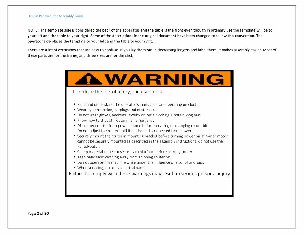
There are a lot of extrusions that are easy to confuse. If you lay them out in decreasing lengths and label them, it makes assembly easier. Most of these parts are for the frame, and three sizes are for the sled.
Hybrid Pantorouter Assembly Guide
Page 3 of 30
Hybrid Pantorouter Assembly Guide
Page 4 of 30
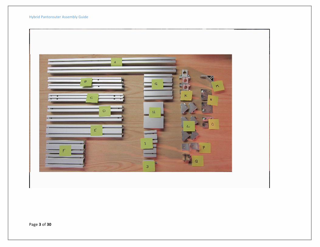
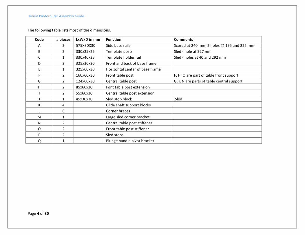
The following table lists most of the dimensions.
Code # pieces LxWxD in mm Function Comments A 2 575X30X30 Side base rails Scored at 240 mm, 2 holes @ 195 and 225 mm B 2 330x25x25 Template posts Sled -‐ hole at 227 mm C 1 330x40x25 Template holder rail Sled -‐ holes at 40 and 292 mm D 2 325x30x30 Front and back of base frame E 1 325x60x30 Horizontal center of base frame F 2 160x60x30 Front table post F, H, O are part of table front support G 2 124x60x30 Central table post G, I, N are parts of table central support H 2 85x60x30 Font table post extension I 2 55x60x30 Central table post extension J 1 45x30x30 Sled stop block Sled K 4 Glide shaft support blocks L 6 Corner braces M 1 Large sled corner bracket N 2 Central table post stiffener O 2 Front table post stiffener P 2 Sled stops Q 1 Plunge handle pivot bracket

Hybrid Pantorouter Assembly Guide
Page 5 of 30
Base Frame Assembly
These are all the parts you will need for this stage of assembly.
Slide the glide shaft brackets K into the E center rail in the slot closest to the D back rail. The bolt cap should be on the inside of the frame so you have easy access later to tighten them after installing the shafts. The orientation on the back rail isn’t important since access is not restricted. Next, slip in an angle bracket L into either end of the rail.
Hybrid Pantorouter Assembly Guide
Page 6 of 30
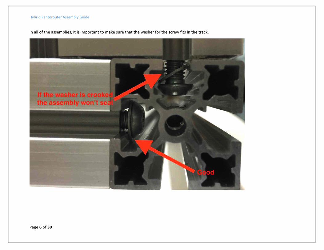
In all of the assemblies, it is important to make sure that the washer for the screw fits in the track.

Hybrid Pantorouter Assembly Guide
Page 7 of 30
Next insert one nut from two of the angle brackets into the center rail slot opposite the glide support bracket slot.
Then slide the center rail onto the sides, making sure the screws and washers fit.
Find the scribed line on the A sides (closer to the front than the back). The back of the center rail needs to align with these scribe lines.
Install the front supports for the table (F). Slide one hex head screw into the front horizontal cross rail (D) and the other hex head screw into the side rail (A). Make sure the washers are inside the slots. Repeat for both sides of the frame.

Hybrid Pantorouter Assembly Guide
Page 8 of 30
Assemble the central table support post (Parts G, I, N) including the angle bracket with the nut already in the center crosspiece track:

Hybrid Pantorouter Assembly Guide
Page 9 of 30
Slide the central table support posts onto the side rail D making sure that the washers are inside the T-‐slot.

Hybrid Pantorouter Assembly Guide
Page 10 of 30
Align the central table support posts exactly to the scribed line ion the side rails and slightly snug the screws. Now slide the remaining two glide shaft bearings onto the back horizontal rail (D) and attach the remaining angle brackets.
Slide the cross rail onto the side rails and lightly tighten everything. This is not the final alignment of parts so avoid use of Loctite at this stage.
You can install the rubber feet with the thin screws into the (small) holes in the bottom of the frame. Do not overtighten the rubber feet. They can get brittle if they’re too tight.

Hybrid Pantorouter Assembly Guide
Page 11 of 30
Sled Assembly Most of the pantograph comes assembled but you have to attach the bearing blocks and the plunge lever.
If the bottom of the sled has paper, remove it before the bearings are attached.

Hybrid Pantorouter Assembly Guide
Page 12 of 30
Template holder frame Parts B and C are used to assemble the template holder frame. The plunge lever (with the handle), a large corner angle (M) a pivot bracket (Q), a stop block (J) and stops (P) are also used.
Slip the horizontal top rail (C) into the slots of the template holder support posts. These are square and if the screws are loosened can be pulled out with a screwdriver to fit in the T-‐slots.

Hybrid Pantorouter Assembly Guide
Page 13 of 30
Align the post and rail so they’re flush at the top then tighten the screws to secure the horizontal template rail.
Slide the large corner bracket M onto the template post on the operator (left) side and attach with the hex head screws.

Hybrid Pantorouter Assembly Guide
Page 14 of 30
The Pantograph sled assembly is complete and ready to mate to the guide rails on the base frame. The guide rail supports should be loose and easily movable for the glide shaft installation.
Slide the glide shafts one at a time through the rear (template side) shaft supports, the linear bearings in the pantograph sled and into the shaft support on the central cross rail.
Position the shaft supports equidistant from the side rails and check to make sure that the sled contacts both table support posts equally when you slide it forward. There will be a very small gap between the supports and the side rails. Tighten the support screws

Hybrid Pantorouter Assembly Guide
Page 15 of 30
Depth Stoppers There are two of these stops (P).
Only one of these is shown installed

Hybrid Pantorouter Assembly Guide
Page 16 of 30
Installation of plunge lever pivot bracket and plunge lever handle Install the plunge handle pivot bracket (Q) to side rail D on the operator side at the rear.
The plunge lever linkage arms have a countersunk hole on one side. Attach the arms with a screw and nut. Do not over tighten. The plunge lever arm should move freely.
Attach the base of the plunge lever to pivot bracket previously installed. Do not over tighten. The plunge lever arm should move freely
Hybrid Pantorouter Assembly Guide
Page 17 of 30
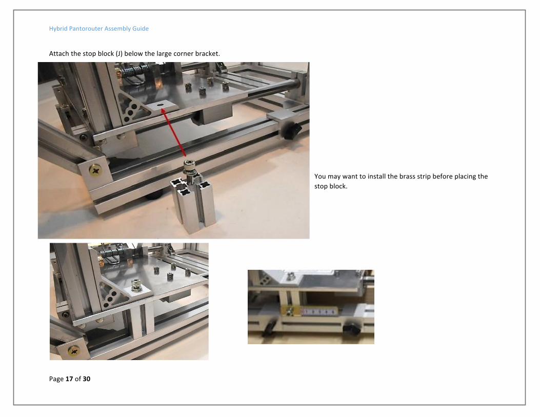
Attach the stop block (J) below the large corner bracket.
You may want to install the brass strip before placing the stop block.
Hybrid Pantorouter Assembly Guide
Page 18 of 30
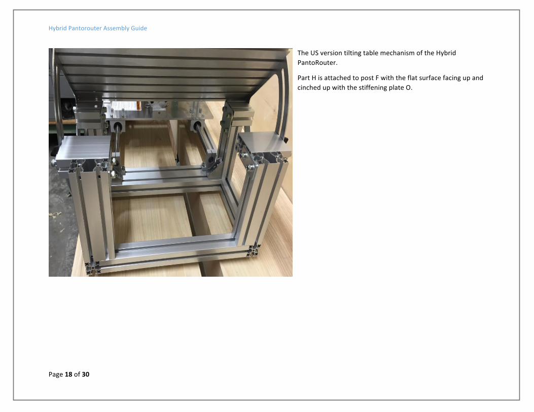
The US version tilting table mechanism of the Hybrid PantoRouter.
Part H is attached to post F with the flat surface facing up and cinched up with the stiffening plate O.
Hybrid Pantorouter Assembly Guide
Page 19 of 30
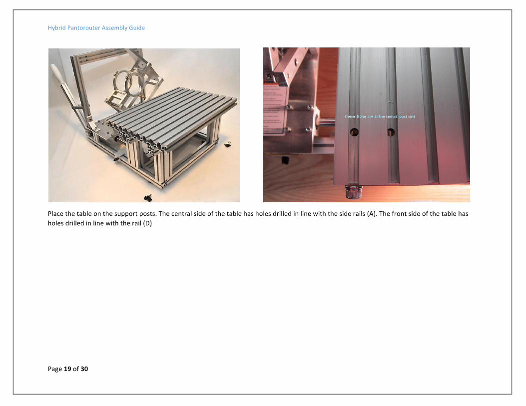
Place the table on the support posts. The central side of the table has holes drilled in line with the side rails (A). The front side of the table has holes drilled in line with the rail (D)

Hybrid Pantorouter Assembly Guide
Page 20 of 30
Attach the tilt plates to the central posts with a small washer between the tilt plate and the post (the screw already has a washer on the outside).
Attach the tilt plates to the table using large hex head screws with a lock washer.
Hybrid Pantorouter Assembly Guide
Page 21 of 30
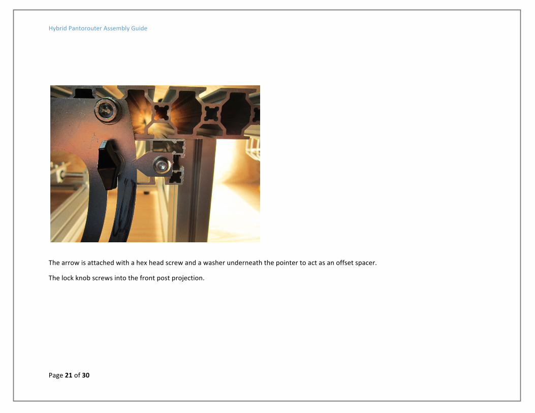
The arrow is attached with a hex head screw and a washer underneath the pointer to act as an offset spacer.
The lock knob screws into the front post projection.

Hybrid Pantorouter Assembly Guide
Page 22 of 30
Remove the protective covering (if present) from the front of the template and slide the brass sliders into the template posts. You may have to loosen the screws to get this to slide easily.

Hybrid Pantorouter Assembly Guide
Page 23 of 30
Attach the red knobs from the back and the wing nuts to the bottom of the brass sliders.

Hybrid Pantorouter Assembly Guide
Page 24 of 30
The finished Hybrid PantoRouter with router installed and optional Bessey clamps.
Next step is to watch the alignment video https://www.youtube.com/watch?v=rlRhgHjU6Bw
Hybrid Pantorouter Assembly Guide
Page 25 of 30
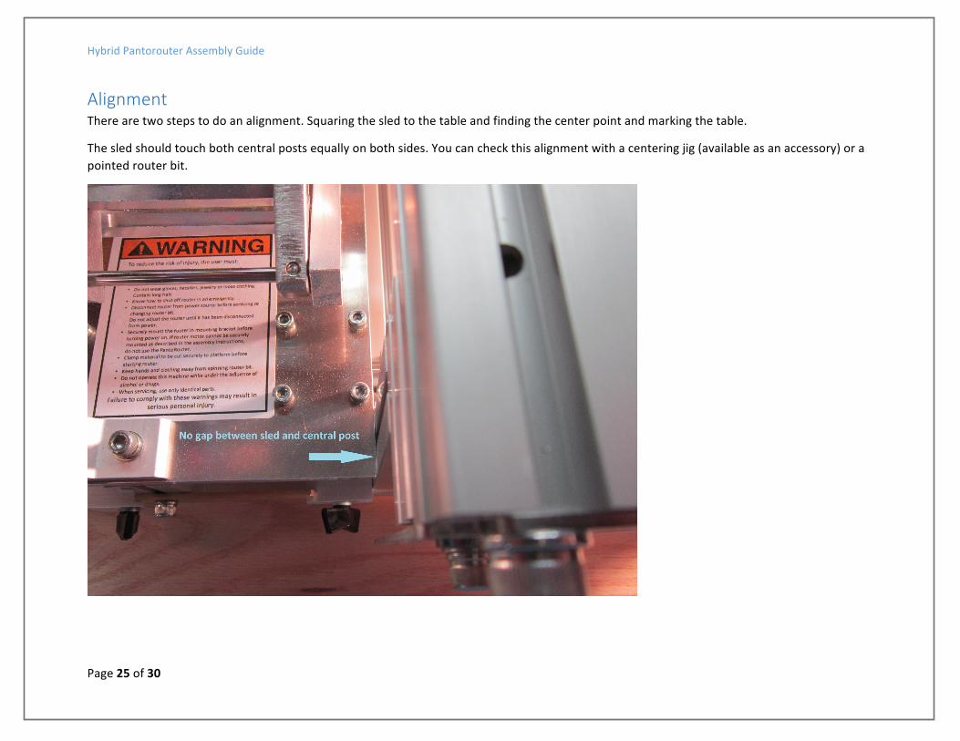
Alignment There are two steps to do an alignment. Squaring the sled to the table and finding the center point and marking the table.
The sled should touch both central posts equally on both sides. You can check this alignment with a centering jig (available as an accessory) or a pointed router bit.
Hybrid Pantorouter Assembly Guide
Page 26 of 30
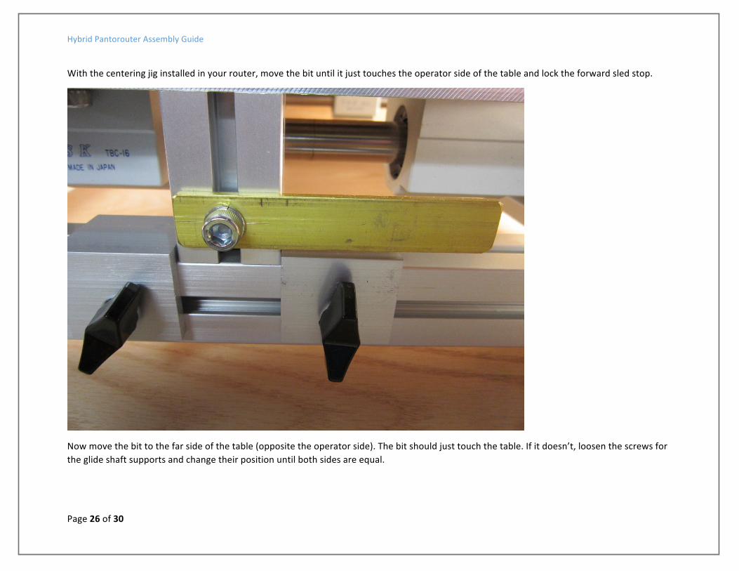
With the centering jig installed in your router, move the bit until it just touches the operator side of the table and lock the forward sled stop.
Now move the bit to the far side of the table (opposite the operator side). The bit should just touch the table. If it doesn’t, loosen the screws for the glide shaft supports and change their position until both sides are equal.
Hybrid Pantorouter Assembly Guide
Page 27 of 30
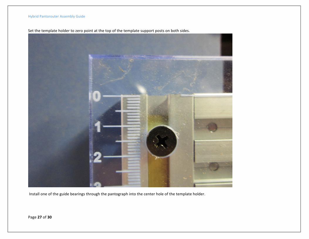
Set the template holder to zero point at the top of the template support posts on both sides.
Install one of the guide bearings through the pantograph into the center hole of the template holder.

Hybrid Pantorouter Assembly Guide
Page 28 of 30
Tighten the white knob to hold the bearing shaft in place.

Hybrid Pantorouter Assembly Guide
Page 29 of 30
Move the plunge handle to position the centering jig at the center of the table.
Use an awl or knife to score the centerline of the table. You will use this line to center your work piece with every setup of the HPR so make it clearly visible, square to the table and permanent.
Hybrid Pantorouter Assembly Guide
Page 30 of 30
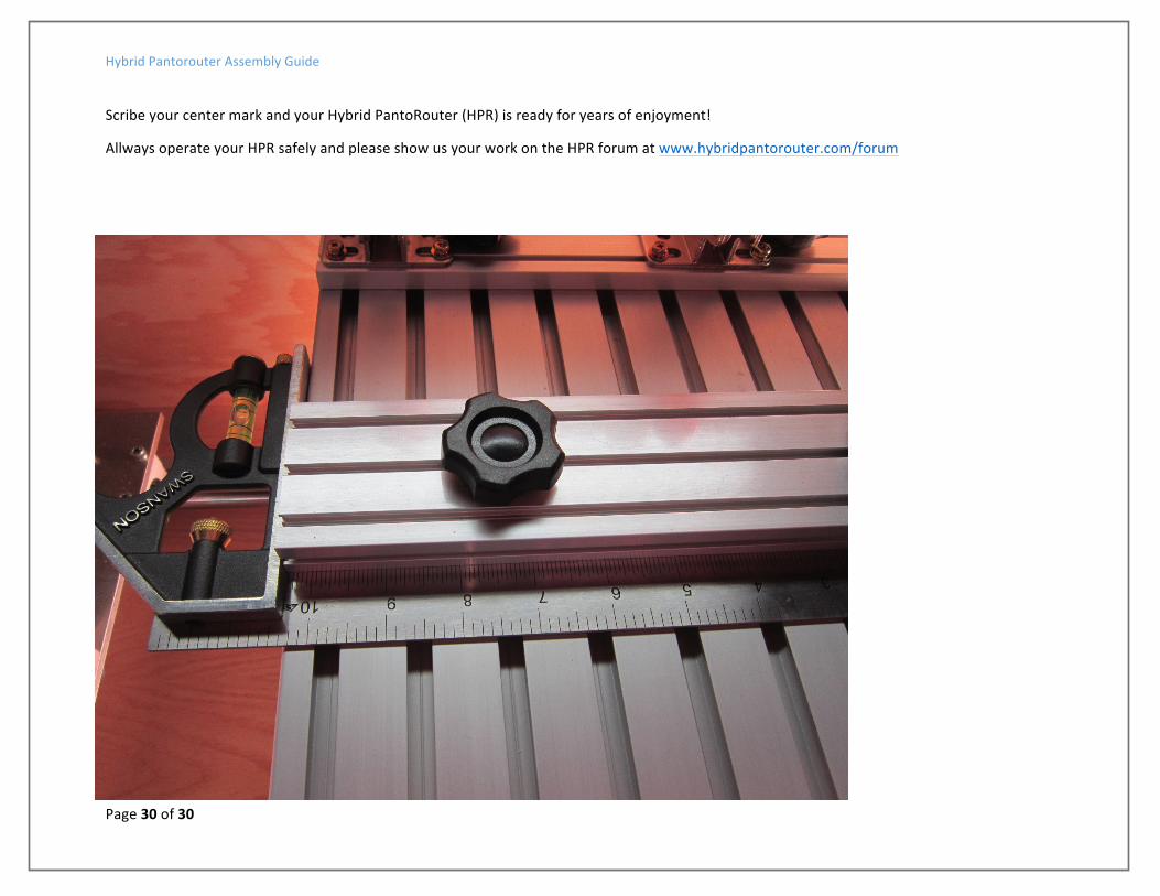
Scribe your center mark and your Hybrid PantoRouter (HPR) is ready for years of enjoyment!
Allways operate your HPR safely and please show us your work on the HPR forum at www.hybridpantorouter.com/forum