Embed Size (px)
Citation preview

1Revision date: 10.13.20
©2020 ClearSpan™All Rights Reserved. Reproduction is prohibited without permission.
Assembly Guide forOver-The-Top Blackout System
ATTENTION: This guide describes the assembly and installation of an over-the-top roll-up curtain system. The design flexibility of this curtain system allows for installation on a variety of possible shelters. The examples in this guide present basic assembly and installation information. Actual shelter and curtain tube system may resemble what is presented, but differ in details. Adjust as needed.

2 RBC57L36_48_60_72_84_96 Revision date: 10.13.20
SAFETY PRECAUTIONS
• Wear eye protection.
• Wear head protection.
• Wear gloves when handling the pipe and brackets.
• Use a portable GFCI when working with power tools and cords.
WARNING: Exercise caution during installation. Strong winds can lift and blow the curtain during and after installation. Do not install the curtain during windy conditions or when such conditions are expected.
READ THIS DOCUMENT BEFORE YOU ASSEMBLE THE OVER-THE-TOP BLACKOUT SYSTEM.
Thank you for purchasing this Over-The-Top Blackout System. These instructions include helpful hints and important information needed to safely assemble and properly maintain the blackout system and related components. Please read these instructions before you begin. If you have any questions during assembly, contact customer service.
Important Information
REQUIRED TOOLS The following list identifies the main tools needed to assemble the blackout curtain system. Additional tools and supports may be needed depending on the structure, location, and application. We recommend at least two (2) people for assembly and more if curtain exceeds 50' in length.
• Tape measures or measuring devices.
• Variable speed drill (cordless with extra batteries works best) and drill bits (1/8" or smaller for pilot holes)
• Saw to cut metal pipe.
• Wrench and/or socket set.
• Hammer and gloves.
• Scissors or utility knife
• Ladders, work platforms, and other machinery for lifting designed to work safely at system height.
• Safety equipment to protect head, eyes, hands & feet.
ASSEMBLY PROCEDURE
Following the instructions as presented will help ensure the proper assembly of the curtain and related components. Failing to follow these steps can result in an improperly assembled curtain tube system. The steps outlining the assembly process are as follows:
1. Verify that all parts are included in the shipment. Notify Customer Service for questions or concerns.
2. Read these instructions and all additional documentation included with the shipment before you begin.
3. Gather the tools and assistants needed to assemble the over-the-top blackout system.
4. Assemble the system components in the order they are presented in these instructions.
5. Read the Care and Maintenance information.
6. Complete and return all warranty information as instructed if included.
UNPACK AND IDENTIFY PARTS
The following steps ensure you have all the necessary parts before you begin.
1. Unpack the contents of the box or boxes and place them where you can easily inventory the shipment. Refer to the Bill of Materials/Spec Sheets
2. Verify that all parts listed on the Bill of Materials/Spec Sheets are present. If you have questions or parts are missing, contact customer service. NOTE: You do not need to open the plastic bags containing smaller parts such as fasteners or washers.

3Revision date: 10.13.20 RBC57L36_48_60_72_84_96
Parts IdentificationPICTORIAL GUIDE
The following graphics and photos will help you identify the different parts of the curtain tube support system. Consult the Quick Start Guide for additional details and diagrams. (Some parts are not shown.) FA4472B/FA4477B
Tek Screws100441 and 100442 Magnetic Nut Setter
116018Roll-Up Motor
116019Roll-Up Motor Bracket
115573Channel Splice Plate
115792Roll-Up Pivot Bracket
116219Mounting Arm Fitting
CC6214Fabric Clip
ELECTRICAL WARNING Greenhouse frames are metal and will conduct electricity! Exercise caution if working around or on the frames with electric power tools. Use cordless, battery-powered tools.
CONSULT THE SERVICES OF A QUALIFIED ELECTRICAL TECHNICIAN WHEN INSTALLING ELECTRICALLY POWERED ACCESSORIES NEAR OR FOR THIS SYSTEM.
109906D Motor-to-Roll Bar Adapter
104211 Double Springwire Channel
QH1065 Strap Ratchet
WF2995Pipe Cap
102198ASpring Wire
108517Curtain Roll Bar
109329 Ratchet Bracket
109621Anti-Billow Strap
113768Z024Roll Bar Coupler

4 RBC57L36_48_60_72_84_96 Revision date: 10.13.20
CARE AND MAINTENANCE
Proper care and maintenance of your over-the-top blackout system will help to ensure reliable service. The following items identify areas that must be periodically checked to ensure that the components are maintained properly:
• Frequently check the curtain mount and mount support structure to verify that all components are tight and in good condition.
• Check all fasteners to verify that they remain tight.
• Inspect the electric motor and related mounting components regularly. Tighten all bolts and mounts as needed.
• Verify that all connections and connectors are secure. Tighten these if necessary. Replace all broken or missing components immediately.
• Never allow snow or water to sit above the roll-up conduit.
• Check the curtain to verify that it is in good condition.
• Verify that nothing rubs against the curtain or prevents it from opening and closing as designed.
• When cleaning the panel, use tools that will not damage the material. Clean dirt and debris using mild soap and water. Do not use solvents.
• For replacement or missing parts, call 1-800-245-9881 for assistance.
Basic InstallationGENERAL INFORMATION
The information contained within this guide describes different ways to attach the over-the-top blackout system to the outside of a typical building. The examples may not resemble the actual installation of your curtain.
It is the customer's/installer's responsibility to use these diagrams as needed to help with the installation of the actual over-the-top blackout system. If you are not familiar with the installation and assembly of similar curtain systems, consult the services of a qualified contractor.
The operational components shown throughout this guide can be mounted at either end of the shelter. It is at the discretion of the customer/installer to determine at which end these components will be installed. When making the determination, consider the potential obstructions that may interfere with roll-up operation and controller/electrical location for the motors.
All photos and diagrams show motor components being installed on the front end of the shelter. All applications are the same if installing at the back end.
Use the diagrams, photos, and procedures on the following pages to help assemble and install the over-the-top blackout system. Below are the basic steps.
STEP 1: Install Mounting Arms
STEP 2: Attach Curtain Channel
STEP 3: Install Roll-Up Curtain
STEP 4: Assemble and Install Roll-Up Curtain Conduit
STEP 5: Install Anti-Billow Straps
STEP 6: Install Motor & Roll-Up Arms
STEP 7: Set Up Motors & Controller

5Revision date: 10.13.20 RBC57L36_48_60_72_84_96
Mounting ArmsMounting arms serve as the anchor for the pivoting roll-up arms. The installer determines at which end the roll-up components will be installed. Once the mounting end is determined, verify what style of mounting arm is required. See below.
Mounting arms can be WALL-mounted or GROUND-mounted. Due to the travel path of the roll-up arms, allow clearance for end wall obstructions, such as vents, fans, piping, electrical, etc. Wall-mounted mounting arms only maintain acceptable sturdiness up to 30" away from the end wall. If obstructions exceed the 30" dimension away from the end wall, it is recommended that the mounting arms be ground-mounted. Included with purchase are components for a wall-mounted mounting arm. If ground-mounting is necessary, it is up to the customer/installer to provide ground mounting materials.
Measure from the surface of the end wall to the point that is 4" PAST the obstruction point furthest away from the end wall within the roll-up arm travel path (e.g., exhaust fans, vent openings, piping, electrical, etc.) If this dimension exceeds 30", it is recommended to install a customer-supplied ground mount for the roll-up arm. See below diagrams for travel path obstruction dimension examples.
ATTENTION: If installing GROUND-mounted mounting arms, determine the "pivot points" on the following page, and then skip to and continue with page 10.
ATTENTION: If installing WALL-mounted mounting arms, determine the "pivot points" on the following page, and then continue on page 7.
LESS than 30"
MORE than 30"
4"4"
WALLMOUNT
GROUNDMOUNT

6 RBC57L36_48_60_72_84_96 Revision date: 10.13.20
Mounting Arms (continued)
1 Mounting arms are the pivot point of the roll-up arms and act as an extension to clear obstructions in the pathway of the roll-up arms. They can be affixed to the end wall of the blackout shelter, or embedded in the ground. Establish which end wall will be the "motor end" before continuing. VERY IMPORTANT: Due to the torque of the roll-up system operation, mounting arms MUST be sturdily attached to an end wall column or header, or embedded in the ground. Do not attach to polycarbonate cladding, flashing, or girts.
DETERMINE PIVOT POINTS
1. Determine mounting position for mounting arms. It is recommended to install on the centermost columns, to allow for optimal roll-up arm travel balance but still leave clearance in the center for shelter access. See example diagrams.
2. Measure distance from side walls to end wall columns determined in previous step.
3. From peak dimension of structure, measure down SAME distance determined in previous step and mark the columns. These are the "pivot points". See example diagrams.
Centermost End Wall Column
Pivot Points
1
2 3
XX'-XX" XX'-XX"
XX'-XX" XX'-X
X"
Centermost End Wall Column
ATTENTION: If installing WALL-mounted mounting arms, continue on the following page. If installing GROUND-mounted mounting arms, skip to page 10.

7Revision date: 10.13.20 RBC57L36_48_60_72_84_96
Mounting Arms (continued)
1 INSTALL WALL-MOUNT ARM BRACKETS
1. At the "pivot point" locations determined in the previous step, use a 116219 mounting arm fitting bracket as a template to trace the areas of end wall cladding to be removed.
2. Using a utility knife, carefully cut away the sections traced in the previous step.
3. Using the 116219 mounting arm fitting bracket as a guide, mark and pre-drill the 7/16" mounting holes through the end wall columns.
4. Attach the 116219 brackets to the end wall columns using 3/8" x XX" bolts (see note below), 3/8" washers and 3/8" nuts. NOTE: Mounting bolts (3/8" x 3") are included with system for attachment to 2" columns. If needed, longer bolts for larger columns can be purchased locally.
1 2/3Trace around
116219 bracket. Remove traced section with utility knife.
Pivot Point
End WallColumn
Field drill 7/16" attachment holes
through end wall column.
4
Attach using 3/8" bolts through end wall column.

8 RBC57L36_48_60_72_84_96 Revision date: 10.13.20
1Mounting Arms (continued)
MEASURE AND CUT WALL-MOUNTING ARMS
1. Measure from the surface of the end wall to the point that is 4" PAST the obstruction point furthest away from the end wall within the roll-up arm travel path (e.g., exhaust fans, vent openings, piping, electrical, etc). See below diagrams for travel path obstruction examples. IMPORTANT: If this dimension exceeds 30", it is recommended to install a customer-supplied ground mount for the roll-up arm.
2. Locate the two S20P030 mounting arm tubes and mark the dimensions measured in the previous step.
Mounting arms MUST space the roll-up arm far enough away from the end wall to clear any fixed or moving obstructions that would interrupt its travel path. Follow the steps to ensure mounting arms are long enough to allow for roll-up arms to clear obstructions adequately.
FRONT VIEWSIDE VIEW
example #1(piping)
4"
4"
4"
XX"
XX"
XX"
example #2(exhaust fan)
example #3(electrical)
Measure the travel path obstruction that is furthest away from the end wall.
Pivot Points
OPE
N
Rol
l-up
Arm
Pos
ition
CLOSED
Roll-up Arm Positio
n
TRAVEL PATH

9Revision date: 10.13.20 RBC57L36_48_60_72_84_96
Mounting Arms (continued)
1 INSTALL WALL-MOUNTING ARMS
3. Align the 115792 brackets with the marks measured on the mounting arms in the previous step and use as a template to mark and field drill 7/16" attachment holes. Verify that the brackets, when attached, will clear any end wall obstruction by at least 2-1/2".
4. Attach the 115792 brackets as shown in the diagram below using 3/8" x 3" bolts, 3/8" washers & 3/8" nuts. Trim excess from the mounting arm tubes if desired.
5. Slide the mounting arms over the installed mounting arm brackets. Verify that the 115792 pivot brackets are oriented TOWARDS the their respective side walls.
6. Field drill two 7/16" attachment holes through both the mounting arms and mounting arm brackets.
7. Secure each mounting arm using 3/8" x 3" bolts, 3/8" washers & 3/8" nuts.
8. Use provided DE4009 sealing caulk or any other customer-supplied material to seal all seams and open edges around the mounting arm bracket and end wall cladding. Skip to page 11 to continue installation.
Clearance Mark (measured in previous step)
Align 115792 bracket with clearance
mark and drill 7/16" attachment holes
accordingly.
Pivot Brackets oriented towards respective
side walls.
1 2 3
115792 Pivot Bracket
Trim excess, if desired.
Mou
ntin
g Ar
m
Field drill 3/8" attachment holes through mounting arm and mounting arm bracket.
4 5 6
Mou
ntin
g Ar
m
Mounting Arm
Seal around mounting arm, mounting bracket and and trimmed cladding with caulk or other sealing material.
Secure mounting arm with 3/8" x 3" through bolts.
10 RBC57L36_48_60_72_84_96 Revision date: 10.13.20
Mounting Arms (continued)
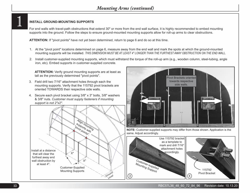
1 INSTALL GROUND-MOUNTING SUPPORTS
1. At the "pivot point" locations determined on page 6, measure away from the end wall and mark the spots at which the ground-mounted mounting supports will be installed. THIS DIMENSION MUST BE AT LEAST 4" LONGER THAN THE FURTHEST AWAY OBSTRUCTION ON THE END WALL.
2. Install customer-supplied mounting supports, which must withstand the torque of the roll-up arm (e.g., wooden column, steel-tubing, angle iron, etc). Embed supports in customer-supplied concrete. ATTENTION: Verify ground mounting supports are at least as tall as the previously determined "pivot points".
3. Field drill two 7/16" attachment holes through each the mounting supports. Verify that the 115792 pivot brackets are oriented TOWARDS their respective side walls.
4. Secure each pivot bracket using 3/8" x 3" bolts, 3/8" washers & 3/8" nuts. Customer must supply fasteners if mounting support is not 2"x2".
Customer-supplied
Mounting Support
Use 115792 bracket as a template to
mark and drill 7/16" attachment holes
accordingly.
NOTE: Customer-supplied supports may differ from those shown. Application is the same. Adjust accordingly.
Pivot Brackets oriented towards respective
side walls.
3 4
115792 Pivot Bracket
For end walls with travel-path obstructions that extend 30" or more from the end wall surface, it is highly recommended to embed mounting supports into the ground. Follow the steps to ensure ground-mounted mounting supports allow for roll-up arms to clear obstructions. ATTENTION: If "pivot points" have not yet been determined, return to page 6 and do so at this time.
Ground
Level
Customer-Supplied Mounting Supports
X"
X"
Install at a distance that will clear the furthest away end wall obstruction by
at least 4".
Align mounting
supports with
"pivot points".

11Revision date: 10.13.20 RBC57L36_48_60_72_84_96
NOTE: THE DOUBLE CHANNEL POLYLOCK IS PLACED UNDER THE GREENHOUSE FILM.
(2X) DOUBLE CHANNEL POLYLOCK [ ]
TRACK CONNECTOR [ ]- (4X) 3/8" X 1-1/2" HEX BOLT - (8X) 3/8" WASHER- (4X) 3/8" HEX NUT
The 104211 u-channel is the anchor point for the roll-up curtains. It is installed at the peak of the shelter. INSTALLATION SCENARIO #1: Roof cladding has not yet been installed. Install peak curtain channel BEFORE installing the roof cladding material of the shelter.
INSTALLATION SCENARIO #2: Roof cladding is installed, but can be removed. Remove roof cladding, install the peak curtain channel, and then re-install roof cladding.
INSTALL PEAK CURTAIN CHANNEL2
1. Along the peak of the shelter, attach 104211 curtain channel to the rafters using FA4477B Tek screws. Install a Tek screw in each channel at each rafter.
2. Splice 104211 as needed using 115573 brackets, 3/8" x 1-1/2" bolts, 3/8" nuts & 3/8" washers. See splice hardware orientation note above and to the right. Field drill all splice holes and trim excess channel as needed. IMPORTANT: For the 116291 and 116292 Low Pro High Tunnels and the 117046 and 117047 Premium High Tunnels, return to the building instruction manual and continue as instructed. For all other applications, continue with Step 3 that follows.
3. Install or re-install roof cladding.
4. Secure film cladding in both channels of peak curtain channel using 102198A spring wire.
5. Install jumper for air inflation system if needed.
Peak Curtain Channel
IMPORTANT: During installation, orient splice bolts so bolt-heads face roof cladding.
ATTENTION: Ignore diagrams showing installation of peak channel over roof cladding. Verify that peak channel is installed before any roof cladding.
Carefully trim excess.
104211 curtain channel installed at the peak
Attach to rafters using FA4477B
Tek screws.
Seal around screws for leak protection,
if desired.
Secure cladding using 102198A
spring wire.

12 RBC57L36_48_60_72_84_96 Revision date: 10.13.20
1. Position curtain material along the base of one side of the building.
2. Unfold curtain and verify that width and length are properly oriented with width and length of the building. Edge with keder rope will align with the side wall. ATTENTION: Measure curtain material and compare it to the over-the-top measurement of your building before installation! Consult the diagram in the technical documents for the over-the-top measurement. Curtain should be at least 1' longer than over-the-top measurement.
3. Along the keder edge, clamp self-locking, duck-billed pliers to the curtain material and tie customer-supplied ropes or straps to the pliers. NOTE: The ropes or straps must reach over the top of the building to the other side. The number of ropes depends on building length; use additional ropes spaced even throughout the length to prevent curtain damage when it is pulled into place.
4. After tying ropes to the curtain, throw ropes over the building and pull curtain into place. IMPORTANT: To prevent damage to the curtain during installation, use additional personnel and lifts as needed.
WARNING: To prevent damage to curtain and to prevent serious personal injury, DO NOT attempt to install curtain on windy or stormy days.
NOTE: Installation procedure may vary slightly depending on length of building and number of assistants; buildings longer than 48' typically require more than three (3) assistants even when conditions are ideal. Adjust these steps as needed to safely and properly install the curtain.
Clamp self-locking, duck-billed pliers along curtain edge, tie ropes or straps to the pliers, and then pull curtain over the frame.
PREPARE AND INSTALL ROLL-UP CURTAIN
IMPORTANT: Before installing roll-up curtain, verify roof cladding and end wall cladding have been installed. Only after these items have been installed should you continue with the curtain installation.
Blackout Roll-Up Curtain
3
IMPORTANT! Install curtain so that the WHITE side is to the outside.
NOTE: Actual shelter and curtain may differ. All applications are the same
Roll-up Curtain

13Revision date: 10.13.20 RBC57L36_48_60_72_84_96
5. Center curtain side-to-side and end-to-end. IMPORTANT: Verify that 12" of material hangs over each end.
6. Once curtain is in place and centered, pull curtain tight (end-to-end) and install the 102198A wire spring into the 104211 channel at the peak.
7. Trim excess springwire, secure curtain, and remove ropes. ATTENTION: There will be excess curtain along the sides at the bottom base on both sides. DO NOT TRIM. This excess is edged with keder rope which will be installed into the roll-up conduit and rolled up to the base in a later step.
WEAR EYE PROTECTION
WHEN INSTALLING
SPRING WIRE!
Photo above shows 102198A spring wire used to secure curtain material to the 104211 channel attached to the peak of the shelter. Arrows indicate location of keder rope in panel edge.
12" CurtainOverlap
3
NOTE: Actual shelter and curtain may differ. All applications are the same
Blackout Roll-Up Curtain (continued)

14 RBC57L36_48_60_72_84_96 Revision date: 10.13.20
Roll-up curtain conduit is an aluminum axle that includes a groove that accepts the keder rope present along the base edge of the curtain. After installing the curtain, the conduit is assembled and slid onto the keder curtain edge.
INSTALL ROLL-UP CURTAIN CONDUIT
Secure coupler to roll bar on each side using FA4472 Tek screws (8 per coupler).
Roll-Up Curtain Conduit
41. Using 113768Z024 splice couplers and FA4472B Tek screws, assemble a run of 108517 roll-up conduit for each side. Verify that the conduit is
long enough to extend to the motor on the operation end, and 1" past the edge of the opposite end. See diagrams below.
2. With assistance, slide the roll-up curtain conduits onto the keder rope edges of the roll-up curtain. ATTENTION: Keder edges of the curtain may be difficult to slide into keder channel of the conduit. If necessary, apply dish soap for ease of installation, or slide the 10' sections of conduit onto the keder individually before splicing.
3. Verify all Tek screws are covered with duct tape to protect the roll-up curtain.
Verify conduit extends to roll-up arm bracket.
Conduit AssemblyRoll-up Curtain
with keder rope edge
Verify conduit extends 1' past the end of shelter.
Keder Rope
Roll-up Curtain Conduit
Measure and mark midpoint on coupler. Align conduit splice ends with mark before securing.
1085
17Cu
rtain
Cond
uit
1137
68Z0
24
Condu
it Spli
ce
108517
Curtain Conduit
108517
Curtain Conduit

15Revision date: 10.13.20 RBC57L36_48_60_72_84_96
Due to the weight of the motor, the motor ends of the roll-up curtain conduit will tend to lag when rolling up. Gradually tapering the motor-end edges of the conduit will increase the roll diameter of the conduit so that the curtain will evenly roll-up.
TAPER CONDUIT4
2. Roll the conduit up to base along the sides of the shelter. Verify conduit is straight and uniform. Temporarily hold in place and continue by installing anti-billow strapping.
1. Using 116220 spacers, CC6214 fabric clips, and CC6216 fabric clips, gradually taper the the curtain conduit runs at the motor ends. ATTENTION: Exact configuration of the tapered edge may vary due to several factors (e.g. curtain installation, shelter length, shelter profile) so quantity of fabric clips may differ from what is shown. Adjustments may need to be made at any time, even after installation is complete. Adjust according to how uniformly the roll-up conduit travels when in operation.
Roll-Up Curtain Conduit (continued)
CC6216 (x2)CC6216 (x1)
Roll-up Curtain
Gradual tapering in diameter from the outside in.
CC6216 (x1)CC6214 (x2)
Uniformly roll-up excess curtain onto the curtain conduit up to the base of shelter.
CC6214 (x1)
Roll-up Curtain
116220Slotted Spacer
Curtain Conduit

16 RBC57L36_48_60_72_84_96 Revision date: 10.13.20
5 INSTALL ANTI-BILLOW STRAPPING
Anti-Billow Strapping
109621
Anti-Billo
w
Straps
QH1065 Strap Ratchets&
109329 Ratchet Brackets
Anti-billow strapping prevents curtains from blowing away from the building.
1. Along the shelter base, below the roll-up curtain conduit, evenly space, measure, and mark anti-billow strap locations. Locations are not critical, but it is important that the distance between strap locations not exceed 10', and that a strap is installed at each end. IMPORTANT: Strap locations on either side MUST be MIRRORED.
2. Using provided hardware, install QH1065 ratchets to the 109329 brackets.
3. At the locations marked in step 1, attach the ratchet bracket assembly to the foundation. Due to different foundation materials, hardware to attach brackets is customer supplied. ATTENTION: The 109329 brackets are not used for the 116291 and 116292 Low Pro High Tunnel buildings or the 117046 and 117047 Premium High Tunnels
4. At each ratchet location, run 109621 anti-billow strap over the shelter to the mirrored location on the other side.
5. Cut strap to fit at the recommended length of the over-the-top measurement plus an additional 4'.
6. Thread strap through the ratchets and lightly tighten. Loosen straps as needed to adjust roll-up conduit. WARNING: DO NOT OVER-TIGHTEN STRAPPING! Doing so may damage roll-up curtain or obstruct operation of the roll-up conduit.
109329 Ratchet Bracket
QH1065Ratchet
Ratchet Bracket
Carriage Bolt
Roll-up Conduit
Anti-billow Strap
Customer-Customer-Supplied Supplied FastenersFasteners

17Revision date: 10.13.20 RBC57L36_48_60_72_84_96
6 ASSEMBLE & INSTALL ROLL-UP ARMS
1. Locate two 131S123 swaged pipes and splice together as shown using provided two (2) 1/4" x 2" bolts, two (2) 1/4" nuts & four (4) 1/4" washers. Field drill splice holes.
2. At plain end of the assembled roll-up arm, measure 1" from end and drill a 1/2" hole through pipe.
3. On one side of the shelter, attach roll-up arm assembly to the 115792 pivot bracket attached to the mounting arm using one 3/8" x 3" bolt, six 3/8" spacer washers & one 3/8" lock-nut,. DO NOT OVER-TIGHTEN! Roll-up arm must pivot freely.
4. Test travel path of the roll-up arm from peak to ground to verify it will not interfere with any obstructions. Trim to length as needed, but verify that AT LEAST 12" of roll-up arm extends past the rafter at any given point along the travel path. Cap with WF2995 pipe cap.
5. Repeat to atach remaining roll-up arm.
Roll-Up Arms
Roll-up Arms
131S123
131S123
Plain end of assembled roll-up arm.
(1) 3/8" x 3" bolt(6) 3/8" spacer washers(1) 3/8" lock-nut
Measure 1" and mark through-hole location.
(2) 1/4" x 2" bolts(4) 1/4" washers(2) 1/4" nuts
Verify at least 12" of pipe extends past the rafter at any given point from ground to peak.
IMPORTANT: Verify that roll-up arm splice will not obstruct the motor roller assembly as it travels.

18 RBC57L36_48_60_72_84_96 Revision date: 10.13.20
7 ASSEMBLE ROLL-UP MOTOR ASSEMBLY
Motors
1. Using a 3/16" x 2-1/2" bolt, shear pin and a 3/16" nylon lock-nut, secure 109906D tube adapter to the motor as shown. Adapter connects the electric motor to the roll-up curtain conduit.
2. Secure motor to the 116019 roll-up motor bracket using metric bolts provided with motor as shown below. Do not overtighten the mounting bolts. Doing so may damage the motor housing.
3. Repeat steps for second roll-up motor assembly.
ATTENTION: Actual motor and adapter may differ. Application is the same. Adjust accordingly.
116018Roll-Up Motor
109906D Motor-to-Roll Bar Adapter
117107 & 117095Adaptor Bolt & Lock-Nut
Secure to bracket attachment holes using provided metric bolts.
Attachment HolesAttachment Holes
116019Roll-Up Motor Bracket
117058 Shear Pin

19Revision date: 10.13.20 RBC57L36_48_60_72_84_96
7Motors (continued)
4. Slide a roll-up motor assembly onto each roll-up arm.
5. Insert each motor adapter into the open end of the roll-up conduit. Trim conduit to length, if necessary.
6. With the adapters firmly set into the roll-up conduit ends, field drill two 5/16" splice holes.
7. Using 1/4" x 2" bolts and 1/4" lock-nuts, secure the motor adapters to the roll-up conduits.
8. Once conduits and motors are in place as desired, retighten any loosened anti-billow straps for cover protection.
Roll-up Conduit

20 RBC57L36_48_60_72_84_96 Revision date: 10.13.20
7Motors (continued)
1. With all blackout system components fully installed, it will be imperitive to test the operation to verify funcionality. If not already done so, CONTACT A LICENSED ELECTRICIAN FOR ALL MOTOR WIRING DETAILS. Consult manuals sent with motor and controller for set-up.
2. Operate the motor to open and close two or three times to test the operation. Testing system will exercise the material to allow for a consistent stopping point for the motor. IMPORTANT: Curtains will not FULLY open to the peak. It is important to stop the curtain AT LEAST 1-1/2" from the peak.
3. When satisfied with open and closed position of motors, curtains, and curtain conduits, set the limits of the motor. Consult the paperwork included with the motor for limit-setting procedures.
4. Once upper and lower limits are set, run the curtain components a minimum of five times to ensure limits are at the desired setting while the fabric settles. Tighten the lock screws on the limit switch knobs.
OPERATION TESTING
1. After all operation details have been tested, verify all areas are sealed tight and that light does not leak into system. The following components are inlcuded to help seal trouble areas like corners, and along sealing edges: -115198, black-out tape -DE4009, polycarbonate sealing caulk ATTENTION: Many minor details and touch-ups are taken care of at the customer's discretion. A great deal of carefulness, craftsmanship, and throroughness is required, and proper installation will eliminate potential issues.
2. Additional light deprivation at light-leaking trouble areas are customer-supplied.
LIGHT DEPRIVATION

21Revision date: 10.13.20 RBC57L36_48_60_72_84_96
Quick Start Guide
CENTER TO CENTER OF GROUND POSTS
CENTER OF STRUCTURE TO
CENTER OF ENDWALL COLUMN
CE
NTE
R O
F 10
4624
TO
BO
TTO
M O
F B
AS
E P
LATE
SYMMETRICAL
OR
ROLLUP MOTOR
[ ]
[ ] BATTEN TAPE(OVER-THE-TOP)APPROX. EVERY 10'-0" AND AT EACH END
CL
QUICK START GUIDE
Over-The-Top Blackout System
FRONT PROFILE

22 RBC57L36_48_60_72_84_96 Revision date: 10.13.20
Connections
MOTOR TO ROLL BAR ATTACHMENT
ROLL BAR SPLICE
DOUBLE CHANNEL POLYLOCK SPLICE DETAIL
ROLL-UP ARM ATTACHMENT
TYPICAL DOUBLE CHANNEL POLYLOCK DETAIL
ROLL-UP ARM SPLICE

23Revision date: 10.13.20 RBC57L36_48_60_72_84_96
ROLL BAR [ ]- (1X) 1/4" X 2" HEX BOLT- (1X) 1/4" HEX NUT
ROLL BAR [ ]
ROLL BAR [ ]
ROLL BAR COUPLER [ ]
- (8X) #12 X 1" TEK SCREW
BRACKET [ ]- (2X) 3/8" X 3" HEX BOLT (THRU )- (1X) 3/8" X 3" HEX BOLT (THRU )- (6X) 3/8" WASHER- (3X) 3/8" HEX NUT
INSERT [ ]- (2X) 3/8" X 3" HEX BOLT (THRU POLYCARBONATE AND ENDWALL HEADER)- (1X) 3/8" X 3" HEX BOLT (THRU )- (6X) 3/8" WASHER- (3X) 3/8" HEX NUT
MOTOR TO ROLL BAR ATTACHMENT
NOTE: THE DOUBLE CHANNEL POLYLOCK IS PLACED UNDER THE GREENHOUSE FILM.
NOTE: THE 2" X 2" PIPE COULD ALSO BE PLACED ON THE GROUND PARALLEL WITH THE ENDWALL, IF THE BUILDING IS NOT PLACED ON A WALL.
DOUBLE CHANNEL POLYLOCK [ ]
POLYLOCK SPRING [ ]
BLACKOUT MATERIAL
BLACKOUT MATERIAL
DOUBLE CHANNEL POLYLOCK [ ]
POLYLOCK SPRING [ ]
DOUBLE CHANNEL POLYLOCK SPLICE DETAIL
131S123
131S123
- (2X) 1/4" X 2" HEX BOLT - (2X) 1/4" LOCKNUT
ROLL- UP ARM SPLICE
ROLL BAR SPLICE ROLL-UP ARM ATTACHMENT
TYPICAL DOUBLE CHANNEL POLYLOCK DETAIL
NOTE: TOTAL LENGTH OF ROLL-UP BAR IS 4'-0" MORE THAN OVERALL LENGTH OF THE STRUCTURE.
(2X) DOUBLE CHANNEL POLYLOCK [ ]
TRACK CONNECTOR [ ]- (4X) 3/8" X 1-1/2" HEX BOLT - (8X) 3/8" WASHER- (4X) 3/8" HEX NUT
Connection Details


![Top Down Assembly Modeling[1]](https://img.pdfslide.net/doc/110x75/577d29e21a28ab4e1ea82487/top-down-assembly-modeling1.jpg)