Embed Size (px)
Citation preview
ASSEMBLY, INSTALLATION, AND REMOVAL OF CONTACTS AND MODULESFOR PNEUMATIC CONTACTS AND MODULES
Table of Contents
SECTION 1 CONTACT INSTALLATION AND REMOVAL INSTRUCTIONS
SECTION 2 MODULE INSTALLATION AND REMOVAL INSTRUCTIONS
SECTION 3 CROSS REFERENCE TABLES
SECTION 4 PRODUCT PERFORMANCE SPECIFICATIONS
5/6/16
Please note that any printed or downloaded User Manuals or Procedure Sheets may not reflect the most current revisions. The information contained in these materials is subject to change.
For the most current information available, visit www.vpc.com.
PNEUMATIC CONTACTS AND MODULES USER’S MANUAL: SECTION 1 VIRGINIA PANEL CORPORATION
1-1 5/6/16For the most current information available, visit www.vpc.com
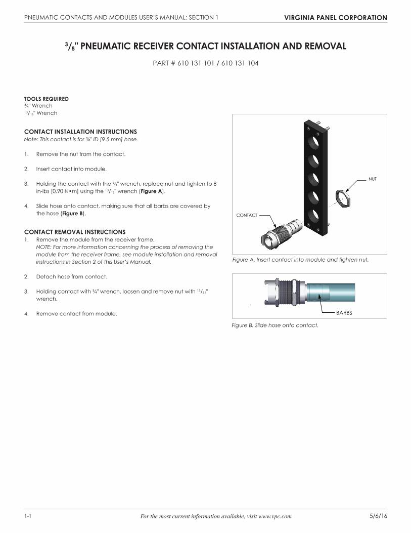
3/8" PNEUMATIC RECEIVER CONTACT INSTALLATION AND REMOVALPART # 610 131 101 / 610 131 104
Figure B. Slide hose onto contact.
Figure A. Insert contact into module and tighten nut.
TOOLS REQUIRED¾" Wrench13/16" Wrench
CONTACT INSTALLATION INSTRUCTIONS Note: This contact is for ⅜" ID [9.5 mm] hose.
1. Remove the nut from the contact.
2. Insert contact into module.
3. Holding the contact with the ¾" wrench, replace nut and tighten to 8 in-lbs [0.90 N•m] using the 13/16" wrench (Figure A).
4. Slide hose onto contact, making sure that all barbs are covered by
the hose (Figure B).
CONTACT REMOVAL INSTRUCTIONS1. Remove the module from the receiver frame. NOTE: For more information concerning the process of removing the
module from the receiver frame, see module installation and removal instructions in Section 2 of this User’s Manual.
2. Detach hose from contact.
3. Holding contact with ¾" wrench, loosen and remove nut with 13/16" wrench.
4. Remove contact from module. BARBS
CONTACT
NUT

PNEUMATIC CONTACTS AND MODULES USER’S MANUAL: SECTION 1 VIRGINIA PANEL CORPORATION
1-2 5/6/16For the most current information available, visit www.vpc.com
CONTACT INSTALLATION INSTRUCTIONS Note: This contact is for ⅛" ID [3.2 mm] hose.
1. Press contact into module until it snaps in place (Figure A).
2. Slide hose onto contact, making sure that all barbs are covered by the hose (Figure B).
CONTACT REMOVAL INSTRUCTIONS1. Remove module from the ITA frame. NOTE: For more information concerning the process of removing
the module from the receiver frame, see module installation and removal instructions in Section 2 of this User’s Manual.
2. Detach hose from contact.
3. Press contact out of the other side of the module (Figure C). NOTE: Some force will be required to remove contact from module.
1/8" PNEUMATIC ITA CONTACT INSTALLATION AND REMOVALPART # 610 131 106
BARBS
Figure C. Press contact out of module.
Figure A. Press contact into module.
Figure B. Slide hose onto contact.
PNEUMATIC CONTACTS AND MODULES USER’S MANUAL: SECTION 1 VIRGINIA PANEL CORPORATION
1-3 5/6/16For the most current information available, visit www.vpc.com
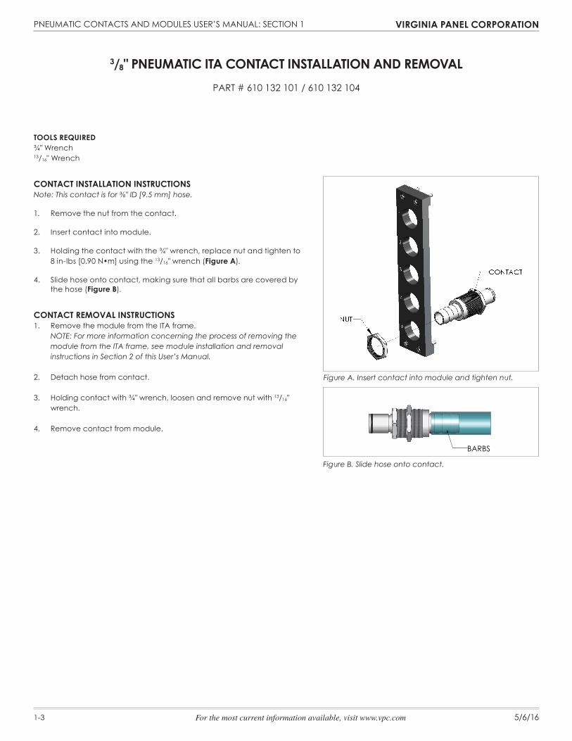
3/8" PNEUMATIC ITA CONTACT INSTALLATION AND REMOVALPART # 610 132 101 / 610 132 104
Figure A. Insert contact into module and tighten nut.
Figure B. Slide hose onto contact.
BARBS
TOOLS REQUIRED¾" Wrench13/16" Wrench
CONTACT INSTALLATION INSTRUCTIONSNote: This contact is for ⅜" ID [9.5 mm] hose.
1. Remove the nut from the contact.
2. Insert contact into module.
3. Holding the contact with the ¾" wrench, replace nut and tighten to 8 in-lbs [0.90 N•m] using the 13/16" wrench (Figure A).
4. Slide hose onto contact, making sure that all barbs are covered by
the hose (Figure B).
CONTACT REMOVAL INSTRUCTIONS1. Remove the module from the ITA frame. NOTE: For more information concerning the process of removing the
module from the ITA frame, see module installation and removal instructions in Section 2 of this User’s Manual.
2. Detach hose from contact.
3. Holding contact with ¾" wrench, loosen and remove nut with 13/16" wrench.
4. Remove contact from module.

PNEUMATIC CONTACTS AND MODULES USER’S MANUAL: SECTION 1 VIRGINIA PANEL CORPORATION
1-4 5/6/16For the most current information available, visit www.vpc.com
CONTACT INSTALLATION INSTRUCTIONS Note: This contact is for ⅛" ID [3.2 mm] hose.
1. Press contact into module until it snaps in place (Figure A).
2. Slide hose onto contact, making sure that all barbs are covered by the hose (Figure B).
CONTACT REMOVAL INSTRUCTIONS1. Remove module from the receiver frame. NOTE: For more information concerning the process of removing
the module from the frame, see module installation and removal instructions in Section 2 of this User’s Manual.
2. Detach hose from contact.
2. Press contact out of the other side of the module (Figure C). NOTE: Some force will be required to remove contact from
module.
NOTE: Can be used in either a receiver or ITA module, but must be mated with Part # 610 131 106 in the remaining module.
1/8" PNEUMATIC RECEIVER CONTACT INSTALLATION AND REMOVALPART # 610 132 105 / 610 131 107
BARBS
Figure C. Press contact out of module.
Figure A. Press contact into module.
Figure B. Slide hose onto contact.
PNEUMATIC CONTACTS AND MODULES USER’S MANUAL: SECTION 2 VIRGINIA PANEL CORPORATION
2-1 5/6/16For the most current information available, visit www.vpc.com
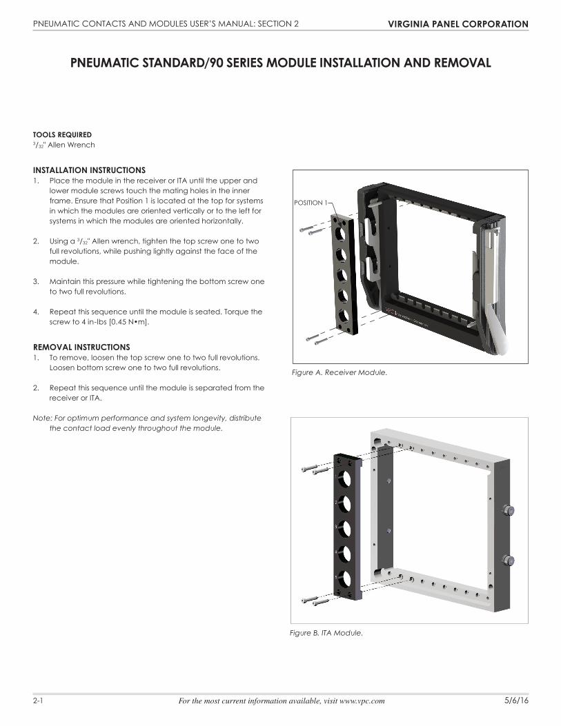
PNEUMATIC STANDARD/90 SERIES MODULE INSTALLATION AND REMOVAL
Figure A. Receiver Module.
Figure B. ITA Module.
TOOLS REQUIRED3/32" Allen Wrench
INSTALLATION INSTRUCTIONS1. Place the module in the receiver or ITA until the upper and
lower module screws touch the mating holes in the inner frame. Ensure that Position 1 is located at the top for systems in which the modules are oriented vertically or to the left for systems in which the modules are oriented horizontally.
2. Using a 3/32" Allen wrench, tighten the top screw one to two full revolutions, while pushing lightly against the face of the module.
3. Maintain this pressure while tightening the bottom screw one to two full revolutions.
4. Repeat this sequence until the module is seated. Torque the screw to 4 in-lbs [0.45 N•m].
REMOVAL INSTRUCTIONS1. To remove, loosen the top screw one to two full revolutions.
Loosen bottom screw one to two full revolutions.
2. Repeat this sequence until the module is separated from the receiver or ITA.
Note: For optimum performance and system longevity, distribute the contact load evenly throughout the module.
POSITION 1
PNEUMATIC CONTACTS AND MODULES USER’S MANUAL: SECTION 3 VIRGINIA PANEL CORPORATION
3-1 5/6/16For the most current information available, visit www.vpc.com
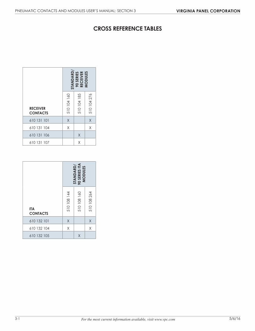
RECEIVER CONTACTS
STAN
DARD
/ 90
SER
IES
REC
EIVE
R M
ODU
LES
510
104
160
510
104
185
510
104
276
610 131 101 X X
610 131 104 X X
610 131 106 X
610 131 107 X
ITA CONTACTS
STAN
DARD
/ 90
SER
IES
ITA
MO
DULE
S
510
108
144
510
108
160
510
108
264
610 132 101 X X
610 132 104 X X
610 132 105 X
CROSS REFERENCE TABLES
PNEUMATIC CONTACTS AND MODULES USER’S MANUAL: SECTION 4 VIRGINIA PANEL CORPORATION
4-1 5/6/16For the most current information available, visit www.vpc.com
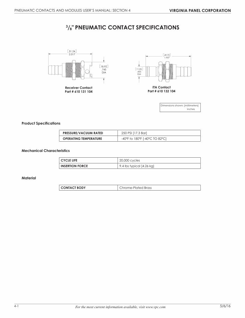
3/8" PNEUMATIC CONTACT SPECIFICATIONS
Receiver ContactPart # 610 131 104
Product Specifications
PRESSURE/VACUUM RATED 250 PSI [17.3 Bar]
OPERATING TEMPERATURE -40ºF to 180ºF [-40ºC TO 82ºC]
Mechanical Characteristics
CYCLE LIFE 20,000 cycles
INSERTION FORCE 9.4 lbs typical [4.26 kg]
Material
CONTACT BODY Chrome-Plated Brass
ITA ContactPart # 610 132 104
18.92
DIA.745
2.01751.24
11.05
DIA.435
1.95749.72
Dimensions shown: [millimeters] inches

PNEUMATIC CONTACTS AND MODULES USER’S MANUAL: SECTION 4 VIRGINIA PANEL CORPORATION
4-2 5/6/16For the most current information available, visit www.vpc.com
1/8" PNEUMATIC CONTACT SPECIFICATIONS
Receiver ContactPart # 610 131 106
Product Specifications
PRESSURE/VACUUM RATED 100 PSI [6.9 Bar]
OPERATING TEMPERATURE -40ºF to 180ºF [-40ºC TO 82ºC]
Mechanical Characteristics
CYCLE LIFE 20,000 cycles
INSERTION FORCE 1.5 lbs typical [0.68 kg]
Material
CONTACT BODY Delrin®
ITA ContactPart # 610 132 105
DIA
8.315
.89222.66
8
DIA.315
.89222.66
Dimensions shown: [millimeters] inches