Embed Size (px)
Citation preview

Ass
embly
Inst
ruct
ion
PSU 8-16 R

-2- PSU8-16R
Contents
1 Notesaboutsafetyandhazards..................................................................4
2 Generalinformation....................................................................................62.1 Meaning of the symbols used ..........................................................62.2 Scope of delivery ..........................................................................62.3 Available accessories .....................................................................62.4 Technical data ...............................................................................72.5 Description ...................................................................................8
3 Overview....................................................................................................93.1 Front cover ...................................................................................93.2 Connectors and components ...........................................................9 Front view / side view (type label) ......................................................9 View from below .........................................................................10 Rear view ...................................................................................103.3 Control unit .................................................................................11 Power supply units .......................................................................11
4 Installingthehead-endstation...................................................................124.1 Remove front cover ......................................................................124.2 Mounting the head-end station ......................................................12 Wall mounting ............................................................................13 Mounting in a 19" cabinet ...........................................................14
5 Installingacassette...................................................................................15
6 Connectingthehead-endstation................................................................167.1 Potential equalisation (PE) .............................................................166.2 EMC regulations (electromagnetic compatibility) ..............................166.3 Connecting RF output of the head-end station ..................................176.4 Power supplies/Mains connection .................................................17 Operating status indicators, alarm tone ..........................................18 Replacing a power supply ............................................................18 Internal power supplies ................................................................19
LNB power supply ..................................................................19 Connecting peripheral devices .................................................19
7 Settingthecontrastofthedisplay...............................................................20
8 Thecontrolpanelataglance.....................................................................218.1 Control panel ..............................................................................218.2 Menu items .................................................................................21

-3- PSU8-16R
9 Updatingthesoftwareofthecontrolunit....................................................229.1 Updating software via PC .............................................................229.2 Updating the software via second control unit .................................22 Removing master control unit .........................................................22 Programming slave control unit ......................................................23 Inserting master control unit ..........................................................24
11Programming............................................................................................2411.1 Preparation .................................................................................2410.2 Programming procedure ...............................................................25 Message after temperature exceeding ............................................2610.3 Programming the head-end station ................................................27 Activating system information ........................................................28 System information – control unit ...................................................28
Perform settings ......................................................................28 Call up information about the head-end station ..........................28
System information – output collector .............................................29 System information – temperature ..................................................29 System information – number of the head-end station .......................30 System information – clock frequency .............................................30 Setting the RF output level of the cassettes ......................................30 Setting the RF output level of the head-end station ............................31 Setting the consecutive number of the head-end station .....................31 Activating the modem connection ..................................................32 Setting the password ....................................................................32 Saving settings ............................................................................33 Programming the head-end station (following excess temperature) .....33 System information ......................................................................3410.4 Programming via the control software ............................................35 Redundant Power Supply .........................................................35
Restart the cassettes of a station (reset) ......................................36 Station configuration ..............................................................37
11Finalprocedures........................................................................................38

-4- PSU8-16R
1 notesaboutsafetyandhazards
• The head-end station is subject to the regulations of protection class I. • Never operate the device without a protective earth connection, earth con-
nection to the device and potential equalisation! • Observe the relevant VDE regulations. • Ifthepowercordneedstobereplaced,onlyuseanOEMpowercord(EMC). • The standards EN/DIN EN 50083 resp. IEC/EN/DIN EN 60728 must be
observed, especially concerning equipotential bonding and earthing. • Observe the relevant standards, regulations and guidelines on the installa-
tion and operation of antenna systems. • Before starting installation or service work disconnect the receiving system
from mains. For a complete disconnection from the mains, the mains plug must be pulled out of the mains socket. Ensure that the mains plug can be pulled out without difficulties.
• Do not perform installation and service work during thunderstorms. • Assembly, installation and servicing must be carried out by an authorised
electrician. • Thehead-endstationshouldonlybeinstalledinaroomwherethepermissi-
bleambienttemperaturerange(0°Cand+50°C)canbemaintained,evenduringfluctuationsinclimaticconditions.
• Makesurethereisaminimumspace - atwallmounting50cmaboveandbelow - atmountingina19"cabinet20cmaboveandbelow,aswellas10cm
behind. • Toavoid too strongheatingof thehead-end stations it is notadmissible
tomountthemoneupontheotherwithoutusingthermicprecautions(e.g.permanentlyairrecirculation,ventilation,heatdeflectorsetc.).
• If additional fans are to be used to circulate the air, ensure that the system will be shut down (disconnected from mains) should any one of the fans fail.
• Install the head-end station - in a dry, dust-free environment - in such a manner that it is protected from moisture, fumes, splashing wa-
ter and dampness - where it is protected from direct exposure to sunlight - on a vibration-free wall or floor construction - not within the immediate vicinity of heat sources • In case of the formation of condensation wait until the system is completely
dried. • Ensure that the head-end station is adequately ventilated.

-5- PSU8-16R
• Do not cover the ventilation openings! • Do not install the head end in cabinets or recesses which are not ventilated. • Do not place any vessels containing liquids on the head-end station. • Do not place anything on the head-end station which could initiate fires
(e.g. candles). • Due to the risk of fires caused by lightning strikes, we recommend that all
mechanical parts (e.g. distributor, equipotential bonding rail, etc.) be mounted on a non-combustible base. Wood panelling, wooden beams, plastic covered panels and plastic panels are all examples of combustible bases.
• Avoid short circuits! • To ensure electromagnetic compatibility, make sure all connections are tight
and that the covers are screwed on securely. • No liability is accepted for damage caused by faulty connections or inap-
propriate handling of the device. • You can obtain additional information from the "Planungshandbuch" bro-
chure (only in German) which can be found on the website "http://www.mygss.eu" under the "Miscellaneous" category.
Electronicdevicesshouldneverbedisposedof in thehousehold rubbish. Inaccordancewithdirective2002/96/ECof theEuropeanParliamentand theEuropeanCouncilfromJanuary27,2003whichaddressesoldelectronicandelectricaldevices,suchdevicesmustbedisposedofatadesignatedcollectionfacility.Attheendofitsservicelife,pleasetakeyourdevicetooneofthesepubliccollectionfacilitiesforproperdisposal.

-6- PSU8-16R
2 Generalinformation
2.1 meaninGofthesymbolsused
Important note
• Performing works
Danger by electrical shock
—> General note
2.2 sCopeofdel ivery
1 PSU 8-16 R head-end station (without cassettes) 1 DVD (assembly instructions) 1 Brief assembly instructions 2 Power cords
2.3 availableaCCessories
For cassettes and accessories see website "www.mygss.eu".

-7- PSU8-16R
2.4 teChniCaldata
The devices meet the following EU directives: 2011/65/EU, 2014/30/EU, 2014/35/EU The product fulfils the guidelines and standards for CE labelling (page 39).
Unless otherwise noted all values are specified as "typical".
GeneralCassette slots: .....................................................................................8Admissible ambient temperature: .........................................0°C…+50°C Dimensions (W x H x D) [mm]: ...................................... 483 x 410 x 302Mounting dimensions (W x H x D) [mm]: ...... 483 x 620 (14 HE/HU) x 302
incl. free space to replace the power supplyWeight (fully equipped): ..................................................... approx. 20 kgLNB operating voltage: ................ +12 V / ≤1 A total (short-circuit-proof)Other operating voltage: ............ +12 V / ≤1 A total (not short-circuit-proof,
use with appropriate external fuse only)RS 232 socket: ... data interface for software update and remote maintenance
RFoutputcollectorFrequency range: ........................................................... 45 … 860 MHzControl range of each input: .............................0 … –25 dB (electronically)Control range of each output: .............................0 … –6 dB (electronically)Input, output impedance: ................................................................. 75 Ω Return loss: ...................................................................................14 dBRF output: .................................................................................. F socketDecoupling loss of the inputs: ..........................................................30 dBInsertion loss (due to internal amplifier): ..............................................0 dBOutput level with 16 channels .......................................maximum 93 dBµV
PowersupplyMains voltage: .................................................... 220–240V~, 50/60 HzPower supplies (individually hot swappable): ...........................................2Power consumption (fully equipped, incl. LNB power supply): .......... 210 W

-8- PSU8-16R
2.5 desCription
The head-end station has a modular structure and can hold up to 8 Profi cassettes. You can find a list of the current Profi cassettes at the website "www.mygss.eu". This head-end station is designed exclusively for use with cassettes of the Profi marketing programme. The various expansion options for the head-end station allow for the installation of a wide range of broadband cable systems.
The redundant power supply consisting of 2 complete power supplies in half-load operation, enables e.g. a UPS and mains operation or a 2-phase opera-tion. Both power supplies are individually hot swappable. In case of failure of a power supply, a warning tone sounds. One LED per power supply lights green during fault-free operation and red when the output voltage is faulty or overheating / a fan failure is present. The head-end station is designed to sup-ply power to components (e.g. LNBs) connected upstream. The head-end sta-tion’s power supply unit can be used to supply peripheral devices with voltage (+12 V / max. 1 A , with an external fuse).
By retrofitting two input distributors, 2x2 SAT IF inputs can be distributed to 2 x (4 + 6) outputs.
The cassettes’ RF output signals are accumulated in a programmable RF output collector and then directed to the RF output. When the head-end station is shipped from the factory, the default setting for the RF output level of the output collector is -3 dB. You can use the software of the control unit to program the master output level of the head-end station.
The software version of the control unit appears on the two-line LC display after switching on the head-end station. The display also supports dialogue guid-ance when programming the head-end station. Use the buttons of the control unit to programme the head-end station. You can also use the PSW 1000 soft-ware and the PRCU 8 / RCU 1 / PRCU 12 management unit to programme the head-end station.
The RS 232 interface of the control unit enables you to use a PC or a note-book and the "BE-Flash" software to update the operating software of the control unit. You can find the current operating software for the control unit, the software "BE-Flash" and the current assembly instructions on the website "www.mygss.eu".
If the inner temperature of the head-end station exceeds the permissible tem-perature of 65 °C when operating, a message appears in the display instead of the standby menu. This message contains the maximum measured tempera-ture and the number of the head-end station.

-9- PSU8-16R
3 overview
3.1 frontCover
Fig. 1
2 21
1 Locking screws 2 Mounting screws
—> TomaintaincompliancewiththeEMCregulations,thehead-endsta-tionmustnotbeoperatedwithoutthisfrontcover.
3.2 ConneCtorsandComponents
frontview/sideview(typelabel)
Fig. 2 22
!
452 2
3
6
K
7
W
2 Mounting screws for front cover 3 Cassette slots 1 … 8 4…6 Cover for cable terminals
—> TomaintaincompliancewiththeEMCregulations,thehead-endsta-tionmustnotbeoperatedwithoutthiscover.

-10- PSU8-16R
—> The rectangular openings are affected to mount RJ45 cable termi-nals.
4 Openings for SAT IF input distributor 5 Openings for SAT IF input distributor or LAN terminals 6 Openings for cable terminals 7 Control unit W Connector for peripheral devices (+12 V / max. 1 A ) K Type label
viewfrombelow
Fig.3
0
8
9
8 RF output of the head-end station 9 Distributor for LNB operating voltage 0 Potential equalisation screw
rearview
Fig.4
!
@ @
! Opening for the securing screw @ Openings for mounting screws (wall mounting)

-11- PSU8-16R
3.3 Controlunit
Fig.5
^
#
$
%
&
# LC display $ Control to set the contrast of the LC display. % 9-pin D-SUB socket to update the operating software, to connect the
PRCU 8 / RCU 1 / PRCU 12 management unit. ^ Control buttons (control panel) & Standby voltage indicator
powersupplyunits
Fig.6
*
™
(
)
¡
*
™
(
¡
)
* Socket for mains cable ( Reset button ) On/off switch ¡ Operating voltage indicator (LED) ™ Locking screw

-12- PSU8-16R
4 installinGthehead-endstation
4.1 removefrontCover
Fig.7
2 21
• Unscrew the locking screws 1. • Loosen the mounting screws 2. • Slide the front cover upwards and unhook it.
4.2 mountinGthehead-endstation
– Install the head-end station vibration-free. Avoid, for example, mounting the head-end station onto a lift shaft or any
other wall or floor construction that vibrates in a similar way. – Toavoid too strongheatingof thehead-end stations it is notadmissible
tomountthemoneupontheotherwithoutusingthermicprecautions(e.g.permanentlyairrecirculation,ventilation,heatdeflectorsetc.).
– Ensure that - the mounting area can support the weight of the head-end station - there is an adequate ventilation - the permissible ambient temperature will be maintained - the mounting position is dry and protected against splashing water.
—> For a complete disconnection from the mains, the mains plug must be pulled out of the mains socket. Ensure that the mains plug can be pulled out without difficulties.

-13- PSU8-16R
wallmountinG
—> Use mounting material suitable for the wallproperties.—> Position the head-end station so that the distance of free space be-
low and above is minimum50cm.—> The distance of the upper holes is 413 mm.
Fig.8 413 mm
30 mm30 mm
!
• Screw in the upper mounting screws at the position whished, mount the head-end station and mark the position for the locking screw !.
• Remove the head-end station and attach the hole for the locking screw. • Mount the head-end station and fix it with the locking screw !.
-14- PSU8-16R
mountinGina19"Cabinet
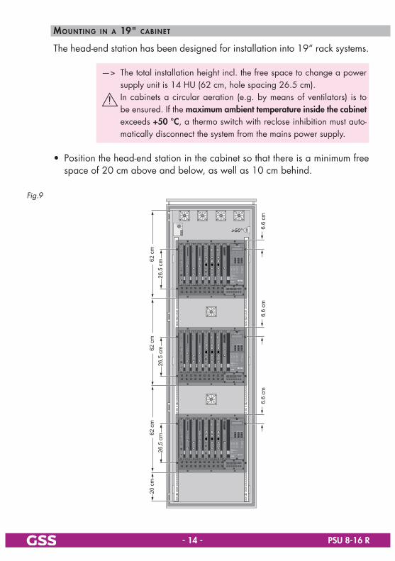
The head-end station has been designed for installation into 19“ rack systems.
—> The total installation height incl. the free space to change a power supply unit is 14 HU (62 cm, hole spacing 26.5 cm).
In cabinets a circular aeration (e.g. by means of ventilators) is to be ensured. If the maximumambienttemperatureinsidethecabinet exceeds +50°C, a thermo switch with reclose inhibition must auto-matically disconnect the system from the mains power supply.
• Position the head-end station in the cabinet so that there is a minimum free space of 20 cm above and below, as well as 10 cm behind.
Fig.9
>50 °25°15°
35°
20°
30°
20 c
m26
,5 c
m26
,5 c
m26
,5 c
m
6.6
cm6.
6 cm
6.6
cm
62 c
m62
cm
62 c
m

-15- PSU8-16R
5 install inGaCassette
Before installing or changing a cassette unplug the power cable of the head-end station from the mains power socket.
Fig.10
S
S
3
• Remove the fastening screws S of an unoccupied slot 3 from the bracket of the head-end station.
• Insert the cassette in this slot and push it into the housing. • Align the cassette according to the connections in the board and the RF col-
lector and press it firmly into place in the head-end station. • Fasten the cassette with the screws S.

-16- PSU8-16R
6 ConneCtinGthehead-endstation
7.1 potentialequalisation(pe)
Equalisethepotential(PE)inaccordancewithIEC/EN/DINEN60728.
Fig.11 GH
Gehäuse
• Put the PE wire (Cu 4 mm2 - 20 mm2) into the hole G of the PE connection ter-minal 0 (fig. 13, page 17) and fasten the PE wire with the screw H securely.
• Connect the PE connection terminal to a PE rail (supplied by customer) using the PE wire.
6.2 emCreGulations(electromagnetic Compatib i l ity)
TocomplywiththecurrentEMCregulations,itisnecessarytoconnectthelinesleadinginandoutofthehead-endstation(e.g.Cinch,RF)usingstandardca-bleterminals.
Fig.12
• According to figure 8 insert the required number of standard cable terminals in the openings provided in the front of the head-end station (fig. 2 4…6, page 9).
Tightenthenutsonthecableterminalsuntiltheteethonthelockwashershavepenetratedtheexteriorcoatingandagoodconnectionismadebetweenthehousingandthecableterminals.
—> TomaintaincompliancewiththeEMCregulations,thehead-endsta-tionmustnotbeoperatedwithoutthefrontcover.

-17- PSU8-16R
6.3 ConneCtinGrfoutputofthehead-endstation
Fig.13
0
8
9
• Connect the RF output of the hybrid amplifier 8 to the cable system.
6.4 powersuppl ies/mainsConneCtion
Useonlythemainscablessupplied.Theyarepartoftheapprovalandmustonlybereplacedbyanoriginalsparepart.
Fig.14
*
™
(
)
¡
*
™
(
¡
)
• Connect both power supplies * via the attached power cords to mains sockets.
—> By the two standby power supplies the control unit is supplied with voltage.
For a complete disconnection from the mains, the mains plug* must bepulledout.

-18- PSU8-16R
• Switch on the two power supply units by the on/off switches ).
—> At an error free operation the two operating status indicators ¡ will light green.
operatinGstatusindiCators,alarmtone
LED¡ State
green error free operation
red – voltage faulty– overtemperature– defect/blocked fan
off – switched off– no function/defective
If one power supply is defective or switched off, an alarm tone sounds until the reset button ( is pressed (Fig. 14, page 17).
In addition, the following message is displayed:
POWER SUPPLY
POWER WARNING ! !
! ! !
If both power supplies are defective or switched off, the following message is displayed:
POWER SUPPLY
POWER DOWN ! ! ! ! !
! ! !
—> The alarm tone and the fault indicators can only be emitted as long as the standby voltage is present.
replaCinGapowersupply
A power supply can be replaced during operation (hot swop). • Remove the mains cable * (Fig. 14, page 17). • Remove the locking screw ™ (Fig. 14, page 17). • Take the handle and pull the power supply upwards out of the housing.

-19- PSU8-16R
internalpowersuppl ies
lnbpowersupply
The LNB power supply (+ 12 V / max. 1 A ) is done via the connectors Y of the power distributor (Fig. 15).
The total output current for all LNBs connected must not exceed 1 A.
Fig.15
Y
ConneCtinGperipheraldeviCes
Via connector W (Fig. 2, page 9) peripheral devices can be supplied with power (+12 V / max. 1 A ).
Connectperipheraldevicesexclusivelyviaexternalfuses!

-20- PSU8-16R
7 settinGtheContrastofthedisplay
• Adjust the contrast of the display using the controller $.
^
#
$
%
&

-21- PSU8-16R
8 theControlpanelataGlanCe
8.1 Controlpanel
Program the head-end station using the buttons (control panel) on the control unit.
MODE scrolls forward through the menus. AUDIO scrolls backward through the menus. </> select parameters/submenus. +/– set values and trigger actions. MULTI selects presets. M saves all entries.
8.2 menuitems
The key pad on the head-end station is used to scroll through the menus. The two-line display of the control unit then shows the menus. The parameters and functions to be set are underlined. Use the key to select the following main menu items:
– System information – Output level of the cassettes – Output level of the head-end station – Number of the head-end station – Modem – Password

-22- PSU8-16R
9 updatinGthesoftwareoftheControlunit
9.1 updatinGsoftwareviapC
The RS 232 interface of the control unit enables you to use a PC or a notebook and the "BE-Flash" software to update the operating software of the control unit.
You can find the "BE-Flash" software and the current operating software of the head-end station’s control unit at the website "www.mygss.eu".
• Use a "one-to-one cable" to connect the control unit’s RS 232 interface and the PC.
9-pinD-SUB socket
9-pinD-SUB plug
123456789
123456789
—> For PCs with USB connector (without serial interface), we recom-mend the DeLOCK "USB 2.0 to Serial adapter" (Product No. 61460).
• Start the "BE-Flash" software and update the software of the control unit.
9.2 updatinGthesoftwareviaseCondControlunit
In this type of update, the current version of the software in one control unit (master) is transferred to the control unit you want to update (slave).
removinGmasterControlunit
£
≤
7
1
2
• Switch off the head-end station. • Disconnect snap-in hook £ in the direction of arrow " 1 ". • Pull control unit 7 in the direction of arrow " 2 " on the bottom and disconnect from snap-in hook ≤.

-23- PSU8-16R
proGramminGslaveControlunit
• Switch off the head-end station of the slave control unit. • Connect the 15-pin D-SUB plug on the back of the master control unit to the
RS 232 interface of the head-end station’s slave control unit via a connec-tion cable made on-site as follows.
9-pin D-SUB plug(Slave)
15-pin D-SUB socket(Master)
123456789
123456789
101112131415
1 kΩ
• Switch on the head-end station. • Wait for the "UpdateMode" message of the master control unit and press
button on this unit.
—> The software of the slave control unit is replaced by the master con-trol unit’s software.
• After the message "UpdateMode OK" appears, switch off the head-end station.
• Remove the connection cable between the slave and master control units. • Switch on the head-end station.
—> The head-end station’s slave control unit registers with the current version of the software.

-24- PSU8-16R
insertinGmasterControlunit
£
≤
7
1
2
• Connect control unit 7 to the snap-in hook ≤. • Push the control unit towards the head-end station, in the direction opposite that of arrow " 2 " on the bottom, and connect it to the 15-pin D-SUB socket of the head-end station. • Connect snap-in hook £ in the direction opposite that of arrow " 1 ".
11 proGramminG
11.1 preparation
• Connect the test receiver to the test output of the head-end station. • Set the RF output data of the cassettes used.
—> In the following software version 45 is described. The latest ver-sion of this assembling instructions can be found in the internet at "www.mygss.eu"
-25- PSU8-16R
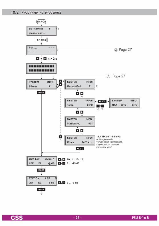
10.2 proGramminGproCedure
B
Ein / On
BE–Remote
please wait …
V 45
Box …
– – –
– – –
– – –
t > 10 st > 10 s
SYSTEM
BErem
INFO:
V 45
A
+ t > 2 s
A
M
B
STATION
LEVEL
LEVEL:
-3 dB
STATION
001
NUMBER:
BOX LEVEL
LEVEL
Bx 1
-6 dB /
0 … -25 dB
0 … -6 dB
Bx 1 … Bx 12
SYSTEM
OFF
MODEM:
ON / OFF
SYSTEM
PASSWORD
SECURE:
0000 /
INFO:
V 1
SYSTEM
Output-Coll.
SYSTEM
Clock
INFO:
14.7 MHz
°C / °F
INFO:
21°C
SYSTEM
Temp.
INFO:
001
SYSTEM
Station Nr.
14.7 MHz o. 16.0 MHzAbhängig von der verwendeten Taktfrequenz.Dependent on the clock frequency used.
SYSTEM
MAX 68°C
INFO:
84°C
.
Page 27
Page 27

-26- PSU8-16R
messaGeaftertemperatureexCeedinG
Instead of the standby "BE-Remote" menu the "ATTENTION" menu is displayed.
B
Ein / On
BE–Remote
please wait …
V 45
Box …
– – –
– – –
– – –
t > 10 st > 10 s
SYSTEM
BErem
INFO:
V 45
A
+ t > 2 s
A
M
B
STATION
LEVEL
LEVEL:
-3 dB
STATION
001
NUMBER:
BOX LEVEL
LEVEL
Bx 1
-6 dB /
0 … -25 dB
0 … -6 dB
Bx 1 … Bx 12
SYSTEM
OFF
MODEM:
ON / OFF
SYSTEM
PASSWORD
SECURE:
0000 /
INFO:
V 1
SYSTEM
Output-Coll.
SYSTEM
Clock
INFO:
14.7 MHz
°C / °F
INFO:
21°C
SYSTEM
Temp.
INFO:
001
SYSTEM
Station Nr.
14.7 MHz o. 16.0 MHzAbhängig von der verwendeten Taktfrequenz.Dependent on the clock frequency used.
SYSTEM
MAX 68°C
INFO:
84°C
.
Page 26
! ! ! ATTENTION ! !
Temp.1 68°C
A
M
SYSTEM
MAX 68°C
INFO:
84°C
INFO:
21°C
SYSTEM
Temp.
Angezeigte Maximaltemperatur (z.B . 68 °C) löschen (t > 3 s).Deleting maximum temperature (e.g. 68 °C) displayed (t > 3 sec).
Aktuelle Temperatur Current temperature
Page 26

-27- PSU8-16R
10.3 proGramminGthehead-endstation
—> Pressing the button for longer than 2 seconds cancels the programming procedure. This takes you back to the program item "Activating system information" from any menu. Any entries that have not been saved are reset to the previous settings.
—> Entries in the menus can be saved by pressing the key. You are taken back to the "Activating system information" menu item.
• Switch on the head-end station.
Ein / On
BE–Remote
please wait …
V 45
t > 10 st > 10 s
—> The display shows the software version of the head-end station (e.g. "V45").
—> The processor reads the cassettes‘ data (approx. 10 seconds).
-28- PSU8-16R
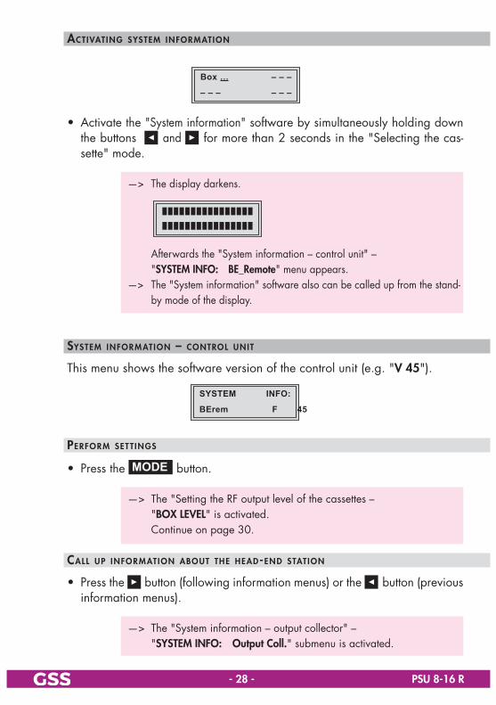
aCtivatinGsysteminformation
Box …
– – –
– – –
– – –
• Activate the "System information" software by simultaneously holding down the buttons and for more than 2 seconds in the "Selecting the cas-sette" mode.
—> The display darkens.
Afterwards the "System informatio n – control unit" – "SYSTEMINFO: BE_Remote" menu appears.—> The "System information" software also can be called up from the stand-
by mode of the display.
systeminformation–Controlunit
This menu shows the software version of the control unit (e.g. "V45").
SYSTEM
BErem
INFO:
V 45
performsettinGs
• Press the button.
—> The "Setting the RF output level of the cassettes – "BOXLEVEL" is activated. Continue on page 30.
Callupinformationaboutthehead-endstation
• Press the button (following information menus) or the button (previous information menus).
—> The "System information – output collector" – "SYSTEMINFO: OutputColl." submenu is activated.

-29- PSU8-16R
systeminformation–outputColleCtor
This menu shows the software version of the output collector (e.g. "V1").
INFO:
V 1
SYSTEM
Output-Coll.
• Press the button.
—> The "System information – temperature" – "SYSTEMINFO: Temp." submenu is activated.
systeminformation–temperature
This menu shows the temperature inside the head-end station. Additionally the temperature display can be switched from degree Celsius to degree Fahren-heit and the highest inner temperatures recorded to date can be displayed.
INFO:
21°C
SYSTEM
Temp.
SYSTEM
MAX 68°C
INFO:
84°C
• Using the buttons set the temperature display wished. • To activate the highest inner temperatures press the button.
—> Press the button again to return to the previous menu.
• Press the button.
—> The "System information – number of the head-end station" – "SYSTEMINFO: StationNr." submenu is activated.
-30- PSU8-16R
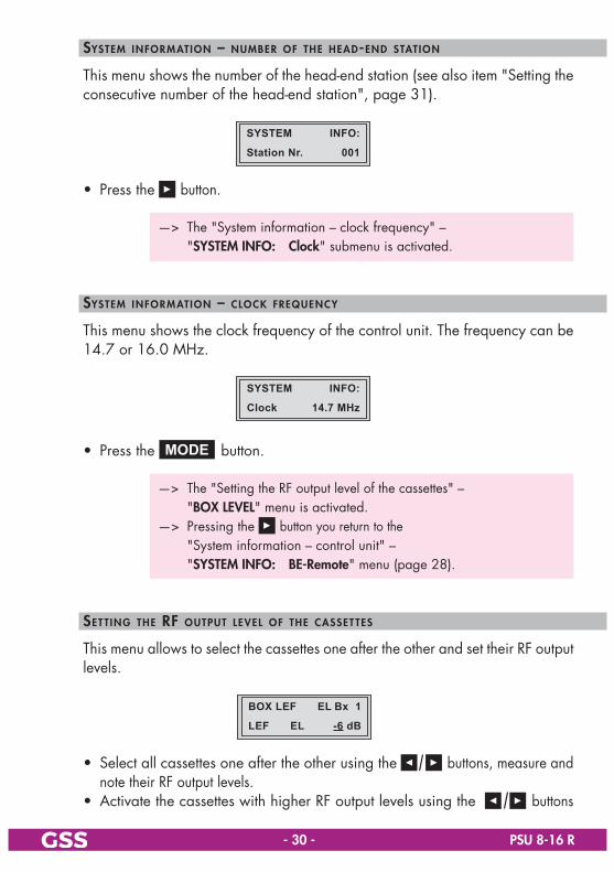
systeminformation–numberofthehead-endstation
This menu shows the number of the head-end station (see also item "Setting the consecutive number of the head-end station", page 31).
INFO:
001
SYSTEM
Station Nr.
• Press the button.
—> The "System information – clock frequency" – "SYSTEMINFO: Clock" submenu is activated.
systeminformation–CloCkfrequenCy
This menu shows the clock frequency of the control unit. The frequency can be 14.7 or 16.0 MHz.
SYSTEM
Clock
INFO:
14.7 MHz
• Press the button.
—> The "Setting the RF output level of the cassettes" – "BOXLEVEL" menu is activated.—> Pressing the button you return to the "System information – control unit" – "SYSTEMINFO: BE-Remote" menu (page 28).
settinGtherfoutputleveloftheCassettes
This menu allows to select the cassettes one after the other and set their RF output levels.
BOX LEVEL
LEVEL
Bx 1
-6 dB
• Select all cassettes one after the other using the buttons, measure and note their RF output levels.
• Activate the cassettes with higher RF output levels using the buttons

-31- PSU8-16R
and equal their RF output levels to the value of the cassette with the lowest RF output level using the buttons ("0…-25dB")
• Press the button.
—> The "Setting the RF output level of the head-end station" – "STATION LEVEL:" menu is activated.
settinGtherfoutputlevelofthehead-endstation
This menu allows to set the RF output level of the head-end station to the require-ments of the cable system.
STATION
LEVEL
LEVEL:
-3 dB
• Set the RF output level of the head-end station using the buttons ("0…-6dB").
• Press the button.
—> The "Setting the consecutive number of the head-end station" – "STATION NUMBER:" menu is activated.
settinGtheConseCutivenumberofthehead-endstation
If several head-end stations are used in a cable system the head-end stations must get a consecutive number to identify them if the PSW 1000 software is used.
STATION
001
NUMBER:
• Use the buttons to set the consecutive number.
• Press the button.
—> The "Activating the modem connection" – "SYSTEM MODEM:" menu is activated.

-32- PSU8-16R
aCtivatinGthemodemConneCtion
If the head-end station is to be remote controlled using the PSW 1000 con-figuration software and a modem connected to the head-end station (without PRCU 8 / RCU 1 / PRCU 12) activate the modem mode in this menu ("ON").
SYSTEM
OFF
MODEM:
• Using the buttons switch on the modem mode "ON" or if necessary switch it "OFF".
—> If no modem is found "NOTFOUND" is displayed.
• Press the button.
—> The "Setting the password" – "SYSTEM SECURE:" menu is activated.
settinGthepassword
In this menu the access to the software of the control unit and the cassettes can be refused.
SYSTEM
PASSWORD
SECURE:
0000
• Use the buttons to place the cursor under the digits to be set for the password.
• Use the buttons to set the digits of the password wished.

-33- PSU8-16R
savinGsettinGs
• Press the button.
—> The settings are saved.—> You return to the "Activating system information" menu item (page 28).—> By pressing the button, you will be returned to the menu
item "System information – control unit" without saving the pro-grammed data (page 28).
proGramminGthehead-endstation(followinGexCesstemperature)
If the maximum permissible temperature for the head-end station (inner tempera-ture) is exceeded, "ATTENTION" appears in the display instead of the "BE-Remote" standby display.
In this operating state, the menus for the cassettes and operating unit are locked. To be able to access the menus for the cassettes and operating unit, the software needs to be unlocked.
Thecauseoftheexcesstemperaturemustbedeterminedandtheappropriatecorrectivemeasurestakenforthehead-endstationtooperatesmoothlyagain(e.g.additionalventilation,airconditioning).
In the "ATTENTION" menu, the number of the particular head-end station (e.g. "Temp.1") and the temperature (e.g. "68°C") are displayed.
! ! ! ATTENTION ! !
Temp.1 68°C
• Press the button.
—> The "System information" – "SYSTEM INFO:" menu is activated.
-34- PSU8-16R
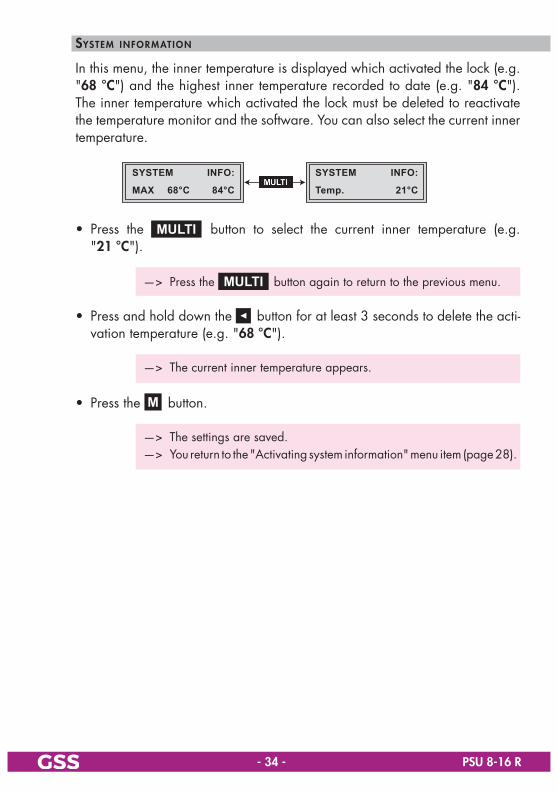
systeminformation
In this menu, the inner temperature is displayed which activated the lock (e.g. "68°C") and the highest inner temperature recorded to date (e.g. "84°C"). The inner temperature which activated the lock must be deleted to reactivate the temperature monitor and the software. You can also select the current inner temperature.
SYSTEM
MAX 68°C
INFO:
84°C
INFO:
21°C
SYSTEM
Temp.
• Press the button to select the current inner temperature (e.g. "21 °C").
—> Press the button again to return to the previous menu.
• Press and hold down the button for at least 3 seconds to delete the acti-vation temperature (e.g. "68°C").
—> The current inner temperature appears.
• Press the button.
—> The settings are saved.—> You return to the "Activating system information" menu item (page 28).
-35- PSU8-16R
10.4 proGramminGviatheControlsoftware
—> For basic operations of the software please note the operating in-structions PSW 1000.
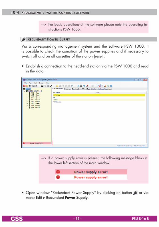
redundantpowersupply
Via a corresponding management system and the software PSW 1000, it is possible to check the condition of the power supplies and if necessary to switch off and on all cassettes of the station (reset).
• Establish a connection to the head-end station via the PSW 1000 and read in the data.
—> If a power supply error is present, the following message blinks in the lower left section of the main window.
• Open window "Redundant Power Supply" by clicking on button or via menu Edit>RedundantPowerSupply.
-36- PSU8-16R
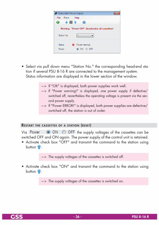
• Select via pull down menu "Station No." the corresponding head-end sta-tion if several PSU 8-16 R are connected to the management system.
Status information are displayed in the lower section of the window.
—> If "OK" is displayed, both power supplies work well.—> If "Power warning!" is displayed, one power supply if defective/
switched off, nevertheless the operating voltage is present via the sec-ond power supply.
—> If "Power ERROR!" is displayed, both power supplies are defective/switched off, the station is out of order.
restarttheCassettesofastation(reset)
Via the supply voltages of the cassettes can be switched OFF and ON again. The power supply of the control unit is retained.
• Activate check box "OFF" and transmit the command to the station using button .
—> The supply voltages of the cassettes is switched off.
• Activate check box "ON" and transmit the command to the station using button .
—> The supply voltages of the cassettes is switched on.

-37- PSU8-16R
stationConfiGuration
The output level of stations and cassettes equipped with an electronic level controller can be set via this menu. The stored maximum temperature can be reset.
—> If button becomes "active" after selecting a station in the left window (tree structure) of the 1000 the station is equipped with an electronic level controller.
Access for this menu is only possible via this button.—> The setting of the output level of cassettes is possible from the control
units software version V44 (BE-Remote) on.
• Click to button an.
• Adjust the output level of the station via buttons to the desired value (0…-6dB).
• Adjust the output level of the corresponding cassette via the corresponding buttons to the desired value (-25…0dB).
• Activate the check box "Reset" in order to reset the stored temperature. • Send the setting to the station .
—> Using button the current values of the plant can be read out again.

-38- PSU8-16R
11 finalproCedures
Afterinstallingthehead-endstation,upgradingaccessoriesorinstallingcas-settesitisnecessarytotightenallcableconnections,cableterminalsandcoverscrewsinordertomaintaincompliancewithcurrentEMCregulationssecurely.
• Securely tighten the cable connections (Cinch, RF connectors) using an ap-propriate open-ended spanner.
• Hang the front cover into the mounting screws 2. • Tighten the mounting screws. • Attach the locking screws 1 and tighten it
2 21
Toavoiddisturbancesandproblemsinreceptionintheconnectedcablenet-work,itisabsolutelynecessarytoadjusttheoutputlevelofthecompletere-ceivinginstallationtothenecessarylinearvalues(forexampleFM,64QAM8-16dBand256QAM4-6dBbelowtheanalogouslevel)!

DeclarationofCEconformity
GSS Grundig Systems GmbH • Beuthener Straße 43 • D-90471 Nuremberg
CLASSCLASS
KLASSE
KLASSE
Phone: +49 (0) 911 / 703 8877 • Fax: +49 (0) 911 / 703 9210www.gss.de/en • [email protected] Service: Phone: +49 (0) 911/703 2221; Fax: +49 (0) 911/703 2326; [email protected]
Alterations reserved. Technical data E. & O.E. © by GSS Grundig Systems GmbH 001/2017