Embed Size (px)
Citation preview

WARRANTY
Hobbico guarantees this kit to be free from defects in both material and workmanship at the date of purchase. This warranty does not cover anycomponent parts damaged by use or modification. In no case shall Hobbico's liability exceed the original cost of the purchased kit. Further, GreatPlanes reserves the right to change or modify this warranty without notice.
In that Hobbico has no control over the final assembly or material used for final assembly, no liability shall be assumed nor accepted for any damageresulting from the use by the user of the final user-assembled product. By the act of using the user-assembled product, the user accepts all resulting liability.
If the buyer is not prepared to accept the liability associated with the use of this product, the buyer is advised to return this kit immediately in newand unused condition to the place of purchase.
ASSEMBLY INSTRUCTIONS
TM
© Copyright 2003 HCAZ3064 for HCAA2125 V1.1
Specifications:Wingspan: 71 in [1805mm]Wing Area: 888 sq in [57 dm2]Weight: 7 - 8 lb [3180 - 3630g]Wing Loading: 18 - 21 oz/sq ft [55 - 64 g/dm2]Length: 55 in [1400mm]Radio: 4-channel with 4 servosEngine: .60 to .65 cu in [10.0 – 10.6cc] two-stroke
READ THROUGH THIS MANUAL BEFORESTARTING CONSTRUCTION. IT CONTAINSIMPORTANT INSTRUCTIONS AND WARNINGSCONCERNING THE ASSEMBLY AND USE OFTHIS MODEL.
1610 Interstate DriveChampaign, IL 61822(217) 398-8970, Ext. 2
See more of our products at www.hobbico.com

2
INTRODUCTION.................................................2SAFETY PRECAUTIONS........................................3ADDITIONAL ITEMS REQUIRED.........................3Radio system ........................................................3Engine ..................................................................3Tools, Building Supplies, Accessories....................4Optional Supplies and Tools .................................4Field Equipment....................................................4KIT INSPECTION .................................................5ORDERING REPLACEMENT PARTS......................6TIGHTEN THE COVERING...................................7PREPARATIONS ...................................................7ASSEMBLE THE WING .........................................8Join the ailerons....................................................8 Join the wing ........................................................9ASSEMBLE THE FUSELAGE.................................10Mount the stabilizer and fin................................10Mount the landing gear .....................................13Mount the engine ...............................................14Install the fuel tank .............................................15Mount the aileron servo......................................15Hook up the controls..........................................16Mount the muffler, prop and spinner ..................19PREPARE THE MODEL FOR FLYING ..................20Balance the model (C.G.) ...................................20Center the servos ................................................21Check the control directions...............................22Center the control surfaces .................................22Adjust the throttle ...............................................23Set the control throws.........................................23Identify your model ............................................24Balance Propellers ..............................................24Checklist.............................................................25Charge the batteries............................................25Gather your tools................................................25FLIGHT PREPARATION......................................25Check the controls..............................................25Range check .......................................................26Ground check.....................................................26ENGINE SAFETY PRECAUTIONS .......................26AMA SAFETY CODE...........................................27FLYING...............................................................27Taxiing ..................................................Back CoverTakeoff ..................................................Back CoverFlight.....................................................Back CoverLanding.................................................Back CoverMAINTENANCE TIPS............................Back Cover
Congratulations and thank you for purchasing theHobbico Hobbistar .60 MKIII. You've made the rightdecision by purchasing a “real” model airplane thatuses a .60-size engine and a 4-channel radio. Onceassembled and set up, there will be no fiddling with atemperamental engine or constant troubleshooting tofigure out how to get the model to fly. Under theguidance of a flight instructor, all you'll have to do isconcentrate on learning to fly. And after you'vemastered the Hobbistar, the engine and radio may beinstalled in your next model!
IMPORTANT:The best thing you can do to insure success is tofind a flight instructor who will inspect yourmodel for airworthiness and provide flyinglessons. It cannot be stated strongly enough that,if you do not already know how to fly an R/Cairplane, you will probably not be able to fly thismodel by yourself. It may appear to be easy, butover-controlling and disorientation quicklyovercome inexperienced fliers swiftly ending theirfirst flight. If you haven't yet done so, contact thelocal hobby shop and ask them to introduce youto an instructor or an R/C club representative. Ifthere is no club or experienced R/C pilot nearby,it would be worth even a long drive to find one-ifonly for just a few flight lessons (then you'll havean idea of what to expect).
If there is no hobby shop in your area, contact theAMA (Academy of Model Aeronautics), thegoverning body of model aeronautics. The AMAcan direct you to the closest R/C club whosemembership should have qualified flightinstructors. With the added benefit of insurancecoverage provided by the AMA, most clubsrequire AMA membership to fly at their field.
Academy of Model Aeronautics5151 East Memorial DriveMuncie, IN 47302-9252
Tele. (800) 435-9262Fax (765) 741-0057
Or via the Internet at: http://www.modelaircraft.org
IntroductionTable of Contents

3
1. Your Hobbistar .60 MKIII should not beconsidered a toy, but rather a sophisticated, workingmodel that functions very much like a full-sizeairplane. Because of its performance capabilities,the Hobbistar .60 MKIII, if not assembled andoperated correctly, could possibly cause injury toyourself or spectators and damage to property.
2. You must assemble the model according to theinstructions. Do not alter or modify the model, asdoing so may result in an unsafe or unflyable model.In a few cases the instructions may differ slightlyfrom the photos. In those instances the writteninstructions should be considered as correct.
3. You must take time to build straight, true and strong.
4. You must use an R/C radio system that is in first-class condition, and a correctly sized engine andcomponents (fuel tank, wheels, etc.) throughout thebuilding process.
5. You must correctly install all R/C and othercomponents so that the model operates correctly onthe ground and in the air.
6. You must check the operation of the model beforeevery flight to insure that all equipment is operatingand that the model has remained structurally sound. Besure to check clevises or other connectors often andreplace them if they show any signs of wear or fatigue.
7. If you are not already an experienced R/C pilot,you should fly the model only with the help of acompetent, experienced R/C pilot.
These are the items not supplied with the Hobbistar .60MKIII that must be purchased separately. Whereappropriate, order numbers are provided in parentheses.
RADIO SYSTEM
A 4-channel radio control system with four servos isrequired to fly the Hobbistar .60 MKIII. 4 “channels”means that the radio is capable of operating fourcontrols. On a trainer model such as the Hobbistarthe controls are the ailerons, elevator, throttle andrudder. Some 4-channel radio control systemsinclude only three servos, so a fourth servo mayhave to be purchased separately.
ENGINE
A .60 to .65 cu in two-stroke model airplane engineis required to fly the Hobbistar .60 MKIII. Basically,there are two types of two-stroke engines; “ballbearing” and “non ball bearing” engines. In additionto having a crankshaft supported by two ballbearings, most ball bearing engines have otherperformance features that boost power and RPM(and price). For the Hobbistar .60 MKIII, aneconomical, non ball bearing engine is more thansuitable. Should you decide to go “all-out” and
Items Required
We, as the kit manufacturer, provide you with atop quality kit and instructions, but ultimately thequality and flyability of your finished modeldepends on how you build it; therefore, wecannot in any way guarantee the performance ofyour completed model, and no representationsare expressed or implied as to the performance orsafety of your completed model.
Protect Your Model, Yourself & OthersFollow these Important
Safety Precautions

purchase a more powerful ball bearing engineanyway, you’ll have to remember to throttle back toslow the model while learning to fly. A suitablepropeller and spare propellers will also be required(most two-stroke .60 engines run well with a 12 x 6or 11 x 7 propeller, but refer to the recommendationsin the instructions that came with the engine).
TOOLS, BUILDING SUPPLIES AND ACCESSORIESThese are the rest of the items required to assemblethe Hobbistar .60 MKIII.
❏ 6" [150mm] servo extension (HCAM2701 for Futaba®)❏ R/C foam rubber (1/4" [6mm] - HCAQ1000, or
1/2" [13mm] - HCAQ1050)❏ Medium silicone fuel tubing (GPMQ4131)❏ #64 rubber bands (1/4 lb [113g] box, HCAQ2020)❏ Stick-on segmented lead weights (GPMQ4485)❏ Threadlocker thread locking cement (GPMR6060)❏ 1/2 oz. [15g] Thin Pro™ CA Glue (GPMR6001)❏ 1/2 oz. [15g] Medium Pro CA+ Glue (GPMR6007) ❏ Pro 30-minute epoxy (GPMR6047) ❏ Denatured alcohol (for epoxy clean up)❏ #1 Hobby knife (HCAR0105)❏ #11 blades (5-pack, HCAR0211) ❏ #1 Phillips screwdriver (HCAR1022)❏ #2 Phillips screwdriver (HCAR1024)❏ Pliers❏ Small metal file❏ Masking tape❏ 12mm (or appropriate size) prop wrench or
crescent wrench❏ Drill and drill bits: 1/16" [1.6mm], 5/64" [2mm],
3/32" [2.4mm], #19 (or 11/64") [4.4mm]
OPTIONAL SUPPLIES AND TOOLS These items are not absolutely required, but arementioned in the instructions and will help youassemble the Hobbistar .60 MKIII
❏ Top Flite® MonoKote® sealing iron (TOPR2100) ❏ Top Flite Hot Sock iron cover (TOPR2175)❏ 4 oz. [113g] aerosol CA activator (GPMR634)❏ CA applicator tips (HCAR3780)❏ CA debonder (GPMR6039)❏ Epoxy brushes (6, GPMR8060)❏ Mixing sticks (50, GPMR8055)❏ Mixing cups (GPMR8056)❏ Builder's Triangle Set (HCAR0480)
❏ Pliers with wire cutter (HCAR0630)❏ Masking tape (TOPR8018)❏ K & S #801 Kevlar thread (for stab alignment,
K+SR4575)❏ Panel Line Pen (TOPQ2510)❏ CG Machine™ (GPMR2400)❏ Precision Magnetic Prop Balancer™ (TOPQ5700)❏ Prop Reamer (GPMQ5005)
FIELD EQUIPMENT
When ready to fly, you'll need the equipment to fuelthe plane and start the engine. Perhaps you've alreadymade arrangements with the R/C club or your flightinstructor to borrow theirs, but eventually you'll wantto get your own. Refer to your hobby dealer forspecific recommendations on what to purchase.Following is a list of the most important items…
❏ Model engine glow fuel (5%, 10% or 15%nitromethane content is suitable)
❏ Hand-crank or electric fuel pump system withfuel lines and fittings for transferring fuel from thecontainer into the fuel tank in the model.
❏ Glow plug igniter for starting the engine❏ Battery for glow plug igniter (if not already
attached to igniter)❏ Electric starter and 12v battery❏ Field box for carrying starting equipment and tools
4

5
1
2
2
6
510
97
15
14
8
11
1213
34
Kit Inspection
1. Fuselage 2. R&L wing halves w/ailerons3. Stab w/elevator4. Fin w/rudder5. Main landing gear wires (2)6. Nose gear wire7. Fuel tank w/hardware
8. 1/4" x 1/2" x 10" [6 x 12 x 255mm]balsa stick (fuel tank, receiver,battery mounting) (2)
9. Cast aluminum engine mount10. 2-3/4" [70mm] foam wheels (3)11. 2-3/4" [70mm] white plastic
spinner w/4 spinner screws
12. 1/8" [3.2mm] plywood fuselageservo tray
13. 1/8" [3.2mm] plywood wingservo tray
14. 1/8" [3.2mm] plywood wingjoiners (3)
15. Hardwood wing dowels (2)
Before starting to build, take an inventory of all the parts to make sure the kit is complete and inspect theparts to make sure they are of acceptable quality. If any parts are missing or are not of acceptable quality,or if you need assistance with assembly, contact Product Support. When reporting defective or missingparts, use the part names exactly as they are written in the Kit Contents list on this page.
Product Support:Telephone: (217) 398-8970
Fax: (217) 398-7721E-mail: [email protected]
Parts Photographed
(1) nylon nose steering arm (1) nylon nose gear mount (2) 2mm x 9-7/8" [250mm] threaded one-end
wire aileron pushrods(1) 2mm x 27" [685mm] threaded one-end wire
throttle pushrod (1) 2mm x 19-3/4" [500mm] wire nose wheel
steering pushrod(2) nylon aileron torque rod horns(2) nylon straps (main landing gear)(5) nylon clevises(5) nylon pushrod keepers(2) nylon control horns w/mnt plates(5) silicone retainers for clevises (15) precut CA hinges
(4) 4 x 25mm Phillips-head screws (enginemounting)
(6) 4 x 20mm Phillips-head screws (enginemount, nose gear bearing)
(10) 4mm lock washer(10) 4mm flat washer(4) 4mm nut(2) 2 x 16mm Phillips-head machine screws
(rudder control horn mnt)(2) 2 x 20mm Phillips-head machine screws
(elevator control horn mnt)(4) 3 x 12mm Phillips-head self-tapping screws
(main LG straps)(4) 5mm wheel collars (main wheels)(5) 4mm wheel collars (nose wheel)
(10) 3 x 5mm screw (for screw-lock connector,wheel collars)
(1) 3 x 8mm screw (nose steering collar)(2) 2mm washer (for pushrod connector)(2) pushrod connector (screw-lock type)(2) thumb nuts (for pushrod connectors)(2) metal engine mount straps(2) aileron torque rods (factory installed in wing)(6) 4mm blind nuts (factory installed in firewall)(1) 13-1/2" [340mm] plastic pushrod tube (throttle)(1) 11-1/4" [285mm] plastic pushrod tube (for
nose wheel)(2) 36" [915mm] threaded one-end pushrods
(elevator, rudder)
Parts Not Photographed

0" 1" 2" 3" 4" 5"
0 10 20 30 40 50 60 70 80 90 100 110 120 130
Inch Scale
Metric Scale
6
Ordering Replacement Parts
To order replacement parts for the Hobbico Hobbistar .60 MKIII ARF, use the order numbers in theReplacement Parts List that follows. Replacement parts are available only as listed. Not all parts areavailable separately (an aileron cannot be purchased separately, but is only available with the wing kit).Replacement parts are not available from Product Support, but can be purchased from hobby shops or mailorder/Internet order firms. Hardware items (screws, nuts, bolts) are also available from these outlets. If youneed assistance locating a dealer to purchase parts, visit www.hobbico.com and click on “Where to Buy.”If this kit is missing parts, contact Product Support.
Item Description How to PurchaseMissing pieces Contact Product SupportInstruction manual Contact Product SupportPlans Construction Plans Not availableHardware Individual hardware items Contact your hobby supplierParts listed below Contact your hobby supplier
HCAA3120 Fuselage Set (Fuselage, servo tray,wing dowels(2))HCAA3121 Wing Set (Right & left wing panels w/ailerons, hinges (8), plywood wing
joiners (3), aileron servo tray)HCAA3122 Tail Set (Fin & rudder, stab & elevator, hinges (7))HCAA3123 Landing Gear Set (5mm main gear wires (2), 4mm nose gear wire, 5mm wheel
collars & screws (4), 4mm wheel collars & screws (2))
The Hobbistar .60 MKIII ARF is factory-covered with iron-on heat shrinkable model airplane covering.Should repairs ever be required, the covering can be patched with Top Flite MonoKote or other similarmodel airplane covering that has an iron-on adhesive on the back and shrinks with heat. Most coveringsare packaged in six-foot rolls, but some hobby shops sell covering by the foot. If only a small piece isneeded for a minor patch, perhaps a fellow modeler would give you some.
To convert inches to millimeters, multiply inches by 25.4
1/64" = .4mm1/32" = .8mm1/16" = 1.6mm3/32" = 2.4mm1/8" = 3.2mm
5/32" = 4mm
3/16" = 4.8mm1/4" = 6.4mm3/8" = 9.5mm1/2" = 12.7mm5/8" = 15.9mm3/4" = 19mm
1" = 25.4mm2" = 50.8mm3" = 76.2mm6" = 152.4mm
12" = 304.8mm15" = 381mm
18" = 457.2mm21" = 533.4mm24" = 609.6mm30" = 762mm36" = 914.4mm
Metric Conversions
Examine the covering on the model. Occasionally,the covering requires tightening to remove wrinklesthat develop. If necessary, use a model airplanecovering iron with a covering sock to tighten thecovering and remove wrinkles. Hint: Poke three orfour pin holes in the covering between the “ribs” inthe tail surfaces, allowing air to escape to fullytighten the covering. Note: If you haven't yetpurchased a covering iron (or borrowed one from afriend), this step may be done later.
There are a few steps that require 30-minute epoxythat can be done first to speed assembly.
❏ 1. Use 30-minute epoxy to glue together the three1/8" [3.2mm] plywood wing joiners. Be certain to
apply epoxy to all mating surfaces. (In other words,apply epoxy to both sides of the joiner in the middleand to the inside of both the joiner on the top and thejoiner on the bottom.) Hold the joiners together withclamps. Wipe away excess epoxy before it hardens.
❏ 2. Round the ends of both 1/4" [6.5mm] wingdowels. Cut the covering from the holes in thefuselage for the dowels and glue them into positionwith 30-minute epoxy. Lightly coat the dowels withepoxy. (Only the front dowel is shown in the photo,but there is a dowel at the aft end of the cutout in thefuselage for the wing.)
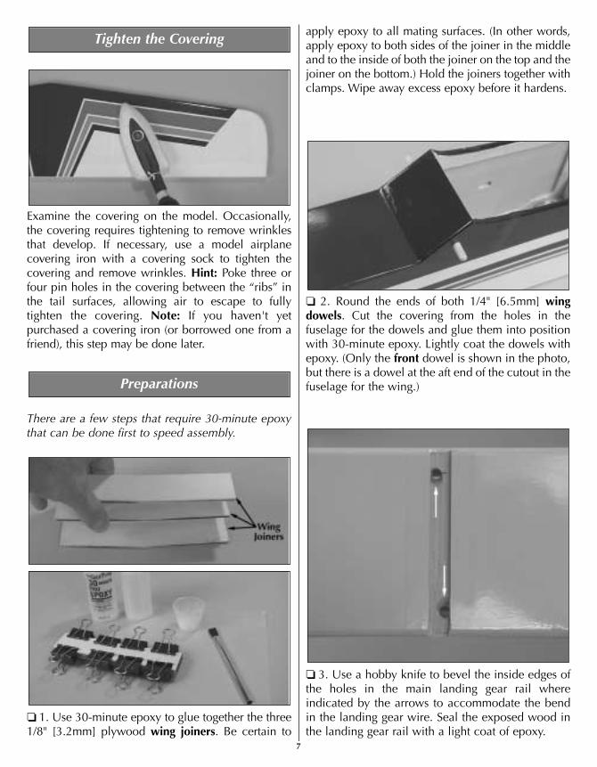
❏ 3. Use a hobby knife to bevel the inside edges ofthe holes in the main landing gear rail whereindicated by the arrows to accommodate the bendin the landing gear wire. Seal the exposed wood inthe landing gear rail with a light coat of epoxy.
Preparations
Tighten the Covering
7

❏ 4. Seal the edges of the covering around theengine compartment with a thin coat of 30-minuteepoxy. Also use 30-minute epoxy to lightly coat theinside of the fuselage all the way around theopening for the wing (as indicated by the shadedarea). This will fuelproof the bare wood in caseengine exhaust residue seeps in.
JOIN THE AILERONS
Start with the right wing so yours matches thephotos the first time through.
❏ ❏ 1. Use a hobby knife with a #11 blade to neatlytrim the covering from the bottom of the right wingaround the aileron torque rod to allow full, unrestrictedmovement of the rod.
❏ ❏ 2. Test fit the aileron to the wing with four CAhinges but do not glue them in yet. If it is difficult tojoin the aileron to the wing because the hinge slotsare too tight, remove the hinges. Widen the hingeslots by inserting a #11 blade and moving it backand forth a few times.
❏ ❏ 3. Remove the aileron from the wing. Drill a3/32" [2.4mm] hole 1/2" [13mm] deep in the centerof the hinge slots to allow the thin CA used for gluingin the hinges to fully “wick” all the way in. Cut a smallstrip of covering from all the hinge slots in the wingand aileron. For the best result, use a high-speed toolsuch as a Dremel to drill the holes.
AWAY FROM THE SLOTCUT THE COVERING
DRILL A 3/32" HOLE1/2" DEEP, IN CENTER
OF HINGE SLOT
Assemble the Wing
8

❏ ❏ 4. Tape a small piece of wax paper or a piece ofplastic from a sandwich bag to the wing under theaileron torque rod. Coat the “arm” portion of thetorque rod and the hole and the slot in the aileron forthe torque rod with 30-minute epoxy. Immediatelyproceed to the next step.
❏ ❏ 5. Join the aileron to the torque rod and wingwith the hinges. If the hinges don't remain centered,stick a pin through the hinge to hold it in position.Be certain there is a small gap between the aileronand the wing—just enough to slip a piece of paperthrough or to see light through. Remove any pinsthat were used to center the hinges.
❏ ❏ 6. Apply six drops of thin CA to both sides of allthe hinges. Allow a few seconds between drops sothe CA fully soaks into the hinge rather than being
drawn into the hinge gap thus gluing the aileron tothe wing. Note the CA applicator tip (HCAR3780)on the CA bottle to control and pinpoint the CA thatcomes out.
❏ ❏ 7. Stack a few paper towels over each other andcut them into approximately 2" [50mm] squares.Moisten one of the squares with denatured alcoholand use it to wipe away excess epoxy that came outof the aileron.
❏ 8. Return to step 1 and join the left aileron to theleft wing panel the same way.
JOIN THE WING
❏ 1. Test fit the aileron servo in both wing halves tomake sure the servo fits. If necessary, enlarge the cutouts in the wing to accommodate the servo.
❏ 2. Test fit the wing joiner you glued together earlierinto both wing halves, then test fit the wing halveswith the joiner. There should be no gap in the wing.
2-3/8" (± 3/8")
9
THIN CA

Make certain the joiner is installed upright (so thewing tips are higher than the middle of the wing).Make adjustments where necessary for a good fit(sanding the top and bottom of the joiner to even theedges or remove excess epoxy may be required).Note: The wing dihedral (or upward angle betweenthe joining wing halves) is factory set and isdetermined by the shape of the wing joiners.However, some modelers prefer to check the wingdihedral anyway. To do so, lay one wing half on a flatsurface. As shown in the sketch, the end of the otherwing (not including the wing tip) should be 2-3/8"above the surface. A variance of approximately 3/8"is acceptable.
❏ 3. Separate the wing halves and remove thejoiner. Thoroughly coat the end of one wing half andthe inside of the wing where the joiner fits with 30-minute epoxy. Also coat one half of the joiner all theway around. Install the coated end of the joiner intothe wing half. Proceed immediately to the next step.
❏ 4. Coat the inside and the end of the other wingwith 30-minute epoxy. Also coat the end of thejoiner that is sticking out of the other wing half. Fitthe wings together.
❏ 5. Tightly hold both wing halves together withseveral strips of masking tape on both the top andbottom of the wing. Be certain the leading andtrailing edges of the wing align. As you apply the tape,wipe away excess epoxy that comes out. Do notdisturb the wing until the epoxy has fully hardened.
MOUNT THE STABILIZER AND FIN
❏ 1. The same as was done for the wing and ailerons,prepare the stabilizer and elevator and fin and rudderfor hinging (by test fitting the hinges, cutting a strip ofcovering from the slots and drilling the holes). Do notglue in the hinges until instructed to do so.
❏ 2. Cut the covering from the slots in the fuselagefor the stabilizer and fin. Also cut the covering fromthe pushrod tubes on the top and left side of the fuse(where indicated by the arrows in the photo).
❏ 3. Taking accurate measurements, mark the centerof the stab on the trailing edge. Position the stab inthe fuselage. Center the mark on the trailing edgewith the end of the fuse.
Assemble the Fuselage
10
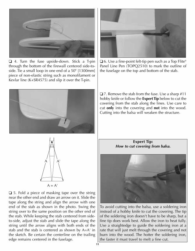
❏ 4. Turn the fuse upside-down. Stick a T-pinthrough the bottom of the firewall centered side-to-side. Tie a small loop in one end of a 50" [1300mm]piece of non-elastic string such as monofilament orKevlar line (K+SR4575) and slip it over the T-pin.
❏ 5. Fold a piece of masking tape over the stringnear the other end and draw an arrow on it. Slide thetape along the string and align the arrow with oneend of the stab as shown in the photo. Swing thestring over to the same position on the other end ofthe stab. While keeping the stab centered from side-to-side, adjust the stab and slide the tape along thestring until the arrow aligns with both ends of thestab and the stab is centered as shown by A=A' inthe sketch. Be certain the centerline on the trailingedge remains centered in the fuselage.
❏ 6. Use a fine-point felt-tip pen such as a Top Flite®
Panel Line Pen (TOPQ2510) to mark the outline ofthe fuselage on the top and bottom of the stab.
❏ 7. Remove the stab from the fuse. Use a sharp #11hobby knife or follow the Expert Tip below to cut thecovering from the stab along the lines. Use care tocut only into the covering and not into the wood.Cutting into the balsa will weaken the structure.
Expert Expert TTip:ip:How to cut covering from balsa.
To avoid cutting into the balsa, use a soldering ironinstead of a hobby knife to cut the covering. The tipof the soldering iron doesn't have to be sharp, but afine tip does work best. Allow the iron to heat fully.Use a straightedge to guide the soldering iron at arate that will just melt through the covering and notburn into the wood. The hotter the soldering iron,the faster it must travel to melt a fine cut.
A'A
A = A'
11

❏ 8. Peel the covering from the stab. Remove anyink left on the stab with one of the small paper towelsquares you cut earlier, moistened with denaturedalcohol. Also remove any ink around the slot for thestab that may be on the fuselage.
❏ 9. Mount the wing to the fuselage with a coupleof #64 rubber bands. Slide the stab back into thefuselage. Stand eight to ten feet behind the modeland observe the alignment between the stab andwing. If the stab does not align with the wing, placea small weight on the “high side” of the stab to bringit into alignment. If weight is not enough to tilt thestab to one side, remove the stab from the fuselage.Carefully sand the slot in the fuselage as necessaryto get the stab to align with the wing.
❏ 10. Thoroughly coat the slot in the fuselage for thestab and the stab where it contacts the fuselage with
30-minute epoxy. Working quickly, slide the stabinto position. Wipe off any epoxy deposited on thestab. Use the pin and string to be certain the stab isin alignment. Use a small clamp to hold the stab inposition until the epoxy hardens.
❏ 11. The same as was done to the stab, trim thecovering from both sides of the fin where it will beglued into the fuselage. Also trim the covering fromthe top of the fuselage just in front of and behind theslot in the fuse where the fin will go.
❏ 12. Use 30-minute epoxy to glue the fin to the fuse.Hold the fin in position with masking tape. Before theepoxy hardens, use a Hobbico® Builder's Triangle(HCAR0480) to see if the fin is perpendicular to thestab. If necessary, adjust the tension on the tape topull the fin to one side or the other until it is vertical.
❏ 13. Permanently join the elevator to the stab andthe rudder to the fin with the hinges and thin CA.
12

MOUNT THE LANDING GEAR
❏ 1. Mount the main wheels to the main landinggear wires using a 5mm wheel collar and a 3 x 5mmPhillips-head screw on both sides of each wheel.Before mounting the outer wheel collar (that holdsthe wheel on), file a flat spot on the wire for the setscrew. This will ensure that the wheel collar remainssecure so the wheels won't fall off! Note: Beforeinstalling the set screws in the wheel collars, add asmall drop of threadlocker to the screw.
❏ 2. Add a small drop of oil to both sides of the wheels.
❏ 3. Install the main landing gear wires into themain landing gear rail in the fuselage. Using theholes in one of the nylon landing gear straps as aguide, drill 3/32" holes through the landing gear railfor the mounting screws. Run a 3 x 12mm screw inand out of each hole a few times, then add a fewdrops of thin CA to the holes. Allow the CA to fullyharden, then mount the straps to the fuselage withfour 3 x 12mm screws.
❏ 4. Mount the engine mount to the firewall withfour 4 x 20mm screws and 4mm washers and lockwashers. Be certain to securely tighten the screwsusing a #2 Phillips screwdriver.
❏ 5. Mount the nose wheel to the nose gear wirewith a 4mm wheel collar and a 3 x 5mm screw onboth sides of the wheel. The same as the mainwheels, be certain to file a flat spot on the wire forthe outer wheel collar and add a drop of oil to bothsides of the wheel to help it spin freely.
Refer to this photo for the following two steps.
❏ 6. Insert two 4 x 20mm screws and 4mm lockwashers into the holes in the nylon nose gear mount.Insert two 4mm flat washers onto each screw on theback of the nose gear mount. Mount the nose gearmount to the firewall.
❏ 7. Insert the nose gear wire into the nose gearmount and the bottom hole in the engine mount. Ifthe nose gear wire will not go in, or if it will not turneasily once inserted, remove the nose gear wire. Drill-out the nose gear mount and the bottom hole in theengine mount with a #19 (or 11/64") [4.4mm] drill.This will align the holes. Install the nose gear wire.
❏ 8. Enlarge the inner hole in the nylon steering armwith a 5/64" [2mm] (or 3/32" [2.4mm]) drill and cutthe outer “two holes” off. Insert a 4mm wheel collarinto the steering arm, then screw in a 3 x 8mmPhillips-head screw. Insert a threaded pushrod
13
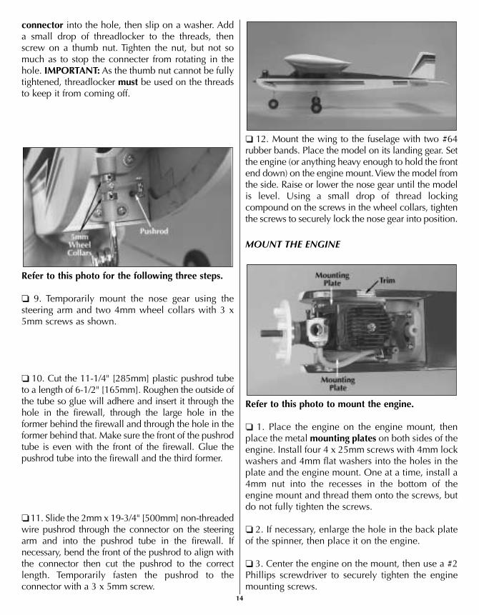
connector into the hole, then slip on a washer. Adda small drop of threadlocker to the threads, thenscrew on a thumb nut. Tighten the nut, but not somuch as to stop the connecter from rotating in thehole. IMPORTANT: As the thumb nut cannot be fullytightened, threadlocker must be used on the threadsto keep it from coming off.
Refer to this photo for the following three steps.
❏ 9. Temporarily mount the nose gear using thesteering arm and two 4mm wheel collars with 3 x5mm screws as shown.
❏ 10. Cut the 11-1/4" [285mm] plastic pushrod tubeto a length of 6-1/2" [165mm]. Roughen the outside ofthe tube so glue will adhere and insert it through thehole in the firewall, through the large hole in theformer behind the firewall and through the hole in theformer behind that. Make sure the front of the pushrodtube is even with the front of the firewall. Glue thepushrod tube into the firewall and the third former.
❏ 11. Slide the 2mm x 19-3/4" [500mm] non-threadedwire pushrod through the connector on the steeringarm and into the pushrod tube in the firewall. Ifnecessary, bend the front of the pushrod to align withthe connector then cut the pushrod to the correctlength. Temporarily fasten the pushrod to theconnector with a 3 x 5mm screw.
❏ 12. Mount the wing to the fuselage with two #64rubber bands. Place the model on its landing gear. Setthe engine (or anything heavy enough to hold the frontend down) on the engine mount. View the model fromthe side. Raise or lower the nose gear until the modelis level. Using a small drop of thread lockingcompound on the screws in the wheel collars, tightenthe screws to securely lock the nose gear into position.
MOUNT THE ENGINE
Refer to this photo to mount the engine.
❏ 1. Place the engine on the engine mount, thenplace the metal mounting plates on both sides of theengine. Install four 4 x 25mm screws with 4mm lockwashers and 4mm flat washers into the holes in theplate and the engine mount. One at a time, install a4mm nut into the recesses in the bottom of theengine mount and thread them onto the screws, butdo not fully tighten the screws.
❏ 2. If necessary, enlarge the hole in the back plateof the spinner, then place it on the engine.
❏ 3. Center the engine on the mount, then use a #2Phillips screwdriver to securely tighten the enginemounting screws.
14

❏ 4. Test fit the muffler to the engine. If necessary,use a Dremel tool with a drum sander or a hobbyknife to trim the fuselage to accommodate themuffler. (If using a Dremel, stuff the engine exhaustand the opening in the carburetor with a piece of apaper towel to keep dust from entering.) Coat theexposed wood with epoxy or medium CA.
INSTALL THE FUEL TANK
Refer to the photo and the sketch while installing the fuel tank.
❏ 1. Pull the stopper out of the fuel tank and shakeout the contents. Note that there are three holes inthe back of the stopper, but two holes in the front.The fuel system on this model requires only twolines (a fuel pickup line and the pressure line), so thethird hole in the stopper will not be used.
❏ 2. Insert the long aluminum tube into the metalfront plate and push it through the hole in the rightside of the stopper until approximately 1/2" [13mm]of the tube protrudes from the front. Insert the shortaluminum tube through the other hole.
❏ 3. Tighten the screw just until the metal back platecontacts the back of the stopper. Bend the longaluminum tube upward as shown in the photo so itwill be near the top of the tank when the assemblyis installed in the tank.
❏ 4. Fit the fuel line to the short aluminum tube. Cutthe fuel line to the correct length so that when thefuel line weight (“clunk”) is installed, it will be near,but not contacting the back of the tank. Otherwise,the line may become stuck above the fuel leveldiscontinuing fuel flow.
❏ 5. Note that the tube in the right side of the tank is thepressure line that will be connected to the muffler andthe tube in the left side of the tank is the fuel tube whichwill be connected to the carburetor. Install the stopperand fuel line assembly into the tank. Make certain theclunk is not contacting the back of the tank, then tightenthe screw to expand the stopper, thus sealing the tank –approximately five or six full turns should be adequate.
❏ 6. Install the fuel tank into the fuselage with theneck of the tank through the hole in the firewall. Cut3-1/8" [80mm] from one of the 1/4" x 1/2" x 10" [6 x 12 x 255mm] balsa sticks. Trim the 3-1/8"[80mm] piece as necessary to fit between the backof the tank and the former to secure the fuel tank.
MOUNT THE AILERON SERVO
❏ 1. Cut a small hole in the bottom of the wing forthe servo wire. Cut the covering from the wing forthe 1/8" [3.2mm] plywood aileron servo tray.
Pressure Line(to muffler)
Fuel Pickup Line(to carburetor)
"Clunk"
SiliconeFuel Line
Firewall
AluminumTubes
15

Refer to this photo while mounting the aileron servo.
❏ 2. Use epoxy to glue the aileron servo tray to the wing.
❏ 3. Drill 1/16" holes through the servo tray formounting the servo. Run the servo screws in and outof the holes a few times to make some threads in thewood. Add a few drops of thin CA to the holes andallow to fully harden. Mount the servo in the wingusing the screws that came with the servo.
❏ 4. Make a two-arm servo arm from a four-armservo arm by cutting two of the arms off. Mount theservo arm to the servo.
❏ 5. Screw a nylon clevis twenty-five full turns ontoa 2mm x 9-7/8" [250mm] pushrod. Make anotherpushrod the same way. Screw the nylon torque rodhorns twelve full turns onto the aileron torque rods.
❏ 6. Connect one of the clevises on the pushrod toone of the torque rod horns. Make a 90-degree bendin the pushrod so that when connected to the servoarm, the aileron will be centered. Fit the pushrod inthe second from the outer hole in the servo arm,then secure it with a nylon pushrod keeper. Cut thepushrod 1/16" [2mm] from the keeper as shown inthe sketch. Note: It may be necessary to enlarge theholes in the servo arm to fit the pushrod. If so, use ahobby knife with a #11 blade to carefully enlargethe holes from both sides of the arm.
❏ 7. Connect the other pushrod to the servo arm andthe torque rod the same way.
❏ 8. Center the servo arm. Adjust the length of thepushrods by turning the clevises in or out until bothailerons are centered.
HOOK UP THE CONTROLS
Refer to this photo for the following three steps.
❏ 1. Make two one-arm servo arms from the armsthat came with the servos. Also make one two-armservo arm.
❏ 2. Install the arms on the servos, then test fit theservos in the 1/8" [3.2mm] plywood fuselage servotray as shown. If necessary, enlarge the openings inthe tray to accommodate your servos.
❏ 3. Drill 1/16" holes through the servo tray formounting the servos. Run the servo screws in andout of the holes a few times to make some threads inthe wood. Add a few drops of thin CA to the holesto harden the threads. After the CA has fullyhardened, mount the servos in the tray.
❏ 4. Refer to the photo at step 6. Use epoxy tosecurely glue the servo tray in the fuselage. Cut theelevator and rudder pushrod tubes so they “end”approximately 1/8" [3mm] ahead of the former onthe aft end of the servo tray.
Keeper
Pushrod WireServoArm
Keeper
16

❏ 5. Screw a clevis twenty-five full turns onto a 2-56 x 36" [915mm] pushrod. Connect the clevis tothe second-from-the-outer hole of a control horn.Make another pushrod assembly the same way.
❏ 6. Slide the pushrods into the pushrod tubes in thefuselage. Position the control horn on the rudder asshown in the photo and sketch. Use the control hornas a guide to drill two 5/64" [2mm] (or 3/32"[2.4mm]) holes through the rudder for the mountingscrews. Mount the control horn to the rudder withtwo 2 x 16mm Phillips-head screws and the plasticmounting plate.
❏ 7. Mount the elevator control horn to the elevatorwith two 2 x 20mm Phillips-head screws.
❏ 8. Carefully enlarge the holes in the elevator andrudder servo arms with a hobby knife and a #11 bladeor a 5/64" [2mm] drill.
Refer to this photo while connecting the pushrods to the servos.
❏ 9. Make a 90-degree bend in the elevator pushrodso the elevator will be centered when the pushrod isconnected to the servo arm. This is most easily doneby disconnecting the pushrod from the elevator,rotating the pushrod 90-degrees, then making thebend to the side. The clevis on the back of thepushrod will now have to be turned 90-degrees theother way. Take the servo arm off the elevator servosand fit the pushrod in the third hole out. Install thepushrod keeper, then cut the wire so 1/16" [2mm]protrudes. Reinstall the servo arm and clevis.
❏ 10. Connect the rudder and nose wheel pushrodthe same way. A few bends will have to be made inthe nose wheel pushrod to align it with the servo arm.
❏ 11. Use the remaining 13-1/2" [340mm] plasticpushrod tube and the 2mm x 27" [685mm] threaded
The Holes in theControl HornAlign with the
Pivot Point
ControlHorn
MountingPlate
PivotPoint
17
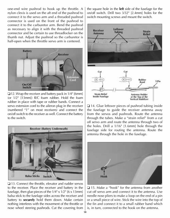
one-end wire pushrod to hook up the throttle. Anylon clevis is used on the aft end of the pushrod toconnect it to the servo arm and a threaded pushrodconnector is used on the front of the pushrod toconnect it to the carburetor arm. Bend the pushrodas necessary to align it with the threaded pushrodconnector and be certain to use threadlocker on thethumb nut. Adjust the pushrod so the carburetor ishalf-open when the throttle servo arm is centered.
❏ 12. Wrap the receiver and battery pack in 1/4" [6mm](or 1/2" [13mm]) R/C foam rubber. Hold the foamrubber in place with tape or rubber bands. Connect aservo extension cord to the aileron plug in the receiver(numbered “1” on most receivers) and connect theon/off switch to the receiver as well. Connect the batteryto the switch.
❏ 13. Connect the throttle, elevator and rudder servosto the receiver. Place the receiver and battery in thefuselage, then glue pieces of the 1/4" x 1/2" [6 x 13mm]balsa stick to the fuselage sides across the receiver andbattery to securely hold them down. Make certainnothing interferes with the movement of the throttle ornose wheel steering pushrods. Cut the covering from
the square hole in the left side of the fuselage for theon/off switch. Drill two 3/32" [2.4mm] holes for theswitch mounting screws and mount the switch.
❏ 14. Glue leftover pieces of pushrod tubing insidethe fuselage to guide the receiver antenna awayfrom the servos and pushrods. Route the antennathrough the tubes. Make a “strain relief” from a cutoff servo arm and route the antenna through two ofthe holes. Drill a 1/16" [1.6mm] hole through thefuselage side for routing the antenna. Route theantenna through the hole in the fuselage.
❏ 15. Make a “hook” for the antenna from anothercut off servo arm and connect it to the antenna. Useneedle nose pliers to make a loop on the end of a pinor a small piece of wire. Stick the wire into the top ofthe fin and connect it to a small rubber band whichis, in turn, connected to the hook on the antenna.
18
MOUNT THE MUFFLER, PROP AND FUEL LINES
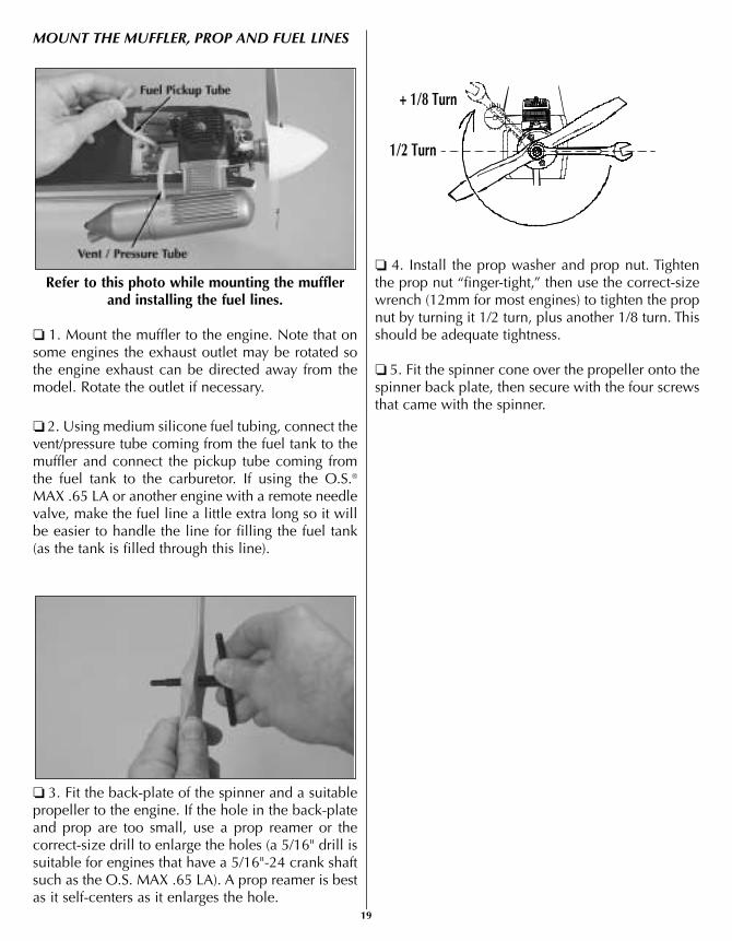
Refer to this photo while mounting the muffler and installing the fuel lines.
❏ 1. Mount the muffler to the engine. Note that onsome engines the exhaust outlet may be rotated sothe engine exhaust can be directed away from themodel. Rotate the outlet if necessary.
❏ 2. Using medium silicone fuel tubing, connect thevent/pressure tube coming from the fuel tank to themuffler and connect the pickup tube coming fromthe fuel tank to the carburetor. If using the O.S.®
MAX .65 LA or another engine with a remote needlevalve, make the fuel line a little extra long so it willbe easier to handle the line for filling the fuel tank(as the tank is filled through this line).
❏ 3. Fit the back-plate of the spinner and a suitablepropeller to the engine. If the hole in the back-plateand prop are too small, use a prop reamer or thecorrect-size drill to enlarge the holes (a 5/16" drill issuitable for engines that have a 5/16"-24 crank shaftsuch as the O.S. MAX .65 LA). A prop reamer is bestas it self-centers as it enlarges the hole.
❏ 4. Install the prop washer and prop nut. Tightenthe prop nut “finger-tight,” then use the correct-sizewrench (12mm for most engines) to tighten the propnut by turning it 1/2 turn, plus another 1/8 turn. Thisshould be adequate tightness.
❏ 5. Fit the spinner cone over the propeller onto thespinner back plate, then secure with the four screwsthat came with the spinner.
+ 1/8 Turn
1/2 Turn
19

BALANCE THE MODEL (C.G.)
At this time the model must be in “ready-to-fly”condition with all components installed includingthe complete radio system, landing gear, engine,prop and spinner. The model is to be balanced withthe fuel tank empty.
❏ 1. If using a Great Planes® C.G. Machine™ tobalance the model, set the rulers to 3" [76mm]. Ifyou do not have a Great Planes C.G. Machine, usea felt-tip pen or 1/16" to 1/8" [1.5 to 3mm] tape toaccurately mark the C.G. 3" [76mm] from theleading edge on the bottom of the wing.
❏ 2. Mount the wing to the fuselage with at least four#64 rubber bands. If using a C.G. Machine, place themodel on the machine. If not using a C.G. Machine, usethe tip of your middle fingers on both hands to lift themodel by the wing on both sides of the fuselage at thebalance point you marked on the bottom of the wing.
❏ 3. If the fuselage is level when lifting the model theC.G. is correct. If the nose drops the model is nose-heavy and will require weight on the tail to balance.
This is where the model should balance for the firstflights. Later, you may wish to experiment by shiftingthe C.G. up to 1/2" [13mm] forward or 1/2" [13mm]back to change the flying characteristics. Moving theC.G. forward will increase stability, but will decreasethe model's aerobatic capabilities by decreasingmaneuverability. Moving the C.G. aft will have theopposite effect. In any case, as long as the model isbalanced within the recommended range it will notdisplay any bad tendencies. Do not at any timebalance the model outside the recommended range.
More than any other factor, the C.G. (center ofgravity, also referred to as the balance point) canhave the greatest effect on how a model flies andmay determine whether or not the first flight will besuccessful. If the plane is nose heavy it could bedifficult to takeoff and land and lose some of its self-recovery capabilities. If the plane is tail heavy thecontrols may be too sensitive, making the modeloverreact to control inputs. If you value this modeland wish to enjoy it for many flights, DO NOTOVERLOOK THIS IMPORTANT PROCEDURE. Amodel that is not properly balanced will be unstableand possibly unflyable.
Prepare the Model for Flying
20

If however, the tail drops, the model is tail heavy andthe model will require weight on the nose to balance.Determine how much weight will be required bytemporarily placing varying amounts of Great Planes“stick-on” lead weight (GPMQ4485) over the nose ortail until the correct amount is determined. Ourprototypes required about 2-1/2 oz. [70g] of lead onthe tail to balance so it is likely that your model willrequire some amount of tail weight as well. Don't bealarmed if your model requires more or less tailweight than ours did. There are several factors thatcan determine the amount of weight required such asthe exact position and weight of the engine, densityof wood the model was constructed from, etc.
❏ 4. Attach weight to the model where required. If noseweight is required it should be adhered to the firewall or
the inside of one of the fuselage sides in front of thefirewall. Due to the likelihood of fuel coming intocontact with the double-sided foam tape that holds thelead in place, the best way to secure nose weight is toscrape off the foam tape and permanently glue the leadinto place with epoxy. If tail weight is required, do notsimply adhere the lead to the covering. Instead, use apin to poke several holes in the covering over the leftside of the fuselage (opposite the engine exhaust) underthe stabilizer. Add several drops of thin CA to the areato thoroughly bond the covering to the wood. Now thelead may be stuck to the fuselage. Be certain any weightstuck to the tail does not interfere with the pushrods.
Note: An optional way to add nose weight, if required,is to use a “spinner weight” (GPMQ4645 for 1 oz.[29g] weight, or GPMQ4646 for 2 oz. [57g] weight).Spinner weights are used in place of the prop washer.
❏ 5. IMPORTANT: If you found it necessary to addany weight, recheck the C.G. after the weight hasbeen added.
CENTER THE SERVOS
❏ 1. Set the wing upside-down on a small cardboardbox or a stand and place it next to the fuselage.Connect the aileron servo wire from the wing to theservo extension coming from the receiver.
❏ 2. Take the servo arms off all the servos.
❏ 3. Center all the trim levers on the transmitter.Turn on the transmitter, then the receiver. (The ideais to never have the receiver on by itself. Whenturning off the system, turn off the receiver first, thenthe transmitter.) This will “center” the servos.Reinstall the servo arms on all the servos followedby the screws that hold on the arms.
21

CHECK THE CONTROL DIRECTIONS
Move the control sticks on the transmitter as shownto be certain the controls on the airplane respond inthe correct direction. If any of the controls move thewrong way, use the servo reversing switches on thetransmitter to make the controls respond correctly. Ifnecessary, refer to the instructions in the instructionmanual that came with your radio to identify andoperate the reversing switches.
CENTER THE CONTROL SURFACES
Even though the trim levers on the transmitter maybe used to center the control surfaces, you shouldstart out with the trims centered.
Do the elevator first.
❏ 1. With the transmitter and receiver on, view theelevator and stab from the end. If the elevator is notcentered, disconnect the clevis from the controlhorn on the elevator. Holding the end of the pushrodwith pliers, screw or unscrew the clevis as necessaryuntil the elevator will be centered whenreconnected to the pushrod. Note: Be sure not tounscrew the clevis too far. It must remain securelyfastened to the end of the pushrod.
❏ 2. Center the rudder and both ailerons the same way.
❏ 3. Now that the rudder is centered, center thenose wheel by adjusting the pushrod in the threadedconnector on the steering arm. Roll the fuselagealong a flat surface (such as your garage, basementor kitchen floor) to make certain it rolls straight. Thisshould be done with the transmitter and receiver on.Make adjustments if necessary. Add a small drop ofthreadlocker to the screw and securely tighten tolock the pushrod into position.
Stabilizer Elevator
Elevator NOT Centered With Stab
Elevator Centered With Stab
Note that pulling the elevator stick back movesthe elevator up (which, in flight, pushes the taildown, thus raising the nose of the plane to climb).The best way to keep this in mind is to think interms of a pilot in an actual airplane. He pulls thecontrol stick back to raise the nose of the plane.
Move Stick Right
Rudder (and Nosewheel)Move Right
Move Stick Right
Right Aileron Goes Up
Left Aileron Goes Down
Pull Stick Back (Down)
Elevator Moves Up
22

❏ 4. Install a silicone retainer on all the clevises(elevator, rudder, ailerons, throttle). If you'vemisplaced the retainers that came with the model,use 1/4" [6mm] pieces cut from leftover fuel tubing.
ADJUST THE THROTTLE
The throttle is to be set up so that, when the throttlestick is all the way down and the throttle trim leveris all the way up, the carburetor will be slightly open(so the engine will idle at a low RPM). When theengine is to be shut off, the trim lever is moveddown to close the carburetor the rest of the way.
❏ 1. With the transmitter and receiver on, move the throttle trim lever and the throttle stick all theway down.
❏ 2. Observe the opening in the carburetor. If thecarburetor is fully closed, proceed to step 3. If the
carburetor is not fully closed, adjust the pushrod atthe connector on the carburetor arm or at the clevison the servo arm until the carburetor is closed.
❏ 3. Move the throttle trim lever all the way up, butleave the throttle stick all the way down. Now thecarburetor should be partially open (about 1/32" to1/16" [1 to 1.5mm]).
❏ 4. Move the throttle stick all the way up. Thecarburetor should be fully open. If the carb is not fullyopen, the pushrod travel may have to be increased.This is done by moving the clevis further out on theservo arm (or by moving the pushrod connectorcloser in on the carburetor arm). Adjust the pushrodas necessary to achieve the correct setup.
SET THE CONTROL THROWS
The control throws are a measure of how far theflight controls (elevator, ailerons, rudder) move upand down (or from side to side). If the controls movetoo much, the plane will respond too quickly and bedifficult to control. If the controls do not moveenough, there will not be enough control to fly orland the model. Due to the great effect the controlthrows have on the way a model flies, the controlthrows must be set according to the measurementsprovided in this manual.
Carburetor Fully Open
Trim Lever Up
ThrottleStick Down
Carburetor Partially OpenCarburetor Fully Closed
Trim Lever Down
ThrottleStick Down
23
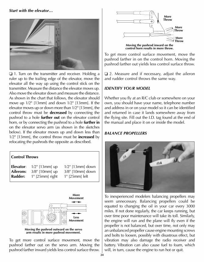
Start with the elevator…
❏ 1. Turn on the transmitter and receiver. Holding aruler up to the trailing edge of the elevator, move theelevator all the way up using the control stick on thetransmitter. Measure the distance the elevator moves up.Also move the elevator down and measure the distance.As shown in the chart that follows, the elevator shouldmove up 1/2" [13mm] and down 1/2" [13mm]. If theelevator moves up or down more than 1/2" [13mm], thecontrol throw must be decreased by connecting thepushrod to a hole further out on the elevator controlhorn, or by connecting the pushrod to a hole further inon the elevator servo arm (as shown in the sketchesbelow). If the elevator moves up and down less than1/2" [13mm], the control throw must be increased byrelocating the pushrods the opposite as described.
To get more control surface movement, move thepushrod farther out on the servo arm. Moving thepushrod farther inward yields less control surface throw.
To get more control surface movement, move thepushrod farther in on the control horn. Moving thepushrod farther out yields less control surface throw.
❏ 2. Measure and if necessary, adjust the aileronand rudder control throws the same way.
IDENTIFY YOUR MODEL
Whether you fly at an R/C club or somewhere on yourown, you should have your name, telephone numberand address in or on your model so it can be identifiedand returned in case it lands somewhere away fromthe flying site. Fill out the I.D. tag found at the end ofthe manual and place it on or inside the model.
BALANCE PROPELLERS
To inexperienced modelers balancing propellers mayseem unnecessary. Balancing propellers could beequated to changing the oil in your car every 3000miles. If not done regularly, the car keeps running, butover time poor maintenance will take its toll. Similarly,the engine will run and the plane will fly even if thepropeller is not balanced, but over time, not only mayan unbalanced propeller cause engine mounting screwsand bolts to loosen, possibly with disastrous effect, butvibration may also damage the radio receiver andbattery. Vibration can also cause fuel to foam, whichwill, in turn, cause the engine to run hot or quit.
MoreThrow
MoreThrow
Moving the pushrod inward on thecontrol horn results in more throw.
MoreThrow
MoreMovement
LessMovement
Moving the pushrod outward on the servoarm results in more pushrod movement.
Control Throws
Elevator: 1/2" [13mm] up 1/2" [13mm] downAilerons: 3/8" [10mm] up 3/8" [10mm] downRudder: 1" [25mm] right 1" [25mm] left
24

If you do not yet have a propeller balancer, ask yourflight instructor or another club member if they willhelp you balance your propellers. We use a Top FlitePrecision Magnetic Prop Balancer™ (TOPQ5700) inthe workshop and keep a Great Planes FingertipProp Balancer (GPMQ5000) in our flight box.
CHARGE THE BATTERIES
If you haven't already done so, refer to theinstruction manual that came with the radio andcharge the batteries in the plane and in thetransmitter overnight the night before you go flying.
GATHER YOUR TOOLS
In addition to the engine starting equipmentmentioned near the beginning of the manual, youshould start a collection of tools that may be requiredfor adjustments and maintenance at the flying field.Following is a list of the most suggested items…
Tools:❏ #1 Phillips screwdriver❏ #2 Phillips screwdriver❏ 5/16" (or 8mm) socket wrench (for glow plug)❏ 1.5mm hex wrench (for wheel collars)❏ 12mm wrench or crescent wrench (for propeller nut)❏ Pliers❏ Hobby knife
Spare parts:❏ Suitable propellers❏ Glow plug❏ #64 rubber bands (stored in container with talcumpowder or kitty litter)
Flight preparation is to be done at the flying field.
Be certain your flight instructor performs thesefollowing checks with you.
CHECK THE CONTROLS
1. Get the frequency clip from the frequency controlboard at your flying site.
2. Mount the wing to the fuselage with #64 rubberbands. Twelve to fourteen rubber bands aresuggested. Be certain the final two are “crisscrossed,”thus ensuring that the others remain secure.
IMPORTANT:Your radio control system transmits asignal on a certain frequency. Be certain you knowwhat the frequency is. This is expressed as a two-digit number (42, 56, etc.) and can be found on thecontainer the radio system came in and is alsolocated on the transmitter and receiver. There aremany different frequencies, but there is still achance that someone else at the flying field may beon the same frequency as you. If you turn on yourtransmitter while that person is flying, a crash willresult. NEVER turn on your transmitter until youhave permission from your instructor and until youhave possession of the frequency clip used forfrequency control at the flying site.
Flight PreparationCHECKLIST
Now it's time to do a final check before taking themodel to the field. Take the time to do thesechecks to make certain your model is ready to fly.
❏ 1. Make certain the screws on all the wheelcollars that hold the wheels on are secure.Threadlocker is recommended on the screws.❏ 2. Check to see that the screws that hold theservo arms to the servos are present and secure.❏ 3. Be certain the silicone retainers on all thenylon clevises are in position.❏ 4. Make certain the throttle, elevator, rudderand ailerons respond in the correct direction.❏ 5. Make certain the propeller and propellerspinner are secure.❏ 6. Balance the model according to the instructions.❏ 7. Fill-out and place the I.D. card inside the model.❏ 8. Balance the propeller and spare propellers.
25

3. Turn on the transmitter and receiver. One at atime, operate each control on the airplane using thetransmitter. Make certain each control is respondingcorrectly. This must be done before every flight.There are several types of malfunctions that can bediscovered by performing this elementary task, thussaving your model!
RANGE CHECK THE RADIO
A range check must be performed before the firstflight of a new model. It is not necessary to do arange check before every flight (but is not a bad ideato perform a range check before the first flight ofeach day). A range check is the final opportunity toreveal any radio malfunctions and to be certain thesystem has adequate operational range.
1. BE CERTAIN you have the frequency clip.
2. Turn on the transmitter and receiver. Leave thetransmitter antenna all the way down. Walk away fromthe model while simultaneously operating the controls.Have an assistant stand by the model and tell you whatthe controls are doing to confirm that they operatecorrectly. You should be able to walk approximately100 feet from the model and still have control withoutany “glitching” or inadvertent servo operation.
3. If everything operates correctly, return to the modeland start the engine. Perform the range check withyour assistant holding the plane with the enginerunning at various speeds. If the servos chatter ormove inadvertently, there may be a problem. Do notfly the plane! With the assistance of your instructor,look for loose servo connections or binding pushrods.Also be certain you are the only one on yourfrequency and that the battery has been fully charged.
GROUND CHECK
If the engine is new, follow the engine manufacturer'sinstructions to break-in the engine. After break-in,confirm that the engine idles reliably, transitionssmoothly and rapidly to full power and maintains fullpower—indefinitely. After you run the engine on themodel, inspect the model closely to make sure allscrews remained tight, the hinges are secure, the propis secure and all pushrods and connectors are secure.
Keep all engine fuel in a safe place, away from highheat, sparks or flames, as fuel is very flammable. Donot smoke near the engine or fuel; and rememberthat engine exhaust gives off a great deal of deadlycarbon monoxide. Therefore do not run the enginein a closed room or garage.
Get help from an experienced pilot when learning tooperate engines.
Use safety glasses when starting or running engines.
Do not run the engine in an area of loose gravel orsand; the propeller may throw such material in yourface or eyes.
Keep your face and body as well as all spectatorsaway from the plane of rotation of the propeller asyou start and run the engine.
Keep these items away from the prop: looseclothing, shirt sleeves, ties, scarfs, long hair or looseobjects such as pencils or screwdrivers that may fallout of shirt or jacket pockets into the prop.
Use a “chicken stick” or electric starter to start theengine. Do not use your fingers to flip the propeller.Make certain the glow plug clip or connector issecure so that it will not pop off or otherwise get intothe running propeller.
Make all engine adjustments from behind therotating propeller.
The engine gets hot! Do not touch it during or rightafter operation. Make sure fuel lines are in goodcondition so fuel will not leak onto a hot engine,causing a fire.
To stop a glow engine, cut off the fuel supply by closingoff the fuel line or following the engine manufacturer'srecommendations. Do not use hands, fingers or anyother body part to try to stop the engine. Do not throwanything into the propeller of a running engine.
Failure to follow these safety precautions mayresult in severe injury to yourself and others.
Engine Safety Precautions
26

Read and abide by the following Academy of ModelAeronautics Official Safety Code:
GENERAL1. I will not fly my model aircraft in sanctionedevents, air shows, or model flying demonstrationsuntil it has been proven to be airworthy by havingbeen previously successfully flight tested.
2. I will not fly my model aircraft higher thanapproximately 400 feet within 3 miles of an airportwithout notifying the airport operator. I will giveright of way to and avoid flying in the proximity offull scale aircraft. Where necessary an observer shallbe used to supervise flying to avoid having modelsfly in the proximity of full scale aircraft.
3. Where established, I will abide by the safetyrules for the flying site I use and I will not willfullyand deliberately fly my models in a careless,reckless and/or dangerous manner.
7. I will not fly my model unless it is identifiedwith my name and address or AMA number, on or inthe model.
9. I will not operate models with pyrotechnics (anydevice that explodes, burns, or propels a projectileof any kind).
RADIO CONTROL1. I will have completed a successful radioequipment ground check before the first flight of anew or repaired model.
2. I will not fly my model aircraft in the presenceof spectators until I become a qualified flier, unlessassisted by an experienced helper.
3. I will perform my initial turn after takeoff away fromthe pit or spectator areas and I will not thereafter fly overpit or spectator areas, unless beyond my control.
4. I will operate my model using only radio controlfrequencies currently allowed by the FederalCommunications Commission...
End of AMA Safety Code
These flying instructions are not an endorsement forlearning to fly on your own, but are printed so youcan know what to expect and what to concentrate onwhile learning under the tutelage of your instructor.Further, these flight instructions may be referencedonce you finally do begin flying on your own.
CAUTION (THIS APPLIES TO ALL R/C AIRPLANES):If, while flying, you notice an alarming or unusualsound such as a low-pitched “buzz,” this mayindicate control surface flutter. Flutter occurs when acontrol surface (such as an aileron or elevator) or aflying surface (such as a wing or stab) rapidly vibratesup and down (thus causing the noise). In extremecases, if not detected immediately, flutter can actuallycause the control surface to detach or the flyingsurface to fail, thus causing loss of control followedby an impending crash. The best thing to do whenflutter is detected is to slow the model immediatelyby reducing power, then land as soon as safelypossible. Identify which surface fluttered (so theproblem may be resolved) by checking all the servogrommets for deterioration or signs of vibration.Make certain all pushrod linkages are secure and freeof play. If it fluttered once, under similarcircumstances it will probably flutter again unless theproblem is fixed. Some things which can cause flutterare; Excessive hinge gap; Not mounting control hornssolidly; Poor fit of clevis pin in horn; Side-play of wirepushrods caused by large bends; Excessive free playin servo gears; Insecure servo mounting; and one ofthe most prevalent causes of flutter; Flying an over-powered model at excessive speeds.
IMPORTANT: If you do insist on flying on your own,you must be aware of your proximity to R/C clubsites. If there is an R/C site within six miles of whereyou are flying and if you are operating your modelon the same frequency as somebody else, there is astrong possibility that one or both models will crashdue to radio interference. There is great potential foran out-of-control model to cause property damageand/or severe personal injury. We strongly urge youto fly at a R/C club site where frequency control isin effect so you can be confident you will be theonly one flying on your channel.
FlyingAMA Safety Code (excerpt)
27

TAXIINGRemember, it is assumed that your instructor isoperating the model for you.
Before the model is ready for takeoff, it must first be setup to roll straight down the runway. With the enginerunning at a low idle, place the plane on the runwayand, if your flying field permits, stand behind the model.Advance the throttle just enough to allow the model toroll. If the model does not roll straight down the runway,shut the engine off and adjust the nose gear pushrod asnecessary. Do not use the rudder trim to correct the nosewheel because this will also affect the rudder. Note:Crosswinds may affect the direction the model rolls, sothis test should be done in calm conditions, or with themodel facing directly into the wind.
TAKEOFFIf possible, takeoff directly into the wind. If you areexperienced, taking off in a crosswind is permissible (andsometimes necessary—depending upon the prevailingwind conditions and runway heading). Taking off into thewind will help the model roll on a straight path and alsoreduces ground speed for takeoff. Taxi the model onto therunway or have an assistant carry it out and set it downpointing into the wind down the runway. When ready,gradually advance the throttle while simultaneously usingthe left stick (rudder/nose wheel) to steer the model. Gainas much speed as the runway and flying site will practicallyallow before gently applying up elevator, lifting the modelinto the air. Be ready to make immediate corrections withthe ailerons to keep the wings level and be smooth on theelevator stick, allowing the model to establish a gentleclimb to a safe altitude before making the first turn (awayfrom yourself). Do not “yank” back the elevator stickforcing the plane into too steep of a climb which couldcause the model to quit flying and stall.
FLIGHT Once airborne, maintain a steady climb and make theinitial turn away from the runway. When at a comfortable,safe altitude throttle back to slow the model, thus givingyou time to think and react. The Hobbistar .60 MKIIIshould fly well at half or even slightly less than half-throttle.Adjust the trims so the plane flies straight and level at your“cruise” throttle setting. After flying around for a while andwhile still at a safe altitude with plenty of fuel, practiceslow flight and execute practice landing approaches byreducing the throttle further to see how the model handleswhen coming in to land. Add power to see how the modelclimbs as well. Continue to fly around while learning howthe model responds. Mind your fuel level, but use this firstflight to become familiar with the model before landing.
LANDINGWhen ready to land, pull back the throttle stick fullywhile flying downwind just before making the 180-degree turn toward the runway. Allow the nose of themodel to pitch downward to gradually bleed offaltitude. Continue to lose altitude, but maintainairspeed by keeping the nose down while turning.Apply up elevator to level the plane when it reaches theend of the runway and is about five to ten feet off theground. If the model is too far away, carefully add asmall amount of power to fly the model closer. If goingtoo fast, smoothly advance the throttle and allow themodel to gain airspeed, then apply elevator to climb-out and go around to make another attempt. Whenfinally ready to touch down, continue to apply upelevator, but not so much that the airplane will climb.Continue to apply up elevator while the plane descendsuntil it gently touches down.
After you have landed and shut the engine off, adjustthe pushrods on the ailerons, elevator and rudder asnecessary so the trim levers on the transmitter may bereturned to center (this will not be required on any ofthe controls that did not need trim adjustments).
1. After flying for the day, don't forget to use your fuelpump to drain excess fuel from the tank.
2. Do not reuse torn or oily rubber bands. Purchase sparerubber bands (HCAQ2020, 1/4 lb box). After flying, oilyrubber bands should be stored in a container with talcumpowder or kitty litter. This will absorb oil and keep therubber bands fresh for the next flying session.
3. After each day's flying, use spray cleaner and papertowels to thoroughly clean the model.
Maintenance Tips


![INSTRUCTION MANUAL - Hobbicomanuals.hobbico.com/gpm/gpma1580-manual-v1_1.pdf · INSTRUCTION MANUAL Wingspan: 35 in [890mm] Wing Area: 600 in2 [38.7dm2] Weight: 34.2 – 38.2 oz [970](https://img.pdfslide.net/doc/110x75/5c66983f09d3f20f218c7d2f/instruction-manual-instruction-manual-wingspan-35-in-890mm-wing-area-600.jpg)