Embed Size (px)
DESCRIPTION
Cargo floor CF500
Citation preview
2012 Cargo Floor B.V. Coevorden, Holland
Versie 01/11-01-2012 www.cargofloor.com [email protected]
Cargo Floor B.V. P.O. Box 271 NL-7740 AG Coevorden Phone: +31-(0)524- 593900 Fax: +31-(0)524- 593999
CARGO FLOOR®
NL Inbouwinstructies GB Assembly instructions
D Einbauanleitung
CF500 SL-2 21-112 CF100 SL-2 21-112

2012 Cargo Floor B.V. Coevorden, Holland
Versie 01/11-01-2012 www.cargofloor.com [email protected]
Cargo Floor B.V. P.O. Box 271 NL-7740 AG Coevorden Phone: +31-(0)524- 593900 Fax: +31-(0)524- 593999
Blz. 2
Coevorden, Holland © 2012 Cargo Floor B.V.
NL Niets aan deze uitgave mag worden verveelvoudigd en/of openbaar gemaakt door middel van druk, fotokopie, microfilm, of op welke andere wijze dan ook zonder voorafgaande schriftelijke toestemming van de uitgever.
GB No part of this publication may be reproduced, stored in a retrieval system, or transmitted, in any form or by
any means, electronic, photocopying, recording or otherwise, without the prior permission of Cargo Floor B.V.
D Kein Teil dieser Veröffentlichung darf ohne die vorherige Genehmigung von Cargo Floor B.V.
vervielfältigt, in einem Datensystem gespeichert oder übertragen werden. Dies gilt für alle Techniken und Medien, sei es in elektronischer Form, durch Fotokopie, durch Aufnahme oder in anderweitiger Weise.
2012 Cargo Floor B.V. Coevorden, Holland
Versie 01/11-01-2012 www.cargofloor.com [email protected]
Cargo Floor B.V. P.O. Box 271 NL-7740 AG Coevorden Phone: +31-(0)524- 593900 Fax: +31-(0)524- 593999
Blz. 3
NL INLEIDING
De in dit boek opgenomen inbouwinstructie dient ervoor het door u aangeschafte Cargo Floor systeem op een technisch verantwoorde wijze te monteren. Hierbij is getracht, met behulp van tekeningen en tekst, de instructie zo eenvoudig en doeltreffend mogelijk te houden. Teneinde de grote duurzaamheid en bedrijfszekerheid van dit revolutionaire laad- en lossysteem te bewerkstellingen, wordt u geacht zich volledig te houden aan de hierin opgenomen inbouwmethode en de kwaliteit en de maatvoering van de te gebruiken materialen. Hierbij zei vermeld, dat garantie alleen kan gelden wanneer het Cargo Floor systeem conform deze inbouwinstructie wordt ingebouwd. Op onze internetsite: www.cargofloor.com vindt u de laatste beschikbare versie.
GB INTRODUCTION
The assembly instructions outlined in this book will enable you to assemble the Cargo Floor system you have purchased correctly. Every effort has been made, by means of diagrams and text, to give clear and simple instructions. To ensure the durability and reliability of this revolutionary loading and unloading system, it is important that you follow the assembly instructions as outlined in this book completely, and use quality materials in accordance with the specifications. Please note that the guarantee is only valid if the Cargo Floor system has been assembled in accordance with these assembly instructions. The latest available version can be found on our internet site: www.cargofloor.com
D EINLEITUNG
Die in dieses Buch aufgenommene Einbauanleitung dient dazu, das von Ihnen erworbene Cargo Floor System fachgerecht und technisch richtig zu montieren. Hierbei haben wir uns bemüht, diese Anleitung durch den Einsatz von Zeichnungen und Text so einfach und zweckmäßig wie möglich zu gestalten. Um die lange Haltbarkeit und große Betriebssicherheit dieses hochmodernen Lade- und Entlade-Systems zu gewährleisten, sollten Sie sich in vollem Umfang an die hier dargestellte Einbaumethode sowie die Qualität und die Maße der zu verwendenden Materialien halten. In diesem Zusammenhang muss betont werden, dass die Garantiebestimmungen nur gelten, wenn das Cargo Floor System gemäß dieser Einbauanleitung installiert wird. Auf unserem Internetsite können Sie die letzte verfügbare Version finden, www.cargofloor.com.
2012 Cargo Floor B.V. Coevorden, Holland
Versie 01/11-01-2012 www.cargofloor.com [email protected]
Cargo Floor B.V. P.O. Box 271 NL-7740 AG Coevorden Phone: +31-(0)524- 593900 Fax: +31-(0)524- 593999
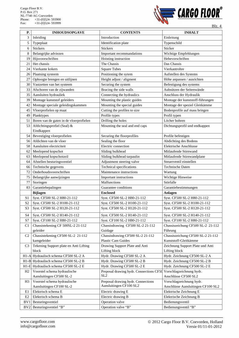
Blz. 4 P. INHOUDSOPGAVE CONTENTS INHALT
3 Inleiding Introduction Einleitung
5 Typeplaat Identification plate Typenschild
6 Stickers Stickers Sticker
8 Belangrijke adviezen Important recommandations Wichtige Empfehlungen
19 Hijsvoorschriften Hoisting instruction Hebevorschriften
21 Het chassis The Chassis Das Chassis
24 Vierkante kokers Square Tubes Vierkantrohre
26 Plaatsing systeem Positioning the sytem Aufstellen des Systems
27 Ophoogte brengen en uitlijnen Height adjust / aligment Höhe anpassen / ausrichten
30 Vastzetten van het systeem Securing the system Befestigung des systems
33 Afschoren van de zijwanden Bracing the side walls Aubsützen der Seitenwände
35 Aansluiten hydrauliek Connecting the hydraulics Anschluss der Hydraulik
39 Montage kunststof geleiders Mounting the plastic guides Montage der kunststoff-führungen
42 Montage speciale geleidingskammen Mounting the special guides Montage der speziel Gleitkämme
45 Vloerprofielen op maat Cutting the profiles to size Bodenprofile auf mass bringen
49 Planktypes Profile types Profil typen
51 Boren van de gaten in de vloerprofielen Drilling the holes Löcher bohren
53 Afdichtingsprofiel (Seal) & Eindkappen
Mounting the seal and end caps Dichtungsprofil und endkappen
54 Bevestiging vloerprofielen Securing the floorprofiles Profile befestigen
56 Afdichten van de vloer Sealing the floor Abdichting des Bodens
58 Aansluiten electriciteit Electric connection Elektrische Anschlusse
62 Meelopend kopschot Sliding bulkhead Mitlaufende Stirnwand
63 Meelopend kopschotzeil Sliding bulkhead tarpaulin Mitlaufende Stirnwandplane
64 Afstellen besturingsventiel Adjustment steering valve Steuerventil einstellen
66 Technische gegevens Technical specifications Technische Daten
72 Onderhoudsvoorschriften Maintenance instructions Wartung
75 Belangrijke aanwijzingen Important instructions Wichtige Hinweise
77 Storingen Malfunctions Störfalle
83 Garantiebepalingen Guarantee conditions Garantiebestimmungen
Bijlagen Enclosed Anlagen
S1 Syst. CF500 SL-2 H80-21-112 Syst. CF500 SL-2 H80-21-112 Syst. CF500 SL-2 H80-21-112
S2 Syst. CF500 SL-2 H100-21-112 Syst. CF500 SL-2 H100-21-112 Syst. CF500 SL-2 H100-21-112
S3 Syst. CF500 SL-2 H120-21-112 Syst. CF500 SL-2 H120-21-112 Syst. CF500 SL-2 H120-21-112
S4 Syst. CF500 SL-2 H140-21-112 Syst. CF500 SL-2 H140-21-112 Syst. CF500 SL-2 H140-21-112
S7 Syst. CF100 SL-2 H80-21-112 Syst. CF100 SL-2 H80-21-112 Syst. CF100 SL-2 H80-21-112
C1 Chassistekening CF 500SL-2 21-112 geleider
Chassisdrawing CF500 SL-2 21-112 Guidage
Chassiszeichung CF500 SL-2 21-112 Führung
C2 Chassistekening CF500 SL-2 21-112 kamgeleider
Chassisdrawing CF500 SL-2 21-112 Plastic Cam Guides
Chassiszeichung CF500 SL-2 21-112 Kunststoff-Gleitkämme
C3 Tekening Support plate en Anti Lifting block
Drawing Support Plate and Anti Lifting block
Zeichnung Support Plate und Anti Lifting block
H1-A Hydraulisch schema CF500 SL-2 A Hydr. Drawing CF500 SL-2 A Hydr. Zeichnung CF500 SL-2 A
H1-B Hydraulisch schema CF500 SL-2 B Hydr. Drawing CF500 SL-2 B Hydr. Zeichnung CF500 SL-2 B
H1-E Hydraulisch schema CF500 SL-2 E Hydr. Drawing CF500 SL-2 E Hydr. Zeichnung CF500 SL-2 E
H2 Voorstel schema hydraulische Aansluitingen CF500 SL-2
Preposal drawing hydr. Connections CF50SL2
Vorschlagzeichnung hydr. Anschlüsse CF500 SL2
H3 Voorstel schema hydraulische Aansluitingen CF100 SL-2
Preposal drawing hydr. Connections Aansluitingen CF100 SL2
Vorschlagzeichnung hydr. Anschlüsse Aansluitingen CF100 SL2
E1 Elektrisch schema E Electric drawing E Elektrische Zeichnung E
E2 Elektrisch schema B Electric drawing B Elektrische Zeichnung B
BV1 Besturingsventiel Operation valve Bedienungsventil
BV2 Besturingsventiel “B” Operation valve “B” Bedienungsventil “B”
2012 Cargo Floor B.V. Coevorden, Holland
Versie 01/11-01-2012 www.cargofloor.com [email protected]
Cargo Floor B.V. P.O. Box 271 NL-7740 AG Coevorden Phone: +31-(0)524- 593900 Fax: +31-(0)524- 593999
Blz. 5
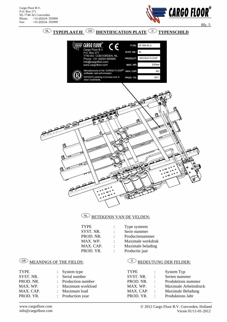
NL TYPEPLAATJE GB IDENTIFICATION PLATE D TYPENSCHILD
NL BETEKENIS VAN DE VELDEN:
TYPE : Type systeem SYST. NR. : Serie nummer PROD. NR. : Productienummer MAX. WP. : Maximale werkdruk MAX. CAP. : Maximale belading PROD. YR. : Productie jaar
GB MEANINGS OF THE FIELDS: D BEDEUTUNG DER FELDER:
TYPE : System type TYPE : System Typ SYST. NR. : Serial number SYST. NR. : Serien nummer PROD. NR. : Production number PROD. NR. : Produktions nummer MAX. WP. : Maximum workload MAX. WP. : Maximale Arbeitsdruck MAX. CAP. : Maximum load MAX. CAP. : Maximale Beladung PROD. YR. : Production year PROD. YR. : Produktions Jahr
2012 Cargo Floor B.V. Coevorden, Holland
Versie 01/11-01-2012 www.cargofloor.com [email protected]
Cargo Floor B.V. P.O. Box 271 NL-7740 AG Coevorden Phone: +31-(0)524- 593900 Fax: +31-(0)524- 593999
Blz. 6
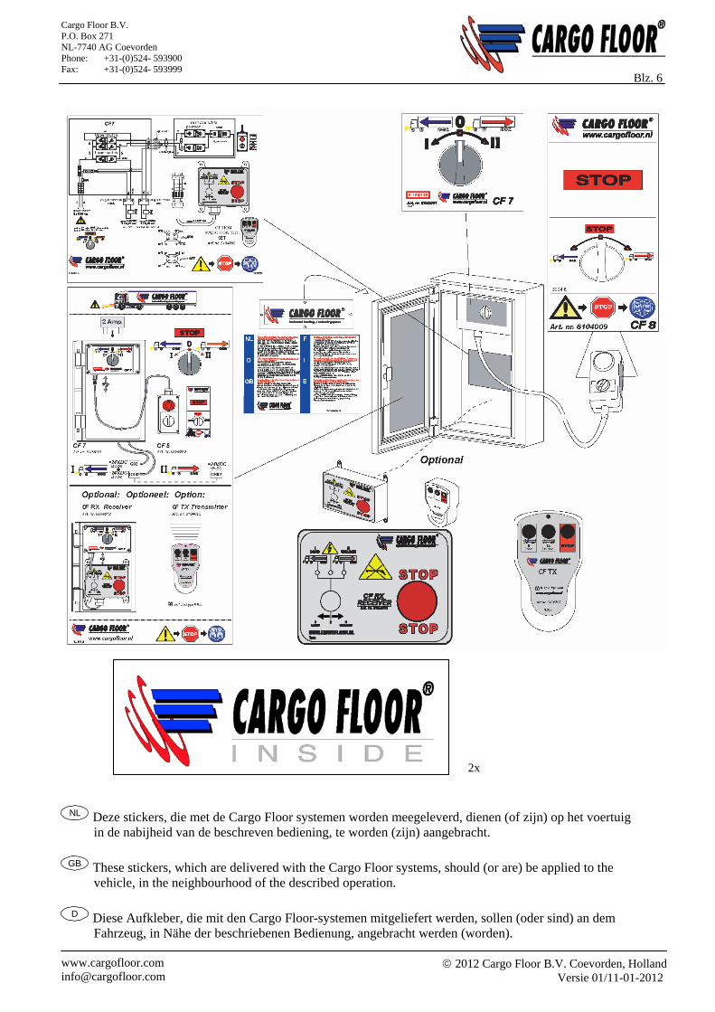
NL Deze stickers, die met de Cargo Floor systemen worden meegeleverd, dienen (of zijn) op het voertuig in de nabijheid van de beschreven bediening, te worden (zijn) aangebracht.
GB These stickers, which are delivered with the Cargo Floor systems, should (or are) be applied to the
vehicle, in the neighbourhood of the described operation.
D Diese Aufkleber, die mit den Cargo Floor-systemen mitgeliefert werden, sollen (oder sind) an dem Fahrzeug, in Nähe der beschriebenen Bedienung, angebracht werden (worden).
2x
2012 Cargo Floor B.V. Coevorden, Holland
Versie 01/11-01-2012 www.cargofloor.com [email protected]
Cargo Floor B.V. P.O. Box 271 NL-7740 AG Coevorden Phone: +31-(0)524- 593900 Fax: +31-(0)524- 593999
Blz. 7
NL BELANGRIJKE ADVIEZEN EN RICHTLIJNEN VOOR DE INGEBRUIKNAME VAN HET CARGO FLOOR LAAD- EN LOSSYSTEEM
Voordat u het Cargo Floor laad- en lossysteem in gebruikt gaat nemen, dient u de volgende adviezen op te volgen en de aangegeven controlepunten te controleren zodat er geen schade aan het Cargo Floor systeem en het voertuig kan ontstaan. Het is noodzakelijk dat u alle aandachtspunten doorneemt voordat u het Cargo Floor systeem in gebruik neemt en er geen lading in het voertuig zit. Ook dient de werking van de verschillende bedien- schakelaars/ventielen vooraf zonder lading te worden uitgevoerd zodat men goed weet hoe het systeem werkt. Ons primaire advies is dit te doen tijdens het ophalen van het voertuig bij uw leverancier zodat een deskundige medewerker eventuele vragen kan beantwoorden en u adequaat kan begeleiden. Belangrijk: Controleer altijd of de door u gewenste en geselecteerde transportrichting (lossen/laden) daadwerkelijk is
geactiveerd en plaatsvindt!! Indien het systeem niet in werking treed zet u het Cargo Floor systeem en de hydraulische pomp uit daarna
dient u altijd onderstaande adviezen en richtlijnen op te volgen. Blijf nooit onnodig lang proberen dit kan tot grote schade aan uw Cargo Floor systeem en/of voertuig leiden.
Na gebruik van het Cargo Floor systeem dient deze en de hydrauliekpomp altijd volledig te worden uitgezet. Schakelaars in de “0” positie, hendel in de neutrale stand.
Bij twijfel of onduidelijkheid rondom deze adviezen en richtlijnen dient u altijd contact op te nemen met uw leverancier of een officiële werkplaats. Ieder Cargo Floor systeem wordt standaard geleverd met een bedieningshandleiding, indien deze niet aanwezig is dient u contact op te nemen met uw leverancier of deze te downloaden via de officiële website van Cargo Floor. WWW.CARGOFLOOR.COM
A) Open altijd eerst de deuren van het voertuig voordat de hydraulische pomp wordt aangezet. Let op! Er kan veel druk staan tegen de deuren waardoor deze met kracht vanzelf kunnen openschieten. Daarnaast bestaat de mogelijkheid dat een deel van de lading bij het openen er vanzelf uitvalt. Gebruik daarom altijd, indien aanwezig, de pneumatische deurvergrendeling
B) 1. Controleer of de (snel) koppelingen van het voertuig correct zijn aangesloten op de P (Pers,min. 20 mm.) en de T (Tank/retour, min 25 mm.). Let er ook op of de koppelingen volledig tot het eind zijn aangedraaid dan wel de volledige weg in elkaar zijn geschoven.
BELANGRIJK: de pers- en retouraansluitingen mogen nooit omgedraaid of verwisseld worden voorkom bij het aansluiten dat er vuil of water in de leidingen komt!
2. Controleer voor het aankoppelen of de aanwezige terugslagkleppen eenvoudig open kunnen (controle; de terugslagkleppen moeten te allen tijde met de vinger kunnen worden opengedrukt, indien dit niet het geval is bestaat de kans dat er opgebouwde druk zit in de hydrauliek leidingen waardoor het systeem niet in werking zal treden).
LET OP: Fout aangesloten of niet geopende hydraulische koppelingen zullen tot ernstige schade aan het Cargo Floor systeem alsmede het voertuig leiden.
C) Het voertuig (pomp) dient te zijn voorzien van haar eigen drukveiligheidsventiel welke dient te zijn afgesteld op maximaal 250 bar. Controleer bij een eventueel aanwezige dubbele functie- hendel (functie; kipper/Cargo Floor) dat deze in de stand Cargo Floor staat. Het is niet toegestaan de maximale ingestelde en toegestane druk van uw Cargo Floor systeem te overschrijden. Een niet juist afgesteld drukveiligheidsventiel kan eventueel tot schade leiden aan het Cargo Floor systeem alsmede het voertuig.
D) Het voertuig dient tijdens de werking altijd op de (hand) rem staan. U dient echter tijdig het voertuig naar voren te bewegen waardoor het voertuig sneller gelost kan worden tevens wordt hierdoor een onnodige overbelasting en slijtage aan de vloer alsmede aan het voertuig voorkomen.
E) Het gebruik van een draadloze afstandsbediening is alleen toegestaan indien de volledige werking is getest voor ieder begin van het laden of lossen. Er dient altijd te worden gecontroleerd of men de functie die men heeft gekozen ook daadwerkelijk in werking is gezet. Als men bijvoorbeeld per abuis de laadfunctie heeft ingedrukt terwijl men wil lossen dan zal er onherroepelijk schade kunnen ontstaan aan het Cargo Floor systeem alsmede het voertuig.
2012 Cargo Floor B.V. Coevorden, Holland
Versie 01/11-01-2012 www.cargofloor.com [email protected]
Cargo Floor B.V. P.O. Box 271 NL-7740 AG Coevorden Phone: +31-(0)524- 593900 Fax: +31-(0)524- 593999
Blz. 8 F) Tijdens de werking van het Cargo Floor systeem dienen alle aanwezige
STOP- en bedienknoppen/hendels vrij toegankelijk te zijn. G) Het persfilterelement dient tenminste 1 keer per jaar te worden vervangen. Indien de koppelingen tussen
het voertuig en het Cargo Floor systeem regelmatig worden losgemaakt is het raadzaam regelmatig het persfilter te controleren op aanwezige vervuiling en het persfilterelement vaker te vervangen. Controleer ook het eventueel aanwezige retourfilter (geen levering Cargo Floor) Bij het niet tijdig vervangen van een filterelement bestaat de mogelijkheid dat er schade dan wel storingen ontstaan aan het Cargo Floor systeem alsmede aan het voertuig.
H) Alle bewegende delen van het Cargo Floor systeem dienen te zijn afgeschermd. Daarnaast mag men zich nooit bevinden binnen 10 meter van een in werking zijnd Cargo Floor systeem.
I) Bij storingen/werkzaamheden mag het Cargo Floor systeem alleen benaderd worden nadat alle apparatuur, waaronder de hydraulische pomp, is uitgeschakeld. En het Cargo Floor systeem elektrisch en hydraulisch is losgekoppeld van voeding en pomp.
J) De boutbevestigingen van de aluminium vloerprofielen aan het Cargo Floor systeem dienen regelmatig te worden gecontroleerd op het eventueel loszitten. Controle kan eenvoudig geschieden in het voertuig op de vloer door vakbekwaampersoneel. Hierbij dient het Cargo Floor systeem in onbeladen toestand ingeschakeld te worden en dient de persoon zijn vinger half op de vloerplank en de aanwezige schroef te leggen. Er mag hierbij geen onderlinge beweging/speling tussen vloerprofiel en schroef merkbaar zijn. Het niet controleren van deze bevestigingen kan eventueel tot schade leiden aan het Cargo Floor systeem. Tijdens deze controle dient er een tweede persoon aanwezig te zijn om het Cargo Floor systeem uit te kunnen schakelen.
K) Controleer of de minimaal voorgeschreven oliehoeveelheid aanwezig is (150 ltr.). Te weinig olie in de hydrauliektank zal tot schade leiden aan zowel de pomp alsmede het Cargo Floor systeem.
L) Let erop dat het systeem nooit meer slagen maakt dan de maximaal toegestane 16 arbeidsslagen per minuut. Alleen een Cargo Floor systeem van het type Powerspeed, mag tot max. 23 arbeidslagen per minuut maken. Een hoger aantal arbeidsslagen kan tot schade leiden aan het Cargo Floor systeem alsmede aan het voertuig.
M) Het gebruik van te kleine diameters van de hydrauliekleidingen, koppelingen en slangen zal tot schade leiden.
N) Bij het niet in werking komen of bij de constatering van een onjuiste werking van het Cargo Floor systeem dient het Cargo Floor systeem en de hydrauliekpomp direct te worden uitgezet. Hierna zal men eerst alle controlepunten moeten doorlopen voordat men de pomp en het Cargo Floor systeem weer mag inschakelen. Om oververhitting van de olie te voorkomen dient u regelmatig de olietemperatuur te controleren door VOORZICHTIG en BEHOEDZAAM met uw hand aan de leiding en of olietank te voelen. Indien u uw hand hier niet op kan houden dient u direct te stoppen WAARSCHUWING: AANRAKING VAN OVERVERHITTE OLIE EN ONDERDELEN KAN TOT BRANDWONDEN LEIDEN!
O) De oorzaak van het niet werken of in werking komen van het Cargo Floor systeem kan ook liggen aan eventueel andere aanwezige hydraulische componenten die al dan niet op hetzelfde hydraulische circuit van het Cargo Floor systeem zijn aangesloten.
P) Het eventueel vastklemmen van de vloerprofielen door het vervoer van verkeerde niet toegestane lading alsmede het eventueel vastvriezen van de vloer of het product aan de vloer kan eventueel tot schade leiden aan het Cargo Floor systeem alsmede aan het voertuig. Advies: bij bevriezing stop het systeem en probeer een hal (verwarmde ruimte) te vinden om het product te laten ontdooien.
Q) Omdat de elektrische stroom voorziening van het Cargo Floor systeem vaak wordt aangesloten op het licht circuit van het voertuig is het raadzaam de verlichting tijdens de werking van het systeem in te schakelen en ingeschakeld te houden.
R) Onderhoud van en reparatie aan het Cargo Floor systeem mag alleen door bekwaam personeel worden uitgevoerd. Er dienen te allen tijde originele Cargo Floor onderdelen te worden ingezet om een toekomstige goede en lange levensduur van het Cargo Floor systeem te kunnen garanderen.
S) Met betrekking tot het maximaal gewicht dat u mag laden op uw voertuig dienen te allen tijde de richtlijnen van de wet gevolgd te worden. Ook als het systeem meer kan transporteren bepaalt de wet de maximale limiet. Veel te zware belading kan eventueel ook tot schade leiden aan het Cargo Floor systeem alsmede aan het voertuig.
T) Controleer of de juiste type en kwaliteit hydrauliek olie is toegepast Het gebruik van verkeerde olie kan eventueel tot schade leiden aan het Cargo Floor systeem alsmede aan de pomp.
2012 Cargo Floor B.V. Coevorden, Holland
Versie 01/11-01-2012 www.cargofloor.com [email protected]
Cargo Floor B.V. P.O. Box 271 NL-7740 AG Coevorden Phone: +31-(0)524- 593900 Fax: +31-(0)524- 593999
Blz. 9 U) Controleer het voertuig op de juiste spanning / voltage. Alsmede of er geen open elektrische verbindingen
zijn. Een ondeugdelijke elektrische installatie kan eventueel tot schade leiden aan het Cargo Floor systeem alsmede aan het voertuig.
V) Controleer of het eventueel aanwezige kopschot soepel en goed functioneert. Een goed functionerend kopschot zorgt voor een schone en snelle lossing van het product. Een niet goed functionerend kopschot kan tot verlenging van de lostijd en schade aan het voertuig leiden.
W) Gebruik van het Cargo Floor systeem door een onbekwaam persoon kan eventueel tot schade leiden aan het Cargo Floor systeem alsmede aan het voertuig.
X) Een te hoge olietemperatuur zal absoluut leiden tot schade aan het Cargo Floor systeem alsmede aan de overige hydraulische componenten waaronder de pomp.
Y) Het is te allen tijde raadzaam om ervoor te zorgen dat het Cargo Floor systeem wordt gestopt op het moment dat alle zuigerstangen ingetrokken staan. (Dit is normaliter het geval als alle vloerprofielen in z’n geheel richting de loskant (deuren van het voertuig) staat). Indien de zuigerstangen niet zijn ingetrokken kan dit tot schade leiden aan het Cargo Floor systeem.
Z) Om schade aan de vloerprofielen te voorkomen dient men voorzichtig te zijn en de storthoogte zoveel mogelijk te beperken. Daarnaast bestaat de mogelijkheid dat door het toch transporteren van niet toegestane agressieve, corrosieve, hete, harde, scherpe en kleverige materialen schade kan ontstaan aan het Cargo Floor systeem alsmede aan het voertuig. Vermijd altijd het laden en lossen van scherpe producten U bent hierbij altijd zeker indien de lading zachter is dan de hardheid van de vloerprofielen, gebruik bij twijfel een beschermkleed of raadpleeg uw leverancier.
AA) Heftruckoverrijdbaarheid. In principe zijn alle vloeren overrijdbaar met een heftruck maar raadpleeg altijd vooraf uw leverancier welke belastingen op uw voertuig zijn toegestaan.
Overbelasting kan absoluut leiden tot schade aan het Cargo Floor systeem alsmede aan het voertuig. BB) Indien men de noodbediening(en) heeft gebruikt dienen deze altijd weer in de oorspronkelijke niet
geactiveerde stand terug te worden gezet. CC) Controleer tijdens het werken van het systeem of de olie niet te heet wordt. Dit kunt u eenvoudig doen
door tijdens de werking met uw hand aan de zijkant van de olietank te voelen. Indien de olie zo heet is dat u uw hand niet op de tank kunt houden dient u de pomp direct uit te zetten om de olie te laten afkoelen. Daarnaast dient u te controleren waar de oorzaak van het te heet worden van de olie zou kunnen liggen. Blijf nooit doorgaan met laden of lossen als de olie te heet is dat zal onherroepelijk tot schade aan het Cargo Floor systeem alsmede aan de overige hydraulische componenten leiden.
WAARSCHUWING: AANRAKING VAN OVERVERHITTE OLIE EN ONDERDELEN KAN TOT BRANDWONDEN/LETSEL LEIDEN!
DD) Bij het laden en lossen van stukgoed is het van belang dat men een gelijkmatige gewichtsverdeling op de vloer realiseert. Zonder gelijkmatige gewichtsverdeling op de vloer bestaat de kans dat de lading blijft staan. Tip: plaats bij transport van pallets zonodig zacht houten planken van ca. 300 x 18 x 2350 mm. om de druk beter te verdelen.
GARANTIE: Eventuele garantie wordt alleen toegekend mits vooraf toestemming door Cargo Floor B.V. is verleend! Bij garantie aanvragen dient u altijd vooraf een garantieaanvraagformulier in te vullen en Cargo Floor B.V. toe te sturen. Het garantieaanvraagformulier kunt u eenvoudig via het internet vinden op www.cargofloor.com. Het is hierbij altijd belangrijk het Cargo Floor systeemnummer op te geven.
2012 Cargo Floor B.V. Coevorden, Holland
Versie 01/11-01-2012 www.cargofloor.com [email protected]
Cargo Floor B.V. P.O. Box 271 NL-7740 AG Coevorden Phone: +31-(0)524- 593900 Fax: +31-(0)524- 593999
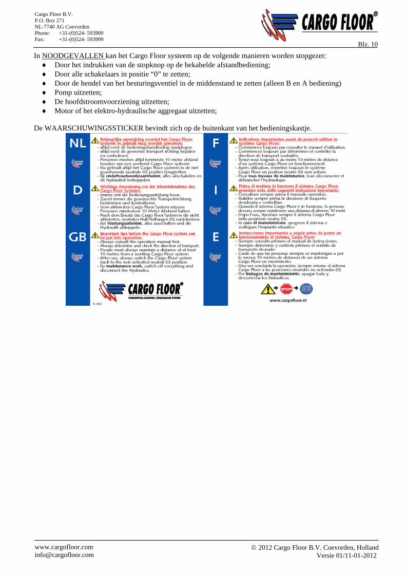
Blz. 10 In NOODGEVALLEN kan het Cargo Floor systeem op de volgende manieren worden stopgezet:
Door het indrukken van de stopknop op de bekabelde afstandbediening; Door alle schakelaars in positie “0” te zetten; Door de hendel van het besturingsventiel in de middenstand te zetten (alleen B en A bediening) Pomp uitzetten; De hoofdstroomvoorziening uitzetten; Motor of het elektro-hydraulische aggregaat uitzetten;
De WAARSCHUWINGSSTICKER bevindt zich op de buitenkant van het bedieningskastje.
2012 Cargo Floor B.V. Coevorden, Holland
Versie 01/11-01-2012 www.cargofloor.com [email protected]
Cargo Floor B.V. P.O. Box 271 NL-7740 AG Coevorden Phone: +31-(0)524- 593900 Fax: +31-(0)524- 593999
Blz. 11
GB IMPORTANT RECOMMENDATIONS AND GUIDELINES FOR THE COMMISSIONING
Before putting the Cargo Floor loading and unloading system into operation, follow the recommendations provided below and check the specified checkpoints to avoid damage to the Cargo Floor system and the vehicle. Please review the important instructions before operating the Cargo Floor system and loading cargo into the vehicle. Likewise, before loading cargo, check the operation of the various control switches/valves to familiarise yourself with how the system works. We strongly recommend that you perform these checks when picking up the vehicle from the dealer so that a resident expert can answer your questions and provide you with any necessary advice or guidance you may require. Important:
Always check that the selected loading or unloading direction is actually activated and occurring!! If the system fails to start, turn off the Cargo Floor system and the hydraulic pump and follow the
recommendations and guidelines provided below. Do not repeatedly try to start the system as this may result in damage to your Cargo Floor system and/or vehicle.
After use, turn off the Cargo Floor system and hydraulic pump. Set switches to the "0" position and the lever in neutral.
In case of doubt or uncertainty about these recommendations and guidelines, always contact your dealer or an official workshop. The Cargo Floor system comes standard with an operating manual, but is this has not been supplied, please contact your dealer or download it from the official Cargo Floor website: WWW.CARGOFLOOR.COM A) Always open the vehicle's doors before turning on the hydraulic pump. Note! Build-up of pressure against
the doors can force them open, which may cause some of the cargo to fall out of the vehicle. That is why it is always advisable to use the pneumatic lock, if provided.
B) 1. Check that the vehicle's (quick-detachable) couplings are properly connected to the P (Pressure line, min. 20mm) and the T (tank/return line, min. 25mm). Also check that the couplings are fully tightened or slid completely into each other.
IMPORTANT: the pressure and return line connectors may not be reversed or exchanged to prevent dirt or water from entering the lines when connecting them!
2. Before connecting, check that the non-return valves can open easily (check: the non-return valves should open easily when pressed with the finger, if not, potential pressure build-up in the hydraulic lines may be preventing the system from starting).
NOTE: Incorrectly connected or unopened hydraulic couplings will cause serious damage to the Cargo Floor system and the vehicle.
C) The vehicle (pump) must be fitted with a pressure relief valve that is set to 250 bar. If fitted, check that the dual-function lever (function: tipper/Cargo Floor) is in the Cargo Floor position. Pressure may not exceed the maximum adjusted and allowable operating pressure of the Cargo Floor system. An incorrectly adjusted pressure relief valve can cause damage to the Cargo Floor system and the vehicle.
D) During operation, the (hand)brake of the vehicle must always be applied. You must, however, move the vehicle forward on time to unload it quickly in order to prevent unnecessary strain and wear to the floor and the vehicle.
E) Use of a wireless remote control is permitted only if it is fully tested before the start of each loading or unloading operation. Always check if the function you have selected is actually activated and taking place. If, for example, you have accidentally pressed the load function when you actually meant to press the unload function, irreversible damage may occur to the Cargo Floor system and the vehicle.
F) During operation of the Cargo Floor system, all existing STOP and control knobs/levers must be freely accessible. G) The pressure filter element needs to be replaced at least once a year. If the couplings between the vehicle and
the Cargo Floor system are regularly removed, it is advisable to check the pressure filter for dirt build-up and replace the pressure filter element more often, if necessary. If provided, also check the return filter (not supplied with the Cargo Floor). Failure to replace a filter element on time may cause damage to or malfunctions in the Cargo Floor system and the vehicle.
2012 Cargo Floor B.V. Coevorden, Holland
Versie 01/11-01-2012 www.cargofloor.com [email protected]
Cargo Floor B.V. P.O. Box 271 NL-7740 AG Coevorden Phone: +31-(0)524- 593900 Fax: +31-(0)524- 593999
Blz. 12 H) Moving parts must be shielded. Always maintain at least 10m distance from the Cargo Floor system when it
is in operation. I) In the event of malfunctions/maintenance work, you may approach the Cargo Floor system only if all
equipment, including the hydraulic pump, have been shut off, and the Cargo Floor system and the electro-hydraulic aggregate have been disconnected from the power supply and pump.
J) Regularly check and, if necessary, tighten any loose bolts that secure the aluminium floor profiles to the Cargo Floor system. All such checks can simply be performed inside the vehicle itself by qualified personnel. The Cargo Floor system must, however, be turned on in unloaded condition and the person performing the check must place his finger half on the floor profile and half on the bolt. There should be no appreciable movement/space between the floor profile and bolt. Failure to check these bolts may lead to damage to the Cargo Floor system. During this check, a second person must also be present to switch off the Cargo Floor system.
K) Check that the minimum required amount of oil is present (150L). Too little oil in the hydraulic tank will cause damage to both the pump and the Cargo Floor system.
L) Do not allow the number of strokes to exceed the maximum allowable 16 power strokes per minute. Only a Powerspeed Cargo Floor system may deliver up to 23 beats per minute. A higher number of power strokes can cause damage to the Cargo Floor system and the vehicle.
M) Hydraulic lines, couplings and hoses with very small diameters will cause damage. N) If the Cargo Floor system fails to start or operates incorrectly, the Cargo Floor system and the hydraulic
pump must be shut down immediately. Subsequently, check all the checkpoints before switching the pump and the Cargo Floor system back on. To prevent the oil from overheating, regularly check the oil temperature by CAREFULLY and CAUTIOUSLY touching the line and or oil tank. If either is too hot to the touch, stop touching them right away. WARNING: TOUCHING OVERHEATED OIL AND COMPONENTS CAN CAUSE BURNS!
O) The cause of failure or malfunctioning of the Cargo Floor system may also be due to other hydraulic components that may or may not be connected to the same hydraulic circuit of the Cargo Floor system.
P) Jamming of the floor profiles caused by the transport of abnormal loads and or the freezing of the floor or of the product to the floor may result in damage to the Cargo Floor system and the vehicle. Recommendation: in the event of freezing, stop the system and try to find a hall (heated area) to allow the product to thaw.
Q) Because the electrical power supply of the Cargo Floor system is often connected to the lighting circuit of the vehicle, it is advisable to turn on the lighting throughout the operation of the system.
R) Maintenance and repairs to the Cargo Floor system may be only performed by qualified personnel. Use only original Cargo Floor components to ensure maximum reliability and long service life.
S) Maximum cargo weight is subject to the limits set by law and applicable regulations. Even if the system can transport heavier loads, the law determines the maximum limit. Excessively heavy cargo can cause damage to the Cargo Floor system and the vehicle.
T) Check that the correct type and quality of hydraulic oil is used. The use of incorrect oil type may cause damage to the Cargo Floor system and the pump.
U) Check the vehicle for correct voltage. Make sure there are no open electrical connections. A faulty electrical system can cause damage to the Cargo Floor system and the vehicle.
V) Check that the bulkhead, if present, is functioning smoothly and properly. A properly functioning bulkhead ensures that the product is unloaded in a clean and quick fashion. A malfunctioning bulkhead may extend the unloading time and cause damage to the vehicle.
W) Use of the Cargo Floor system by unqualified personnel can cause damage to the Cargo Floor system and the vehicle.
X) Excessively high oil temperatures will cause damage to the Cargo Floor system and other hydraulic components, such as the pump.
Y) It is at all times advisable to stop the Cargo Floor system when all the piston rods are retracted. This is usually the case when the floor profiles are positioned towards the unloading end (vehicle doors). Unretracted piston rods may cause damage to the Cargo Floor system.
Z) To prevent damage to the floor profiles, exercise caution and limit the dump height as much as possible. The transport of unauthorised goods, such as aggressive, corrosive, hot, hard, sharp and viscous materials may cause damage to the Cargo Floor system and the vehicle. Avoid loading and unloading sharp objects. Loads that are softer than the hardness of the floor profiles will extend the service life of your system; if in doubt, use a protective cloth or consult your dealer.
2012 Cargo Floor B.V. Coevorden, Holland
Versie 01/11-01-2012 www.cargofloor.com [email protected]
Cargo Floor B.V. P.O. Box 271 NL-7740 AG Coevorden Phone: +31-(0)524- 593900 Fax: +31-(0)524- 593999
Blz. 13 AA) Forklift trafficable. In principle, the floors are completely trafficable and can be driven over by forklifts, but
always consult your dealer for advice on the maximum loads allowed on your vehicle. Overloading will cause damage to the Cargo Floor system and the vehicle. BB) Always return emergency control(s) to their original non-activated position after use. CC) During the operation of the system, test the temperature of the oil by touching the side of the tank. If the oil
is so hot that you cannot continue to touch the tank, switch off the pump to allow the oil to cool off and determine what is causing the overheating. Stop loading or unloading if the oil is too hot, as this will irreversibly cause damage to the Cargo Floor system and the other hydraulic components.
WARNING: TOUCHING OVERHEATED OIL AND COMPONENTS CAN CAUSE BURNS AND INJURIES!
DD) During loading and unloading operations, the load should be spread to give an even weight distribution over the floor area, otherwise the load may stall. Tip: when transporting pallets, place softwood boards of 300 x 18 x 2350 mm to distribute the pressure more evenly.
WARRANTY: Warranty is subject to prior approval by Cargo Floor B.V.! To request warranty coverage, visit www.cargofloor.com to fill out and submit the warranty application form provided there; do not forget to include your Cargo Floor system number on the form.
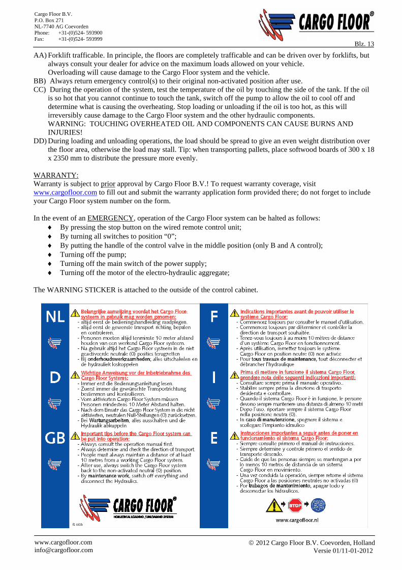
In the event of an EMERGENCY, operation of the Cargo Floor system can be halted as follows:
By pressing the stop button on the wired remote control unit; By turning all switches to position “0”; By putting the handle of the control valve in the middle position (only B and A control); Turning off the pump; Turning off the main switch of the power supply; Turning off the motor of the electro-hydraulic aggregate;
The WARNING STICKER is attached to the outside of the control cabinet.
2012 Cargo Floor B.V. Coevorden, Holland
Versie 01/11-01-2012 www.cargofloor.com [email protected]
Cargo Floor B.V. P.O. Box 271 NL-7740 AG Coevorden Phone: +31-(0)524- 593900 Fax: +31-(0)524- 593999
Blz. 14
D WICHTIGE EMPFEHLUNGEN UND RICHTLINIEN FÜR DIE INBETRIEBNAHME
Bevor Sie das Cargo Floor Lade- und Entladesystem einsetzen, müssen Sie folgende Empfehlungen befolgen und die angegebenen Kontrollpunkte prüfen, sodass das Cargo Floor System und das Fahrzeug nicht beschädigt wird. Es ist notwendig, dass Sie alle Punkte beachten, bevor Sie das Cargo Floor System in Gebrauch nehmen und dass sich im Fahrzeug keine Ladung befindet. Außerdem muss die Funktion der verschiedenen Bedienungsschalter/-ventile im Vorfeld ohne Ladung ausgeführt werden, sodass man gut darüber informiert ist, wie das System funktioniert. Unsere erste Empfehlung ist, dies während des Abholens des Fahrzeugs bei Ihrem Lieferanten zu tun, sodass ein fachkundiger Mitarbeiter eventuelle Fragen beantworten und Sie adäquat begleiten kann. Wichtig: Kontrollieren Sie immer, ob die von Ihnen gewünschte und gewählte Transportrichtung (Entladen/Laden)
tatsächlich aktiviert ist und stattfindet!! Falls das System nicht startet, stellen Sie das Cargo Floor System und die hydraulische Pumpe aus.
Anschließend befolgen Sie die folgenden Empfehlungen und Richtlinien. Versuchen Sie niemals unnötig lange etwas Bestimmtes zu erreichen, das kann zu großem Schaden an Ihrem Cargo Floor System oder am Fahrzeug führen.
Nach Gebrauch des Cargo Floor Systems müssen dieses und die Hydraulikpumpe immer vollständig ausgeschaltet werden. Schalter auf „0“, Hebel auf neutraler Position.
Bei Zweifeln oder Unklarheiten zu diesen Empfehlungen und Richtlinien müssen Sie immer Kontakt mit Ihrem Lieferanten oder einer offiziellen Werkstatt aufnehmen. Jedes Cargo Floor System wird standardmäßig mit Bedienungsanleitung geliefert. Falls diese nicht vorhanden ist, nehmen Sie bitte Kontakt zu Ihrem Lieferanten auf oder laden Sie sich die Anleitung von der offiziellen Cargo Floor Webseite herunter. WWW.CARGOFLOOR.COM
A) Öffnen Sie die Türen des Fahrzeugs immer, bevor die Hydraulikpumpe angestellt wird. HINWEIS: Die Türen
können unter hohem Druck stehen, sodass sie mit Kraft von selbst aufspringen. Außerdem kann es passieren, dass ein Teil der Ladung beim Öffnen herausfällt. Verwenden Sie darum immer, falls vorhanden, die pneumatische Türverriegelung.
B) 1. Kontrollieren Sie, ob die (Schnell-) Kupplungen des Fahrzeugs korrekt an P (Presse, min. 20 mm) und T (Tank/Retour, min 25 mm) angeschlossen sind. Achten Sie auch darauf, dass die Verbindungen vollständig bis zum Ende festgedreht bzw. über die ganze Länge hineingeschoben sind.
WICHTIG: die Press- und Rückanschlüsse dürfen niemals umgedreht oder verwechselt werden. Vermeiden Sie beim Anschließen, dass Schmutz oder Wasser in die Leitungen gelangt!
2. Kontrollieren Sie vor dem Ankuppeln, ob sich die Rückschlagventile leicht öffnen (Kontrolle; die Rückschlagventile müssen jederzeit mit dem Finger aufgedrückt werden können, ist das nicht der Fall, besteht das Risiko, dass in den hydraulischen Leitungen aufgebauter Druck herrscht, sodass das System nicht funktioniert).
HINWEIS: Falsch angeschlossene oder nicht geöffnete hydraulische Verbindungen führen zu schwerem Schaden am Cargo Floor System sowie am Fahrzeug.
C) Das Fahrzeug (Pumpe) muss mit eigenem Drucksicherheitsventil ausgestattet sein, welches auf maximal 250 bar eingestellt sein muss. Kontrollieren Sie bei eventuell vorhandenem doppeltem Funktionshebel (Funktion; Kipper/Cargo Floor), dass dieser auf Cargo Floor steht. Es ist nicht gestattet den maximal eingestellten und erlaubten Druck Ihres Cargo Floor Systems zu überschreiten. Ein nicht korrekt eingestelltes Drucksicherheitsventil kann eventuell zu Schaden am Cargo Floor System und am Fahrzeug führen.
D) Das Fahrzeug muss während des Systembetriebs immer auf (Hand-) Bremse stehen. Sie müssen das Fahrzeug jedoch rechtzeitig nach vorne bewegen, sodass es schneller entladen werden kann. Außerdem wird dadurch unnötige Überlastung und unnötiger Verschleiß am Boden und am Fahrzeug vermieden.
E) Die Verwendung einer kabellosen Fernbedienung ist nur gestattet, wenn die vollständige Funktion vor jedem Lade- oder Entladebeginn getestet wurde. Es muss immer kontrolliert werden, ob die gewählte Funktion auch tatsächlich in Betrieb ist. Wenn man beispielsweise irrtümlich die Ladefunktion gedrückt hat, während man entladen möchte, kann irreparabler Schaden am Cargo Floor System sowie am Fahrzeug entstehen.
2012 Cargo Floor B.V. Coevorden, Holland
Versie 01/11-01-2012 www.cargofloor.com [email protected]
Cargo Floor B.V. P.O. Box 271 NL-7740 AG Coevorden Phone: +31-(0)524- 593900 Fax: +31-(0)524- 593999
Blz. 15 F) Während des Betriebs des Cargo Floor Systems müssen alle vorhandenen STOP- und Bedienungsschalter/-hebel frei zugänglich sein. G) Das Pressfilterelement muss mindestens ein Mal jährlich ausgetauscht werden. Falls die Kupplungen
zwischen Fahrzeug und Cargo Floor System regelmäßig gelöst werden, ist es ratsam den Pressfilter regelmäßig auf Schmutz zu kontrollieren und häufiger auszutauschen. Kontrollieren Sie auch eventuelle Rückfilter (keine Lieferung von Cargo Floor). Bei verspätetem Austausch eines Filterelements besteht das Risiko, dass Schaden oder Störungen am Cargo Floor System oder am Fahrzeug entstehen.
H) Alle beweglichen Teile des Cargo Floor Systems müssen abgeschirmt sein. Zudem darf man sich niemals innerhalb von 10 Metern eines laufenden Cargo Floor Systems aufhalten.
I) Bei Störungen/in Betrieb darf sich dem Cargo Floor System nur genähert werden, nachdem alle Geräte einschließlich der Hydraulikpumpe ausgeschaltet wurden. Zudem muss das Cargo Floor System elektrisch und hydraulisch von Strom und Pumpe getrennt sein.
J) Die Bolzenbefestigungen der Aluminium-Bodenprofile am Cargo Floor System müssen regelmäßig kontrolliert werden, ob sie sich eventuell gelöst haben. Die Kontrolle kann leicht im Fahrzeug auf dem Boden durch fachkundiges Personal durchgeführt werden. Dazu muss das Cargo Floor System in unbeladenem Zustand eingeschaltet werden und die Person muss ihren Finger halb auf das Bodenbrett und die Schraube legen. Dabei darf zwischen Bodenprofil und Schraube keine merkliche Bewegung/kein Spiel entstehen. Werden diese Befestigungen nicht kontrolliert, kann dies eventuell zu Schaden am Cargo Floor System oder am Fahrzeug führen. Während dieser Kontrolle muss eine zweite Person anwesend sein, um das Cargo Floor System ausschalten zu können.
K) Kontrollieren Sie, ob die vorgeschriebene Mindestmenge an Öl vorhanden ist (150 ltr). Zu wenig Öl im Hydrauliktank führt zu Schäden an der Pumpe und am Cargo Floor System.
L) Achten Sie darauf, dass das System nicht mehr Arbeitstakte macht als die maximal erlaubten 16 Takte pro Minute. Nur ein Cargo Floor System vom Typ Powerspeed darf bis zu 23 Takte pro Minute machen. Eine höherer Takt kann zu Schäden am Cargo Floor System und am Fahrzeug führen.
M) Die Verwendung von Hydraulikleitungen, Verbindungen und Schläuchen mit zu kleinem Durchmesser führt zu Schäden.
N) Bei ausbleibendem Betrieb oder der Feststellung fehlerhaften Betriebs des Cargo Floor Systems müssen das Cargo Floor System und die Hydraulikpumpe sofort ausgeschaltet werden. Erst danach werden alle Kontrollpunkte durchlaufen, bevor die Pumpe und das Cargo Floor System wieder eingeschaltet werden dürfen. Um Überhitzung des Öls zu vermeiden, müssen Sie regelmäßig die Öltemperatur kontrollieren, indem Sie VORSICHTIG und BEHUTSAM mit der Hand an der Leitung oder am Öltank fühlen. Wenn es dort für die Hand zu heiß ist, müssen Sie sofort das System stoppen. WARNUNG: DIE BERÜHRUNG ÜBERHITZTEN ÖLS UND ÜBERHITZTER TEILE KANN ZU BRANDVERLETZUNGEN FÜHREN!
O) Funktioniert das Cargo Floor System nicht oder es startet nicht richtig, kann das eventuell auch an anderen hydraulischen Komponenten liegen, die an den Hydraulikkreislauf des Cargo Floor Systems angeschlossen sind.
P) Festklemmen der Bodenprofile durch den Transport falscher, nicht gestatteter Ladung sowie eventuelles Festfrieren des Bodens oder des Produkts am Boden kann eventuell zu Schaden am Cargo Floor System sowie am Fahrzeug führen. EMPFEHLUNG: bei Frost das System anhalten und eine Halle (beheizten Raum) aufsuchen, um das Produkt aufzutauen.
Q) Da die Stromzufuhr des Cargo Floor Systems häufig an die Lichtschaltung des Fahrzeugs angeschlossen wird, ist es ratsam die Beleuchtung während des laufenden Systembetriebs einzuschalten und eingeschaltet zu lassen.
R) Wartungen und Reparaturen am Cargo Floor System dürfen nur von fachkundigem Personal durchgeführt werden. Es müssen immer Original-Ersatzteile von Cargo Floor System eingesetzt werden um eine gute und lange Lebensdauer des Cargo Floor Systems garantieren zu können.
S) Für das maximal erlaubte Ladegewicht müssen Sie immer die gesetzlichen Richtlinien befolgen. Auch, wenn das System mehr transportieren kann, wird die Höchstgrenze durch das Gesetz bestimmt. Viel zu schwere Ladung kann zu Schäden am Cargo Floor System und am Fahrzeug führen.
T) Kontrollieren Sie, ob beim Hydrauliköl der richtige Typ und die richtige Qualität verwendet wird. Die Verwendung des falschen Öls kann zu Schaden am Cargo Floor System sowie an der Pumpe führen.
U) Prüfen Sie am Fahrzeug die richtige Spannung. Prüfen Sie auch, ob es offene elektrische Verbindungen gibt. Eine ungeeignete elektrische Installation kann zu Schäden am Cargo Floor System und am Fahrzeug führen.
2012 Cargo Floor B.V. Coevorden, Holland
Versie 01/11-01-2012 www.cargofloor.com [email protected]
Cargo Floor B.V. P.O. Box 271 NL-7740 AG Coevorden Phone: +31-(0)524- 593900 Fax: +31-(0)524- 593999
Blz. 16 V) Kontrollieren Sie, ob die eventuell vorhandene Stirnwand leicht und gut funktioniert. Eine gut
funktionierende Stirnwand sorgt für eine saubere und schnelle Entladung des Produkts. Eine schlecht funktionierende Stirnwand kann zur Verlängerung der Entladezeit und zu Schaden am Fahrzeug führen.
W) Bedienung des Cargo Floor Systems durch eine fachlich ungeeignete Person kann zu Schaden am Cargo Floor System sowie am Fahrzeug führen.
X) Zu hohe Öltemperatur führt in jedem Fall zu Schaden am Cargo Floor System sowie an den anderen hydraulischen Komponenten, unter anderem an der Pumpe.
Y) Es ist immer ratsam das Cargo Floor System anzuhalten, sobald alle Kolbenstangen eingezogen sind. (Das ist normalerweise der Fall, wenn alle Bodenprofile vollständig zur Entladeseite hin (Fahrzeugtüren) ausgerichtet sind.) Falls die Kolbenstangen nicht eingezogen sind, kann das zu Schaden am Cargo Floor System führen.
Z) Um Schaden an den Bodenprofilen zu vermeiden, muss man vorsichtig sein und die Ladehöhe soweit wie möglich begrenzen. Zudem kann durch den Transport nicht gestatteter aggressiver, korrosiver, heißer, harter, scharfkantiger und klebriger Materialien Schaden am Cargo Floor System sowie am Fahrzeug entstehen. Vermeiden Sie immer das Laden und Entladen scharfkantiger Produkte. Sie sind immer sicher, wenn die Ladung weicher ist als das Material der Bodenprofile. Benutzen Sie im Zweifel eine Schutzdecke oder fragen Sie Ihren Lieferanten.
AA) Gabelstaplerbefahrbahrkeit Im Prinzip können alle Böden mit einem Gabelstapler befahren werden, erkundigen Sie sich aber immer zuvor bei Ihrem Lieferanten, welche Belastungen für Ihr Fahrzeug erlaubt sind.
Überlastung kann zu Schäden am Cargo Floor System und am Fahrzeug führen. BB) Falls man die Notbedienung(en) gebraucht hat, müssen sie immer wieder in den nicht aktivierten
Ursprungsstand zurückgesetzt werden. CC) Kontrollieren Sie bei Betrieb des Systems, dass das Öl nicht zu heiß wird. Dies können Sie einfach tun,
indem Sie bei Betrieb mit der Hand an der Seite des Öltanks fühlen. Falls das Öl so heiß ist, dass Sie die Hand nicht auf dem Tank belassen können, müssen Sie die Pumpe direkt ausstellen um das Öl abkühlen zu lassen. Außerdem können Sie kontrollieren, was die Ursache des zu heißen Öls sein könnte. Beenden Sie das Laden und Entladen sofort, sobald das Öl zu heiß ist, sonst kann irreparabler Schaden am Cargo Floor System sowie an den restlichen hydraulischen Komponenten entstehen.
ACHTUNG: DIE BERÜHRUNG ÜBERHITZTEN ÖLS UND ÜBERHITZTER TEILE KANN ZU BRANDVERLETZUNGEN FÜHREN!
DD) Beim Laden und Entladen von Stückgut ist es wichtig, dass man eine gleichmäßige Gewichtsverteilung auf dem Fußboden schafft. Ohne gleichmäßige Gewichtsverteilung auf dem Fußboden besteht die Gefahr, dass die Ladung stehen bleibt. Tipp: Legen Sie beim Transport von Paletten gegebenenfalls weiche Holzplanken von ca. 300 x 18 x 2350 mm aus um den Druck besser zu verteilen.
GARANTIE: Eine Garantie wird nur gewährt, wenn zuvor die Zustimmung von Cargo Floor B.V. erteilt wurde! Bei Garantieanfragen müssen Sie immer zuvor ein Anforderungsformular ausgefüllt an Cargo Floor B.V. schicken. Das Formular finden Sie im Internet unter www.cargofloor.com. Dabei ist es wichtig die Cargo Floor Systemnummer anzugeben.
2012 Cargo Floor B.V. Coevorden, Holland
Versie 01/11-01-2012 www.cargofloor.com [email protected]
Cargo Floor B.V. P.O. Box 271 NL-7740 AG Coevorden Phone: +31-(0)524- 593900 Fax: +31-(0)524- 593999
Blz. 17 Bei einem NOTFALL kann das Cargo Floor System durch eine der nachstehenden Maßnahmen sofort abgeschaltet werden:
Betätigen der Stopptaste an der Kabel gesteuerten Fernbedienung; Alle Schalter auf "0" stellen; Durch die Hebel in die mittlere Position zu stellen (nur B und A Bedienung); Pumpe ausschalten; Hauptstromversorgung ausschalten; Motor oder elektro-hydraulisches Aggregat ausschalten.
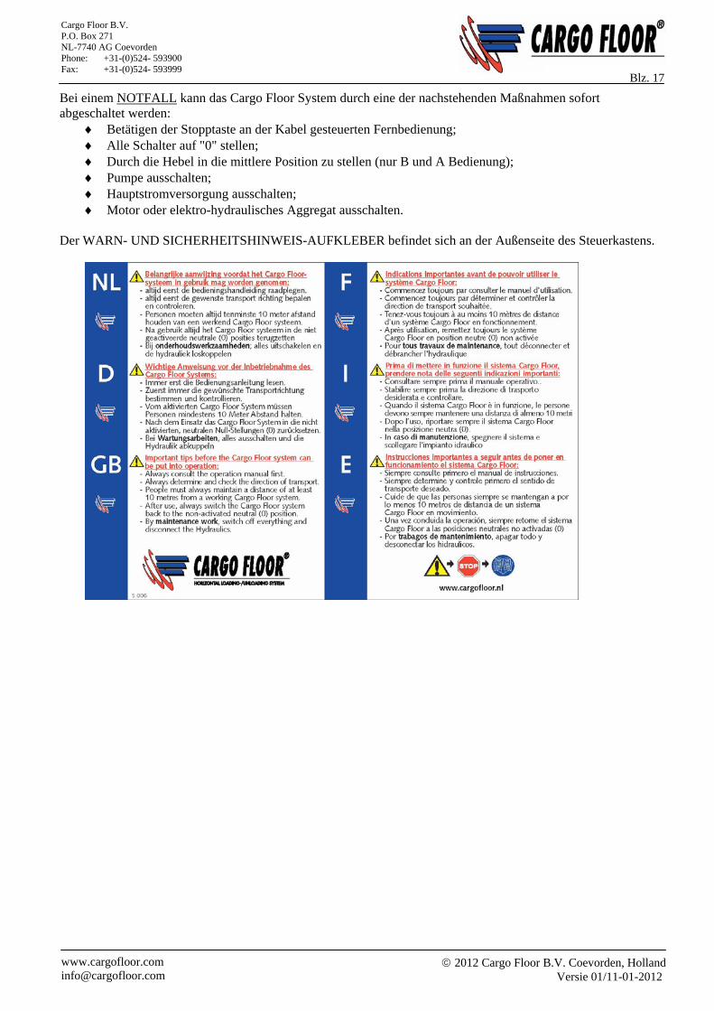
Der WARN- UND SICHERHEITSHINWEIS-AUFKLEBER befindet sich an der Außenseite des Steuerkastens.
2012 Cargo Floor B.V. Coevorden, Holland
Versie 01/11-01-2012 www.cargofloor.com [email protected]
Cargo Floor B.V. P.O. Box 271 NL-7740 AG Coevorden Phone: +31-(0)524- 593900 Fax: +31-(0)524- 593999
Blz. 18
FIG. / ABB. 1A
FIG. / ABB. 2
FIG. / ABB. 1B
2012 Cargo Floor B.V. Coevorden, Holland
Versie 01/11-01-2012 www.cargofloor.com [email protected]
Cargo Floor B.V. P.O. Box 271 NL-7740 AG Coevorden Phone: +31-(0)524- 593900 Fax: +31-(0)524- 593999
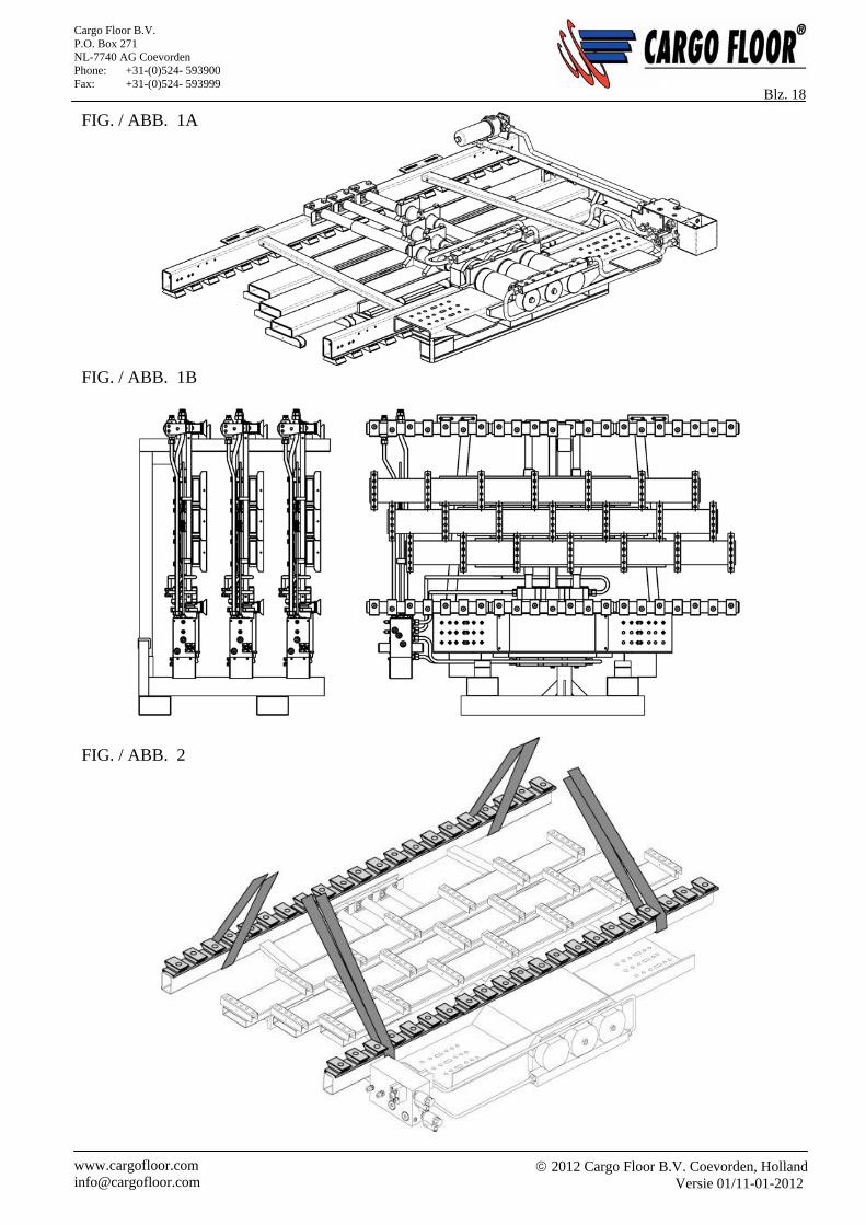
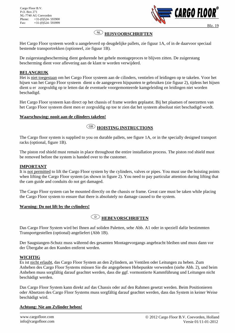
Blz. 19 NL HIJSVOORSCHRIFTEN
Het Cargo Floor systeem wordt u aangeleverd op deugdelijke pallets, zie figuur 1A, of in de daarvoor speciaal bestemde transportrekken (optioneel, zie figuur 1B). De zuigerstangbescherming dient gedurende het gehele montageproces te blijven zitten. De zuigerstang bescherming dient voor aflevering aan de klant te worden verwijderd. BELANGRIJK Het is niet toegestaan om het Cargo Floor systeem aan de cilinders, ventielen of leidingen op te takelen. Voor het hijsen van het Cargo Floor systeem dient u de aangegeven hijspunten te gebruiken (zie figuur 2), tijdens het hijsen dient u er zorgvuldig op te letten dat de eventuele voorgemonteerde kamgeleiding en leidingen niet worden beschadigd. Het Cargo Floor systeem kan direct op het chassis of frame worden geplaatst. Bij het plaatsen of neerzetten van het Cargo Floor systeem dient men er zorgvuldig op toe te zien dat het systeem absoluut niet beschadigd wordt. Waarschuwing: nooit aan de cilinders takelen!
GB HOISTING INSTRUCTIONS The Cargo floor system is supplied to you on durable pallets, see figure 1A, or in the specially designed transport racks (optional, figure 1B). The piston rod shield must remain in place throughout the entire installation process. The piston rod shield must be removed before the system is handed over to the customer. IMPORTANT It is not permitted to lift the Cargo Floor system by the cylinders, valves or pipes. You must use the hoisting points when lifting the Cargo Floor system (as shown in figure 2). You need to pay particular attention during lifting that the cam guide and conduits do not get damaged. The Cargo Floor system can be mounted directly on the chassis or frame. Great care must be taken while placing the Cargo Floor system to ensure that there is absolutely no damage caused to the system. Warning: Do not lift by the cylinders!
D HEBEVORSCHRIFTEN
Das Cargo Floor System wird bei Ihnen auf soliden Paletten, sehe Abb. A1 oder in speziell dafür bestimmten Transportgestellen (optional) angeliefert (Abb 1B). Der Saugstangen-Schutz muss während des gesamten Montagevorgangs angebracht bleiben und muss dann vor der Übergabe an den Kunden entfernt werden. WICHTIG Es ist nicht erlaubt, das Cargo Floor System an den Zylindern, an Ventilen oder Leitungen zu heben. Zum Anheben des Cargo Floor Systems müssen Sie die angegebenen Hebepunkte verwenden (siehe Abb. 2), und beim Anheben muss sorgfältig darauf geachtet werden, dass die ggf. vormontierte Kammführung und Leitungen nicht beschädigt werden. Das Cargo Floor System kann direkt auf das Chassis oder auf den Rahmen gesetzt werden. Beim Positionieren oder Absetzen des Cargo Floor Systems muss sorgfältig darauf geachtet werden, dass das System in keiner Weise beschädigt wird. Achtung: Nie am Zylinder heben!
2012 Cargo Floor B.V. Coevorden, Holland
Versie 01/11-01-2012 www.cargofloor.com [email protected]
Cargo Floor B.V. P.O. Box 271 NL-7740 AG Coevorden Phone: +31-(0)524- 593900 Fax: +31-(0)524- 593999
Blz. 20
FIG. / ABB. 3
2012 Cargo Floor B.V. Coevorden, Holland
Versie 01/11-01-2012 www.cargofloor.com [email protected]
Cargo Floor B.V. P.O. Box 271 NL-7740 AG Coevorden Phone: +31-(0)524- 593900 Fax: +31-(0)524- 593999
Blz. 21 NL HET CHASSIS
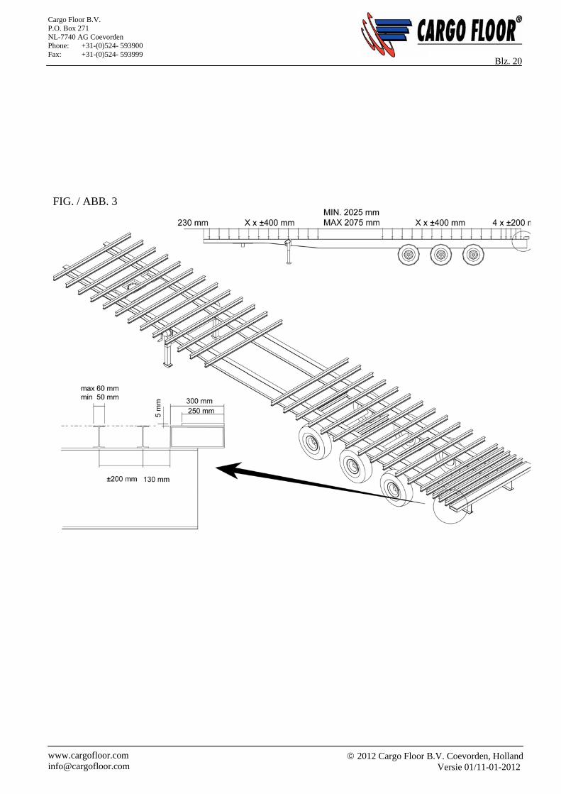
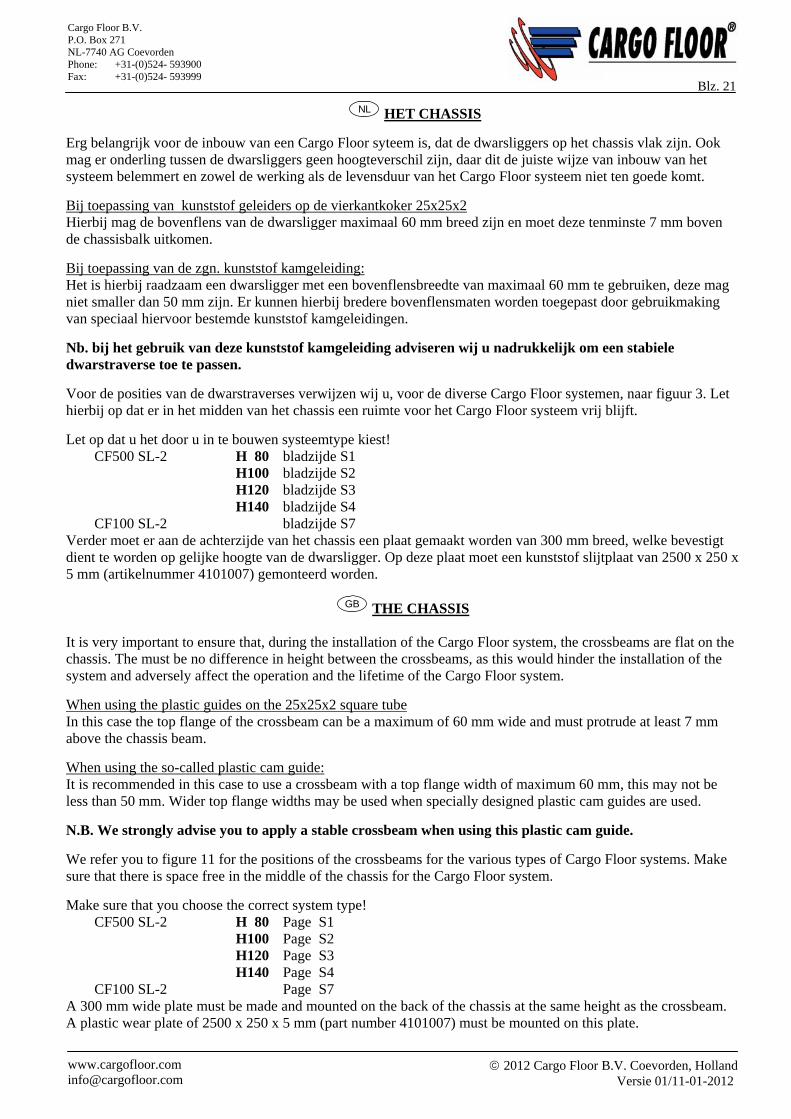
Erg belangrijk voor de inbouw van een Cargo Floor syteem is, dat de dwarsliggers op het chassis vlak zijn. Ook mag er onderling tussen de dwarsliggers geen hoogteverschil zijn, daar dit de juiste wijze van inbouw van het systeem belemmert en zowel de werking als de levensduur van het Cargo Floor systeem niet ten goede komt.
Bij toepassing van kunststof geleiders op de vierkantkoker 25x25x2 Hierbij mag de bovenflens van de dwarsligger maximaal 60 mm breed zijn en moet deze tenminste 7 mm boven de chassisbalk uitkomen.
Bij toepassing van de zgn. kunststof kamgeleiding: Het is hierbij raadzaam een dwarsligger met een bovenflensbreedte van maximaal 60 mm te gebruiken, deze mag niet smaller dan 50 mm zijn. Er kunnen hierbij bredere bovenflensmaten worden toegepast door gebruikmaking van speciaal hiervoor bestemde kunststof kamgeleidingen.
Nb. bij het gebruik van deze kunststof kamgeleiding adviseren wij u nadrukkelijk om een stabiele dwarstraverse toe te passen.
Voor de posities van de dwarstraverses verwijzen wij u, voor de diverse Cargo Floor systemen, naar figuur 3. Let hierbij op dat er in het midden van het chassis een ruimte voor het Cargo Floor systeem vrij blijft.
Let op dat u het door u in te bouwen systeemtype kiest! CF500 SL-2 H 80 bladzijde S1 H100 bladzijde S2 H120 bladzijde S3 H140 bladzijde S4 CF100 SL-2 bladzijde S7
Verder moet er aan de achterzijde van het chassis een plaat gemaakt worden van 300 mm breed, welke bevestigt dient te worden op gelijke hoogte van de dwarsligger. Op deze plaat moet een kunststof slijtplaat van 2500 x 250 x 5 mm (artikelnummer 4101007) gemonteerd worden.
GB THE CHASSIS It is very important to ensure that, during the installation of the Cargo Floor system, the crossbeams are flat on the chassis. The must be no difference in height between the crossbeams, as this would hinder the installation of the system and adversely affect the operation and the lifetime of the Cargo Floor system.
When using the plastic guides on the 25x25x2 square tube In this case the top flange of the crossbeam can be a maximum of 60 mm wide and must protrude at least 7 mm above the chassis beam.
When using the so-called plastic cam guide: It is recommended in this case to use a crossbeam with a top flange width of maximum 60 mm, this may not be less than 50 mm. Wider top flange widths may be used when specially designed plastic cam guides are used.
N.B. We strongly advise you to apply a stable crossbeam when using this plastic cam guide.
We refer you to figure 11 for the positions of the crossbeams for the various types of Cargo Floor systems. Make sure that there is space free in the middle of the chassis for the Cargo Floor system.
Make sure that you choose the correct system type! CF500 SL-2 H 80 Page S1 H100 Page S2 H120 Page S3 H140 Page S4 CF100 SL-2 Page S7
A 300 mm wide plate must be made and mounted on the back of the chassis at the same height as the crossbeam. A plastic wear plate of 2500 x 250 x 5 mm (part number 4101007) must be mounted on this plate.
2012 Cargo Floor B.V. Coevorden, Holland
Versie 01/11-01-2012 www.cargofloor.com [email protected]
Cargo Floor B.V. P.O. Box 271 NL-7740 AG Coevorden Phone: +31-(0)524- 593900 Fax: +31-(0)524- 593999
Blz. 22
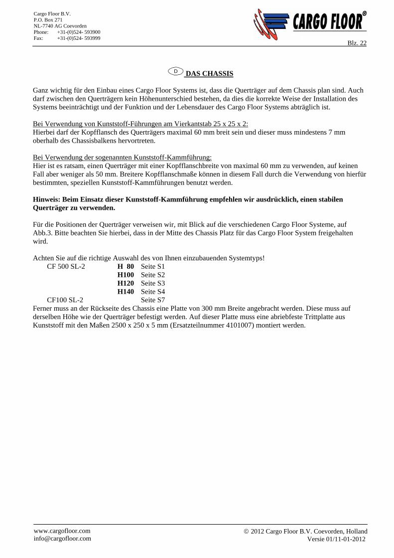
D DAS CHASSIS Ganz wichtig für den Einbau eines Cargo Floor Systems ist, dass die Querträger auf dem Chassis plan sind. Auch darf zwischen den Querträgern kein Höhenunterschied bestehen, da dies die korrekte Weise der Installation des Systems beeinträchtigt und der Funktion und der Lebensdauer des Cargo Floor Systems abträglich ist. Bei Verwendung von Kunststoff-Führungen am Vierkantstab 25 x 25 x 2: Hierbei darf der Kopfflansch des Querträgers maximal 60 mm breit sein und dieser muss mindestens 7 mm oberhalb des Chassisbalkens hervortreten. Bei Verwendung der sogenannten Kunststoff-Kammführung: Hier ist es ratsam, einen Querträger mit einer Kopfflanschbreite von maximal 60 mm zu verwenden, auf keinen Fall aber weniger als 50 mm. Breitere Kopfflanschmaße können in diesem Fall durch die Verwendung von hierfür bestimmten, speziellen Kunststoff-Kammführungen benutzt werden. Hinweis: Beim Einsatz dieser Kunststoff-Kammführung empfehlen wir ausdrücklich, einen stabilen Querträger zu verwenden. Für die Positionen der Querträger verweisen wir, mit Blick auf die verschiedenen Cargo Floor Systeme, auf Abb.3. Bitte beachten Sie hierbei, dass in der Mitte des Chassis Platz für das Cargo Floor System freigehalten wird. Achten Sie auf die richtige Auswahl des von Ihnen einzubauenden Systemtyps!
CF 500 SL-2 H 80 Seite S1 H100 Seite S2 H120 Seite S3 H140 Seite S4 CF100 SL-2 Seite S7
Ferner muss an der Rückseite des Chassis eine Platte von 300 mm Breite angebracht werden. Diese muss auf derselben Höhe wie der Querträger befestigt werden. Auf dieser Platte muss eine abriebfeste Trittplatte aus Kunststoff mit den Maßen 2500 x 250 x 5 mm (Ersatzteilnummer 4101007) montiert werden.
2012 Cargo Floor B.V. Coevorden, Holland
Versie 01/11-01-2012 www.cargofloor.com [email protected]
Cargo Floor B.V. P.O. Box 271 NL-7740 AG Coevorden Phone: +31-(0)524- 593900 Fax: +31-(0)524- 593999
Blz. 23 FIG. / ABB. 4 A
FIG. / ABB. 4B
A
D
C
B
Detail A-B-C-D
2012 Cargo Floor B.V. Coevorden, Holland
Versie 01/11-01-2012 www.cargofloor.com [email protected]
Cargo Floor B.V. P.O. Box 271 NL-7740 AG Coevorden Phone: +31-(0)524- 593900 Fax: +31-(0)524- 593999
Blz. 24
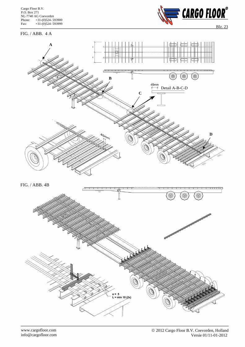
NL MONTAGE VAN DE VIERKANTE KOKERS (25x25x2) Er dient in het midden van de dwarstraversen, in de exacte centerlijn, een vierkante koker over de gehele lengte te worden aangebracht. Deze vierkante koker wordt gebruikt als geleiding cq. referentie van de drie meegeleverde lasmallen, zie figuur 4A. De vierkante kokers dienen deugdelijk aan elke dwarstraverse, tweezijdig, te worden vastgelast met een las van tenminste 10 mm lang (zie figuur 4B). Let hierbij op dat de begin- /eindpositie van de kokers juist zijn, dit in verband met de benodigde oversteek voor een juiste montage van de kunststof geleiders (TWISTERS, artikelnummer 4107002). Het gebruik van de meegeleverde lasmallen (3 stuks) Alle vierkante kokers dienen eenzijdig in dezelfde richting te worden aangedrukt in de lasmal. De lasmal dient stevig geklemd te worden op de dwarstraverse, zodat er geen hoogteverschillen tussen de vierkante kokers ontstaan. Voor plaatsing en gebruik van de lasmallen, zie figuur 4B.
GB MOUNTING THE (25X25X2) SQUARE TUBES A square tube needs to be installed, over the full length and along the exact centre line of each of the crossbeams. These square tubes are used as guides and as references for the three (supplied) welding jigs, see figure 4A. The square tubes need to be securely welded on both sides to each crossbeam with a weld of at least 10 mm length (as shown in figure 4B) Take care while doing this to ensure that the start and end positions of the tube are correct, with the necessary projection for the correct mounting of the plastic guides (TWISTERS, articlenumber 4107002). Use of the supplied welding jigs (3 pieces) All square tubes need to be pressed into the welding jig on one side and in the same direction. The welding jig needs to be clamped securely onto the crossbeam, so that the square tubes are all at exactly the same height. See figure 4B for the positioning and use of the welding jigs.
D MONTAGE DER VIERKANTROHRE (25 x 25 x 2) In der Mitte des Querträgers, exakt mittig gefluchtet, muss ein Vierkantstab über die gesamte Länge angebracht werden. Dieser Vierkantstab wird als Führung bzw. als Referenz für drei mitgelieferte Schweißlehren verwendet, sehe Abb. 4A. Die Vierkantrohre müssen ordnungsgemäß an jedem Querträger, zweiseitig, mit einer Schweißnaht von mindestens 10 cm Länge festgeschweißt werden (siehe Abb. 4B). Achten Sie hierbei auf die richtige Anfangs- und Endposition der Rohre, dies im Zusammenhang mit dem erforderlichen Überstand zur korrekten Montage der Kunststoff-Führungen (TWISTERS, Ersatzteilnummer 4107002). Die Verwendung der mitgelieferten Schweißlehren (3 Stück) Alle Vierkantrohre müssen einseitig in dieselbe Richtung in die Schweißlehre gedrückt werden. Die Schweißlehre muss stabil an den Querträger geklemmt werden, damit kein Höhenunterschied zwischen den Vierkantrohren entsteht. Für die Positionierung und die Verwendung der Schweißlehren siehe Abb 4B.
2012 Cargo Floor B.V. Coevorden, Holland
Versie 01/11-01-2012 www.cargofloor.com [email protected]
Cargo Floor B.V. P.O. Box 271 NL-7740 AG Coevorden Phone: +31-(0)524- 593900 Fax: +31-(0)524- 593999
Blz. 25
FIG. / ABB. 5
2012 Cargo Floor B.V. Coevorden, Holland
Versie 01/11-01-2012 www.cargofloor.com [email protected]
Cargo Floor B.V. P.O. Box 271 NL-7740 AG Coevorden Phone: +31-(0)524- 593900 Fax: +31-(0)524- 593999
Blz. 26
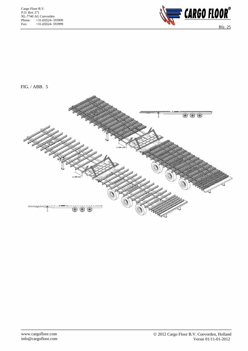
NL PLAATSING VAN HET SYSTEEM Alvorens het Cargo Floor systeem te plaatsen, dienen de hijsvoorschriften, zoals vermeld op bladzijde 9 en 10, in acht te worden genomen. Het Cargo Floor systeem kan nu in de daarvoor bestemde opening op het chassis / frame worden gelegd (zie figuur 5), waarbij de cilinderhuizen altijd in de losrichting moeten wijzen. Zie chassistekening op bladzijde C1 / C2.
GB POSITIONING THE SYSTEM
The hoisting procedures, as described on page 9 and 10, need to be studied before placing the Cargo Floor system. The Cargo Floor system can now be laid in the appropriate opening on the chassis / frame (see figure 5), noting that the cylinder housings must always point in the unloading direction. See chassis drawing on page C1 / C2.
D AUFSTELLEN DES SYSTEMS Vor dem Aufstellen des Cargo Floor Systems müssen die Hebevorschriften durchgegangen werden (siehe Seite 9 und 10). Das Cargo Floor System kann jetzt in die dafür bestimmte Öffnung auf das Chassis bzw. den Rahmen gesetzt werden (sehe Abb. 5), wobei die Zylindergehäuse immer in Entladerichtung weisen müssen. Siehe Chassiszeichnung auf Seite C1 / C2.
2012 Cargo Floor B.V. Coevorden, Holland
Versie 01/11-01-2012 www.cargofloor.com [email protected]
Cargo Floor B.V. P.O. Box 271 NL-7740 AG Coevorden Phone: +31-(0)524- 593900 Fax: +31-(0)524- 593999
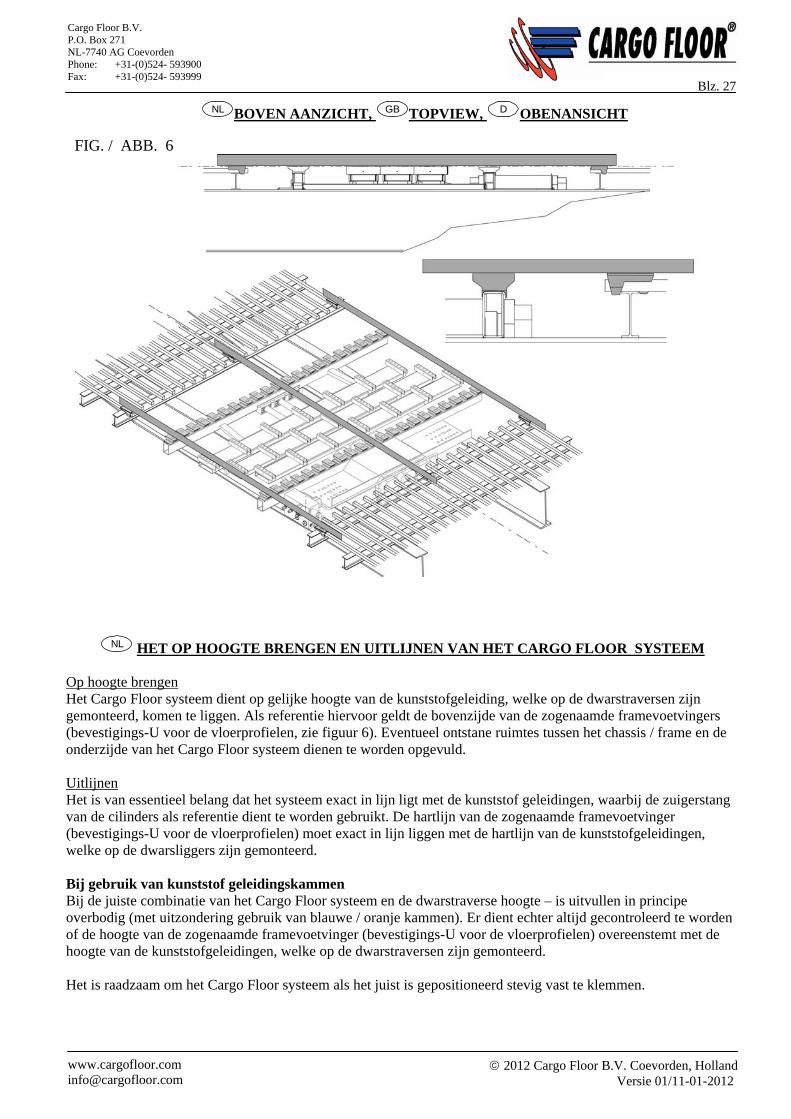
Blz. 27 NL BOVEN AANZICHT, GB TOPVIEW, D OBENANSICHT
NL HET OP HOOGTE BRENGEN EN UITLIJNEN VAN HET CARGO FLOOR SYSTEEM
Op hoogte brengen Het Cargo Floor systeem dient op gelijke hoogte van de kunststofgeleiding, welke op de dwarstraversen zijn gemonteerd, komen te liggen. Als referentie hiervoor geldt de bovenzijde van de zogenaamde framevoetvingers (bevestigings-U voor de vloerprofielen, zie figuur 6). Eventueel ontstane ruimtes tussen het chassis / frame en de onderzijde van het Cargo Floor systeem dienen te worden opgevuld. Uitlijnen Het is van essentieel belang dat het systeem exact in lijn ligt met de kunststof geleidingen, waarbij de zuigerstang van de cilinders als referentie dient te worden gebruikt. De hartlijn van de zogenaamde framevoetvinger (bevestigings-U voor de vloerprofielen) moet exact in lijn liggen met de hartlijn van de kunststofgeleidingen, welke op de dwarsliggers zijn gemonteerd. Bij gebruik van kunststof geleidingskammen Bij de juiste combinatie van het Cargo Floor systeem en de dwarstraverse hoogte – is uitvullen in principe overbodig (met uitzondering gebruik van blauwe / oranje kammen). Er dient echter altijd gecontroleerd te worden of de hoogte van de zogenaamde framevoetvinger (bevestigings-U voor de vloerprofielen) overeenstemt met de hoogte van de kunststofgeleidingen, welke op de dwarstraversen zijn gemonteerd. Het is raadzaam om het Cargo Floor systeem als het juist is gepositioneerd stevig vast te klemmen.
FIG. / ABB. 6
2012 Cargo Floor B.V. Coevorden, Holland
Versie 01/11-01-2012 www.cargofloor.com [email protected]
Cargo Floor B.V. P.O. Box 271 NL-7740 AG Coevorden Phone: +31-(0)524- 593900 Fax: +31-(0)524- 593999
Blz. 28
GB HEIGHT ADJUSTMENT AND ALIGNMENT OF THE CARGO FLOOR SYSTEM
Height adjustment The Cargo Floor system needs to be at the same height as the plastic guides that are mounted on the crossbeams. The top of the so-called frame foot fingers (U-fasteners for the floor profiles, see figure 6) is the reference. Any extra spaces that have been created between the chassis / frame and the underside of the Cargo Floor system should be filled. Alignment It is extremely important that the system is exactly lined up with the plastic guides. The piston rod of the cylinders is used as reference for this. The centre line of the so-called frame foot finger (U-fastener for the floor profiles) must be exactly in line with the centre line of the plastic guides mounted on the crossbeams. When using the plastic guides Padding is not necessary when the correct combination of Cargo Floor height and crossbeam height is realised (except when blue / orange cams are utilised). You really need to check that the height of the so-called frame foot finger (U-fastener for the floor profiles) lines up with the plastic guides mounted on the crossbeams. It is advisable to clamp the Cargo Floor system securely once it is correctly positioned.
D HÖHE DES CARGO FLOOR SYSTEMS ANPASSEN UND SYSTEM AUSRICHTEN
Höhe anpassen Das Cargo Floor System muss auf gleicher Höhe wie die Kunststoff-Führung positioniert werden, welche auf den Querträgern montiert sind. Als Referenz dient hierfür die Oberseite der sogenannten Rahmen-Stützausleger (Befestigungs-U für die Bodenprofile, sehe Abb. 6). Eventuell entstandene Räume zwischen dem Chassis bzw. dem Rahmen und der Unterseite des Cargo Floor Systems müssen ausgefüllt werden. Ausrichten Es ist von größter Wichtigkeit, dass das System mit den Kunststoff-Führungen exakt gefluchtet ist, wobei die Saugstange der Zylinder als Referenz benutzt werden muss. Die Achse der sogenannten Rahmen-Stützausleger (Befestigungs-U für die Bodenprofile) muss exakt mit der Achse der Kunststoff-Führungen gefluchtet sein, welche auf den Querträgern montiert sind. Bei Verwendung der kunststoff Gleitkammen Bei der ordnungsgemäßen Kombination des Cargo Floor Systems und der Höhe des Querträgers ist das Ausfüllen im Prinzip überflüssig (Ausnahme: bei Verwendung von blauen / orangefarbenen Kämmen). Es muss allerdings immer geprüft werden, ob die Höhe der sogenannten Rahmen-Stützausleger (Befestigungs-U für die Bodenprofile) mit der Höhe der Kunststoff-Führungen übereinstimmt, welche auf den Querträgern montiert sind. Es empfiehlt sich, das Cargo Floor System nach erfolgter Ausrichtung stabil festzuklemmen.
2012 Cargo Floor B.V. Coevorden, Holland
Versie 01/11-01-2012 www.cargofloor.com [email protected]
Cargo Floor B.V. P.O. Box 271 NL-7740 AG Coevorden Phone: +31-(0)524- 593900 Fax: +31-(0)524- 593999
Blz. 29
FIG . / ABB. 8
FIG. / ABB. 7
2012 Cargo Floor B.V. Coevorden, Holland
Versie 01/11-01-2012 www.cargofloor.com [email protected]
Cargo Floor B.V. P.O. Box 271 NL-7740 AG Coevorden Phone: +31-(0)524- 593900 Fax: +31-(0)524- 593999
Blz. 30
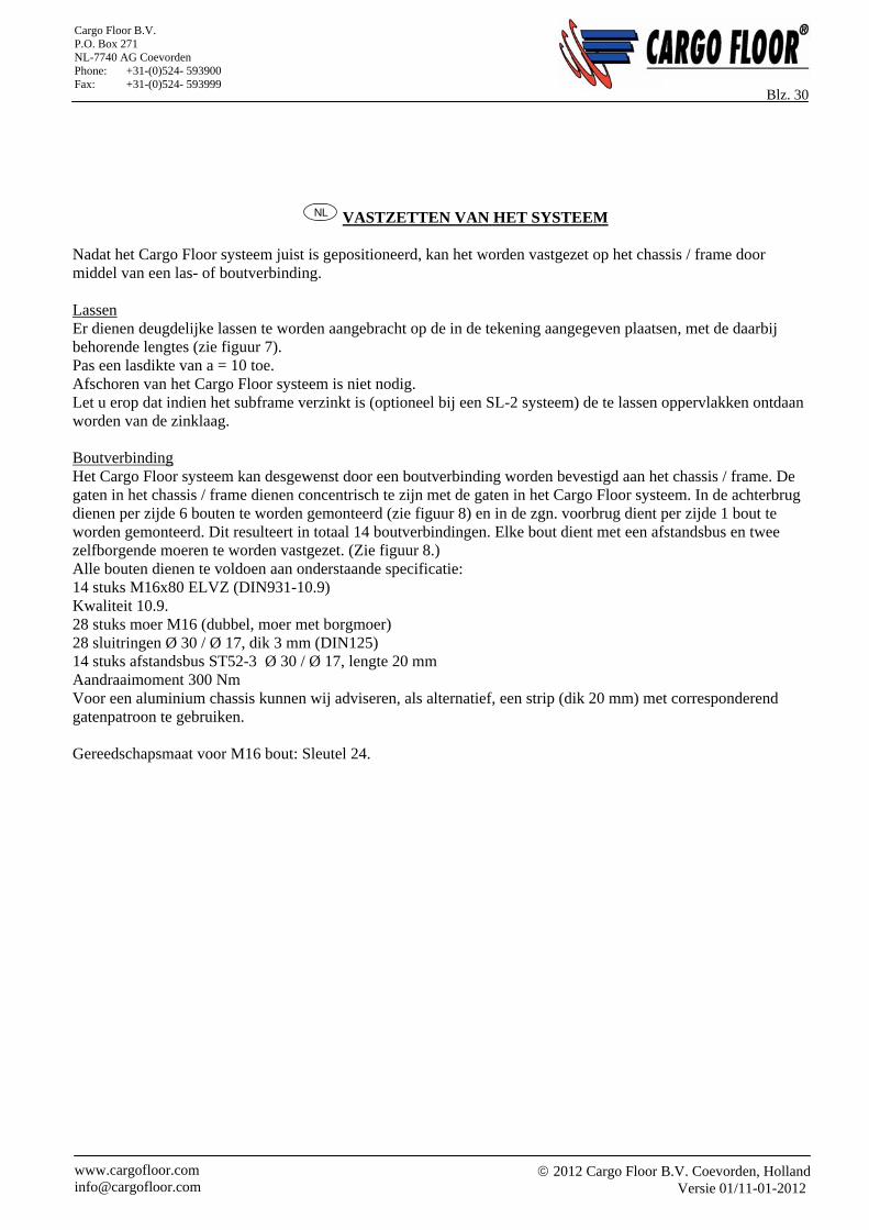
NL VASTZETTEN VAN HET SYSTEEM
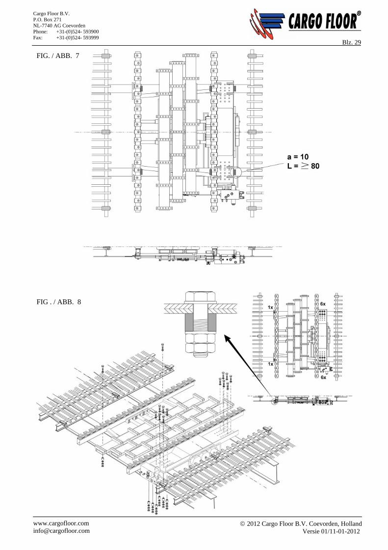
Nadat het Cargo Floor systeem juist is gepositioneerd, kan het worden vastgezet op het chassis / frame door middel van een las- of boutverbinding. Lassen Er dienen deugdelijke lassen te worden aangebracht op de in de tekening aangegeven plaatsen, met de daarbij behorende lengtes (zie figuur 7). Pas een lasdikte van a = 10 toe. Afschoren van het Cargo Floor systeem is niet nodig. Let u erop dat indien het subframe verzinkt is (optioneel bij een SL-2 systeem) de te lassen oppervlakken ontdaan worden van de zinklaag. Boutverbinding Het Cargo Floor systeem kan desgewenst door een boutverbinding worden bevestigd aan het chassis / frame. De gaten in het chassis / frame dienen concentrisch te zijn met de gaten in het Cargo Floor systeem. In de achterbrug dienen per zijde 6 bouten te worden gemonteerd (zie figuur 8) en in de zgn. voorbrug dient per zijde 1 bout te worden gemonteerd. Dit resulteert in totaal 14 boutverbindingen. Elke bout dient met een afstandsbus en twee zelfborgende moeren te worden vastgezet. (Zie figuur 8.) Alle bouten dienen te voldoen aan onderstaande specificatie: 14 stuks M16x80 ELVZ (DIN931-10.9) Kwaliteit 10.9. 28 stuks moer M16 (dubbel, moer met borgmoer) 28 sluitringen Ø 30 / Ø 17, dik 3 mm (DIN125) 14 stuks afstandsbus ST52-3 Ø 30 / Ø 17, lengte 20 mm Aandraaimoment 300 Nm Voor een aluminium chassis kunnen wij adviseren, als alternatief, een strip (dik 20 mm) met corresponderend gatenpatroon te gebruiken. Gereedschapsmaat voor M16 bout: Sleutel 24.
2012 Cargo Floor B.V. Coevorden, Holland
Versie 01/11-01-2012 www.cargofloor.com [email protected]
Cargo Floor B.V. P.O. Box 271 NL-7740 AG Coevorden Phone: +31-(0)524- 593900 Fax: +31-(0)524- 593999
Blz. 31
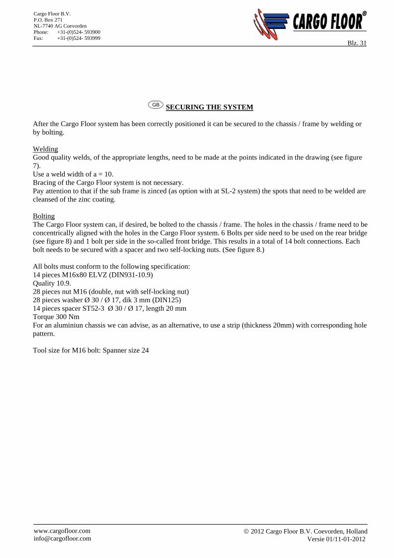
GB SECURING THE SYSTEM After the Cargo Floor system has been correctly positioned it can be secured to the chassis / frame by welding or by bolting. Welding Good quality welds, of the appropriate lengths, need to be made at the points indicated in the drawing (see figure 7). Use a weld width of a = 10. Bracing of the Cargo Floor system is not necessary. Pay attention to that if the sub frame is zinced (as option with at SL-2 system) the spots that need to be welded are cleansed of the zinc coating. Bolting The Cargo Floor system can, if desired, be bolted to the chassis / frame. The holes in the chassis / frame need to be concentrically aligned with the holes in the Cargo Floor system. 6 Bolts per side need to be used on the rear bridge (see figure 8) and 1 bolt per side in the so-called front bridge. This results in a total of 14 bolt connections. Each bolt needs to be secured with a spacer and two self-locking nuts. (See figure 8.) All bolts must conform to the following specification: 14 pieces M16x80 ELVZ (DIN931-10.9) Quality 10.9. 28 pieces nut M16 (double, nut with self-locking nut) 28 pieces washer Ø 30 / Ø 17, dik 3 mm (DIN125) 14 pieces spacer ST52-3 Ø 30 / Ø 17, length 20 mm Torque 300 Nm For an aluminiun chassis we can advise, as an alternative, to use a strip (thickness 20mm) with corresponding hole pattern. Tool size for M16 bolt: Spanner size 24
2012 Cargo Floor B.V. Coevorden, Holland
Versie 01/11-01-2012 www.cargofloor.com [email protected]
Cargo Floor B.V. P.O. Box 271 NL-7740 AG Coevorden Phone: +31-(0)524- 593900 Fax: +31-(0)524- 593999
Blz. 32
D BEFESTIGUNG DES SYSTEMS
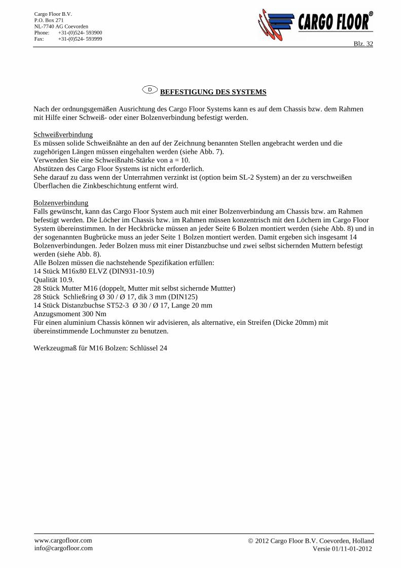
Nach der ordnungsgemäßen Ausrichtung des Cargo Floor Systems kann es auf dem Chassis bzw. dem Rahmen mit Hilfe einer Schweiß- oder einer Bolzenverbindung befestigt werden. Schweißverbindung Es müssen solide Schweißnähte an den auf der Zeichnung benannten Stellen angebracht werden und die zugehörigen Längen müssen eingehalten werden (siehe Abb. 7). Verwenden Sie eine Schweißnaht-Stärke von a = 10. Abstützen des Cargo Floor Systems ist nicht erforderlich. Sehe darauf zu dass wenn der Unterrahmen verzinkt ist (option beim SL-2 System) an der zu verschweißen Überflachen die Zinkbeschichtung entfernt wird. Bolzenverbindung Falls gewünscht, kann das Cargo Floor System auch mit einer Bolzenverbindung am Chassis bzw. am Rahmen befestigt werden. Die Löcher im Chassis bzw. im Rahmen müssen konzentrisch mit den Löchern im Cargo Floor System übereinstimmen. In der Heckbrücke müssen an jeder Seite 6 Bolzen montiert werden (siehe Abb. 8) und in der sogenannten Bugbrücke muss an jeder Seite 1 Bolzen montiert werden. Damit ergeben sich insgesamt 14 Bolzenverbindungen. Jeder Bolzen muss mit einer Distanzbuchse und zwei selbst sichernden Muttern befestigt werden (siehe Abb. 8). Alle Bolzen müssen die nachstehende Spezifikation erfüllen: 14 Stück M16x80 ELVZ (DIN931-10.9) Qualität 10.9. 28 Stück Mutter M16 (doppelt, Mutter mit selbst sichernde Muttter) 28 Stück Schließring Ø 30 / Ø 17, dik 3 mm (DIN125) 14 Stück Distanzbuchse ST52-3 Ø 30 / Ø 17, Lange 20 mm Anzugsmoment 300 Nm Für einen aluminium Chassis können wir advisieren, als alternative, ein Streifen (Dicke 20mm) mit übereinstimmende Lochmunster zu benutzen. Werkzeugmaß für M16 Bolzen: Schlüssel 24
2012 Cargo Floor B.V. Coevorden, Holland
Versie 01/11-01-2012 www.cargofloor.com [email protected]
Cargo Floor B.V. P.O. Box 271 NL-7740 AG Coevorden Phone: +31-(0)524- 593900 Fax: +31-(0)524- 593999
Blz. 33
NL HET AFSCHOREN VAN DE ZIJWANDEN
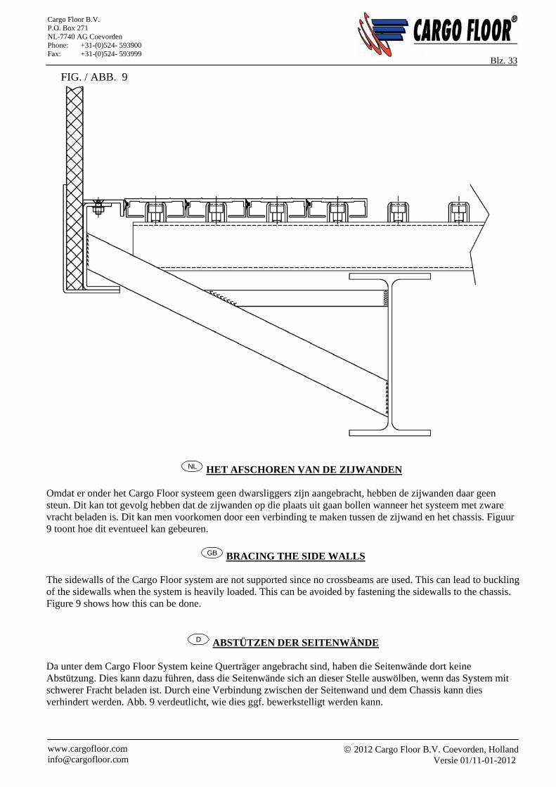
Omdat er onder het Cargo Floor systeem geen dwarsliggers zijn aangebracht, hebben de zijwanden daar geen steun. Dit kan tot gevolg hebben dat de zijwanden op die plaats uit gaan bollen wanneer het systeem met zware vracht beladen is. Dit kan men voorkomen door een verbinding te maken tussen de zijwand en het chassis. Figuur 9 toont hoe dit eventueel kan gebeuren.
GB BRACING THE SIDE WALLS The sidewalls of the Cargo Floor system are not supported since no crossbeams are used. This can lead to buckling of the sidewalls when the system is heavily loaded. This can be avoided by fastening the sidewalls to the chassis. Figure 9 shows how this can be done.
D ABSTÜTZEN DER SEITENWÄNDE Da unter dem Cargo Floor System keine Querträger angebracht sind, haben die Seitenwände dort keine Abstützung. Dies kann dazu führen, dass die Seitenwände sich an dieser Stelle auswölben, wenn das System mit schwerer Fracht beladen ist. Durch eine Verbindung zwischen der Seitenwand und dem Chassis kann dies verhindert werden. Abb. 9 verdeutlicht, wie dies ggf. bewerkstelligt werden kann.
FIG. / ABB. 9
2012 Cargo Floor B.V. Coevorden, Holland
Versie 01/11-01-2012 www.cargofloor.com [email protected]
Cargo Floor B.V. P.O. Box 271 NL-7740 AG Coevorden Phone: +31-(0)524- 593900 Fax: +31-(0)524- 593999
Blz. 34
FIG. / ABB. 11
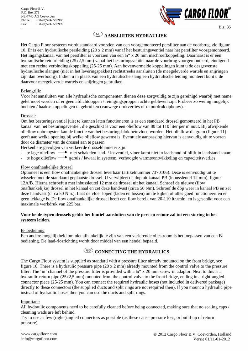
De arcering geeft het bereik van de standaard drossel aan. The shading points out the reach of the standard choke. Der Schraffierung gibt der Bereich der standard drossel an
FIG. / ABB. 12A
DIN 906-5.8-3/4” Af werk – Ex works – Ab Werk Ø6,5 mm
FIG. / ABB. 12B
FIG. / ABB. 10
2012 Cargo Floor B.V. Coevorden, Holland
Versie 01/11-01-2012 www.cargofloor.com [email protected]
Cargo Floor B.V. P.O. Box 271 NL-7740 AG Coevorden Phone: +31-(0)524- 593900 Fax: +31-(0)524- 593999
Blz. 35 NL AANSLUITEN HYDRAULIEK
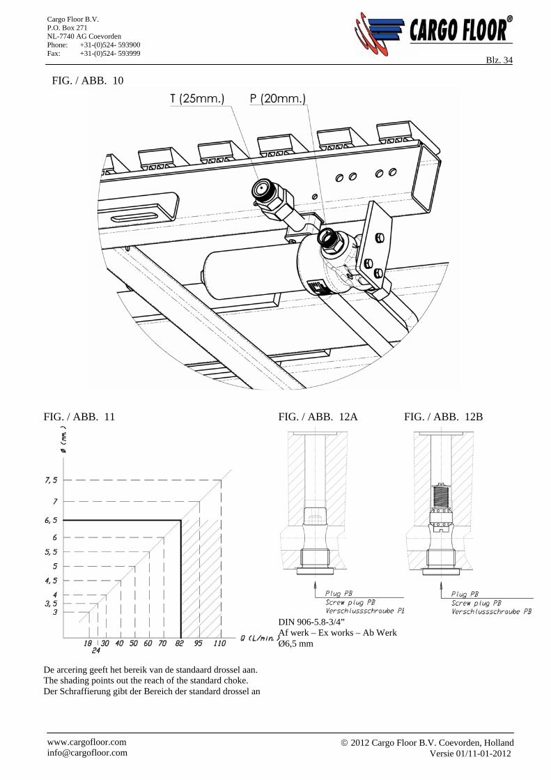
Het Cargo Floor systeem wordt standaard voorzien van een voorgemonteerd persfilter aan de voorbrug, zie figuur 10. Er is een hydraulische persleiding (20 x 2 mm) vanaf het besturingsventiel naar het persfilter voorgemonteerd. Het ingangskanaal van het persfilter is voorzien van een ¾“ x 20 mm inschroefkoppeling. Daarnaast is er een hydraulische retourleiding (25x2,5 mm) vanaf het besturingsventiel naar de voorbrug voorgemonteerd, eindigend met een rechte verbindingskoppeling (25-25 mm). Aan bovenvermelde koppelingen kunt u de desgewenste hydraulische slangen (niet in het leveringspakket) rechtstreeks aansluiten (de meegeleverde wartels en snijringen zijn dan overbodig). Indien u in plaats van een hydraulische slang een hydraulische leiding monteert kunt u de daarvoor meegeleverde wartels en snijringen gebruiken.
Belangrijk: Voor het aansluiten van alle hydraulische componenten dienen deze zorgvuldig te zijn gereinigd waarbij met name gelet moet worden of er geen afdichtdoppen / reinigingsproppen achtergebleven zijn. Probeer zo weinig mogelijk bochten / haakse koppelingen te gebruiken (vanwege drukverlies of retourdruk opbouw).
Drossel: Om het besturingsventiel juist te kunnen laten functioneren is er een standaard drossel gemonteerd in het PB kanaal van het besturingsventiel, die geschikt is voor een olieflow van 80 tot 110 liter per minuut. Bij afwijkende olieflow opbrengsten kan de functie van het besturingsblok beïnvloed worden. Het olieflow diagram (figuur 11) geeft aan welke opening bij welke olieflow gewenst is. Eventuele aanpassing hiervan is eenvoudig uit te voeren door de diameter van de drossel aan te passen. Herkenbare gevolgen van verkeerde drosseldiameter zijn: - te lage olieflow niet schakelen laad- / losventiel, vloer komt niet in laadstand of blijft in laadstand staan; - te hoge olieflow geruis / lawaai in systeem, verhoogde warmteontwikkeling en capaciteitsverlies.
Flow onafhankelijke drossel Optioneel is een flow onafhankelijke drossel leverbaar (artikelnummer 7370106). Deze is eenvoudig uit te wisselen met de standaard geplaatste drossel. U verwijdert de dop uit kanaal PB (inbussleutel 12 mm), figuur 12A/B. Hierna schroeft u met inbussleutel 12 mm de drossel uit het kanaal. Schroef de nieuwe (flow onafhankelijke) drossel in het kanaal en zet deze handvast (circa 50 Nm). Schroef de dop weer in kanaal PB en zet deze handvast (circa 50 Nm.). Laat de vloer lopen (laden en lossen) om te kijken of alles goed functioneert en er geen lekkage is. De flow onafhankelijke drossel heeft een flow bereik van 20-110 ltr./min. en is geschikt voor een maximale werkdruk van 225 bar. Voor beide typen drossels geldt: het foutief aansluiten van de pers en retour zal tot een storing in het systeem leiden. B- bediening Een andere mogelijkheid om niet afhankelijk te zijn van een varierende oliestroom is het toepassen van een B-bediening. De laad-/losrichting wordt door middel van een hendel bepaald.
GB CONNECTING THE HYDRAULICS
The Cargo Floor system is supplied as standard with a pressure filter already mounted on the front bridge, see figure 10. There is a hydraulic pressure pipe (20 x 2 mm) already mounted from the control valve to the pressure filter. The ‘in’ channel of the pressure filter is provided with a ¾“ x 20 mm screw-in adaptor. Next to this is a hydraulic return pipe (25x2,5 mm) mounted from the control valve to the front bridge, ending in a right-angled connector piece (25-25 mm). You can connect the required hydraulic hoses (not included in delivered package) directly to these connectors (the supplied ducts and split rings are not required then). If you mount a hydraulic pipe instead of hydraulic hoses then you can use the ducts and split rings.
Important: All hydraulic components need to be carefully cleaned before being connected, making sure that no sealing caps / cleaning wads are left behind. Try to use as few (right-)angled connectors as possible (as these cause pressure loss, or build-up of return pressure).
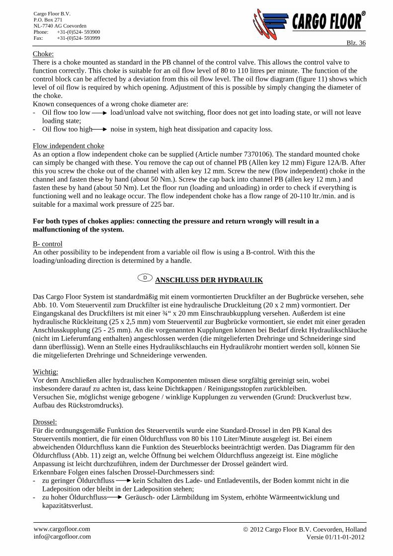
2012 Cargo Floor B.V. Coevorden, Holland
Versie 01/11-01-2012 www.cargofloor.com [email protected]
Cargo Floor B.V. P.O. Box 271 NL-7740 AG Coevorden Phone: +31-(0)524- 593900 Fax: +31-(0)524- 593999
Blz. 36 Choke: There is a choke mounted as standard in the PB channel of the control valve. This allows the control valve to function correctly. This choke is suitable for an oil flow level of 80 to 110 litres per minute. The function of the control block can be affected by a deviation from this oil flow level. The oil flow diagram (figure 11) shows which level of oil flow is required by which opening. Adjustment of this is possible by simply changing the diameter of the choke. Known consequences of a wrong choke diameter are: - Oil flow too low load/unload valve not switching, floor does not get into loading state, or will not leave
loading state; - Oil flow too high noise in system, high heat dissipation and capacity loss. Flow independent choke As an option a flow independent choke can be supplied (Article number 7370106). The standard mounted choke can simply be changed with these. You remove the cap out of channel PB (Allen key 12 mm) Figure 12A/B. After this you screw the choke out of the channel with allen key 12 mm. Screw the new (flow independent) choke in the channel and fasten these by hand (about 50 Nm.). Screw the cap back into channel PB (allen key 12 mm.) and fasten these by hand (about 50 Nm). Let the floor run (loading and unloading) in order to check if everything is functioning well and no leakage occur. The flow independent choke has a flow range of 20-110 ltr./min. and is suitable for a maximal work pressure of 225 bar. For both types of chokes applies: connecting the pressure and return wrongly will result in a malfunctioning of the system.
B- control An other possibility to be independent from a variable oil flow is using a B-control. With this the loading/unloading direction is determined by a handle.
D ANSCHLUSS DER HYDRAULIK
Das Cargo Floor System ist standardmäßig mit einem vormontierten Druckfilter an der Bugbrücke versehen, sehe Abb. 10. Vom Steuerventil zum Druckfilter ist eine hydraulische Druckleitung (20 x 2 mm) vormontiert. Der Eingangskanal des Druckfilters ist mit einer ¾“ x 20 mm Einschraubkupplung versehen. Außerdem ist eine hydraulische Rückleitung (25 x 2,5 mm) vom Steuerventil zur Bugbrücke vormontiert, sie endet mit einer geraden Anschlusskupplung (25 - 25 mm). An die vorgenannten Kupplungen können bei Bedarf direkt Hydraulikschläuche (nicht im Lieferumfang enthalten) angeschlossen werden (die mitgelieferten Drehringe und Schneideringe sind dann überflüssig). Wenn an Stelle eines Hydraulikschlauchs ein Hydraulikrohr montiert werden soll, können Sie die mitgelieferten Drehringe und Schneideringe verwenden. Wichtig: Vor dem Anschließen aller hydraulischen Komponenten müssen diese sorgfältig gereinigt sein, wobei insbesondere darauf zu achten ist, dass keine Dichtkappen / Reinigungsstopfen zurückbleiben. Versuchen Sie, möglichst wenige gebogene / winklige Kupplungen zu verwenden (Grund: Druckverlust bzw. Aufbau des Rückstromdrucks). Drossel: Für die ordnungsgemäße Funktion des Steuerventils wurde eine Standard-Drossel in den PB Kanal des Steuerventils montiert, die für einen Öldurchfluss von 80 bis 110 Liter/Minute ausgelegt ist. Bei einem abweichenden Öldurchfluss kann die Funktion des Steuerblocks beeinträchtigt werden. Das Diagramm für den Öldurchfluss (Abb. 11) zeigt an, welche Öffnung bei welchem Öldurchfluss angezeigt ist. Eine mögliche Anpassung ist leicht durchzuführen, indem der Durchmesser der Drossel geändert wird. Erkennbare Folgen eines falschen Drossel-Durchmessers sind: - zu geringer Öldurchfluss kein Schalten des Lade- und Entladeventils, der Boden kommt nicht in die
Ladeposition oder bleibt in der Ladeposition stehen; - zu hoher Öldurchfluss Geräusch- oder Lärmbildung im System, erhöhte Wärmeentwicklung und
kapazitätsverlust.
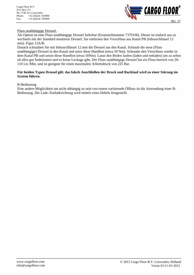
2012 Cargo Floor B.V. Coevorden, Holland
Versie 01/11-01-2012 www.cargofloor.com [email protected]
Cargo Floor B.V. P.O. Box 271 NL-7740 AG Coevorden Phone: +31-(0)524- 593900 Fax: +31-(0)524- 593999
Blz. 37 Fluss unabhängige Drossel. Als Option ist eine Fluss unabhängige Drossel lieferbar (Ersatzteilnummer 7370106). Dieser ist einfach aus zu wechseln mit der Standard montierte Drossel. Sie entfernen den Verschluss aus Kanal PB (Inbusschlüssel 12 mm). Figur 12A/B. Danach schrauben Sie mit Inbusschlüssel 12 mm die Drossel aus den Kanal. Schraub die neue (Fluss unabhängige) Drossel in den Kanal und setze diese Handfest (etwa 50 Nm). Schraube den Verschluss wieder in dem Kanal PB und setzte diese Handfest (etwa 50Nm). Lasse den Boden laufen (laden und entladen) um zu sehen ob alles gut funktioniert und es keine Leckage gibt. Der Fluss unabhängige Drossel hat ein Fluss bereich von 20-110 Ltr./Min. und ist geeignet für einen maximalen Arbeitsdruck von 225 Bar. Für beiden Typen Drossel gilt: das falsch Anschließen der Druck und Rucklauf wird zu einer Störung im System führen. B-Bedienung Eine andere Möglichkeit um nicht abhängig zu sein von einem variierende Ölfluss ist die Anwendung einer B-Bedienung. Die Lade-/Entladerichtung wird mittels eines Hebels festgestellt.
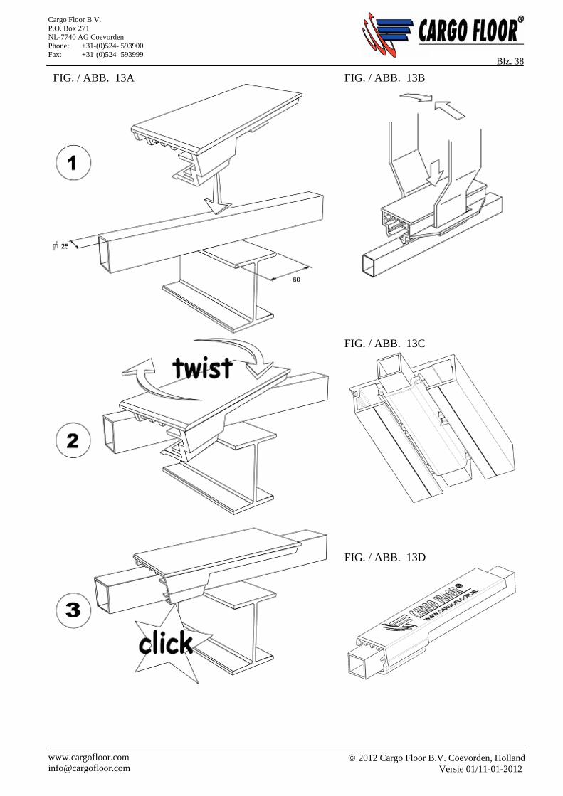
2012 Cargo Floor B.V. Coevorden, Holland
Versie 01/11-01-2012 www.cargofloor.com [email protected]
Cargo Floor B.V. P.O. Box 271 NL-7740 AG Coevorden Phone: +31-(0)524- 593900 Fax: +31-(0)524- 593999
Blz. 38
FIG. / ABB. 13A
FIG. / ABB. 13B
FIG. / ABB. 13C
FIG. / ABB. 13D
2012 Cargo Floor B.V. Coevorden, Holland
Versie 01/11-01-2012 www.cargofloor.com [email protected]
Cargo Floor B.V. P.O. Box 271 NL-7740 AG Coevorden Phone: +31-(0)524- 593900 Fax: +31-(0)524- 593999
Blz. 39
NL MONTAGE VAN KUNSTSTOF GELEIDERS “CARGO TWISTER”
Nadat de vierkante kokers (25x25 mm) gespoten zijn (let hierbij op dat de vierkante kokers niet te dik in de verf gespoten zijn en er zeker geen druppels aan zitten) kunnen de kunststof geleiders gemonteerd worden. Met de unieke gepatenteerde “CARGO TWISTER” kan dit eenvoudig, zonder gebruikmaking van gereedschappen, met één hand gebeuren. Men plaatst de “CARGO TWISTER” diagonaal over de vierkante koker en draait (twist) de geleider een kwartslag zodat de zgn. voetjes van de kunststof geleider onder de vierkante koker komen te zitten totdat men klik hoort. (Figuur 13A) Kick Twister Optioneel is de zgn. Kick Twister (figuur 13D) leverbaar. Met behulp van deze geleider is het mogelijk de aluminium vloerprofielen van bovenaf over de geleiders te monteren. Bij gebruik van deze Kick Twister is het noodzakelijk het Anti Lifting Block toe te passen. (Figuur 13C). Montage “oude” type kunststof geleider Daarvoor neemt men twee staalstrippen van 60 x 4 L=±300, zie figuur 13B, waarmee men vervolgens de kunststof geleiders gemakkelijk uit elkaar buigt en over de vierkante koker (25x25 mm) plaatst. Controleer of de kunststof geleiders goed bevestigd zijn. (Figuur 13B.) Anti Lifting Block Bij montage van vierkante kokers heeft men de mogelijkheid om een Anti Lifting Block tegen het omhoog komen van de aluminium profielen te monteren. Dit dient aan de los- / laadzijde van het voertuig, voorafgaand aan de montage van de aluminium vloerprofielen te worden gemonteerd. (Zie figuur 13C.) Advies: De overgebleven kunststof geleiders dienen op de laatst twee meter van de vierkante kokers tussen de dwarstraversen, te worden gemonteerd / opgemaakt.
GB MOUNTING THE PLASTIC GUIDES “CARGO TWISTER”
The plastic guides may be mounted after the square tubes (25x25 mm) have been sprayed (making sure that the paint layer is not too thick and that there are no paint drops). This can be easily done with one hand, without any tools, on the unique patented “CARGO TWISTER”. The “CARGO TWISTER” is placed diagonally over the square tube and the guide is rotated (twisted) through a quarter turn so that the so-called feet of the plastic guide move under the square tube and a click is heard. (Figure 13A.) Kick Twister As an option the so called Kick Twister (figure 13D) can be supplied. With the help of this guide it is possible to mount the aluminium floor profiles from above over the guides. When using these Kick Twisters it is necessary to also use the Anti Lifting Block. (Figure 13C.) Mounting “old” type plastic guide For this two steel strips of 60 x 4 L 300 are used, see figure 13B. These can be used to spread the plastic guide and hence to slide it over the square tube (25x25 mm). Check that the plastic guides are properly secured. (Figurs 13B) Anti Lifting Block It is possible (but not necessary) to mount a Anti Lifting Block profile while mounting the square tubes. This anti lifting block keeps the aluminium profiles in place. This should be done on the loading / unloading side of the vehicle, before the aluminium floor profiles have been mounted. Recommendation: The remaining plastic guides need to be mounted at the last two meters over the square tubes between the cross member.
2012 Cargo Floor B.V. Coevorden, Holland
Versie 01/11-01-2012 www.cargofloor.com [email protected]
Cargo Floor B.V. P.O. Box 271 NL-7740 AG Coevorden Phone: +31-(0)524- 593900 Fax: +31-(0)524- 593999
Blz. 40
D MONTAGE DER KUNSTSTOFF-FÜHRUNGEN "CARGO TWISTER" Nachdem die Vierkantrohre (25 x 25 mm) gespritzt (lackiert) wurden (hierbei ist zu beachten, dass die Vierkantrohre keinen zu starken Farbauftrag aufweisen und auf keinen Fall noch mögliche Resttropfen vorhanden sind), können die Kunststoff-Führungen montiert werden. Mit dem speziellen und patentierten "CARGO TWISTER" lässt sich dies auf einfache Weise, ohne den Einsatz von Werkzeugen, mit einer Hand durchführen. Man positioniert den "CARGO TWISTER" diagonal über dem Vierkantstab und dreht (daher: twist) die Führung um eine Vierteldrehung, so dass die sogenannten Stützen (die "Füße") der Kunststoff-Führung sich über dem Vierkantstab befinden, bis man ein "Klick" hört. (Abb. 13A.) Kick Twister Als Option ist ein so genannte Kick Twister (Abb. 13D) lieferbar. Mit Hilf dieser Führung ist es möglich die aluminium Bodenprofilen von oben über der Führung zu montieren. Bei Benutzung dieser Kick Twister ist es notwendig die Anti Lifiting Blocks zu benutzen. (Abb. 13C.) Montage des "alten" Typs von Kunststoff-Führungen Dazu werden zwei Stahlstreifen mit den Maßen 60 x 4 L = ±300 (siehe Abb. 13B) verwendet, mit denen man anschließend die Kunststoff-Führungen problemlos auseinander biegt und über dem Vierkantstab (25 x 25 mm) anbringt. Prüfen Sie, ob die Kunststoff-Führungen gut befestigt sind. (Abb. 13B.) Anti Lifting Block Bei der Montage der Vierkantrohre besteht die Möglichkeit (das ist kein "Muss"), ein Anti Lifting Block gegen das Hochkommen der Aluprofile zu montieren. Dies muss an der Lade- und Entladeseite des Fahrzeugs, vor der Montage der Aluminium-Bodenprofile geschehen. Hinweis: Die übrig gebliebenen Kunststoff-Führungen müssen auf die letzten zwei Meter über den Vierkantrohren zwischen den Querträgern montiert bzw. aufgebracht werden.
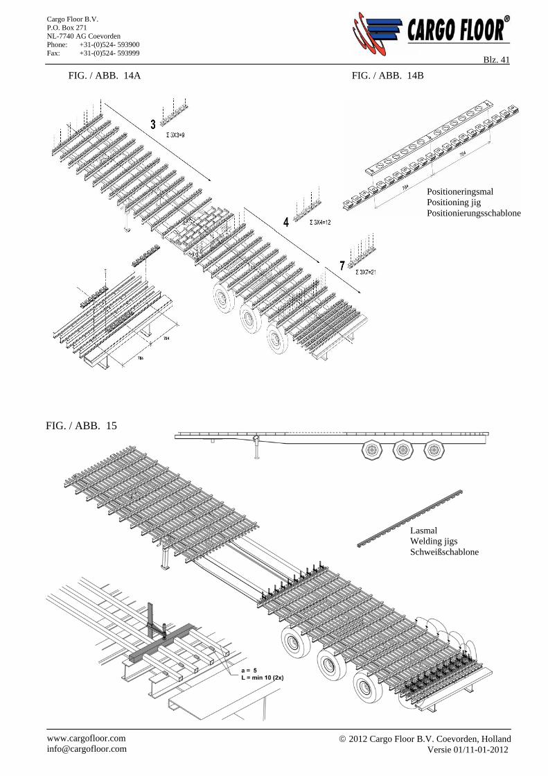
2012 Cargo Floor B.V. Coevorden, Holland
Versie 01/11-01-2012 www.cargofloor.com [email protected]
Cargo Floor B.V. P.O. Box 271 NL-7740 AG Coevorden Phone: +31-(0)524- 593900 Fax: +31-(0)524- 593999
Blz. 41
FIG. / ABB. 15
FIG. / ABB. 14A FIG. / ABB. 14B
Lasmal Welding jigs Schweißschablone
Positioneringsmal Positioning jig Positionierungsschablone
2012 Cargo Floor B.V. Coevorden, Holland
Versie 01/11-01-2012 www.cargofloor.com [email protected]
Cargo Floor B.V. P.O. Box 271 NL-7740 AG Coevorden Phone: +31-(0)524- 593900 Fax: +31-(0)524- 593999
Blz. 42 NL MONTAGE VAN DE SPECIALE KUNSTSTOF GELEIDINGSKAMMEN
Bij toepassing van de zgn. kunststof kamgeleiding dient men vooraf te controleren of de hoogte van de te gebruiken kamgeleiding overeenstemt met de hoogte van het aandrijfsysteem (zie bladzijde 18, figuur 6). De kamgeleidingen worden normaliter per drie stuks naast elkaar op een dwarstraverse gemonteerd. Hierbij dient het hart van het middelste blok van de kunststof kamgeleiding in de centerlijn van het chassis te worden gemonteerd. Op de kunststof kamgeleiding zijn hartlijnen aangegeven. Bij het monteren van de twee buitenste kamgeleidingen moet er opnieuw vanuit de centerlijn gemeten worden naar het hart van het middelste blok van de kunststof kamgeleiding, zie figuur 14B. Er zijn situaties waarbij het zgn. “zadelprincipe” van de kunststof kamgeleiding niet toegepast kan worden, hiervoor dient / kan men de oranje kunststof kamgeleiding te kiezen. LET OP: dit is alleen toepasbaar bij kunststof kamgeleiding met een hoogte van 35 mm. Door het zgn. “zadelprincipe” van de kunststof kamgeleidingen is het niet noodzakelijk elk bevestigingsgat in deze kunststof kamgeleiding te gebruiken. (Zie figuur 14A.) Aantal bevestigingspunten: Vanaf de voorzijde van de oplegger tot aan het aandrijfsysteem dient bij elke kunststof geleidingskam de
buitenste gaten en het middelste gat te worden gebruikt (3 per geleidingskam, 9 per dwarstraverse). Vanaf het aandrijfsysteem tot circa 2000 mm voor de laad- / loszijde van het frame dient per kamgeleiding elk
tweede gat te worden gebruikt, beginnende bij het eerste gat (4 per geleidingskam, 12 per dwarstraverse). De laatste twee meter van het frame dienen alle aanwezige gaten te worden gebruikt. Bij gebruik van geleidingskammen zonder het zgn. “zadelprincipe” (oranje kamgeleiding) dienen alle
aanwezige gaten te worden gebruikt. Het is hierbij raadzaam een dwarsligger met een bovenflensbreedte van maximaal 60 mm te gebruiken, deze mag niet smaller dan 50 mm zijn. Er kunnen tevens afwijkende maten worden toegepast door gebruikmaking van speciaal hiervoor bestemde kunststof kamgeleidingen. Nb. bij het gebruik van deze kunststof kamgeleiding adviseren wij u nadrukkelijk om een stabiele dwarstraverse toe te passen en ervoor te zorgen dat het onderframe sterk genoeg is. Voor de uitlijning adviseren wij u onze positioneringsmal, artikelnummer 9111201, te gebruiken. Zie figuur 14B.
GB MOUNTING THE SPECIAL PLASTIC CAM GUIDES
A check needs to be made, that the heights of the cam guide and the drive system are in agreement before mounting the so-called plastic cam guides (see page 18, fig 6). The cam guides are normally mounted adjacently in three’s on a crossbeam. In this case the centre of the middle block of the middle guide needs to be mounted along the centre line of the chassis. The centre lines are shown on the plastic cam guides. When mounting the two outer cam guides, one needs again to measure from the chassis centre line to the centre of the middle block in the plastic cam guide, see figure 14B. There are situations where the so-called “saddle principle” of the plastic cam guides can not be used, in such cases the orange plastic cam guides need to be chosen. ATTENTION: this can only be done with 35 mm high plastic cam guides. Thanks to the so-called “saddle principle” of the plastic cam guides, it is not necessary to use every mounting hole in the plastic cam guide. (See figure 14A.) Number of mounting points: The outer and centre hole of each plastic cam guide from the front of the trailer to the drive system need to be
used (3 per cam guide, 9 per crossbeam). Every second hole, starting at the first hole, of each cam guide from the drive system to about 2000 mm away
from the loading / unloading side of the frame needs to be used (4 per cam guide, 12 per crossbeam). All of the holes over the last two metres of the frame need to be used. When using cam guides that don’t use the so-called “saddle principle” one needs to use all mounting holes.
2012 Cargo Floor B.V. Coevorden, Holland
Versie 01/11-01-2012 www.cargofloor.com [email protected]
Cargo Floor B.V. P.O. Box 271 NL-7740 AG Coevorden Phone: +31-(0)524- 593900 Fax: +31-(0)524- 593999
Blz. 43 Use of a crossbeam with a top flange width of maximum 60 mm is recommended, it must be wider than 50 mm. Other widths can be used, but only if specially designed plastic cam guides are utilised. N.B. We strongly advise you, that if you use these plastic cam guides to ensure that a stable crossbeam is used and that the support frame is strong enough. We advise to use our positioning jig, article code 9111201 for the positioning. See figure 14B.
D MONTAGE DER SPEZIAL-KUNSTSTOFF-GLEITKÄMME Beim Einsatz der sogenannten Kunststoff-Gleitkämme muss vorher überprüft werden, ob die Höhe der zu verwendenden Kammführung mit der Höhe des Antriebssystems übereinstimmt (siehe Seite 18, fig. 6). Die Kammführungen werden in der Regel zu je drei Stück nebeneinander auf einem Querträger montiert. Hierbei muss das Herzstück des mittleren Blocks der Kunststoff-Kammführung entlang der Mittelachse des Chassis montiert werden. Auf der Kunststoff-Kammführung sind Achslinien zur Ausrichtung angegeben. Bei der Montage der zwei äußeren Kammführungen muss erneut ab der Mittelachse zum Herzstück des mittleren Blocks der Kunststoff-Kammführung ausgemessen werden (siehe Abb. 14B). Es gibt Fälle, bei denen das "Sattelprinzip" der Kunststoff-Kammführung nicht eingesetzt werden kann, dann muss bzw. kann die orangefarbene Kunststoff-Kammführung verwendet werden. ACHTUNG: Dies gilt nur für eine Kunststoff-Kammführung mit einer Höhe von 35 mm. Durch das sogenannte "Sattelprinzip" der Kunststoff-Kammführungen ist es nicht erforderlich, jedes Befestigungsloch in dieser Kammführung zu verwenden. (sehe Abb. 14A.) Zahl der Befestigungspunkte: Von der Vorderseite des Auflegers bis zum Antriebssystem müssen bei jedem Kunststoff-Gleitkamm die
äußeren Löcher und das mittlere Loch benutzt werden (3 je Gleitkamm, 9 je Querträger). Vom Antriebssystem bis ca. 2000 mm vor der Lade- und Entladeseite des Rahmens muss bei jeder
Kammführung jedes zweite Loch benutzt werden, jeweils beginnend mit dem ersten Loch (4 je Gleitkamm, 12 je Querträger).
Bei den letzten zwei Metern des Querträgers müssen alle vorhandenen Löcher benutzt werden. Bei Verwendung von Gleitkämmen ohne das sogenannte "Sattelprinzip" (also mit orangefarbener
Kammführung) müssen alle vorhandenen Löcher benutzt werden. Hier ist es ratsam, einen Querträger mit einer Kopfflanschbreite von maximal 60 mm zu verwenden, auf keinen Fall aber weniger als 50 mm. Abweichende Maße können durch die Verwendung von hierfür bestimmten, speziellen Kunststoff-Kammführungen benutzt werden. Hinweis: Beim Einsatz dieser Kunststoff-Kammführung empfehlen wir ausdrücklich, einen stabilen Querträger zu verwenden und dafür zu sorgen, dass der Unterrahmen stark genug ausgelegt ist. Wir advisieren fürs ausrichten unsere Positionierungsschablone, Ersatzteilnummer 9111201, zu benutzen. Sehe Abb. 14B
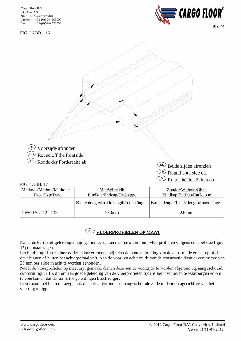
2012 Cargo Floor B.V. Coevorden, Holland
Versie 01/11-01-2012 www.cargofloor.com [email protected]
Cargo Floor B.V. P.O. Box 271 NL-7740 AG Coevorden Phone: +31-(0)524- 593900 Fax: +31-(0)524- 593999
Blz. 44 FIG. / ABB. 16
FIG. / ABB. 17 Methode/Method/Methode Met/With/Mit Zonder/Without/Ohne
Type/Typ/Type Eindkap/Endcap/Endkappe Eindkap/Endcap/Endkappe
CF500 SL-2 21-112
Binnenlengte/Inside length/Innenlänge
280mm
Binnenlengte/Inside length/Innenlänge
240mm
NL VLOERPROFIELEN OP MAAT Nadat de kunststof geleidingen zijn gemonteerd, kan men de aluminium vloerprofielen volgens de tabel (zie figuur 17) op maat zagen. Let hierbij op dat de vloerprofielen korter moeten zijn dan de binnenafmeting van de constructie en let op of de deur binnen of buiten het achterportaal valt. Aan de voor- en achterzijde van de constructie dient er een ruimte van 20 mm per zijde in acht te worden gehouden. Nadat de vloerprofielen op maat zijn gemaakt dienen deze aan de voorzijde te worden afgerond cq. aangeschuind, conform figuur 16, dit om een goede geleiding van de vloerprofielen tijdens het inschuiven te waarborgen en om te voorkomen dat de kunststof geleidingen beschadigen. In verband met het montagegemak dient de afgeronde cq. aangeschuinde zijde in de montagerichting van het voertuig te liggen.
NL Beide zijden afronden GB Round both side off D Ronde beiden Seiten ab
NL Voorzijde afronden GB Round off the frontside D Ronde der Forderseite ab
2012 Cargo Floor B.V. Coevorden, Holland
Versie 01/11-01-2012 www.cargofloor.com [email protected]
Cargo Floor B.V. P.O. Box 271 NL-7740 AG Coevorden Phone: +31-(0)524- 593900 Fax: +31-(0)524- 593999
Blz. 45
GB CUTTING THE FLOOR PROFILES TO SIZE The aluminium floor profiles can be cut to size according to the table (see figure 17) after the plastic guides have been mounted. Pay attention to the fact that the floor profiles must be shorter than the inner measurement of the construction, and take into account whether the door is inside or outside the tailgate. A space of 20 mm should be adhered to at the front and rear of the construction. After cutting the floor profiles to length they need to be rounded-off (bevelled) at the front according to figure 16, so as to ensure a smooth guiding of the floor profile while sliding in, and to prevent damage to the plastic guides. To aid mounting, the rounded-off (bevelled) side needs to lie in the mounting direction of the vehicle.
D BODENPROFILE AUF MASS BRINGEN Nachdem die Kunststoff-Führungen montiert sind, kann man die Aluminium-Bodenprofile gemäß der Tabelle (siehe Abb. 17) auf Maß sägen. Achten Sie hierbei darauf, dass die Bodenprofile kürzer sein müssen als die Innenmaße der Konstruktion, und berücksichtigen Sie, ob sich die Tür innerhalb oder außerhalb der hinteren Öffnung (hintere Tür) befindet. An der vorderen und an der hinteren Seite der Konstruktion muss ein Abstand von 20 mm an jeder Seite kalkuliert werden. Nachdem die Bodenprofile auf Maß gebracht sind, müssen diese an der Vorderseite gerundet bzw. angeschrägt werden (siehe Abb. 16). Dies ist erforderlich, um einen guten Gleiteffekt der Bodenprofile beim Einschieben zu gewährleisten und um zu vermeiden, dass die Kunststoff-Führungen beschädigt werden. Zur Erleichterung der Montage muss die abgerundete bzw. angeschrägte Seite in die Montagerichtung des Fahrzeugs weisen.
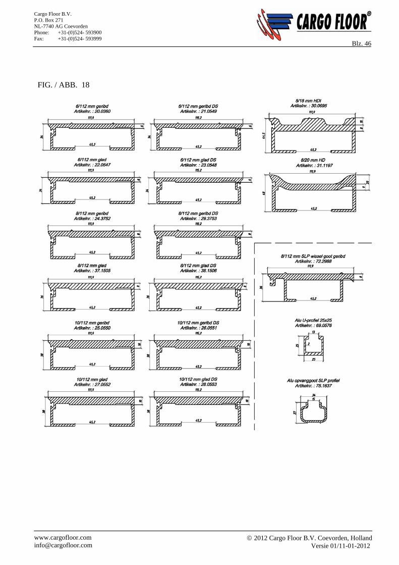
2012 Cargo Floor B.V. Coevorden, Holland
Versie 01/11-01-2012 www.cargofloor.com [email protected]
Cargo Floor B.V. P.O. Box 271 NL-7740 AG Coevorden Phone: +31-(0)524- 593900 Fax: +31-(0)524- 593999
Blz. 46
FIG. / ABB. 18
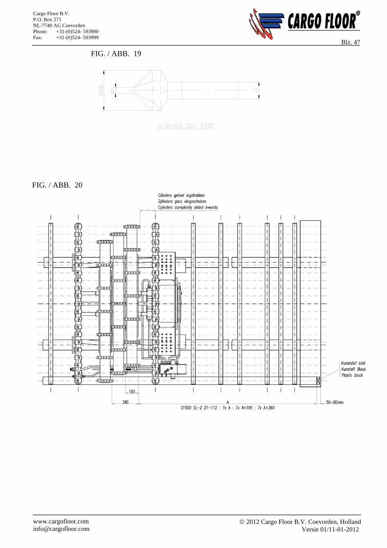
2012 Cargo Floor B.V. Coevorden, Holland
Versie 01/11-01-2012 www.cargofloor.com [email protected]
Cargo Floor B.V. P.O. Box 271 NL-7740 AG Coevorden Phone: +31-(0)524- 593900 Fax: +31-(0)524- 593999
Blz. 47
FIG. / ABB. 19
FIG. / ABB. 20
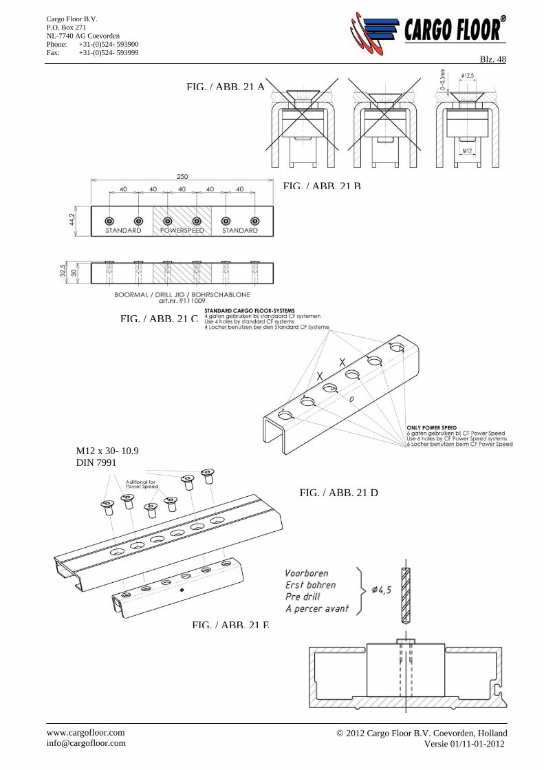
2012 Cargo Floor B.V. Coevorden, Holland
Versie 01/11-01-2012 www.cargofloor.com [email protected]
Cargo Floor B.V. P.O. Box 271 NL-7740 AG Coevorden Phone: +31-(0)524- 593900 Fax: +31-(0)524- 593999
Blz. 48
FIG. / ABB. 21 C
FIG. / ABB. 21 A
FIG. / ABB. 21 B
FIG. / ABB. 21 E
FIG. / ABB. 21 D
M12 x 30- 10.9 DIN 7991
2012 Cargo Floor B.V. Coevorden, Holland
Versie 01/11-01-2012 www.cargofloor.com [email protected]
Cargo Floor B.V. P.O. Box 271 NL-7740 AG Coevorden Phone: +31-(0)524- 593900 Fax: +31-(0)524- 593999
Blz. 49 NL HET BOREN VAN DE GATEN IN DE VLOERPROFIELEN
Het boren van de gaten in de vloerdelen dient te gebeuren voordat deze worden geplaatst. Men dient er op te letten dat door de verschillende afstanden van de bewegende framevoeten in het aandrijfsyteem de gaten versprongen moeten worden geboord (zie figuur 20, bladzijde 38). Het opmeten van de gaten dient als volgt te gebeuren: Controleer of alle 3 de cilinders geheel ingetrokken zijn. U controleert dit als volgt, de uiteinden van de
zuigerstangen mogen niet verder dan 5-10 mm uit de kunststof stanggeleiding steken; Meet volgens figuur 20 de maat van de binnenzijde achterdeur tot het eerste gat in de vinger die gemonteerd zit
op de bewegende framevoet welke het dichtst bij de cilinders zit. Bij gebruik van een Cargo Floor schuine eindkap trekt u 50 tot 60 mm (is 40 mm voor de eindkap + 10-20 mm extra ruimte) van deze maat af. Bij gebruik van een andere eindafdichting voor het vloerprofiel trekt u, de maat van het uitstekende deel van deze eindafdichting + 10 tot 20 mm af.
Voordat u gaat boren dienen alle vloerprofielen met de afdichtingsgroef in dezelfde richting te liggen. Let hierbij speciaal op dat het sluitprofiel (figuur 18, bladzijde 37) met een groef aan twee zijden geboord wordt op de afstand welke overeenkomt met het gatenpatroon van de eerste of laatste bewegende framevoet.
Boor vervolgens conform figuur 21 het benodigd aantal vloerprofielen per bewegende framevoet (bij een standaard 21-planks systeem zijn dit 7 vloerprofielen). Gebruik hiervoor de Cargo Floor boormal, artikelnummer 9111009.
Met de boormal boort u aan de binnenzijde van het vloerprofiel 4 gaten (voor de Power Speed 6 gaten, zie inbouwhandleiding Power Speed) van Ø 4,5 mm voor, waarbij de meegeextrudeerde referentielijn het midden van het boorgat aangeeft. Daarna boort u vanaf dezelfde richting de gaten op tot rond Ø 12,5 mm.
Vervolgens dient men de gaten vanaf de bovenzijde te verzinken. Gebruik hiervoor een goede verzinkboor volgens specificatie G136 HSS DIN 335 C, code G13628.0 (zie figuur 19, bladzijde 38). Let goed op dat het gat tot op de juiste diepte verzonken wordt, de kop van de bout mag nooit boven en onder het vloerprofiel uitsteken. Zie figuur 21.
GB DRILLING THE HOLES IN THE FLOOR PROFILES
The holes in the floor parts need to be drilled before these are placed. One needs to pay attention to the fact that the holes must be drilled staggered due to the differing distances of the moving frame feet in the drive system (see figure 20, page 38). The positions of the holes need to be measured as follows: Check that all 3 cylinders are completely retracted. You check this by seeing that the ends of the piston rods
protrude no more than 10 mm out of the plastic rod guides; Measure according to figure 20 the length from the inside of the rear door to the first hole in the finger that is
mounted on the moving frame foot that is closest to the cylinders. If a bevelled Cargo Floor end cap is used you need to subtract 50 to 60 mm (40 mm for the end cap + 10-20 mm extra space) from this measurement. If another form of end cap is used for the floor profile then you need to subtract the protruding length of the end cap plus 10 to 20 mm.
Place all of the floor profiles with the sealing grooves in the same direction before you start drilling. Pay special attention to ensuring that the end profiles (with a groove, figure 18 page 37) are drilled on both sides at a distance that agrees with the pattern of holes for the first or last moving frame foot.
Then drill according to figure 21the necessary number of floor profiles per moving frame foot (this is 7 floor profiles for a standard 21-plank system), using the Cargo Floor drill jig, part number 9111009.
Drill 4 holes (for the Power Speed 6 holes, see assembly instructions Power Speed) of Ø 4.5 mm with the aid of the drill jig on the inside of the floor profile ensuring the centre of the holes line up with the extruded reference line. Then bore out the holes, from the same direction, to about Ø 12.5 mm
Next the holes need to be countersunk from the top side using a good countersink bit according to the specification G136 HSS DIN 335 C, code 13628.0 (figure 19, page 38) Make sure that the hole is countersunk to the right depth; the bolt head must not stick out above or under the floor profile. See figure 21.
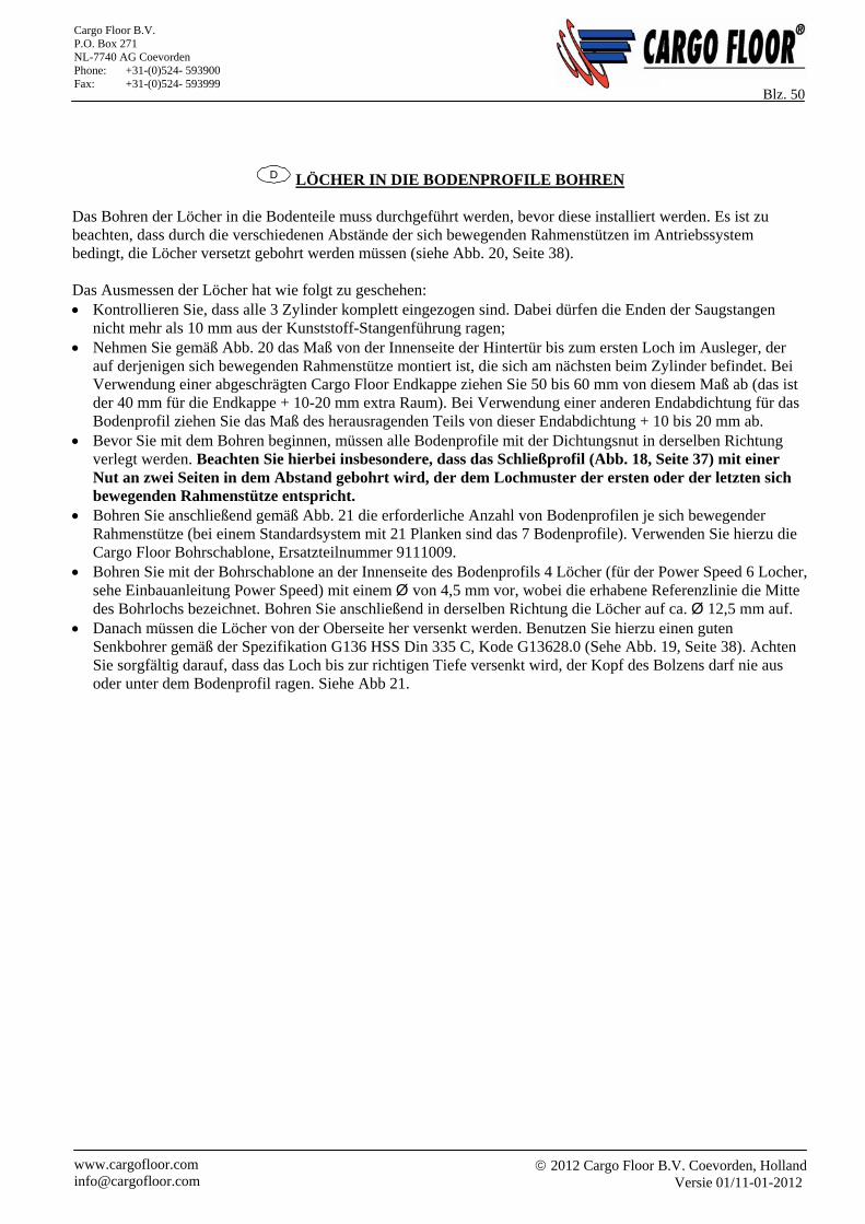
2012 Cargo Floor B.V. Coevorden, Holland
Versie 01/11-01-2012 www.cargofloor.com [email protected]
Cargo Floor B.V. P.O. Box 271 NL-7740 AG Coevorden Phone: +31-(0)524- 593900 Fax: +31-(0)524- 593999
Blz. 50
D LÖCHER IN DIE BODENPROFILE BOHREN
Das Bohren der Löcher in die Bodenteile muss durchgeführt werden, bevor diese installiert werden. Es ist zu beachten, dass durch die verschiedenen Abstände der sich bewegenden Rahmenstützen im Antriebssystem bedingt, die Löcher versetzt gebohrt werden müssen (siehe Abb. 20, Seite 38). Das Ausmessen der Löcher hat wie folgt zu geschehen: Kontrollieren Sie, dass alle 3 Zylinder komplett eingezogen sind. Dabei dürfen die Enden der Saugstangen
nicht mehr als 10 mm aus der Kunststoff-Stangenführung ragen; Nehmen Sie gemäß Abb. 20 das Maß von der Innenseite der Hintertür bis zum ersten Loch im Ausleger, der
auf derjenigen sich bewegenden Rahmenstütze montiert ist, die sich am nächsten beim Zylinder befindet. Bei Verwendung einer abgeschrägten Cargo Floor Endkappe ziehen Sie 50 bis 60 mm von diesem Maß ab (das ist der 40 mm für die Endkappe + 10-20 mm extra Raum). Bei Verwendung einer anderen Endabdichtung für das Bodenprofil ziehen Sie das Maß des herausragenden Teils von dieser Endabdichtung + 10 bis 20 mm ab.
Bevor Sie mit dem Bohren beginnen, müssen alle Bodenprofile mit der Dichtungsnut in derselben Richtung verlegt werden. Beachten Sie hierbei insbesondere, dass das Schließprofil (Abb. 18, Seite 37) mit einer Nut an zwei Seiten in dem Abstand gebohrt wird, der dem Lochmuster der ersten oder der letzten sich bewegenden Rahmenstütze entspricht.
Bohren Sie anschließend gemäß Abb. 21 die erforderliche Anzahl von Bodenprofilen je sich bewegender Rahmenstütze (bei einem Standardsystem mit 21 Planken sind das 7 Bodenprofile). Verwenden Sie hierzu die Cargo Floor Bohrschablone, Ersatzteilnummer 9111009.
Bohren Sie mit der Bohrschablone an der Innenseite des Bodenprofils 4 Löcher (für der Power Speed 6 Locher, sehe Einbauanleitung Power Speed) mit einem Ø von 4,5 mm vor, wobei die erhabene Referenzlinie die Mitte des Bohrlochs bezeichnet. Bohren Sie anschließend in derselben Richtung die Löcher auf ca. Ø 12,5 mm auf.
Danach müssen die Löcher von der Oberseite her versenkt werden. Benutzen Sie hierzu einen guten Senkbohrer gemäß der Spezifikation G136 HSS Din 335 C, Kode G13628.0 (Sehe Abb. 19, Seite 38). Achten Sie sorgfältig darauf, dass das Loch bis zur richtigen Tiefe versenkt wird, der Kopf des Bolzens darf nie aus oder unter dem Bodenprofil ragen. Siehe Abb 21.
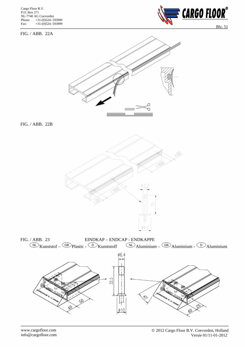
2012 Cargo Floor B.V. Coevorden, Holland
Versie 01/11-01-2012 www.cargofloor.com [email protected]
Cargo Floor B.V. P.O. Box 271 NL-7740 AG Coevorden Phone: +31-(0)524- 593900 Fax: +31-(0)524- 593999
Blz. 51 FIG. / ABB. 22A
FIG. / ABB. 22B
FIG. / ABB. 23 EINDKAP – ENDCAP - ENDKAPPE
NL Kunststof – GB Plastic - D Kunststoff NL Aluminium – GB Aluminium - D Aluminium
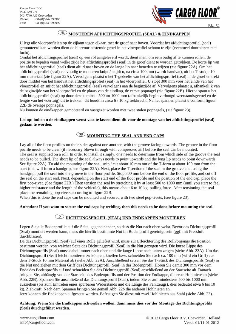
2012 Cargo Floor B.V. Coevorden, Holland
Versie 01/11-01-2012 www.cargofloor.com [email protected]
Cargo Floor B.V. P.O. Box 271 NL-7740 AG Coevorden Phone: +31-(0)524- 593900 Fax: +31-(0)524- 593999
Blz. 52 NL MONTEREN AFDICHTINGSPROFIEL (SEAL) & EINDKAPPEN
U legt alle vloerprofielen op de zijkant tegen elkaar, met de groef naar boven. Voordat het afdichtingsprofiel (seal) gemonteerd kan worden dient de hiervoor bestemde groef in het vloerprofiel schoon te zijn (eventueel doorblazen met lucht). Omdat het afdichtingsprofiel (seal) op een rol aangeleverd wordt, dient men, om eenvoudig af te kunnen rollen, de positie te bepalen vanaf welke zijde het afdichtingsprofiel (seal) in de groef dient te worden getrokken. De korte lip van het afdichtingsprofiel (seal) dient altijd naar boven en de lange lip naar beneden te wijzen (zie figuur 22A). Om het afdichtingsprofiel (seal) eenvoudig te monteren knipt / snijdt u, na circa 100 mm (wordt handvat), uit het T-stukje 10 mm materiaal (zie figuur 22A). Vervolgens plaatst u het T-gedeelte van het afdichtingsprofiel (seal) in de groef en trekt door middel van het handvat het afdichtingsprofiel (seal) in het vloerprofiel. U stopt 300 mm voor het einde van het vloerprofiel en snijdt het afdichtingsprofiel (seal) vervolgens aan de beginzijde af. Vervolgens plaatst u, afhankelijk van de beginzijde van het vloerprofiel en de plaats van de eindkap, de eerste popnagel (zie figuur 22B). Hierna spant u het afdichtingsprofiel (seal) op door deze teminste 500 tot 1000 mm (afhankelijk begin verhoogd weerstandsgevoel en de lengte van het voertuig) uit te trekken, dit houdt in circa 6 / 10 kg trekkracht. Na het spannen plaatst u conform figuur 22B de overige popnagels. Nu kunnen de eindkappen gemonteerd en vastgezet worden met twee stalen popnagels, (zie figuur 23). Let op: indien u de eindkappen wenst vast te lassen dient dit voor de montage van het afdichtingsprofiel (seal) gedaan te worden.
GB MOUNTING THE SEAL AND END CAPS
Lay all of the floor profiles on their sides against one another, with the groove facing upwards. The groove in the floor profile needs to be clean (if necessary blown through with compressed air) before the seal can be mounted. The seal is supplied on a roll. In order to install it simply, one needs to determine from which side of the groove the seal needs to be pulled. The short lip of the seal always needs to point upwards and the long lip needs to point downwards See figure 22A). To aid the mounting of the seal, snip / cut about 10 mm out of the T-form at about 100 mm from the start (this will form a handgrip, see figure 22A). Next, place the T section of the seal in the groove and, using the handgrip, pull the seal into the groove in the floor profile. Stop 300 mm before the end of the floor profile, and cut off the seal on the start end. Next, depending on the start end of the floor profile and the position of the end cap, place the first pop-rivet. (See figure 22B.) Then tension the seal by stretching it by at least 500 to 1000 mm (until you start to feel higher resistance and the length of the vehicule), this means about 6 to 10 kg. pulling force. After tensioning the seal place the remaining pop-rivets according to figure 22B. When this is done the end caps can be mounted and secured with two steel pop-rivets, (see figure 23). Attention: If you want to secure the end caps by welding, then this needs to be done before mounting the seal.
D DICHTUNGSPROFIL (SEAL) UND ENDKAPPEN MONTIEREN
Legen Sie alle Bodenprofile auf die Seite, gegeneinander, so dass die Nut nach oben weist. Bevor das Dichtungsprofil (Seal) montiert werden kann, muss die hierfür bestimmte Nut im Bodenprofil gereinigt sein (ggf. mit Pressluft durchblasen). Da das Dichtungsprofil (Seal) auf einer Rolle geliefert wird, muss zur Erleichterung des Rollvorgangs die Position bestimmt werden, von welcher Seite das Dichtungsprofil (Seal) in die Nut gezogen wird. Die kurze Lippe des Dichtungsprofils (Seal) muss dabei immer nach oben und die lange Lippe nach unten zeigen (siehe Abb. 22A). Um das Dichtungsprofil (Seal) leicht montieren zu können, kneifen bzw. schneiden Sie nach ca. 100 mm (wird ein Griff) aus dem T-Stück 10 mm Material ab (siehe Abb. 22A). Anschließend setzen Sie das T-Stück des Dichtungsprofils (Seal) in die Nut und ziehen mit dem Griff das Dichtungsprofil (Seal) in das Bodenprofil. Hören Sie damit 300 mm vor dem Ende des Bodenprofils auf und schneiden Sie das Dichtungsprofil (Seal) anschließend an der Startseite ab. Danach bringen Sie, abhängig von der Startseite des Bodenprofils und der Position der Endkappe, die erste Hohlniete an (siehe Abb. 22B). Spannen Sie anschließend das Dichtungsprofil (Seal), indem Sie es auf mindestens 500 bis 1000 mm ausziehen (bis zum Eintreten eines spürbaren Widerstands und die Länge des Fahrzeugs), dies bedeutet etwa 6 bis 10 kg. Ziehkraft. Nach dem Spannen bringen Sie gemäß Abb. 22b die anderen Hohlnieten an. Jetzt können die Endkappen aufgesetzt werden. Befestigen Sie diese mit zwei Hohlnieten aus Stahl (siehe Abb. 23). Achtung: Wenn Sie die Endkappen schweißen wollen, dann muss dies vor der Montage des Dichtungsprofils (Seal) durchgeführt werden.
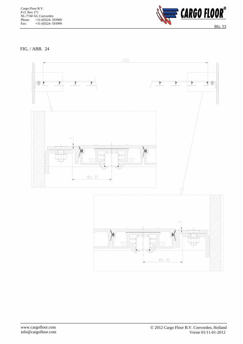
2012 Cargo Floor B.V. Coevorden, Holland
Versie 01/11-01-2012 www.cargofloor.com [email protected]
Cargo Floor B.V. P.O. Box 271 NL-7740 AG Coevorden Phone: +31-(0)524- 593900 Fax: +31-(0)524- 593999
Blz. 53 FIG. / ABB. 24
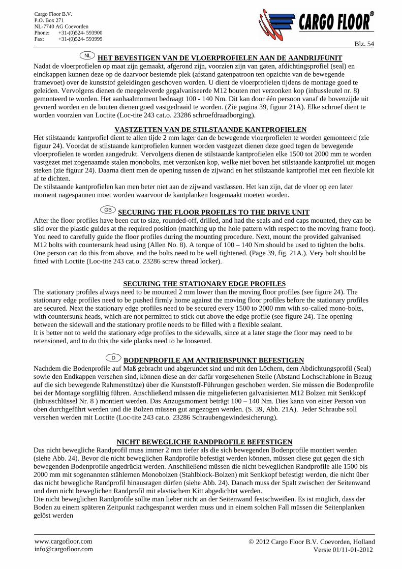
2012 Cargo Floor B.V. Coevorden, Holland
Versie 01/11-01-2012 www.cargofloor.com [email protected]
Cargo Floor B.V. P.O. Box 271 NL-7740 AG Coevorden Phone: +31-(0)524- 593900 Fax: +31-(0)524- 593999
Blz. 54 NL HET BEVESTIGEN VAN DE VLOERPROFIELEN AAN DE AANDRIJFUNIT
Nadat de vloerprofielen op maat zijn gemaakt, afgerond zijn, voorzien zijn van gaten, afdichtingsprofiel (seal) en eindkappen kunnen deze op de daarvoor bestemde plek (afstand gatenpatroon ten opzichte van de bewegende framevoet) over de kunststof geleidingen geschoven worden. U dient de vloerprofielen tijdens de montage goed te geleiden. Vervolgens dienen de meegeleverde gegalvaniseerde M12 bouten met verzonken kop (inbussleutel nr. 8) gemonteerd te worden. Het aanhaalmoment bedraagt 100 - 140 Nm. Dit kan door één persoon vanaf de bovenzijde uit gevoerd worden en de bouten dienen goed vastgedraaid te worden. (Zie pagina 39, figuur 21A). Elke schroef dient te worden voorzien van Loctite (Loc-tite 243 cat.o. 23286 schroefdraadborging).
VASTZETTEN VAN DE STILSTAANDE KANTPROFIELEN Het stilstaande kantprofiel dient te allen tijde 2 mm lager dan de bewegende vloerprofielen te worden gemonteerd (zie figuur 24). Voordat de stilstaande kantprofielen kunnen worden vastgezet dienen deze goed tegen de bewegende vloerprofielen te worden aangedrukt. Vervolgens dienen de stilstaande kantprofielen elke 1500 tot 2000 mm te worden vastgezet met zogenaamde stalen monobolts, met verzonken kop, welke niet boven het stilstaande kantprofiel uit mogen steken (zie figuur 24). Daarna dient men de opening tussen de zijwand en het stilstaande kantprofiel met een flexible kit af te dichten. De stilstaande kantprofielen kan men beter niet aan de zijwand vastlassen. Het kan zijn, dat de vloer op een later moment nagespannen moet worden waarvoor de kantplanken losgemaakt moeten worden.
GB SECURING THE FLOOR PROFILES TO THE DRIVE UNIT After the floor profiles have been cut to size, rounded-off, drilled, and had the seals and end caps mounted, they can be slid over the plastic guides at the required position (matching up the hole pattern with respect to the moving frame foot). You need to carefully guide the floor profiles during the mounting procedure. Next, mount the provided galvanised M12 bolts with countersunk head using (Allen No. 8). A torque of 100 – 140 Nm should be used to tighten the bolts. One person can do this from above, and the bolts need to be well tightened. (Page 39, fig. 21A.). Very bolt should be fitted with Loctite (Loc-tite 243 cat.o. 23286 screw thread locker).
SECURING THE STATIONARY EDGE PROFILES The stationary profiles always need to be mounted 2 mm lower than the moving floor profiles (see figure 24). The stationary edge profiles need to be pushed firmly home against the moving floor profiles before the stationary profiles are secured. Next the stationary edge profiles need to be secured every 1500 to 2000 mm with so-called mono-bolts, with countersunk heads, which are not permitted to stick out above the edge profile (see figure 24). The opening between the sidewall and the stationary profile needs to be filled with a flexible sealant. It is better not to weld the stationary edge profiles to the sidewalls, since at a later stage the floor may need to be retensioned, and to do this the side planks need to be loosened.
D BODENPROFILE AM ANTRIEBSPUNKT BEFESTIGEN
Nachdem die Bodenprofile auf Maß gebracht und abgerundet sind und mit den Löchern, dem Abdichtungsprofil (Seal) sowie den Endkappen versehen sind, können diese an der dafür vorgesehenen Stelle (Abstand Lochschablone in Bezug auf die sich bewegende Rahmenstütze) über die Kunststoff-Führungen geschoben werden. Sie müssen die Bodenprofile bei der Montage sorgfältig führen. Anschließend müssen die mitgelieferten galvanisierten M12 Bolzen mit Senkkopf (Inbusschlüssel Nr. 8 ) montiert werden. Das Anzugsmoment beträgt 100 – 140 Nm. Dies kann von einer Person von oben durchgeführt werden und die Bolzen müssen gut angezogen werden. (S. 39, Abb. 21A). Jeder Schraube soll versehen werden mit Loctite (Loc-tite 243 cat.o. 23286 Schraubengewindesicherung).
NICHT BEWEGLICHE RANDPROFILE BEFESTIGEN Das nicht bewegliche Randprofil muss immer 2 mm tiefer als die sich bewegenden Bodenprofile montiert werden (siehe Abb. 24). Bevor die nicht beweglichen Randprofile befestigt werden können, müssen diese gut gegen die sich bewegenden Bodenprofile angedrückt werden. Anschließend müssen die nicht beweglichen Randprofile alle 1500 bis 2000 mm mit sogenannten stählernen Monobolzen (Stahlblock-Bolzen) mit Senkkopf befestigt werden, die nicht über das nicht bewegliche Randprofil hinausragen dürfen (siehe Abb. 24). Danach muss der Spalt zwischen der Seitenwand und dem nicht beweglichen Randprofil mit elastischem Kitt abgedichtet werden. Die nicht beweglichen Randprofile sollte man lieber nicht an der Seitenwand festschweißen. Es ist möglich, dass der Boden zu einem späteren Zeitpunkt nachgespannt werden muss und in einem solchen Fall müssen die Seitenplanken gelöst werden
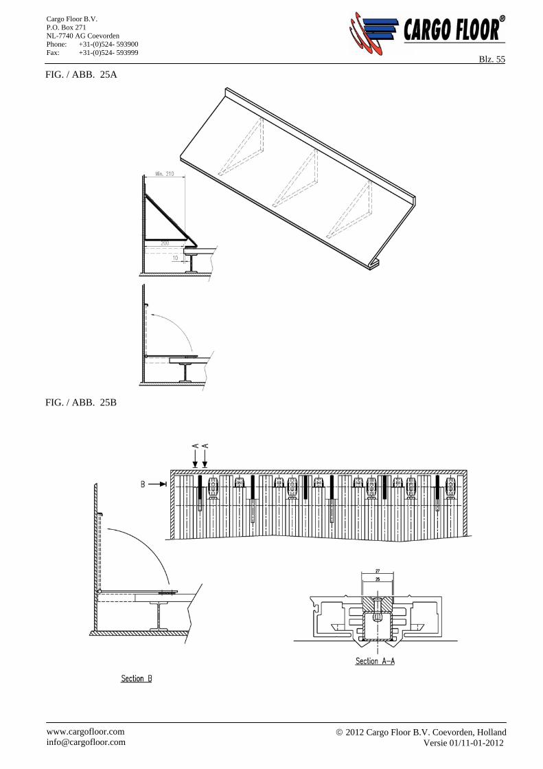
2012 Cargo Floor B.V. Coevorden, Holland
Versie 01/11-01-2012 www.cargofloor.com [email protected]
Cargo Floor B.V. P.O. Box 271 NL-7740 AG Coevorden Phone: +31-(0)524- 593900 Fax: +31-(0)524- 593999
Blz. 55 FIG. / ABB. 25A
FIG. / ABB. 25B
2012 Cargo Floor B.V. Coevorden, Holland
Versie 01/11-01-2012 www.cargofloor.com [email protected]
Cargo Floor B.V. P.O. Box 271 NL-7740 AG Coevorden Phone: +31-(0)524- 593900 Fax: +31-(0)524- 593999
Blz. 56 NL AFDICHTEN VAN DE VOOR- / ACHTERZIJDE VAN DE VLOER.
Voorzijde Om de opening ten gevolge van de arbeidsslag van het systeem af te kunnen dichten kan men een verstevigde vlakke plaat (lengte minimaal 250 mm, breedte afhanklijk van de binnenzijde van de bak) scharnierbaar monteren aan de voorwand van de bak. Om slijtage te voorkomen en een goede afdichting te waarborgen dient aan de onderzijde van het voorste gedeelte van de afdichtplaat de meegeleverde kunststof strip (2500x75x5 mm) te worden gemonteerd. Om een optimale afdichting te realiseren, dienen bij de vloerprofielen met ribbel, de ribbel over een lengte van circa 250 mm te worden glad geslepen. Let hierbij op dat het gebruikte bevestigingsmateriaal verzonken in de kunststof strip wordt gemonteerd zodat deze niet in contact komt met de vloer. Vervoert men veel pallets, of verliest men met bovenstaande constructie te veel ruimte, dan kan men kiezen voor de methode volgens figuur 25B. Hierbij worden 6 vloerprofielen van de vloer voorzien van een inkeping. De ruimtes die hierdoor ontstaan worden opgevuld met kunststof stroken, die op de vierkante pijpjes worden gemonteerd. Deze dienen 1 mm boven de bewegende vloerprofielen uit te steken. Plaats bij deze oplossing de voorste dwarstraverse van uw constructie iets verder naar voren. Voor wagens waarbij men producten met de vloer wil laden / comprimeren dient men een zwaar verstevigde, onder een hoek van 45° geplaatste, afdichtingsplaat te monteren, zie figuur 25A. De constructie dient erg stevig te zijn, zodat deze niet kan vervormen of omhoog kan komen. Achterzijde Om een optimale afdichting te verkrijgen en slijtage te voorkomen dient er aan de loszijde van de vloer een kunststof plaat, aanliggend te worden gemonteerd tussen de onderzijde van de vloerprofielen en het achterbordes. Lengte van de plaat tenminste 250 mm, breedte en dikte afhankelijk van uw constructie. Om deze plaat eenvoudig te kunnen wisselen dient deze binnen het vrije gedeelte van de arbeidsslag van het systeem te worden vastgezet met verzonken bevestigingsmaterialen, zodat deze niet in aanraking komen met de bewegende vloer.
GB SEALING THE FRONT AND REAR SIDES OF THE FLOOR Front A hinged reinforced flat plate (length minimum 250 mm, width dependent upon the inside of the container) mounted on the front wall of the container can be used to cover the opening created by the operational stroke of the system. The provided plastic strip (2500x75x5 mm) needs to be mounted on the bottom of the front of this cover plate to avoid wear and to provide a good seal. In order to achieve an optimal seal when using ribbed floor profiles, the ribs need to be cut away leaving a smooth surface. Ensure here that the fasteners countersunk in the plastic strip are mounted so that they do not come in contact with the floor. If many pallets are to be transported, or there is not enough construction room above, then an alternative method is shown in figure 25B or this, 6 floor profiles of the floor are provided with a notch. The spaces created by this are filled with plastic strips, which are mounted on the square tubes. These strips need to protrude 1 mm above the moving floor profiles. For this solution you need to place the front crossbeam further to the front. A heavily reinforced cover plate needs to be mounted at an angle of 45° for trucks that are used for loading / compressing, see figure 25A. The construction needs to be very sturdy, so that it won’t buckle or rise up. Rear A plastic plate needs to be mounted between the bottom of the floor profiles and the rear steps at the unloading side of the floor, in order to achieve an optimal seal and to avoid wear. The length of the plate is at least 250 mm; the width and thickness are dependent upon your construction. In order to ensure that this plate can be changed easily, it must be fastened with countersunk screws within the free section of the operational stroke of the system, so that the screws cannot make contact with the moving floor.
2012 Cargo Floor B.V. Coevorden, Holland
Versie 01/11-01-2012 www.cargofloor.com [email protected]
Cargo Floor B.V. P.O. Box 271 NL-7740 AG Coevorden Phone: +31-(0)524- 593900 Fax: +31-(0)524- 593999
Blz. 57
D VORDER- UND RÜCKSEITE DES BODENS ABDICHTEN Vorderseite Um die auf Grund der Funktionsweise (Arbeitstakte) des Systems auftretenden Fugen abdichten zu können, kann eine verstärkte, ebene Platte (Länge mindestens 250 mm, die Breite ist abhängig von der Innenseite des Behälters) mit Scharnieren klappbar an der Vorderwand des Behälters montiert werden. Um eine Abnutzung zu vermeiden und um eine gute Abdichtung zu gewährleisten, muss an der Unterseite des vordersten Teils der Abdichtungsplatte der mitgelieferte Plastikstreifen (2500 x 75 x 5 mm) angebracht werden. Für eine optimale Abdichtung muss bei geriffelten Bodenprofilen die Riffelung über eine Länge von ca. 250 mm glatt geschliffen werden. Achten Sie hierbei darauf, dass das verwendete Befestigungsmaterial in den Plastikstreifen eingesetzt angebracht wird, so dass es nicht mit dem Boden in Kontakt kommt. Wenn man sehr oft Paletten transportiert oder mit der oben stehenden Konstruktion zu viel Platz verloren geht, dann kann man sich auch für eine Methode gemäß Abb. 25B entscheiden. In diesem Fall werden 6 Bodenprofile des Bodens mit einer Einkerbung versehen. Die hierbei entstandenen Fugen werden mit Plastikstreifen aufgefüllt, die auf den Vierkantrohren angebracht werden. Diese müssen 1 mm gegen die sich bewegenden Bodenprofile heraus ragen. Positionieren Sie bei dieser Lösung den vordersten Querträger Ihrer Konstruktion etwas weiter nach vorn. Für Wagen, bei denen die Produkte mit dem Boden geladen bzw. zusammengepresst werden, muss eine solide verstärkte, in einem Winkel von 45° anzusetzende Abdichtungsplatte montiert werden (siehe Abb. 25A). Die Konstruktion muss sehr stabil sein, damit eine Verformung oder mögliches Hochkommen ausgeschlossen wird. Rückseite Um Abnutzung zu vermeiden und um eine optimale Abdichtung zu gewährleisten, muss an der Schweißseite des Bodens eine Kunststoff Platte, anliegend zwischen der Unterseite der Bodenprofile und der hinteren Rampe, montiert werden. Die Länge dieser Platte muss mindestens 250 mm betragen, die Breite und die Stärke sind abhängig von Ihrer Konstruktion. Damit diese Platte leicht ausgewechselt werden kann, muss sie im freien Bereich des arbeitenden Systems mit versenktem Befestigungsmaterial fixiert werden, so dass eine Berührung mit dem sich bewegenden Boden ausgeschlossen ist.
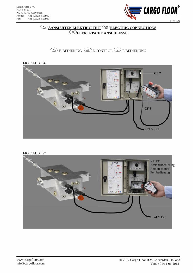
2012 Cargo Floor B.V. Coevorden, Holland
Versie 01/11-01-2012 www.cargofloor.com [email protected]
Cargo Floor B.V. P.O. Box 271 NL-7740 AG Coevorden Phone: +31-(0)524- 593900 Fax: +31-(0)524- 593999
Blz. 58 NL AANSLUITEN ELEKTRICITEIT GB ELECTRIC CONNECTIONS
D ELEKTRISCHE ANSCHLUSSE
NL E-BEDIENING GB E CONTROL D E BEDIENUNG
FIG. / ABB. 26
FIG. / ABB. 27
RX TX Afstandsbediening Remote control Fernbedienung
± 24 V DC
± 24 V DC
CF 7
CF 8
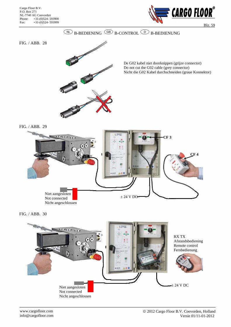
2012 Cargo Floor B.V. Coevorden, Holland
Versie 01/11-01-2012 www.cargofloor.com [email protected]
Cargo Floor B.V. P.O. Box 271 NL-7740 AG Coevorden Phone: +31-(0)524- 593900 Fax: +31-(0)524- 593999
Blz. 59 NL B-BEDIENING GB B-CONTROL D B-BEDIENUNG
FIG. / ABB. 28
FIG. / ABB. 29
FIG. / ABB. 30
De G02 kabel niet doorknippen (grijze connector) Do not cut the G02 cable (grey connector) Nicht die G02 Kabel durchschneiden (graue Konnektor)
± 24 V DC Niet aangesloten Not connected Nicht angeschlossen
RX TX Afstandsbediening Remote control Fernbedienung
± 24 V DCNiet aangesloten Not connected Nicht angeschlossen
CF 3
CF 4
2012 Cargo Floor B.V. Coevorden, Holland
Versie 01/11-01-2012 www.cargofloor.com [email protected]
Cargo Floor B.V. P.O. Box 271 NL-7740 AG Coevorden Phone: +31-(0)524- 593900 Fax: +31-(0)524- 593999
Blz. 60
NL OMBOUW BEDIENING
Om na uitlevering van het voertuig een eventuele ombouw van een B naar een E bediening te vergemakkelijken word er bij een B bediening standaard de E bedieningschakelkast (CF 7 / CF 8 meegeleverd. Deze is voorzien van een andere bestickering en bepaalde schakelfuncties die niet actief zijn. Het is hierbij belangrijk dat de waterdichte afgeplugde kabel wel wordt gemonteerd, maar niet kan en hoeft te worden aangesloten. Deze dient in de buurt van het besturingsventiel te worden vastgeklemd aan bijvoorbeeld de GS02 kabel. De gemonteerde waterdichte plug mag niet verwijderd worden. Bij de ombouw naar een E bediening kan na de montage van de G02 magneet de waterdichte plug worden verwijdert en kan de steker worden aangesloten op deze magneet. De stickers op de schakelaar moet wel vervangen worden, zodat de bedieningsuitleg overeenkomt met de gekozen E of B bediening.
GB TRANSFORMING THE CONTROL To simplify the eventual modifying of a B control to a E control after delivery of the vehicle an E control box (CF7 / CF8) is supplied as a standard with the B control. This control is equipped with other stickers and certain switching function are not active. It is important that the watertight capped cable is mounted, but can not, and does not have to be connected. The cable needs to be clamped in the vicinity of the control valve, onto for example the GS02 cable. The premounted watertight plug may not be removed. After the mounting the G02 solenoid, when converting an B to an E control, the watertight plug can be removed and the plug can be connected to this solenoid.
The stickers on the switch must be replaced, so the control explanation does match the chosen E or B control.
D UMBAU BEDIENUNG Um ein eventueller Umbau von B zu E nach Lieferung des Fahrzeugs zu vereinfachen wird bei einer B Bedienung Standard das E Schaltgehäuse (CF 7 / CF 8) mitgeliefert. Diese ist versehen mit anderen Aufkleber und bestimmte Schaltfunktionen sind nicht aktiv. Hierbei ist es wichtig dass das wasserdicht abgedichtete Kabel wohl montiert wird, aber nicht kann, und nicht braucht angeschlossen werden. Diese soll in der Nähe des Steuerungsventils festgeklemmt werden, zum Beispiel an dem GS02 Kabel. Der montierte wasserdichte Stöpsel darf nicht entfernt werden. Bei einem Umbau zu E Bedienung kann nach der Montage der G02 Spule der wasserdichte Stöpsel entfernt werden und der Stecker angeschlossen werden auf diese Spule. Die Aufkleber auf dem Schalter sollen ausgewechselt werden, so dass die Bedienungserklärung übereinstimmt mit der gewählten E oder B Bedienung.
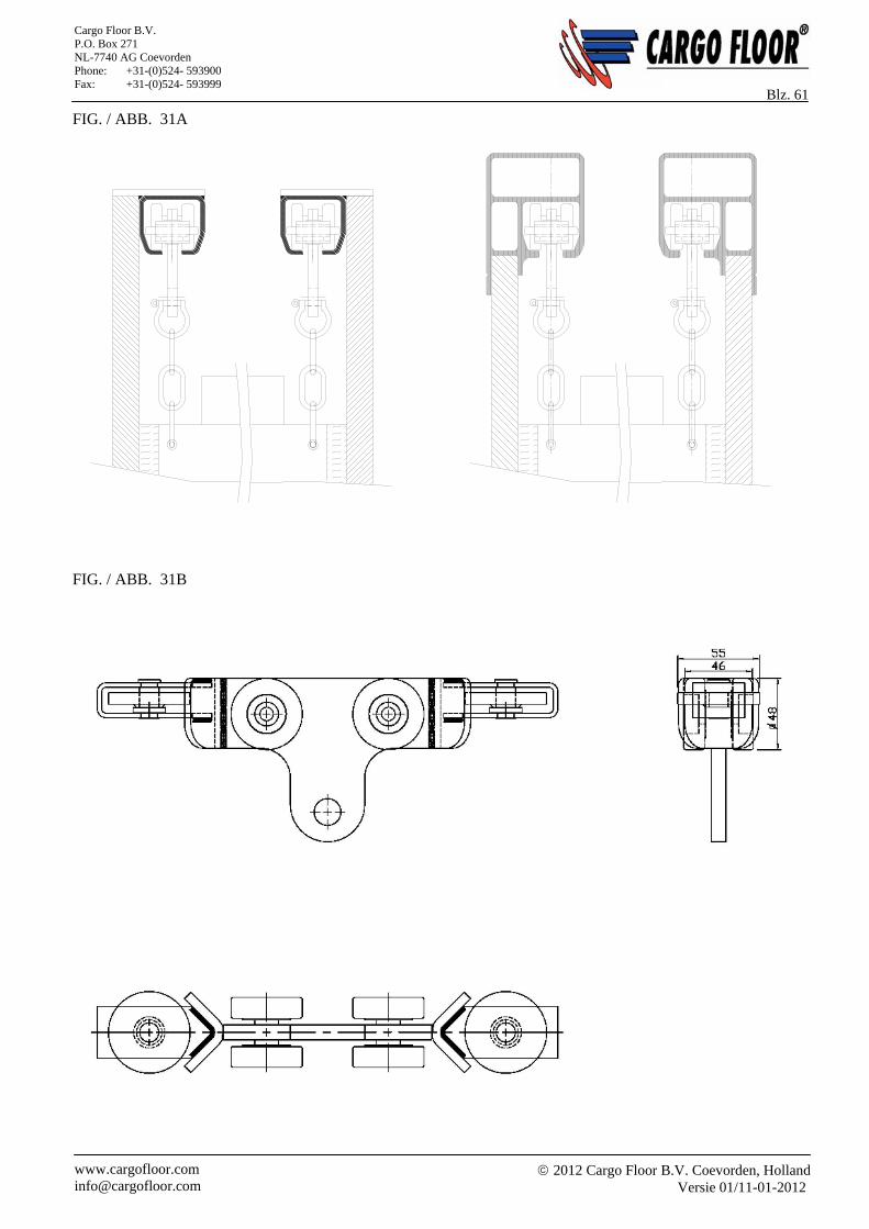
2012 Cargo Floor B.V. Coevorden, Holland
Versie 01/11-01-2012 www.cargofloor.com [email protected]
Cargo Floor B.V. P.O. Box 271 NL-7740 AG Coevorden Phone: +31-(0)524- 593900 Fax: +31-(0)524- 593999
Blz. 61 FIG. / ABB. 31A
FIG. / ABB. 31B
2012 Cargo Floor B.V. Coevorden, Holland
Versie 01/11-01-2012 www.cargofloor.com [email protected]
Cargo Floor B.V. P.O. Box 271 NL-7740 AG Coevorden Phone: +31-(0)524- 593900 Fax: +31-(0)524- 593999
Blz. 62
NL HET MEELOPEND KOPSCHOT Het meelopend kopschot kan worden gemaakt van zijwandprofielen versterkt met een randprofiel. Daarnaast is het ook mogelijk een frame met daarin een gespannen doek als meelopend kopschot te gebruiken. Het kopschot kan het beste met twee Cargo Rollers, Heavy Duty, 6 wielen, rail clean (artikelnummer 5165002), zie figuur 31A, in rails, welke aan de bovenrand van de bak dienen te worden gemonteerd, worden opgehangen. Veel aluminium bovenranden hebben deze rail reeds geïntegreerd in het bovenrandprofiel. Monteer de rails evenwijdig met de vloer van de wagen. De bevestiging van het schot aan de Cargo Roller dient te bestaan uit drie kettingschakels, zodat het schot zich vrij kan bewegen en de Cargo Rollers niet vast kunnen lopen. Tussen het kopschot en de zijwanden kan men borstels of rubber flappen aanbrengen tegen eventuele lekkage en om de zijwanden schoon te houden. Schot aan weerszijden ca. 25-30 mm vrij laten lopen van de zijwanden. Zijwanden ontdoen van obstakels (zoals lassen ed.).
GB THE SLIDING BULKHEAD The sliding bulkhead can be made from sidewall profiles reinforced by an edge profile. It is also possible to use a frame with a taut tarpaulin as a sliding bulkhead. It is best to hang the bulkhead from two Cargo Rollers, Heavy Duty, 6 wheel, rail clean in rails (part number 5165002), see figure 31A, mounted on the top edge of the container. Many aluminium top edges have this rail already integrated. Mount the rails at the same width as the width of the carriage. The bulkhead needs to be fastened to the Cargo Roller via lengths of chain (3 links), so that the bulkhead can move freely and the Cargo Rollers won’t jam. Brushes or rubber flaps can be mounted between the bulkhead and the sidewalls to avoid leakage and to keep the sidewalls clean. Let the head run free on both sides of the side walls, about 25-30 mm. take obstacles (like welding ed) of the sidewalls.
D MITLAUFENDE STIRNWAND Die mitlaufende Stirnwand kann aus Seitenwandprofilen, verstärkt mit einem Randprofil, hergestellt werden. Außerdem besteht die Möglichkeit, einen Rahmen mit einem darin gespannten Tuch als mitlaufende Stirnwand einzusetzen. Die Stirnwand kann am besten mit zwei Cargo Roller, Schwerlast, 6 Rad, Schienen Reiniger (Ersatzteilnummer 5165002), sehe Abb. 31A, in Schienen aufgehängt werden, die an der Oberkante des Behälters montiert werden müssen. Viele Aluminium-Oberkanten weisen diese in das Oberrandprofil integrierte Schiene bereits auf. Montieren Sie die Schienen parallel zum Boden des Wagens. Die Befestigung der Stirnwand an den Cargo Roller muss aus drei Kettengliedern bestehen, so dass sich die Stirnwand frei bewegen kann und die Cargo Roller nicht festgehen können. Zwischen der Stirnwand und den Seitenwänden können Borsten oder Gummilappen als Sicherung gegen mögliches Auslaufen (Lecks) angebracht werden. Außerdem werden die Seitenwände so sauber gehalten. Lass der Wand frei laufen von den Seitenwande, etwa 25-30 mm. Hindernisse wie Verschweißungen von die Seitenwande entfernen.
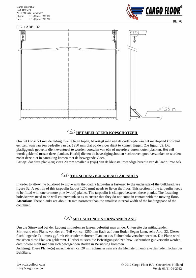
2012 Cargo Floor B.V. Coevorden, Holland
Versie 01/11-01-2012 www.cargofloor.com [email protected]
Cargo Floor B.V. P.O. Box 271 NL-7740 AG Coevorden Phone: +31-(0)524- 593900 Fax: +31-(0)524- 593999
Blz. 63 FIG. / ABB. 32
NL HET MEELOPEND KOPSCHOTZEIL Om het kopschot met de lading mee te laten lopen, bevestigt men aan de onderzijde van het meelopend kopschot een zeil waarvan een gedeelte van ca. 1250 mm plat op de vloer dient te kunnen liggen. Zie figuur 32. Dit platliggende gedeelte dient eventueel te worden voorzien van één of meerdere vurenhouten planken. Het zeil wordt geklemd tussen deze planken. Hierbij dienen de bevestigingsbouten / schroeven goed verzonken te worden zodat deze niet in aanraking komen met de bewegende vloer. Let op: dat deze plank(en) circa 20 mm smaller is (zijn) dan de kleinste inwendige breedte van de laadruimte bak.
GB THE SLIDING BULKHEAD TARPAULIN
In order to allow the bulkhead to move with the load, a tarpaulin is fastened to the underside of the bulkhead, see figure 32. A section of this tarpaulin (about 1250 mm) needs to lie on the floor. This section of the tarpaulin needs to be fitted with one or more pine (wood) planks. The tarpaulin is clamped between these planks. The fastening bolts/screws need to be well countersunk so as to ensure that they do not come in contact with the moving floor. Attention: These planks are about 20 mm narrower than the smallest internal width of the loadingspace of the container.
D MITLAUFENDE STIRNWANDPLANE Um die Stirnwand bei der Ladung mitlaufen zu lassen, befestigt man an der Unterseite der mitlaufenden Stirnwand eine Plane, von der ein Teil von ca. 1250 mm flach auf dem Boden liegen kann, sehe Abb. 32. Dieser flach liegende Teil muss ggf. mit einer oder mehreren Planken aus Fichtenholz versehen werden. Die Plane wird zwischen diese Planken geklemmt. Hierbei müssen die Befestigungsbolzen bzw. -schrauben gut versenkt werden, damit diese nicht mit dem sich bewegenden Boden in Berührung kommen. Achtung: Diese Planke(n) muss/müssen ca. 20 mm schmaler sein als die kleinste Innenbreite des ladenflaches des Behälters.
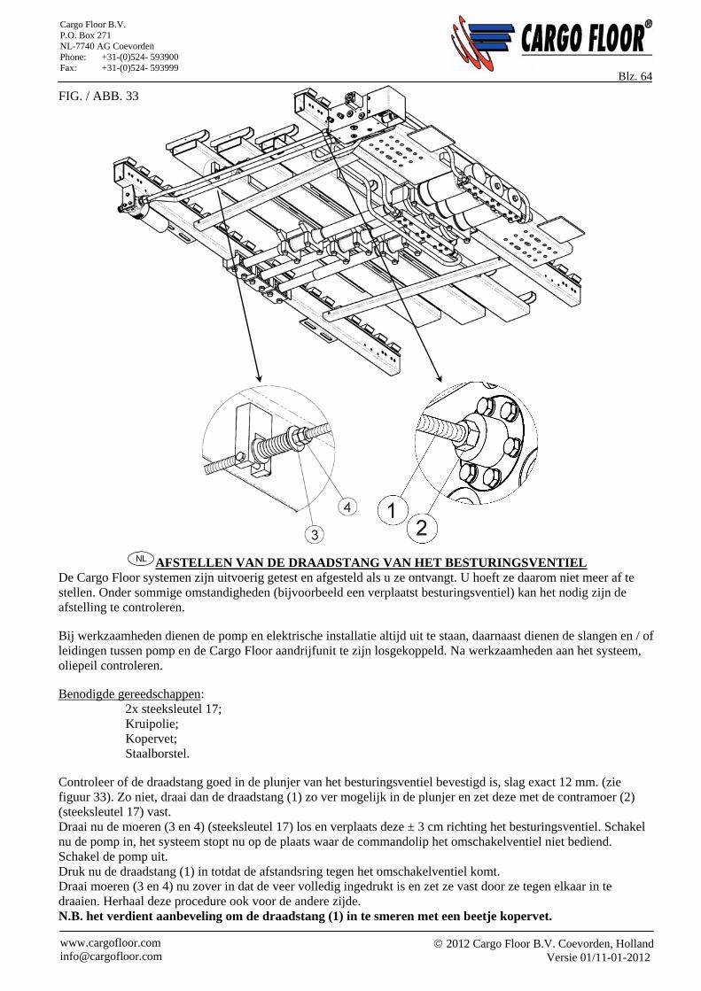
2012 Cargo Floor B.V. Coevorden, Holland
Versie 01/11-01-2012 www.cargofloor.com [email protected]
Cargo Floor B.V. P.O. Box 271 NL-7740 AG Coevorden Phone: +31-(0)524- 593900 Fax: +31-(0)524- 593999
Blz. 64 FIG. / ABB. 33
NL AFSTELLEN VAN DE DRAADSTANG VAN HET BESTURINGSVENTIEL De Cargo Floor systemen zijn uitvoerig getest en afgesteld als u ze ontvangt. U hoeft ze daarom niet meer af te stellen. Onder sommige omstandigheden (bijvoorbeeld een verplaatst besturingsventiel) kan het nodig zijn de afstelling te controleren. Bij werkzaamheden dienen de pomp en elektrische installatie altijd uit te staan, daarnaast dienen de slangen en / of leidingen tussen pomp en de Cargo Floor aandrijfunit te zijn losgekoppeld. Na werkzaamheden aan het systeem, oliepeil controleren. Benodigde gereedschappen: 2x steeksleutel 17; Kruipolie; Kopervet; Staalborstel. Controleer of de draadstang goed in de plunjer van het besturingsventiel bevestigd is, slag exact 12 mm. (zie figuur 33). Zo niet, draai dan de draadstang (1) zo ver mogelijk in de plunjer en zet deze met de contramoer (2) (steeksleutel 17) vast. Draai nu de moeren (3 en 4) (steeksleutel 17) los en verplaats deze ± 3 cm richting het besturingsventiel. Schakel nu de pomp in, het systeem stopt nu op de plaats waar de commandolip het omschakelventiel niet bediend. Schakel de pomp uit. Druk nu de draadstang (1) in totdat de afstandsring tegen het omschakelventiel komt. Draai moeren (3 en 4) nu zover in dat de veer volledig ingedrukt is en zet ze vast door ze tegen elkaar in te draaien. Herhaal deze procedure ook voor de andere zijde. N.B. het verdient aanbeveling om de draadstang (1) in te smeren met een beetje kopervet.
2012 Cargo Floor B.V. Coevorden, Holland
Versie 01/11-01-2012 www.cargofloor.com [email protected]
Cargo Floor B.V. P.O. Box 271 NL-7740 AG Coevorden Phone: +31-(0)524- 593900 Fax: +31-(0)524- 593999
Blz. 65
GB ADJUSTMENT OF THE THREADED ROD OF THE STEERING VALVE. The Cargo Floor systems are already adjusted and tested when you take them over. You therefore do not need to adjust them anymore, but in certain circumstances (moved combination valve) it may be necessary to check the adjustment. The pump and electrical installation must always be switched-off when working on the system; in addition, the hoses and/or pipelines between the pump and the Cargo Floor should also be disconnected. Check the oil level after when the work on the system is done. Necessary tools: 2x spanner 17; High viscosity oil; Copper grease; Steel brush. Check that the wire rod is fastened securely to the steering valve, stroke exactly 12 mm (see figure 33). If not, then screw the wire rod (1) as far as possible into the plunger and secure this with the contra nut (2) (spanner size 17). Loosen nuts (3 and 4, spanner size 17) and move these about 3 cm in the direction of the steering valve. Now switch the pump on. The system will stop now at the point where the command lip no longer operates the switchover valve. Switch off the pump. Now push the wire rod (1) in until the spacer ring touches the switchover valve. Tighten nuts (3 and 4) so that the spring is fully pushed in, and secure them by tightening them against one another. Repeat this procedure for the other side. N.B. It is worthwhile spreading some copper grease on the wire rod (1).
D DAS EINSTELLEN DER GEWINDESTANGE DES STEUERVENTILES Die Cargo Floor Systeme sind bei der Auslieferung geprüft und eingestellt. Sie brauchen diese deswegen nicht mehr ein zu stellen, aber unter bestimmten Umständen (versetztes Kombiventil) kann es erforderlich sein, die Einstellung zu überprüfen. Bei Arbeiten müssen die Pumpe und Elektroanlage jederzeit abgeschaltet sein. Weiterhin müssen die Schläuche und / oder Leitungen zwischen der Pumpe und der Cargo-Floor-Antriebseinheit abgekoppelt worden sein. Nach Arbeiten an dem System den Ölstand kontrollieren. Benötigtes Werkzeug: 2x Steckschlüssel 17; Kriechöl; Kupferfett; Stahlbürste. Überprüfen Sie, ob die Gewindestange gut in der Aufnahme (Achse) des Steuerventils befestigt ist, Hub exakt 12 mm. (sehe Abb. 33). Ist dies nicht der Fall, dann drehen Sie die Gewindestange (1) so weit wie möglich in die Aufnahme ein und arretieren Sie die Stange mit der Kontermutter (2) (Steckschlüssel 17). Drehen Sie jetzt die Muttern (3 und 4, Steckschlüssel 17) los und versetzen Sie diese um ± 3 cm in Richtung des Steuerventils. Schalten Sie dann die Pumpe ein. Das System stoppt jetzt an der Stelle, wo die Steuerlippe das Umschaltventil nicht bedient. Schalten Sie die Pumpe aus. Drücken Sie nun die Gewindestange ein, bis der Distanzring gegen das Umschaltventil stößt. Drehen Sie die Muttern (3 und 4) jetzt so weit ein, dass die Feder vollständig eingedruckt ist und arretieren Sie diese, indem Sie sie gegeneinander eindrehen. Wiederholen Sie diesen Vorgang auch für die andere Seite. Hinweis: Wir empfehlen, die Gewindestange (1) mit etwas Kupferfett einzuschmieren.
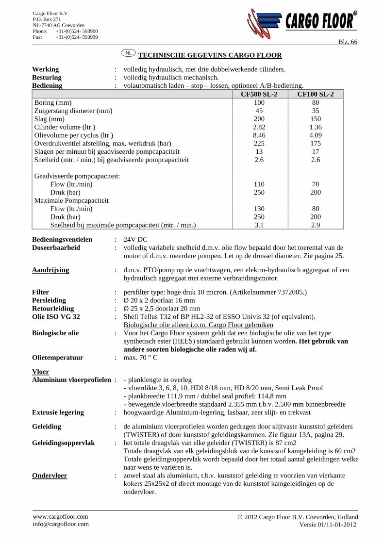
2012 Cargo Floor B.V. Coevorden, Holland
Versie 01/11-01-2012 www.cargofloor.com [email protected]
Cargo Floor B.V. P.O. Box 271 NL-7740 AG Coevorden Phone: +31-(0)524- 593900 Fax: +31-(0)524- 593999
Blz. 66 NL TECHNISCHE GEGEVENS CARGO FLOOR
Werking : volledig hydraulisch, met drie dubbelwerkende cilinders. Besturing : volledig hydraulisch mechanisch. Bediening : volautomatisch laden – stop – lossen, optioneel A/B-bediening. CF500 SL-2 CF100 SL-2 Boring (mm) 100 80 Zuigerstang diameter (mm) 45 35 Slag (mm) 200 150 Cilinder volume (ltr.) 2.82 1.36 Olievolume per cyclus (ltr.) 8.46 4.09 Overdrukventiel afstelling, max. werkdruk (bar) 225 175 Slagen per minuut bij geadviseerde pompcapaciteit 13 17 Snelheid (mtr. / min.) bij geadviseerde pompcapaciteit 2.6 2.6 Geadviseerde pompcapaciteit: Flow (ltr./min) 110 70 Druk (bar) 250 200 Maximale Pompcapaciteit Flow (ltr./min) 130 80 Druk (bar) 250 200 Snelheid bij maximale pompcapaciteit (mtr. / min.) 3.1 2.9
Bedieningsventielen : 24V DC Doseerbaarheid : volledig variabele snelheid d.m.v. olie flow bepaald door het toerental van de
motor of d.m.v. meerdere pompen. Let op de drossel diameter. Zie pagina 25.
Aandrijving : d.m.v. PTO/pomp op de vrachtwagen, een elektro-hydraulisch aggregaat of een hydraulisch aggregaat met externe verbrandingsmotor.
Filter : persfilter type: hoge druk 10 micron. (Artikelnummer 7372005.) Persleiding : Ø 20 x 2 doorlaat 16 mm Retourleiding : Ø 25 x 2,5 doorlaat 20 mm Olie ISO VG 32 : Shell Tellus T32 of BP HL2-32 of ESSO Univis 32 (of equivalent). Biologische olie alleen i.o.m. Cargo Floor gebruiken Biologische olie : Voor het Cargo Floor systeem geldt dat een biologische olie van het type
synthetisch ester (HEES) standaard gebruikt kunnen worden. Het gebruik van andere soorten biologische olie raden wij af.
Olietemperatuur : max. 70 ° C
Vloer Aluminium vloerprofielen : - planklengte in overleg
- vloerdikte 3, 6, 8, 10, HDI 8/18 mm, HD 8/20 mm, Semi Leak Proof - plankbreedte 111,9 mm / dubbel seal profiel: 114,8 mm
- bewegende vloerbreedte standaard 2.355 mm t.b.v. 2.500 mm binnenbreedte Extrusie legering : hoogwaardige Aluminium-legering, lasbaar, zeer slijt- en trekvast
Geleiding : de aluminium vloerprofielen worden gedragen door slijtvaste kunststof geleiders (TWISTER) of door kunststof geleidingskammen. Zie figuur 13A, pagina 29.
Geleidingsoppervlak : het totale draagvlak van elke geleider (TWISTER) is 87 cm2 Totale draagvlak van elk geleidingsblok van de kunststof kamgeleiding is 60 cm2
Totale geleidingsoppervlak wordt bepaald door het totaal aantal geleidingen welke naar wens te variëren is.
Ondervloer : zowel staal als aluminium, t.b.v. kunststof geleiding te voorzien van vierkante kokers 25x25x2 of direct montage van de kunststof kamgeleidingen op de ondervloer.
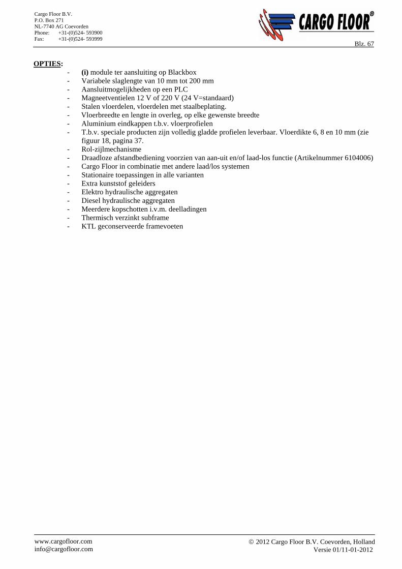
2012 Cargo Floor B.V. Coevorden, Holland
Versie 01/11-01-2012 www.cargofloor.com [email protected]
Cargo Floor B.V. P.O. Box 271 NL-7740 AG Coevorden Phone: +31-(0)524- 593900 Fax: +31-(0)524- 593999
Blz. 67 OPTIES:
- (i) module ter aansluiting op Blackbox - Variabele slaglengte van 10 mm tot 200 mm - Aansluitmogelijkheden op een PLC - Magneetventielen 12 V of 220 V (24 V=standaard) - Stalen vloerdelen, vloerdelen met staalbeplating. - Vloerbreedte en lengte in overleg, op elke gewenste breedte - Aluminium eindkappen t.b.v. vloerprofielen - T.b.v. speciale producten zijn volledig gladde profielen leverbaar. Vloerdikte 6, 8 en 10 mm (zie
figuur 18, pagina 37. - Rol-zijlmechanisme - Draadloze afstandbediening voorzien van aan-uit en/of laad-los functie (Artikelnummer 6104006) - Cargo Floor in combinatie met andere laad/los systemen - Stationaire toepassingen in alle varianten - Extra kunststof geleiders - Elektro hydraulische aggregaten - Diesel hydraulische aggregaten - Meerdere kopschotten i.v.m. deelladingen - Thermisch verzinkt subframe - KTL geconserveerde framevoeten
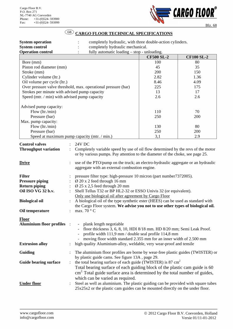
2012 Cargo Floor B.V. Coevorden, Holland
Versie 01/11-01-2012 www.cargofloor.com [email protected]
Cargo Floor B.V. P.O. Box 271 NL-7740 AG Coevorden Phone: +31-(0)524- 593900 Fax: +31-(0)524- 593999
Blz. 68 GB CARGO FLOOR TECHNICAL SPECIFICATIONS
System operation : completely hydraulic, with three double-action cylinders. System control : completely hydraulic mechanical. Operation control : fully automatic loading – stop - unloading. CF500 SL-2 CF100 SL-2 Bore (mm) 100 80 Piston rod diameter (mm) 45 35 Stroke (mm) 200 150 Cylinder volume (ltr.) 2.82 1.36 Oil volume per cycle (ltr.) 8.46 4.09 Over pressure valve threshold, max. operational pressure (bar) 225 175 Strokes per minute with advised pump capacity 13 17 Speed (mtr. / min) with advised pump capacity 2.6 2.6
Advised pump capacity: Flow (ltr./min) 110 70 Pressure (bar) 250 200 Max. pump capacity: Flow (ltr./min) 130 80 Pressure (bar) 250 200 Speed at maximum pump capacity (mtr. / min.) 3,1 2.9
Control valves : 24V DC Throughput variation : Completely variable speed by use of oil flow determined by the revs of the motor
or by various pumps. Pay attention to the diameter of the choke, see page 25.
Drive : use of the PTO/pump on the truck; an electro-hydraulic aggregate or an hydraulic aggregate with an external combustion engine.
Filter : pressure filter type: high-pressure 10 micron (part number7372005). Pressure piping : Ø 20 x 2 feed through 16 mm Return piping : Ø 25 x 2,5 feed through 20 mm Oil ISO VG 32 b.v. : Shell Tellus T32 or BP HL2-32 or ESSO Univis 32 (or equivalent). Only use biological oil after agreement by Cargo Floor Biological oil : A biological oil of the type synthetic ester (HEES) can be used as standard with
the Cargo Floor system. We advise you not to use other types of biological oil. Oil temperature : max. 70 ° C
Floor Aluminium floor profiles : - plank length negotiable - floor thickness 3, 6, 8, 10, HDI 8/18 mm. HD 8/20 mm; Semi Leak Proof. - profile width 111,9 mm / double seal profile 114,8 mm - moving floor width standard 2.355 mm for an inner width of 2.500 mm Extrusion alloy : high quality Aluminium-alloy, weldable, very wear-proof and tensile
Guiding : The aluminium floor profiles are borne by wear-free plastic guides (TWISTER) or by plastic guide cams. See figure 13A , page 29.
Guide bearing surface : the total bearing surface of each guide (TWISTER) is 87 cm2 Total bearing surface of each guiding block of the plastic cam guide is 60
cm2. Total guide surface area is determined by the total number of guides, which can be varied as required.
Under floor : Steel as well as aluminium. The plastic guiding can be provided with square tubes 25x25x2 or the plastic cam guides can be mounted directly on the under floor.
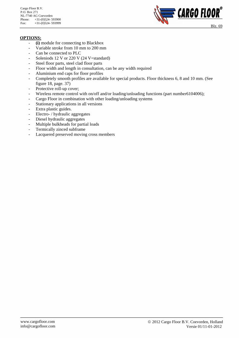
2012 Cargo Floor B.V. Coevorden, Holland
Versie 01/11-01-2012 www.cargofloor.com [email protected]
Cargo Floor B.V. P.O. Box 271 NL-7740 AG Coevorden Phone: +31-(0)524- 593900 Fax: +31-(0)524- 593999
Blz. 69 OPTIONS:
- (i) module for connecting to Blackbox - Variable stroke from 10 mm to 200 mm - Can be connected to PLC - Soleniods 12 V or 220 V (24 V=standard) - Steel floor parts, steel clad floor parts - Floor width and length in consultation, can be any width required - Aluminium end caps for floor profiles - Completely smooth profiles are available for special products. Floor thickness 6, 8 and 10 mm. (See
figure 18, page. 37) - Protective roll-up cover; - Wireless remote control with on/off and/or loading/unloading functions (part number6104006); - Cargo Floor in combination with other loading/unloading systems - Stationary applications in all versions - Extra plastic guides. - Electro- / hydraulic aggregates - Diesel hydraulic aggregates - Multiple bulkheads for partial loads - Termically zinced subframe - Lacquered preserved moving cross members
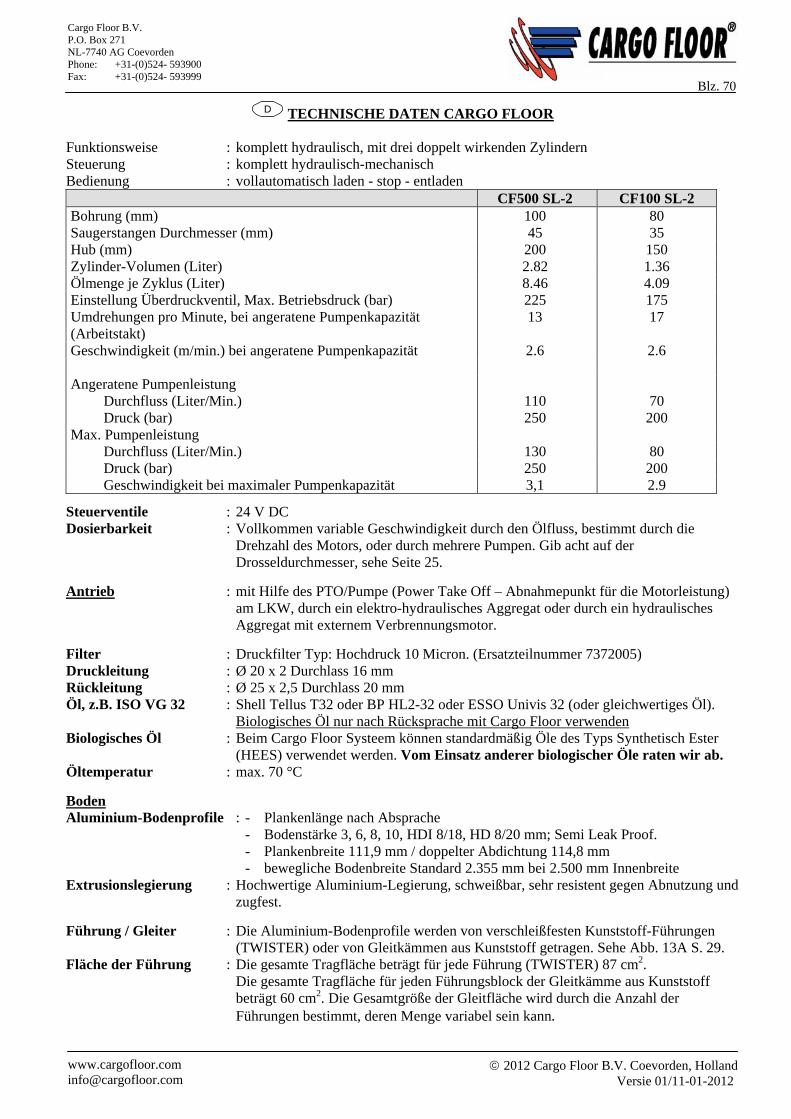
2012 Cargo Floor B.V. Coevorden, Holland
Versie 01/11-01-2012 www.cargofloor.com [email protected]
Cargo Floor B.V. P.O. Box 271 NL-7740 AG Coevorden Phone: +31-(0)524- 593900 Fax: +31-(0)524- 593999
Blz. 70 D TECHNISCHE DATEN CARGO FLOOR
Funktionsweise : komplett hydraulisch, mit drei doppelt wirkenden Zylindern Steuerung : komplett hydraulisch-mechanisch Bedienung : vollautomatisch laden - stop - entladen CF500 SL-2 CF100 SL-2 Bohrung (mm) 100 80 Saugerstangen Durchmesser (mm) 45 35 Hub (mm) 200 150 Zylinder-Volumen (Liter) 2.82 1.36 Ölmenge je Zyklus (Liter) 8.46 4.09 Einstellung Überdruckventil, Max. Betriebsdruck (bar) 225 175 Umdrehungen pro Minute, bei angeratene Pumpenkapazität (Arbeitstakt)
13 17
Geschwindigkeit (m/min.) bei angeratene Pumpenkapazität 2.6 2.6 Angeratene Pumpenleistung Durchfluss (Liter/Min.) 110 70 Druck (bar) 250 200 Max. Pumpenleistung Durchfluss (Liter/Min.) 130 80 Druck (bar) 250 200 Geschwindigkeit bei maximaler Pumpenkapazität 3,1 2.9
Steuerventile : 24 V DC Dosierbarkeit : Vollkommen variable Geschwindigkeit durch den Ölfluss, bestimmt durch die
Drehzahl des Motors, oder durch mehrere Pumpen. Gib acht auf der Drosseldurchmesser, sehe Seite 25.
Antrieb : mit Hilfe des PTO/Pumpe (Power Take Off – Abnahmepunkt für die Motorleistung) am LKW, durch ein elektro-hydraulisches Aggregat oder durch ein hydraulisches Aggregat mit externem Verbrennungsmotor.
Filter : Druckfilter Typ: Hochdruck 10 Micron. (Ersatzteilnummer 7372005) Druckleitung : Ø 20 x 2 Durchlass 16 mm Rückleitung : Ø 25 x 2,5 Durchlass 20 mm Öl, z.B. ISO VG 32 : Shell Tellus T32 oder BP HL2-32 oder ESSO Univis 32 (oder gleichwertiges Öl). Biologisches Öl nur nach Rücksprache mit Cargo Floor verwenden Biologisches Öl : Beim Cargo Floor Systeem können standardmäßig Öle des Typs Synthetisch Ester
(HEES) verwendet werden. Vom Einsatz anderer biologischer Öle raten wir ab. Öltemperatur : max. 70 °C
Boden Aluminium-Bodenprofile : - Plankenlänge nach Absprache - Bodenstärke 3, 6, 8, 10, HDI 8/18, HD 8/20 mm; Semi Leak Proof. - Plankenbreite 111,9 mm / doppelter Abdichtung 114,8 mm - bewegliche Bodenbreite Standard 2.355 mm bei 2.500 mm Innenbreite Extrusionslegierung : Hochwertige Aluminium-Legierung, schweißbar, sehr resistent gegen Abnutzung und
zugfest.
Führung / Gleiter : Die Aluminium-Bodenprofile werden von verschleißfesten Kunststoff-Führungen (TWISTER) oder von Gleitkämmen aus Kunststoff getragen. Sehe Abb. 13A S. 29.
Fläche der Führung : Die gesamte Tragfläche beträgt für jede Führung (TWISTER) 87 cm2. Die gesamte Tragfläche für jeden Führungsblock der Gleitkämme aus Kunststoff
beträgt 60 cm2. Die Gesamtgröße der Gleitfläche wird durch die Anzahl der Führungen bestimmt, deren Menge variabel sein kann.
2012 Cargo Floor B.V. Coevorden, Holland
Versie 01/11-01-2012 www.cargofloor.com [email protected]
Cargo Floor B.V. P.O. Box 271 NL-7740 AG Coevorden Phone: +31-(0)524- 593900 Fax: +31-(0)524- 593999
Blz. 71 Unterboden : Stahl und Aluminium, um die Kunststoff-Führung mit Vierkantrohren 25 x
25 x 2 zu versehen oder direkte Montage der Gleitkämme aus Kunststoff auf dem Unterboden.
OPTIONEN:
- (i) Module zum Anschluss an die Blackbox - Variable Hublänge von 10 mm bis 200 mm - Anschlussmöglichkeiten an einen PLC - Spulen 12 V oder 220 V (24 V = Standard) - Bodenelemente aus Stahl, Bodenelemente mit Stahlbelag - Bodenbreite und Lange nach Absprache, für jede gewünschte Breite möglich - Aluminium-Endkappen für Bodenprofile - Für Spezialprodukte sind absolut ebene Profile lieferbar. Bodenstärken 6, 8 und 10 mm. (Sehe ABB. 18,
Seite 37) - Aufrollbare Schutzlage - Kabellose Fernbedienung mit An/Aus und/oder Lade- und Entlade-Funktion (Ersatzteilnummer 6104006) - Cargo Floor in Kombination mit anderen Lade-/Entlade-Systemen - Stationäre Lösungen in allen Varianten - Zusätzliche Führungen/Gleiter aus Kunststoff - Elektro-/hydraulische Aggregate - Diesel-hydraulische Aggregate - Mehrere Stirnwande für Teilladungen - Feuerverzinkte Rahmen - KT-Beschichtete bewegliche Quertraversen
2012 Cargo Floor B.V. Coevorden, Holland
Versie 01/11-01-2012 www.cargofloor.com [email protected]
Cargo Floor B.V. P.O. Box 271 NL-7740 AG Coevorden Phone: +31-(0)524- 593900 Fax: +31-(0)524- 593999
Blz. 72 NL ONDERHOUDSVOORSCHRIFTEN
Geef bij overdracht van de oplegger aan de gebruiker altijd een uitgebreide instructie met betrekking tot werking, onderhoud en gebruik van het Cargo Floor Systeem. Geef ten tijde van de overdracht altijd een bedieningshandleiding mee. Mochten de werkzaamheden het inschakelen van de vloer vereisen, dient u er voor te zorgen dat de vloer te allen tijde onmiddellijk kan worden uitgeschakeld. Locaties waar inklemming/beknelling van lichaamsdelen mogelijk is, mogen niet worden benaderd indien het systeem beweegt.
Voor gedetailleerdere uitleg van het uitvoeren van werkzaamheden, verwijzen wij u naar onze internetsite: www.cargofloor.com
Controle door de eindgebruiker na ontvangst van het nieuwe voertuig: Controleert u de verbinding tussen de aluminium vloerprofielen en het Cargo Floor systeem. Dit doet u door een vinger half op de boutkop en half op de plank te leggen terwijl de vloer loopt. Voelt u beweging in de boutverbinding dan moet de bout verwijderd, schoon gemaakt, opnieuw van Loctite en weer gemonteerd worden, of vervangen. Trek de schroeven niet alleen maar na, de Loctiteverbinding wordt dan verbroken. Indien er schroeven los zitten, verwijzen wij u naar onze internetsite: www.cargofloor.com . Controleer dit enkele dagen na ontvangst van de oplegger, na tien ladingen / lossingen en vervolgens na één maand. Specificatie schroeven: M12 x 30 verzonken schroef met binnenzeskant kl.10.9 galv. verz. DIN 7991 (Dacromet). Het aanhaalmoment bedraagt 100 - 140 Nm.
Regelmatige controles door de eindgebruiker: Om een hoge mate van bedrijfszekerheid en een lange levensduur te verkrijgen van uw Cargo Floor systeem, dient u regelmatig de volgende aspecten – nauwkeurig – te controleren:
- De kwaliteit van de olie; deze dient regelmatig verschoond te worden (controle elk ½ jaar)
- Filterelement elk jaar vervangen of frequenter indien nodig
- Olie elke 2 jaar vervangen, of frequenter indien nodig
- De hoeveelheid aanwezige olie in de tank. Om warmteontwikkeling te onderdrukken is de aanwezigheid van minimaal 100 liter olie in de tank vereist. Vanuit de praktijksituatie (hoge flow, frequent laden en lossen) adviseren wij u echter 150 liter olie beschikbaar te hebben. Gebruik een goede hydraulische olie volgens ISO VG 32.
Controleren en eventueel reinigen van de volgende onderdelen:
- Vloerprofielen: zitten ze nog vast, indien nodig schroeven/bouten vervangen!
- Wartels en koppelingen van alle hydraulische componenten controleren en indien nodig natrekken!
- Olietank: door het verwijderen van het tankdeksel, kunt u achtergebleven resten (condens, vuil enz.) van de bodem verwijderen.
- Retour-/persfilter: door het verwijderen van het filterdeksel/-pot kunt u de filterelementen controleren of, eventueel, na ca. 1 jaar vervangen.
- Controleert u de afdichting tussen de 2 vaste vloerprofielen en de bewegende profielen. Indien zich daartussen speling bevindt, stel deze vaste profielen dan bij, zodat de afdichting optimaal blijkt en lekkage via de zijwanden wordt voorkomen.
Dit alles is noodzakelijk om inwendige slijtage te voorkomen (van bv. pomp/cilinders enz.). Nieuwe elementen zijn verkrijgbaar bij uw carrosseriebouwer. Voor de keuze van het juiste type verwijzen wij u naar de “exploded views” op www.cargofloor.com Wij willen hierbij benadrukken dat de vrij geringe kosten van vervanging van vervuilde onderdelen of olie niet opwegen tegen de kosten en ongemak die hieruit kunnen voortvloeien.
- Afstelling van de draadstang van het besturingsventiel; Het is van belang dat het besturingsventiel goed is afgesteld en dat de schakeling plaats vindt volgens de voorschriften. Zie pagina 55.
Ook het reinigen van de vloerdelen met een stoomcleaner behoort tot het regelmatige preventieve onderhoud, met name bij de zgn. SLP profielen is dit een vereiste om de grote goot regelmatig te reinigen.
2012 Cargo Floor B.V. Coevorden, Holland
Versie 01/11-01-2012 www.cargofloor.com [email protected]
Cargo Floor B.V. P.O. Box 271 NL-7740 AG Coevorden Phone: +31-(0)524- 593900 Fax: +31-(0)524- 593999
Blz. 73 GB MAINTENANCE INSTRUCTIONS
When handing over the trailer to the end user always give an extended instruction with regards to operation, maintenance and use of the Cargo Floor system. At the handing over always give a users manual. When works require turning on the floor you should take care of that the floor can be shut down immediately at any time. Places where clamping/clasping of body parts is possible may not be approached when the system is moving. For more detailed explanation of the execution of the works we would like to refer you to our website: www.cargofloor.com Check for the end user after receipt of the new trailer: Check the join between the aluminium floor profiles and the Cargo Floor-system. You do this by placing your finger half on the bolt and half on the floor profile when the floor is operating. If you feel movement in the bolt connection then the bolt should be removed, cleaned, fitted with Loctite and mounted again, or be replaced. Do not simply just tighten the bolts, the Loctite connection will be broken. If bolts are loose, we would like to refer you to our website: www.cargofloor.com . Check this a couple of days after receipt of the trailer, after 10 loads / unloads and after one month. Specifications of the screws: M12 x 30 countersunk screws with hexagon socket, class 10.9, galvanized. DIN 7991 (Dacromet). The torque is 100 – 140 Nm. Regular checks for the enduser: To ensure that your Cargo Floor system operates reliably and has a long life, it is important that you regularly perform careful checks on the following aspects:
- The quality of the oil; this must be cleaned regularly (check every ½ year);
- Replace the filter element every year;
- Change the oil every 2 years, or more frequently if required;
- The level of oil in the tank. In order to prevent heat developing it is required to have at least 100 liters of oil in the tank. Out of practical experience (high flow, frequently loading and unloading) we advise you to have at least 150 liters of oil available. Use a good quality, hydraulic oil in accordance with the ISO VG 32 norm.
Check and, if necessary clean the following components:
- Floor profiles: are they still fixed, replace screws/bolts if necessary!
- Check the ducts and joints of all hydraulic components, and adjust if necessary!
- Oil tank: by taking the lid off the tank, you can remove any remains (condensation, dirt etc.) from the bottom.
- Return-/pressure filter: by removing the filter lid/ chamber you can check the filter element, or after one year replace it.
- Check the seal between the two fixated floor profiles and the moving profiles. If a margin exist in between, then adjust the fixated floor profiles, in order for the sealing to be optimal and leakage via the side walls is prevented.
This is all necessary to avoid internal wear (of the pump/cylinders etc., for example). New filter parts are available at your system builder. For the right type we refer you to our “exploded views” which you can find on our website www.cargofloor.com We want to emphasize that the minimal costs of replacing dirty parts or oil do not match the costs and discomfort that can proceed out of this. - Adjusting the threaded rod of the steering valve; It is important that the steering valve is correctly adjusted and that the switchover moment occurs according to
the procedures. See page 56. Cleaning the floor parts with a steam cleaner is also part of the regular preventative maintenance, especially with the so called SLP profiles this is mandatory to clean the large gulley regularly.
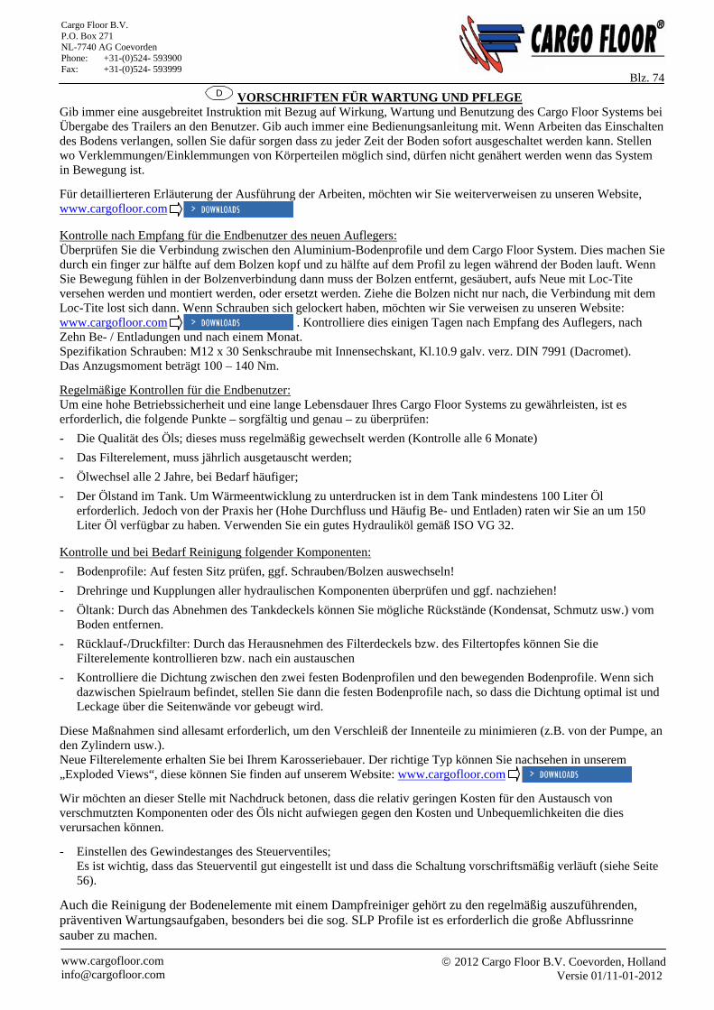
2012 Cargo Floor B.V. Coevorden, Holland
Versie 01/11-01-2012 www.cargofloor.com [email protected]
Cargo Floor B.V. P.O. Box 271 NL-7740 AG Coevorden Phone: +31-(0)524- 593900 Fax: +31-(0)524- 593999
Blz. 74
D VORSCHRIFTEN FÜR WARTUNG UND PFLEGE Gib immer eine ausgebreitet Instruktion mit Bezug auf Wirkung, Wartung und Benutzung des Cargo Floor Systems bei Übergabe des Trailers an den Benutzer. Gib auch immer eine Bedienungsanleitung mit. Wenn Arbeiten das Einschalten des Bodens verlangen, sollen Sie dafür sorgen dass zu jeder Zeit der Boden sofort ausgeschaltet werden kann. Stellen wo Verklemmungen/Einklemmungen von Körperteilen möglich sind, dürfen nicht genähert werden wenn das System in Bewegung ist.
Für detaillierteren Erläuterung der Ausführung der Arbeiten, möchten wir Sie weiterverweisen zu unseren Website, www.cargofloor.com Kontrolle nach Empfang für die Endbenutzer des neuen Auflegers: Überprüfen Sie die Verbindung zwischen den Aluminium-Bodenprofile und dem Cargo Floor System. Dies machen Sie durch ein finger zur hälfte auf dem Bolzen kopf und zu hälfte auf dem Profil zu legen während der Boden lauft. Wenn Sie Bewegung fühlen in der Bolzenverbindung dann muss der Bolzen entfernt, gesäubert, aufs Neue mit Loc-Tite versehen werden und montiert werden, oder ersetzt werden. Ziehe die Bolzen nicht nur nach, die Verbindung mit dem Loc-Tite lost sich dann. Wenn Schrauben sich gelockert haben, möchten wir Sie verweisen zu unseren Website: www.cargofloor.com . Kontrolliere dies einigen Tagen nach Empfang des Auflegers, nach Zehn Be- / Entladungen und nach einem Monat. Spezifikation Schrauben: M12 x 30 Senkschraube mit Innensechskant, Kl.10.9 galv. verz. DIN 7991 (Dacromet). Das Anzugsmoment beträgt 100 – 140 Nm.
Regelmäßige Kontrollen für die Endbenutzer: Um eine hohe Betriebssicherheit und eine lange Lebensdauer Ihres Cargo Floor Systems zu gewährleisten, ist es erforderlich, die folgende Punkte – sorgfältig und genau – zu überprüfen:
- Die Qualität des Öls; dieses muss regelmäßig gewechselt werden (Kontrolle alle 6 Monate)
- Das Filterelement, muss jährlich ausgetauscht werden;
- Ölwechsel alle 2 Jahre, bei Bedarf häufiger;
- Der Ölstand im Tank. Um Wärmeentwicklung zu unterdrucken ist in dem Tank mindestens 100 Liter Öl erforderlich. Jedoch von der Praxis her (Hohe Durchfluss und Häufig Be- und Entladen) raten wir Sie an um 150 Liter Öl verfügbar zu haben. Verwenden Sie ein gutes Hydrauliköl gemäß ISO VG 32.
Kontrolle und bei Bedarf Reinigung folgender Komponenten:
- Bodenprofile: Auf festen Sitz prüfen, ggf. Schrauben/Bolzen auswechseln!
- Drehringe und Kupplungen aller hydraulischen Komponenten überprüfen und ggf. nachziehen!
- Öltank: Durch das Abnehmen des Tankdeckels können Sie mögliche Rückstände (Kondensat, Schmutz usw.) vom Boden entfernen.
- Rücklauf-/Druckfilter: Durch das Herausnehmen des Filterdeckels bzw. des Filtertopfes können Sie die Filterelemente kontrollieren bzw. nach ein austauschen
- Kontrolliere die Dichtung zwischen den zwei festen Bodenprofilen und den bewegenden Bodenprofile. Wenn sich dazwischen Spielraum befindet, stellen Sie dann die festen Bodenprofile nach, so dass die Dichtung optimal ist und Leckage über die Seitenwände vor gebeugt wird.
Diese Maßnahmen sind allesamt erforderlich, um den Verschleiß der Innenteile zu minimieren (z.B. von der Pumpe, an den Zylindern usw.). Neue Filterelemente erhalten Sie bei Ihrem Karosseriebauer. Der richtige Typ können Sie nachsehen in unserem „Exploded Views“, diese können Sie finden auf unserem Website: www.cargofloor.com
Wir möchten an dieser Stelle mit Nachdruck betonen, dass die relativ geringen Kosten für den Austausch von verschmutzten Komponenten oder des Öls nicht aufwiegen gegen den Kosten und Unbequemlichkeiten die dies verursachen können.
- Einstellen des Gewindestanges des Steuerventiles; Es ist wichtig, dass das Steuerventil gut eingestellt ist und dass die Schaltung vorschriftsmäßig verläuft (siehe Seite 56).
Auch die Reinigung der Bodenelemente mit einem Dampfreiniger gehört zu den regelmäßig auszuführenden, präventiven Wartungsaufgaben, besonders bei die sog. SLP Profile ist es erforderlich die große Abflussrinne sauber zu machen.
2012 Cargo Floor B.V. Coevorden, Holland
Versie 01/11-01-2012 www.cargofloor.com [email protected]
Cargo Floor B.V. P.O. Box 271 NL-7740 AG Coevorden Phone: +31-(0)524- 593900 Fax: +31-(0)524- 593999
Blz. 75
NL BELANGRIJKE AANWIJZINGEN - Voorkom dat, bij het afkoppelen van de snelkoppeling of bij het navullen/reinigen van de olietank, vuil en
water in het leidingsysteem komt. - Pas de werksnelheid aan bij bijvoorbeeld het lossen of laden van zware massieve producten waarbij het
systeem de maximale werkdruk benodigd (zie bladzijde 57), dit om hoge belastingen te vermijden. - Het is niet toegestaan om de maximale werkdruk (zie pagina 57) te overschrijden. - Vermijd het laden en lossen van scherpe producten zoals glas zonder rolzeilmechanisme. Dit geeft onnodige
slijtage van de afdichting/profielen. Mocht u deze producten toch veilig willen vervoeren dan adviseren wij u een beschermings-oprolkleedmechanisme te gebruiken.
- Overschrijdt nooit het maximale aantal slagen per min. bij een maximale slag (zie bladzijde 57). Een groter
aantal slagen brengt enorme krachten over in het systeem en het chassis en daarbij wekt het veel warmte in het hydraulische systeem op.
- Bij het laden en lossen van stukgoed is het van belang dat men een gelijkmatige gewichtsverdeling op de vloer
realiseert. Zo niet, dan is de kans aanwezig dat de lading blijft staan. Plaats bij gebruik van pallets zonodig een houten plank van ca. 300 x 18 x 2350 mm multiplex eronder.
GB IMPORTANT INSTRUCTIONS - Avoid letting dirt and water get into the hydraulic system when disconnecting the connectors or when topping
up/cleaning the oil tank. - Adjust the work speed when, for example, heavy massive products are being loaded or unloaded with which
the system needs the maximum power (see page 59), so as to avoid overloading. - It is not permitted to exceed the maximum operational pressure (see page 59).
- Avoid loading and unloading sharp objects such as glass without a protective roll-up cover mechanism. This
causes unnecessary wear of the seal/floorprofiles. If you would like to transport such materials safely, we advise you to use a protective roll-up cover mechanism.
- Never exceed the maximum number of strokes per minute when using the full stroke (see page 59). A greater
number of strokes causes enormous forces in the system and chassis, and causes a lot of heat to be generated in the hydraulic system.
- When loading and unloading packed goods it is important that a good equal weight distribution is realized on
the floor. If this is not the case there is the possibility that the goods won’t move. When using pallets, if necessary, place a wooden plank (of about 300 x 18 x 2350 mm) multiplex underneath.
2012 Cargo Floor B.V. Coevorden, Holland
Versie 01/11-01-2012 www.cargofloor.com [email protected]
Cargo Floor B.V. P.O. Box 271 NL-7740 AG Coevorden Phone: +31-(0)524- 593900 Fax: +31-(0)524- 593999
Blz. 76
D WICHTIGE HINWEISE - Vermeiden Sie, dass beim Öffnen der Schnellkupplung oder beim Nachfüllen/reinigen des Öltanks Schmutz
und Wasser in das Leitungssystem kommt. - Passen Sie die Arbeitsgeschwindigkeit z.B. beim Laden und Entladen von schweren, massiven Produkten an,
bei denen das System den maximalen Arbeitsdruck benötigt (siehe S. 61), und vermeiden Sie so hohe Belastungen.
- Es ist nicht erlaubt, den maximalen Arbeitsdruck (siehe S. 61) zu überschreiten. - Vermeiden Sie das Laden und Entladen von scharfkantigem Material, wie z.B. Glas ohne Aufrollmechanismus
mit einer Schutzlage. Die Abdichtung/Bodenprofile werden dabei unnötig stark angegriffen. Wenn Sie solche Produkte trotzdem sicher transportieren wollen, dann empfehlen wir den Einsatz eines Aufrollmechanismus mit einer Schutzlage.
- Überschreiten Sie niemals die Höchstzahl der zulässigen Arbeitstakte je Minute (siehe S. 61). Eine höhere
Taktzahl stellt eine enorme Belastung für das System und das Chassis dar und erzeugt große Wärme im hydraulischen System.
- Beim Laden und Entladen von Stückgut ist es wichtig, dass eine gute und gleichmäßige Gewichtsverteilung auf
dem Boden realisiert wird. Wenn das nicht der Fall ist, besteht die Möglichkeit, dass die Ware stehen bleibt. Im Bedarfsfall sollten Sie deshalb bei Benutzung einer Palette eine Holzplanke mit den Maßen von ca. 300 x 18 x 2350 mm Schichtholz darunter anbringen.
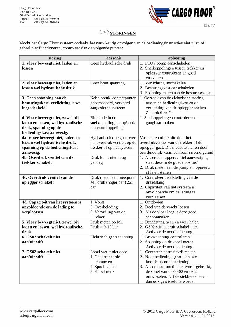
2012 Cargo Floor B.V. Coevorden, Holland
Versie 01/11-01-2012 www.cargofloor.com [email protected]
Cargo Floor B.V. P.O. Box 271 NL-7740 AG Coevorden Phone: +31-(0)524- 593900 Fax: +31-(0)524- 593999
Blz. 77 NL STORINGEN
Mocht het Cargo Floor systeem ondanks het nauwkeurig opvolgen van de bedieningsinstructies niet juist, of geheel niet functioneren, controleer dan de volgende punten:
storing oorzaak oplossing 1. Vloer beweegt niet, laden en lossen
Geen hydraulische druk 1. PTO / pomp aanschakelen 2. Snelkoppelingen tussen trekker en
oplegger controleren en goed vastzetten
2. Vloer beweegt niet, laden en lossen wel hydraulische druk
Geen bron spanning 1. Verlichting inschakelen 2. Besturingskast aanschakelen 3. Spanning meten aan de besturingskast
3. Geen spanning aan de besturingskast, verlichting is wel ingeschakeld
Kabelbreuk, contactpunten gecorrodeerd, verkeerd aangesloten systeem
1. Oorzaak van de elektrische storing tussen de bedieningskast en de verlichting van de oplegger zoeken. Zie ook 6 en 7.
4. Vloer beweegt niet, zowel bij laden en lossen, wel hydraulische druk, spanning op de bedieningskast aanwezig.
Blokkade in de snelkoppeling, let op! ook de retourkoppeling
1. Snelkoppelingen controleren en gangbaar maken
4a. Vloer beweegt niet, laden en lossen wel hydraulische druk, spanning op de bedieningskast aanwezig.
Hydraulisch olie gaat over het overdruk ventiel, op de trekker of op het systeem
Vaststellen of de olie door het overdrukventiel van de trekker of de oplegger gaat. Dit is vast te stellen door een duidelijk waarneembaar sissend geluid
4b. Overdruk ventiel van de trekker schakelt
Druk komt niet hoog genoeg
1. Als er een kipperventiel aanwezig is, staat deze in de goede positie?
2. Druk meten aan de pomp en opnieuw af laten stellen
4c. Overdruk ventiel van de oplegger schakelt
Druk meten aan meetpunt M1 druk (hoger dan) 225 bar
1. Controleer de afstelling van de draadstang
2. Capaciteit van het systeem is onvoldoende om de lading te verplaatsen
4d. Capaciteit van het systeem is onvoldoende om de lading te verplaatsen
1. Vorst 2. Overbelading 3. Vervuiling van de vloer
1. Ontdooien 2. Deel van de vracht lossen 3. Als de vloer leeg is deze goed
schoonmaken 5. Vloer beweegt niet, zowel bij laden en lossen, wel hydraulische druk
Druk meten op M1 Druk = 0-10 bar
1. Draadstang heen en weer halen 2. GS02 stift aan/uit schakelt niet
Activeer de noodbediening 6. GS02 schakelt niet aan/uit stift
Elektrisch geen spanning 1. Bronspanning controleren 2. Spanning op de spoel meten
Activeer de noodbediening 7. GS02 schakelt niet aan/uit stift
Spoel werkt niet door, 1. Gecorrodeerde contacten 2. Spoel kapot 3. Kabelbreuk
1. Contacten corrosievrij maken 2. Noodbediening gebruiken, zie
hoofdstuk noodbediening 3. Als de laadfunctie niet wordt gebruikt,
de spoel van de GS02 en G02 omwisselen, NB de stekkers dienen dan ook gewisseld te worden
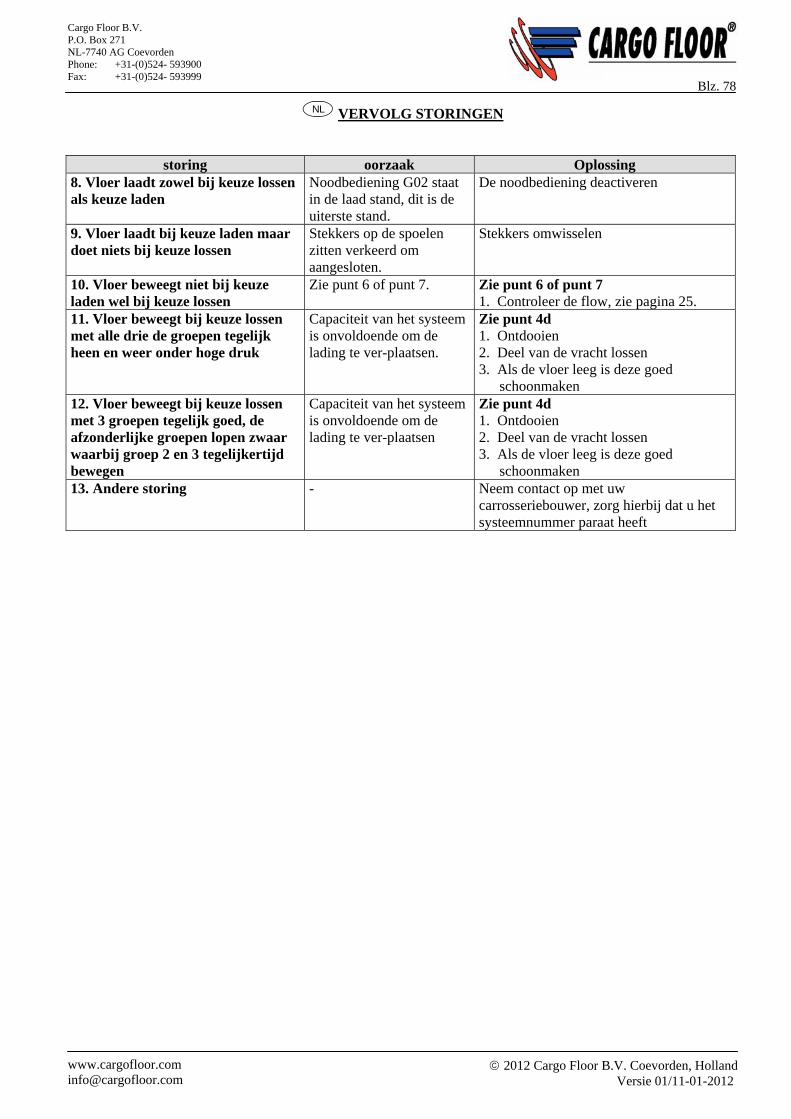
2012 Cargo Floor B.V. Coevorden, Holland
Versie 01/11-01-2012 www.cargofloor.com [email protected]
Cargo Floor B.V. P.O. Box 271 NL-7740 AG Coevorden Phone: +31-(0)524- 593900 Fax: +31-(0)524- 593999
Blz. 78 NL VERVOLG STORINGEN
storing oorzaak Oplossing 8. Vloer laadt zowel bij keuze lossen als keuze laden
Noodbediening G02 staat in de laad stand, dit is de uiterste stand.
De noodbediening deactiveren
9. Vloer laadt bij keuze laden maar doet niets bij keuze lossen
Stekkers op de spoelen zitten verkeerd om aangesloten.
Stekkers omwisselen
10. Vloer beweegt niet bij keuze laden wel bij keuze lossen
Zie punt 6 of punt 7. Zie punt 6 of punt 7 1. Controleer de flow, zie pagina 25.
11. Vloer beweegt bij keuze lossen met alle drie de groepen tegelijk heen en weer onder hoge druk
Capaciteit van het systeem is onvoldoende om de lading te ver-plaatsen.
Zie punt 4d 1. Ontdooien 2. Deel van de vracht lossen 3. Als de vloer leeg is deze goed
schoonmaken 12. Vloer beweegt bij keuze lossen met 3 groepen tegelijk goed, de afzonderlijke groepen lopen zwaar waarbij groep 2 en 3 tegelijkertijd bewegen
Capaciteit van het systeem is onvoldoende om de lading te ver-plaatsen
Zie punt 4d 1. Ontdooien 2. Deel van de vracht lossen 3. Als de vloer leeg is deze goed
schoonmaken 13. Andere storing - Neem contact op met uw
carrosseriebouwer, zorg hierbij dat u het systeemnummer paraat heeft
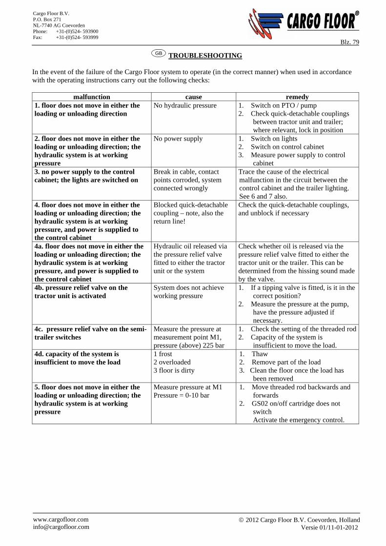
2012 Cargo Floor B.V. Coevorden, Holland
Versie 01/11-01-2012 www.cargofloor.com [email protected]
Cargo Floor B.V. P.O. Box 271 NL-7740 AG Coevorden Phone: +31-(0)524- 593900 Fax: +31-(0)524- 593999
Blz. 79 GB TROUBLESHOOTING
In the event of the failure of the Cargo Floor system to operate (in the correct manner) when used in accordance with the operating instructions carry out the following checks:
malfunction cause remedy 1. floor does not move in either the loading or unloading direction
No hydraulic pressure 1. Switch on PTO / pump 2. Check quick-detachable couplings
between tractor unit and trailer; where relevant, lock in position
2. floor does not move in either the loading or unloading direction; the hydraulic system is at working pressure
No power supply 1. Switch on lights 2. Switch on control cabinet 3. Measure power supply to control
cabinet 3. no power supply to the control cabinet; the lights are switched on
Break in cable, contact points corroded, system connected wrongly
Trace the cause of the electrical malfunction in the circuit between the control cabinet and the trailer lighting. See 6 and 7 also.
4. floor does not move in either the loading or unloading direction; the hydraulic system is at working pressure, and power is supplied to the control cabinet
Blocked quick-detachable coupling – note, also the return line!
Check the quick-detachable couplings, and unblock if necessary
4a. floor does not move in either the loading or unloading direction; the hydraulic system is at working pressure, and power is supplied to the control cabinet
Hydraulic oil released via the pressure relief valve fitted to either the tractor unit or the system
Check whether oil is released via the pressure relief valve fitted to either the tractor unit or the trailer. This can be determined from the hissing sound made by the valve.
4b. pressure relief valve on the tractor unit is activated
System does not achieve working pressure
1. If a tipping valve is fitted, is it in the correct position?
2. Measure the pressure at the pump, have the pressure adjusted if necessary.
4c. pressure relief valve on the semi-trailer switches
Measure the pressure at measurement point M1, pressure (above) 225 bar
1. Check the setting of the threaded rod2. Capacity of the system is
insufficient to move the load. 4d. capacity of the system is insufficient to move the load
1 frost 2 overloaded 3 floor is dirty
1. Thaw 2. Remove part of the load 3. Clean the floor once the load has
been removed 5. floor does not move in either the loading or unloading direction; the hydraulic system is at working pressure
Measure pressure at M1 Pressure = 0-10 bar
1. Move threaded rod backwards and forwards
2. GS02 on/off cartridge does not switch Activate the emergency control.
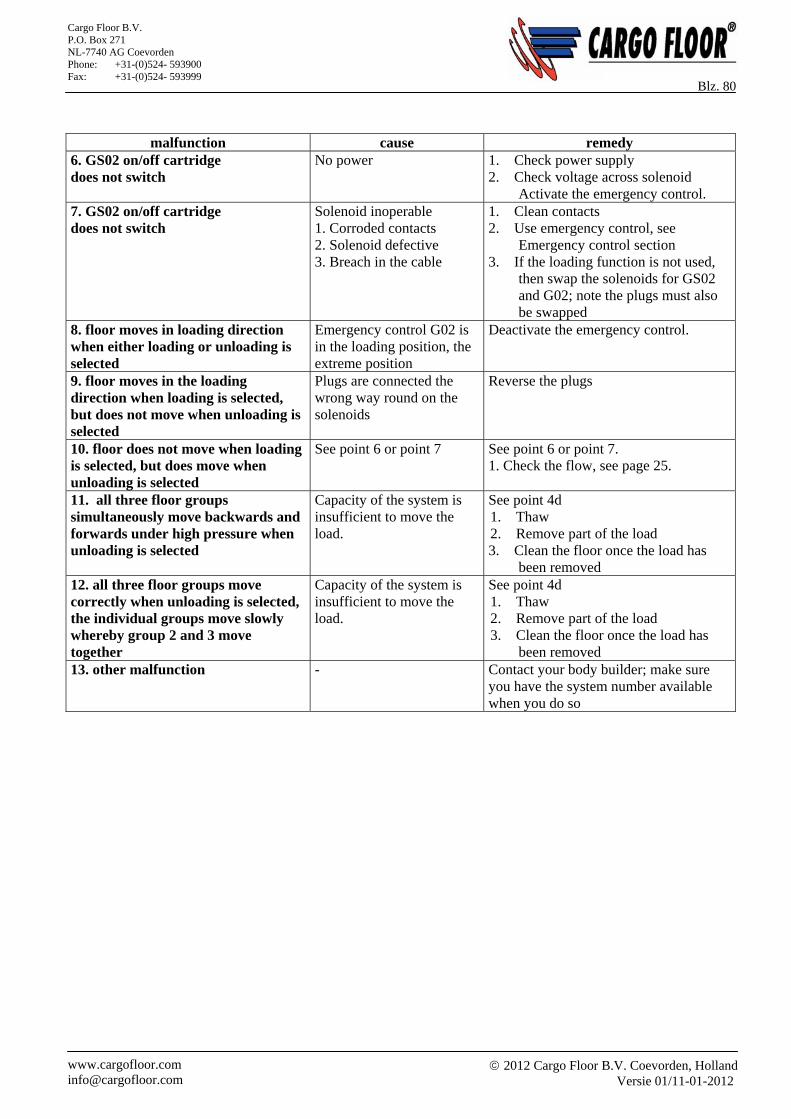
2012 Cargo Floor B.V. Coevorden, Holland
Versie 01/11-01-2012 www.cargofloor.com [email protected]
Cargo Floor B.V. P.O. Box 271 NL-7740 AG Coevorden Phone: +31-(0)524- 593900 Fax: +31-(0)524- 593999
Blz. 80
malfunction cause remedy 6. GS02 on/off cartridge does not switch
No power 1. Check power supply 2. Check voltage across solenoid
Activate the emergency control. 7. GS02 on/off cartridge does not switch
Solenoid inoperable 1. Corroded contacts 2. Solenoid defective 3. Breach in the cable
1. Clean contacts 2. Use emergency control, see
Emergency control section 3. If the loading function is not used,
then swap the solenoids for GS02 and G02; note the plugs must also be swapped
8. floor moves in loading direction when either loading or unloading is selected
Emergency control G02 is in the loading position, the extreme position
Deactivate the emergency control.
9. floor moves in the loading direction when loading is selected, but does not move when unloading is selected
Plugs are connected the wrong way round on the solenoids
Reverse the plugs
10. floor does not move when loading is selected, but does move when unloading is selected
See point 6 or point 7 See point 6 or point 7. 1. Check the flow, see page 25.
11. all three floor groups simultaneously move backwards and forwards under high pressure when unloading is selected
Capacity of the system is insufficient to move the load.
See point 4d 1. Thaw 2. Remove part of the load 3. Clean the floor once the load has
been removed 12. all three floor groups move correctly when unloading is selected, the individual groups move slowly whereby group 2 and 3 move together
Capacity of the system is insufficient to move the load.
See point 4d 1. Thaw 2. Remove part of the load 3. Clean the floor once the load has
been removed 13. other malfunction - Contact your body builder; make sure
you have the system number available when you do so
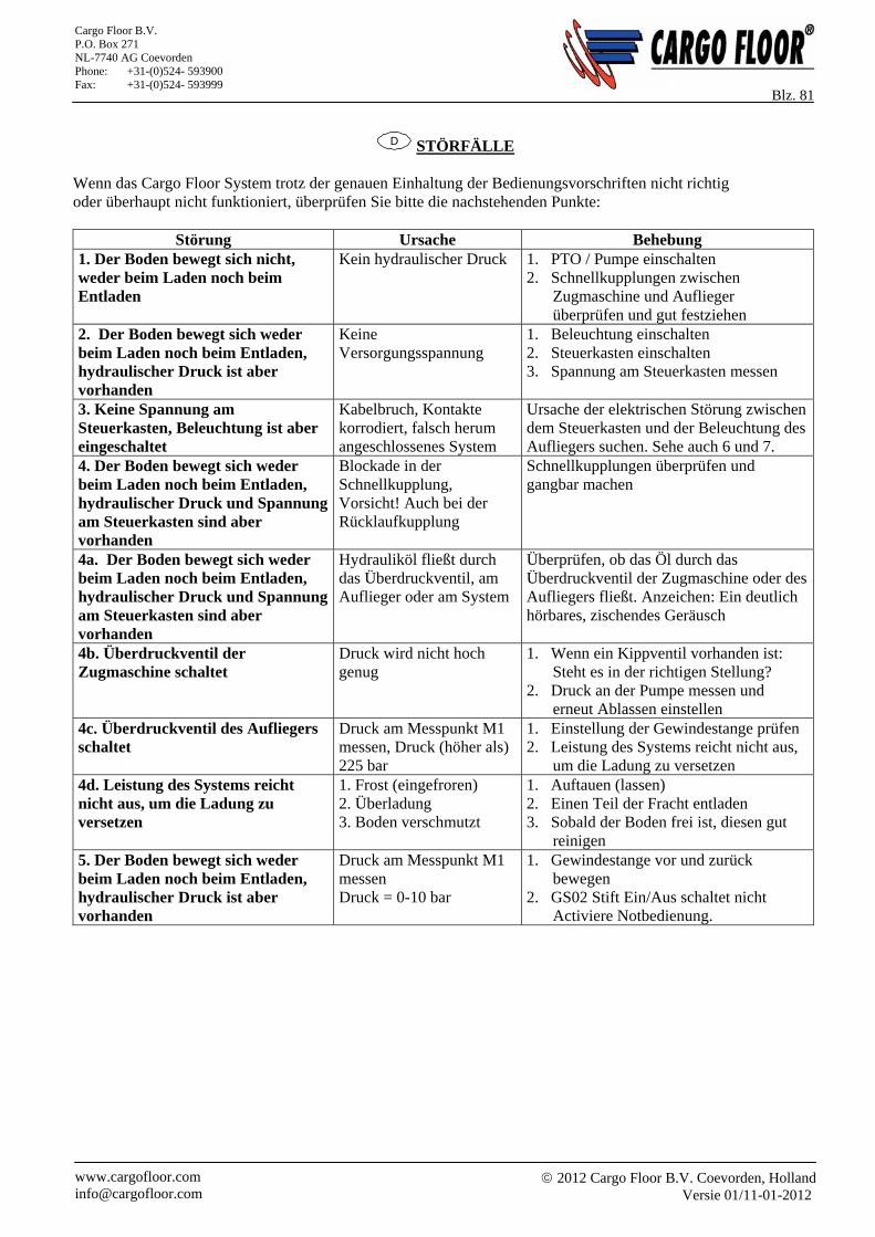
2012 Cargo Floor B.V. Coevorden, Holland
Versie 01/11-01-2012 www.cargofloor.com [email protected]
Cargo Floor B.V. P.O. Box 271 NL-7740 AG Coevorden Phone: +31-(0)524- 593900 Fax: +31-(0)524- 593999
Blz. 81
D STÖRFÄLLE Wenn das Cargo Floor System trotz der genauen Einhaltung der Bedienungsvorschriften nicht richtig oder überhaupt nicht funktioniert, überprüfen Sie bitte die nachstehenden Punkte:
Störung Ursache Behebung 1. Der Boden bewegt sich nicht, weder beim Laden noch beim Entladen
Kein hydraulischer Druck 1. PTO / Pumpe einschalten 2. Schnellkupplungen zwischen
Zugmaschine und Auflieger überprüfen und gut festziehen
2. Der Boden bewegt sich weder beim Laden noch beim Entladen, hydraulischer Druck ist aber vorhanden
Keine Versorgungsspannung
1. Beleuchtung einschalten 2. Steuerkasten einschalten 3. Spannung am Steuerkasten messen
3. Keine Spannung am Steuerkasten, Beleuchtung ist aber eingeschaltet
Kabelbruch, Kontakte korrodiert, falsch herum angeschlossenes System
Ursache der elektrischen Störung zwischen dem Steuerkasten und der Beleuchtung des Aufliegers suchen. Sehe auch 6 und 7.
4. Der Boden bewegt sich weder beim Laden noch beim Entladen, hydraulischer Druck und Spannung am Steuerkasten sind aber vorhanden
Blockade in der Schnellkupplung, Vorsicht! Auch bei der Rücklaufkupplung
Schnellkupplungen überprüfen und gangbar machen
4a. Der Boden bewegt sich weder beim Laden noch beim Entladen, hydraulischer Druck und Spannung am Steuerkasten sind aber vorhanden
Hydrauliköl fließt durch das Überdruckventil, am Auflieger oder am System
Überprüfen, ob das Öl durch das Überdruckventil der Zugmaschine oder des Aufliegers fließt. Anzeichen: Ein deutlich hörbares, zischendes Geräusch
4b. Überdruckventil der Zugmaschine schaltet
Druck wird nicht hoch genug
1. Wenn ein Kippventil vorhanden ist: Steht es in der richtigen Stellung?
2. Druck an der Pumpe messen und erneut Ablassen einstellen
4c. Überdruckventil des Aufliegers schaltet
Druck am Messpunkt M1 messen, Druck (höher als) 225 bar
1. Einstellung der Gewindestange prüfen 2. Leistung des Systems reicht nicht aus,
um die Ladung zu versetzen 4d. Leistung des Systems reicht nicht aus, um die Ladung zu versetzen
1. Frost (eingefroren) 2. Überladung 3. Boden verschmutzt
1. Auftauen (lassen) 2. Einen Teil der Fracht entladen 3. Sobald der Boden frei ist, diesen gut
reinigen 5. Der Boden bewegt sich weder beim Laden noch beim Entladen, hydraulischer Druck ist aber vorhanden
Druck am Messpunkt M1 messen Druck = 0-10 bar
1. Gewindestange vor und zurück bewegen
2. GS02 Stift Ein/Aus schaltet nicht Activiere Notbedienung.
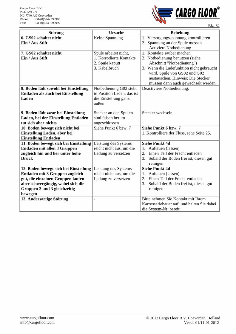
2012 Cargo Floor B.V. Coevorden, Holland
Versie 01/11-01-2012 www.cargofloor.com [email protected]
Cargo Floor B.V. P.O. Box 271 NL-7740 AG Coevorden Phone: +31-(0)524- 593900 Fax: +31-(0)524- 593999
Blz. 82 Störung Ursache Behebung
6. GS02 schaltet nicht Ein / Aus Stift
Keine Spannung 1. Versorgungsspannung kontrollieren 2. Spannung an der Spule messen
Activiere Notbedienung. 7. GS02 schaltet nicht Ein / Aus Stift
Spule arbeitet nicht, 1. Korrodierte Kontakte 2. Spule kaputt 3. Kabelbruch
1. Kontakte sauber machen 2. Notbedienung benutzen (siehe
Abschnitt "Notbedienung") 3. Wenn die Ladefunktion nicht gebraucht
wird, Spule von GS02 und G02 austauschen. Hinweis: Die Stecker müssen dann auch gewechselt werden
8. Boden lädt sowohl bei Einstellung Entladen als auch bei Einstellung Laden
Notbedienung G02 steht in Position Laden, das ist die Einstellung ganz außen
Deactiviere Notbedienung.
9. Boden lädt zwar bei Einstellung Laden, bei der Einstellung Entladen tut sich aber nichts
Stecker an den Spulen sind falsch herum angeschlossen
Stecker wechseln
10. Boden bewegt sich nicht bei Einstellung Laden, aber bei Einstellung Entladen
Siehe Punkt 6 bzw. 7 Siehe Punkt 6 bzw. 7 1. Kontrolliere der Fluss, sehe Seite 25.
11. Boden bewegt sich bei Einstellung Entladen mit allen 3 Gruppen zugleich hin und her unter hohe Druck
Leistung des Systems reicht nicht aus, um die Ladung zu versetzen
Siehe Punkt 4d 1. Auftauen (lassen) 2. Einen Teil der Fracht entladen 3. Sobald der Boden frei ist, diesen gut
reinigen 12. Boden bewegt sich bei Einstellung Entladen mit 3 Gruppen zugleich gut, die einzelnen Gruppen laufen aber schwergängig, wobei sich die Gruppen 2 und 3 gleichzeitig bewegen
Leistung des Systems reicht nicht aus, um die Ladung zu versetzen
Siehe Punkt 4d 1. Auftauen (lassen) 2. Einen Teil der Fracht entladen 3. Sobald der Boden frei ist, diesen gut
reinigen
13. Andersartige Störung - Bitte nehmen Sie Kontakt mit Ihrem Karrosseriebauer auf, und halten Sie dabei die System-Nr. bereit
2012 Cargo Floor B.V. Coevorden, Holland
Versie 01/11-01-2012 www.cargofloor.com [email protected]
Cargo Floor B.V. P.O. Box 271 NL-7740 AG Coevorden Phone: +31-(0)524- 593900 Fax: +31-(0)524- 593999
Blz. 83
NL GARANTIEBEPALINGEN
Garantie wordt alleen toegekend mits vooraf toestemming door Cargo Floor B.V. is verleend! Bij garantie aanvragen dient u altijd vooraf een garantieaanvraagformulier in te vullen en Cargo Floor B.V. toe te sturen. Het garantie aanvraagformulier kunt u eenvoudig via het internet vinden, ga hiervoor naar: www.cargofloor.com De garantievoorwaarden zoals verwoord in de laatstelijke tekst van de Metaalunie voorwaarden, gedeponeerd ter Griffie van de Rechtbank te Rotterdam, zijn onverkort van toepassing. Deze zijn op aanvraag beschikbaar. Een kort uittreksel volgt onderstaand; Op alle door ons geleverde materialen behorende bij het Cargo Floor-systeem geldt een garantieperiode van 12 maanden ingaande direct na de montage. In geval van storingen en/of fabricagefouten zijn wij slechts gehouden tot het kosteloos verstrekken van vervangende onderdelen, indien: - Het Cargo Floor systeem overeenkomstig onze inbouwvoorschriften door uw bouwer is ingebouwd. - Onze onderhouds- en bedieningsvoorschriften zijn nageleefd. - In geval van een storing, de carrosseriebouwer, of Cargo Floor hiervan omgaand in kennis werd gesteld Niet onder garantie vallen: - Storingen aan, of veroorzaakt door, niet door Cargo Floor B.V. geleverde apparatuur. - Storingen veroorzaakt door vervuiling en/of verkeerde olie.
- Storingen veroorzaakt door oververhitte olie, T. max. 70 °C.
- Storingen veroorzaakt door overbelading of onoordeelkundig gebruik. - Storingen veroorzaakt door reparaties, uitgevoerd door derden. - Filterelementen en slijtdelen. - Defecten aan elektrische delen, t.g.v. slechte aansluitingen en/of verkeerde elektrische spanningen - Gevolgschades
De garantie vervalt indien: - Het systeem wordt gebruikt voor doeleinden die niet door Cargo Floor zijn aanbevolen. - Het Cargo Floor systeem niet op de juiste wijze door uw carrosseriebouwer is ingebouwd, voor zover dit de
werking van het systeem negatief beïnvloedt.
2012 Cargo Floor B.V. Coevorden, Holland
Versie 01/11-01-2012 www.cargofloor.com [email protected]
Cargo Floor B.V. P.O. Box 271 NL-7740 AG Coevorden Phone: +31-(0)524- 593900 Fax: +31-(0)524- 593999
Blz. 84
GB GUARANTEE CONDITIONS
Guarantee shall only be given with the prior consent of Cargo Floor B.V.! With guarantee requests always fill in and send a guarantee request form to Cargo Floor B.V. beforehand. You can fill in a request for guarantee simply on our website: www.cargofloor.com The guarantee conditions, as specified in the most recent “Metaalunie” conditions, filed with the registrar of the District Court of Rotterdam, are applicable in unabbreviated form. On request available. A short extract of these conditions follows: A guarantee period of 12 months (starting directly after installation) applies for all Cargo Floor system materials supplied by us. In the case of malfunction and/or manufacturing faults we are only responsible for the costless supply of replacement parts, if: - The Cargo Floor system is installed by your trailer builder according to our installation procedures. - Our maintenance and control procedures have been followed. - In the case of a malfunction, the system builder, or Cargo Floor have been informed The following components are not covered by the guarantee: - Malfunction of equipment, or caused by equipment, which was not supplied by Cargo Floor. - Malfunction caused by the use of dirty oil, or oil of the wrong type.
- Malfunction caused by overheated oil, T. max. 70 °C. - Malfunction caused by overloading or injudicious use. - Malfunction caused by repair work, which is carried out by third parties. - Filter elements and components, which are subject to wear-and-tear. - Defects in electrical components due to incorrect connection and/or incorrect voltage levels.
- Resulting damages
The guarantee is void if: - The system is used for purposes, which have not been recommended by Cargo Floor. - The Cargo Floor system has not constructed correctly by your trailer builder, insofar as this has a negative
influence on the operation of the system.
2012 Cargo Floor B.V. Coevorden, Holland
Versie 01/11-01-2012 www.cargofloor.com [email protected]
Cargo Floor B.V. P.O. Box 271 NL-7740 AG Coevorden Phone: +31-(0)524- 593900 Fax: +31-(0)524- 593999
Blz. 85
D GARANTIEBESTIMMUNGEN Garantie wird nur bei vorheriger Zustimmung von Cargo Floor B.V. gewährt! Bei einem Garantieantrag sollen Sie immer vorab Cargo Floor B.V. ein Antragformular zuschicken. Ein Garantieantrag können Sie einfach bei unserem Website anmelden, gehe dafür zu: www.cargofloor.com Die Garantiebestimmungen, mit dem entsprechenden Wortlaut der aktuellen Version der „Metaalunie“ Bedingungen, wie diese bei der Geschäftsstelle des Landgerichts in Rotterdam deponiert worden sind, sind uneingeschränkt gültig. Auf Anfrage erhältlich. Nachstehend finden Sie einen kurzen Auszug aus diesen Bestimmungen: Auf alle von uns gelieferten Materialien, die zu dem Cargo Floor System gehören, leisten wir eine Garantie von 12 Monaten, deren Dauer unmittelbar nach der Montage beginnt. Bei Störungen und/oder Fabrikationsfehlern sind wir nur dann für die kostenlose Stellung von Ersatzteilen verpflichtet, wenn: - das Cargo Floor System gemäß unseren Einbauvorschriften durch Ihren Karosseriehersteller eingebaut wurde; - unsere Wartungs- und Bedienungsvorschriften eingehalten wurden; - im Fall einer Störung, der Installateur oder Cargo Floor diesbezüglich umgehend unterrichtet wurden. Nicht von der Garantie abgedeckt sind: - Störungen an oder verursacht durch nicht von Cargo Floor B.V. gelieferte(n) Anlagen und Geräten; - Störungen auf Grund von Verschmutzung und/oder falschem Öl;
- Störungen, die durch überhitztes Öl verursacht werden, T. max. 70 °C - Störungen, die durch Überladung oder unsachgemäßen Gebrauch verursacht wurden; - Störungen, die durch von Dritten vorgenommenen Reparaturen verursacht wurden; - Filterelemente und Verschleißteile; - Defekte an elektrischen Komponenten, infolge von schadhaften/falschen Anschlüssen und/oder falschen
elektrischen Spannungen;
- Folgeschaden. Die Garantie erlischt, wenn: - das System für andere als die von Cargo Floor empfohlenen Zwecke eingesetzt wird; - das Cargo Floor System von Ihrem Karosseriehersteller nicht richtig eingebaut wurde, dies insoweit, wie
dadurch die Funktionalität des Systems negativ beeinflusst wird.
2012 Cargo Floor B.V. Coevorden, Holland
Versie 01/11-01-2012 www.cargofloor.com [email protected]
Cargo Floor B.V. P.O. Box 271 NL-7740 AG Coevorden Phone: +31-(0)524- 593900 Fax: +31-(0)524- 593999
Blz. 86
NL Bijlagen
GB Enclosed
D Anlagen
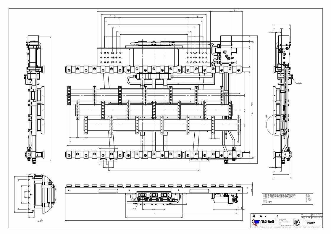
1,5 max.
=1090=
1351200
112 112 336
=2240±2=
A SCALE 2 : 5
=
=40
=
=120
=
=200 =
=240
40
25Nm.
A
119
8032
112
80
112
247
208,4
32
231
Q
V/CyclusQ
: 110 L/min.max.
: 15 L/min.min.
: 8,5 L
Max. working pressure in pressure pipeMax. working pressure in return pipe
: 225 bar: 10 bar
100Nm.
±2
149
70
80
2340
317
=750=
150 150
1100
1649
1282
38
1065
85
=
60
362,5
1500=
200
=
271
890
=990
=
=
1210
1290
=
1390=
259,5
=
=
=
=
60
==2295
2278±2
250
195
312,5
195
125
=900= 200
149
1690
80
1545 min. / 1745 max.
79
Page S1
CF500 SL-2 H80 21/112 E
E-mail : [email protected]
THIS DRAWING IS THE PROPERTY OF CARGO FLOOR b.v. AND MUST NOT BE COPIED OR REPRODUCED WITHOUT THEIR WRITTEN AUTHORITY
Cargo Floor B.V.P.O. Box 271NL-7740 AG CoevordenPhone : +31-524-593900Fax : +31-524-593999
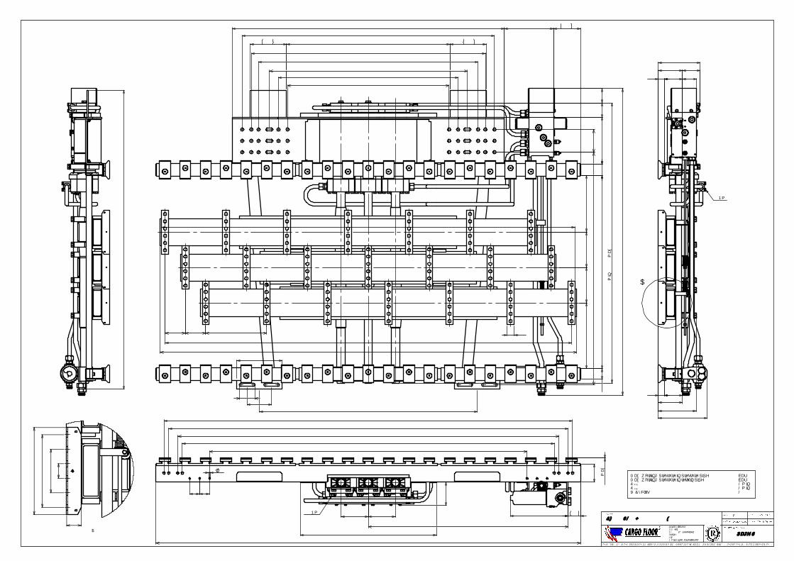
1,5 max.
=1090=
1351200
112 112 336
=2240±2=
min.
max.
: 15 L/min.: 8,5 L
QV/Cyclus
Q : 110 L/min.
Max. working pressure in pressure pipeMax. working pressure in return pipe
: 225 bar: 10 bar
100Nm.
=
2050=
=
=2100
=
2200=
=2250
70
=
55
1750
55
=
=
9
±2
100
2340
317
129
=750=
150 150
1100
E-mail : [email protected]
Page S2
CF500 SL-2 H100 21/112 ECargo Floor B.V.P.O. Box 271NL-7740 AG CoevordenPhone : +31-524-593900Fax : +31-524-593999
THIS DRAWING IS THE PROPERTY OF CARGO FLOOR b.v. AND MUST NOT BE COPIED OR REPRODUCED WITHOUT THEIR WRITTEN AUTHORITY
A (2 : 5)
==
40
=
= 120
=
=200=
=240
40
25Nm.
A
269208,4
99
32
231
100
132
100
132
32
79
1649
890= =
271
= =
=
990
1210
=
=
1290
1390
259,5
313,5
195
195
=
361,5
=
=
60
85
=
1065
=
125
1500
200
=
=2295
2278±2
60
250
38
1282
=900= 200
149
1690
80
1545 min. / 1745 max.
79
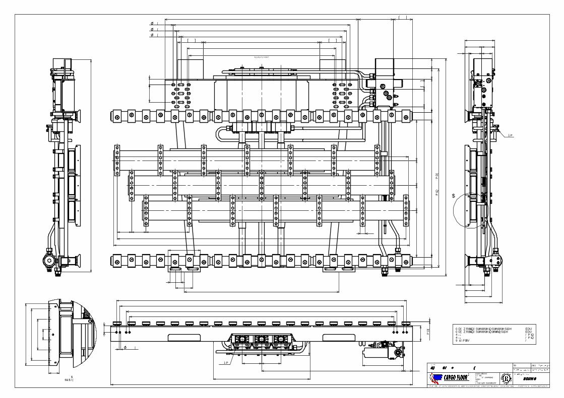
1351200
112 112 336
=2240±2=
=1155=
==1370
=1250=
1315= =
=1130=
17x45
17x25
17x34
1,5 max.
=750=
1649
E-mail : [email protected]
Page S3
CF500 SL-2 H120 21/112 ECargo Floor B.V.P.O. Box 271NL-7740 AG CoevordenPhone : +31-524-593900Fax : +31-524-593999
THIS DRAWING IS THE PROPERTY OF CARGO FLOOR b.v. AND MUST NOT BE COPIED OR REPRODUCED WITHOUT THEIR WRITTEN AUTHORITY
(REFERENTIE MAAT)
=
361,538
259,5
271
79
45
60
313,5
195
195
=
±22278
2295250
=
136
900
1065
136
60
=
1260
200
85
=1500
= 200
149
1690
min. / 1745 max.
80
1545
79
A SCALE 2 : 5
= =200
=
=
40=
=120
==240
40
25Nm.
A
100
289
208,4
32
99
231
152
132
12032
79
: 8,5 Lmin.
max.
: 15 L/min.Q
V/Cyclus
: 110 L/min.Q
Max. working pressure in pressure pipeMax. working pressure in return pipe
: 225 bar: 10 bar
100Nm.
=
=
2050
=
2100
2200
=
=
2250
=
120
=109
±2
=
2340
50
317
70
13(16x)
150150
1100
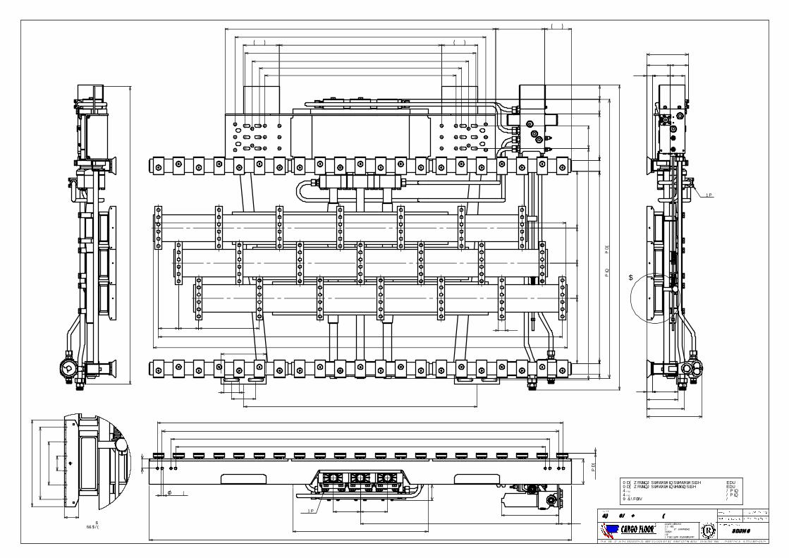
112 112 336
=2240±2=
1295
135
1,5 max.
=750=
25Nm.
A
307
208,4
7932
99
100
132
140
172
32
231
A SCALE 2 : 5
==
40
=
= 120
=
=200=
=240
40
38
271
259
=
60
195
60
195
==2295
2278±2
1500
=900=
= =
=
1060
1200
=
=
=
1280
1390
1065
=
=
250
314
85
125
200
1282
361
=
200
149
1690
80
1545
=
min. / 1745 max.
=1120
79
1649
: 8,5 Lmin.
max.
: 15 L/min.QV/Cyclus
Q : 110 L/min.
Max. working pressure in pressure pipeMax. working pressure in return pipe
: 225 bar: 10 bar
100Nm.
=2100
2200=
2250=
=
±2
=
140
89
2340
=
50
70
317
==2050
13(16x)
150 150
1100
E-mail : [email protected]
Page S4
CF500 SL-2 H140 21/112 ECargo Floor B.V.P.O. Box 271NL-7740 AG CoevordenPhone : +31-524-593900Fax : +31-524-593999
THIS DRAWING IS THE PROPERTY OF CARGO FLOOR b.v. AND MUST NOT BE COPIED OR REPRODUCED WITHOUT THEIR WRITTEN AUTHORITY
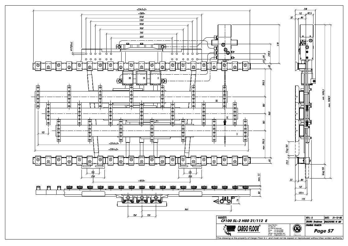
Certified companyISO 9001 - 2008
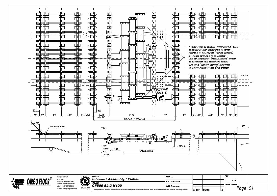
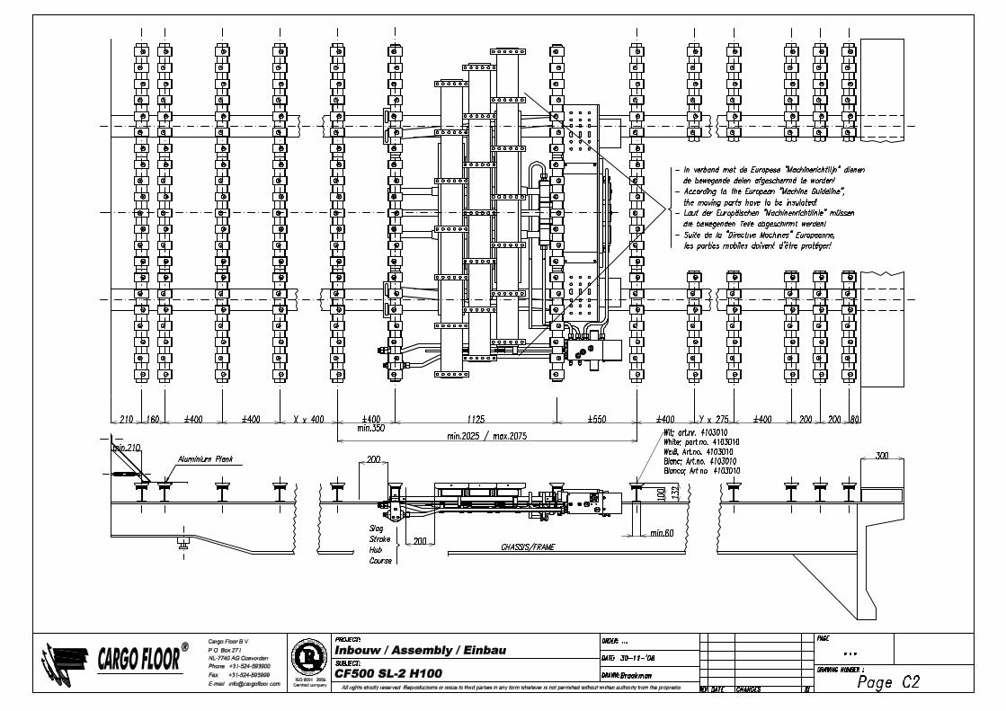
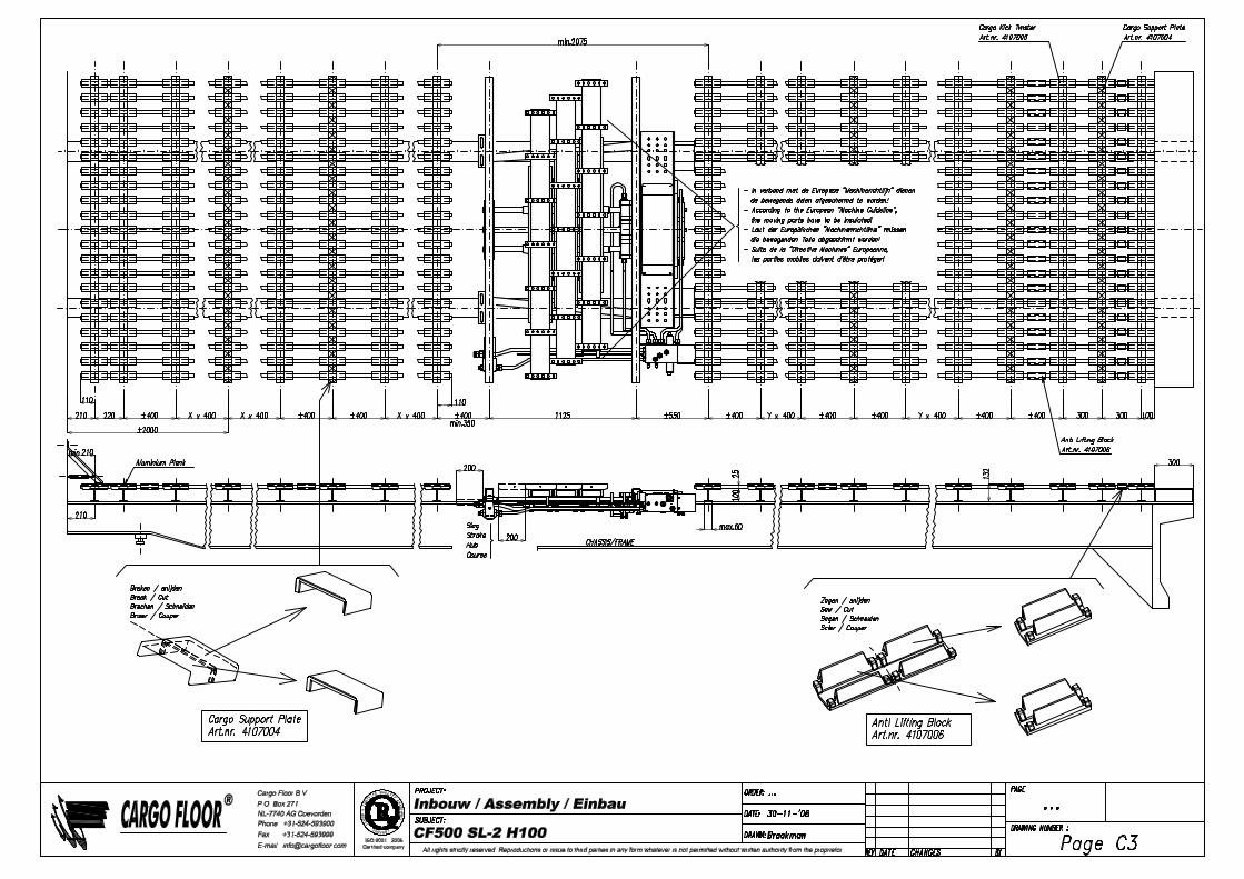
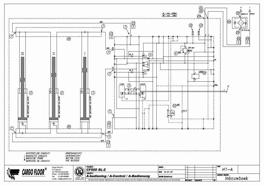
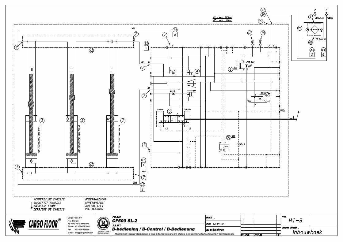
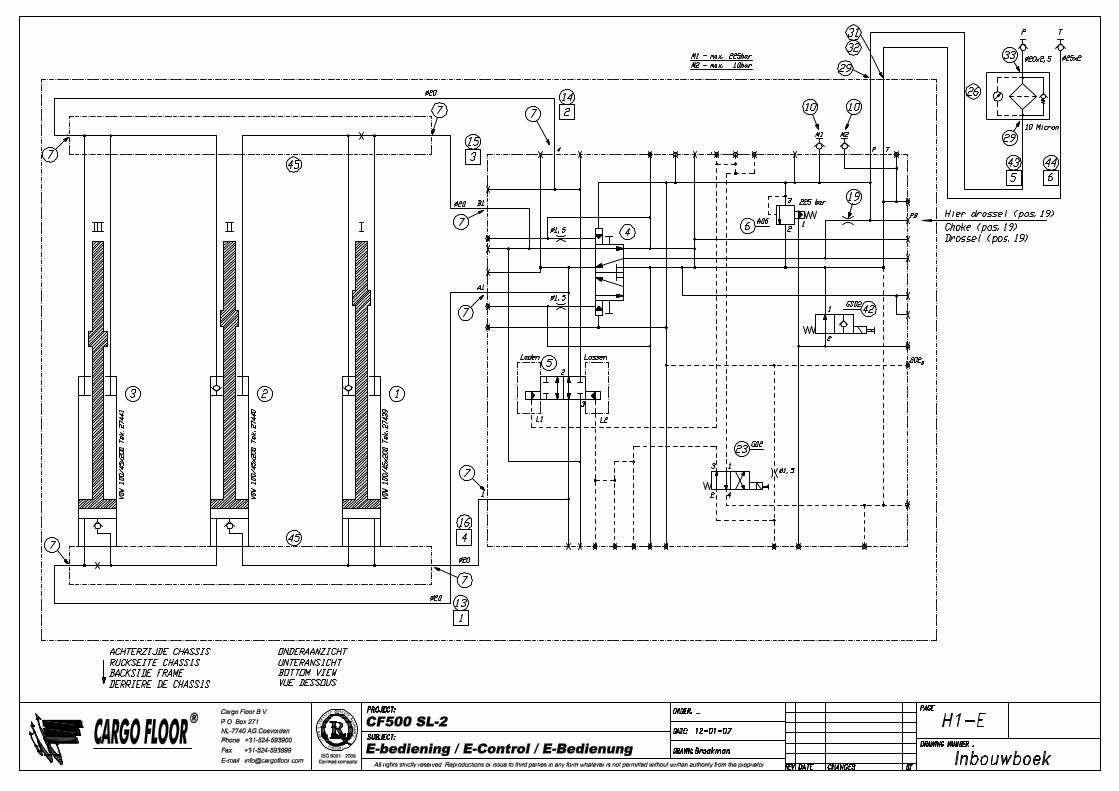

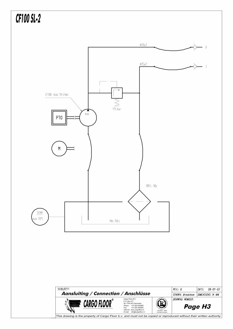
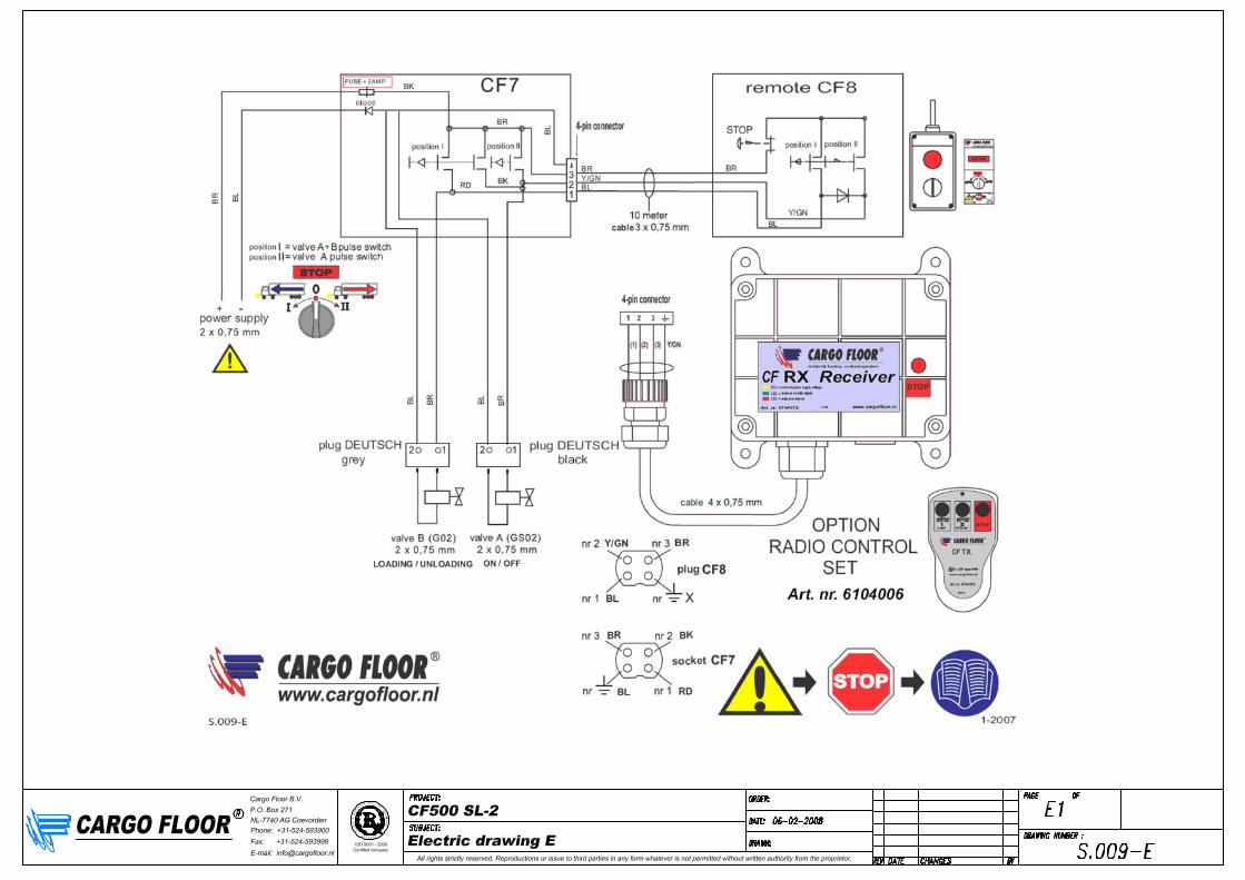

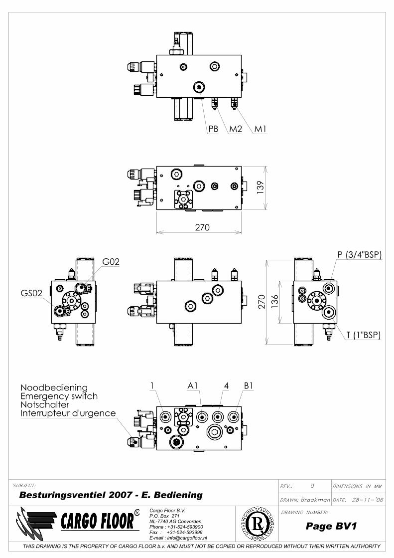
REV.:
Page BV1
Besturingsventiel 2007 - E. BedieningBraakman
DIMENSIONS IN MM0
28-11-'06
THIS DRAWING IS THE PROPERTY OF CARGO FLOOR b.v. AND MUST NOT BE COPIED OR REPRODUCED WITHOUT THEIR WRITTEN AUTHORITY
SUBJECT:
DRAWING NUMBER:
DRAWN: DATE:
Cargo Floor B.V.P.O. Box 271NL-7740 AG CoevordenPhone : +31-524-593900Fax : +31-524-593999E-mail : [email protected]
B14A11NoodbedieningEmergency switchNotschalterInterrupteur d'urgence
P (3/4"BSP)
T (1"BSP)
136
270
PB M2 M1
270
139
GS02
G02
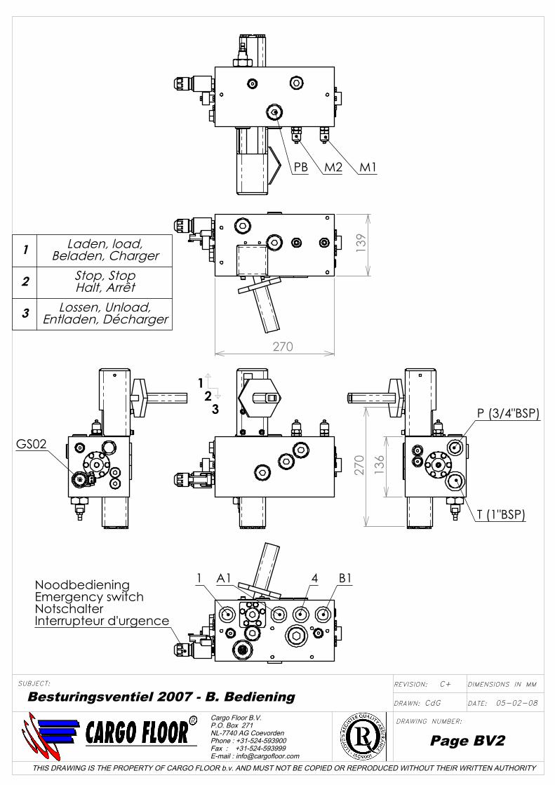
B14A11NoodbedieningEmergency switchNotschalterInterrupteur d'urgence
27013
9
PB M2 M1
GS02
136
270
P (3/4"BSP)
T (1"BSP)
1 2 3
1 Laden, load,Beladen, Charger
2 Stop, StopHalt, Arrêt
3 Lossen, Unload,Entladen, Décharger
THIS DRAWING IS THE PROPERTY OF CARGO FLOOR b.v. AND MUST NOT BE COPIED OR REPRODUCED WITHOUT THEIR WRITTEN AUTHORITY
SUBJECT:
DRAWING NUMBER:
DRAWN: DATE:
REVISION:
Page BV2
Besturingsventiel 2007 - B. Bediening CdG
DIMENSIONS IN MMC+
05-02-08
Cargo Floor B.V.P.O. Box 271NL-7740 AG CoevordenPhone : +31-524-593900Fax : +31-524-593999E-mail : [email protected]