Embed Size (px)
Citation preview

Page 1scanCONTROL 2900/2950BL
Assembly Instructions
scanCONTROL 2900/2950BL
1. WarningsConnect the power supply and the display-/output device according to the safety regulations for electrical equipment. The supply voltage must not exceed the specified limits.
> Risk of injury, damage to or destruction of the sensor
Avoid shocks and impacts to the sensor. Avoid constant exposure of the sensor to dust and splashes of water. Avoid exposure of sensor to aggressive materials (detergents, cooling emulsions).
> Damage to or destruction of the sensor
Read the detailed operation instructions before operating the sensor. These instructions are available online at www.micro-epsilon.com.
2. Notes on CE MarkingThe following apply to the scanCONTROL 2900/2950-xx/BL:
- EU Directive 2014/30/EU - EU Directive 2011/65/EU
The sensor is designed for use in industrial environments. The sensor satisfies the requirements if the guidelines in the operation instructions are maintained in installation and operation.
3. Proper Environment - Protection class: IP65 - Temperature range:
Operation: 0 ... +45 °C (+32 ... +113 °F), for free circulation of air Storage: -20 ... +70 °C (-4 ... +158 °F)
- Humidity: 5 - 95 % (non-condensing)
Page 2scanCONTROL 2900/2950BL
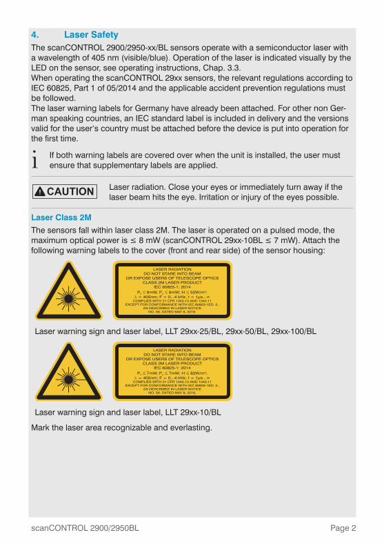
4. Laser SafetyThe scanCONTROL 2900/2950-xx/BL sensors operate with a semiconductor laser with a wavelength of 405 nm (visible/blue). Operation of the laser is indicated visually by the LED on the sensor, see operating instructions, Chap. 3.3. When operating the scanCONTROL 29xx sensors, the relevant regulations according to IEC 60825, Part 1 of 05/2014 and the applicable accident prevention regulations must be followed. The laser warning labels for Germany have already been attached. For other non Ger-man speaking countries, an IEC standard label is included in delivery and the versions valid for the user‘s country must be attached before the device is put into operation for the first time.
i If both warning labels are covered over when the unit is installed, the user must ensure that supplementary labels are applied.
Laser radiation. Close your eyes or immediately turn away if the laser beam hits the eye. Irritation or injury of the eyes possible.
Laser Class 2M
The sensors fall within laser class 2M. The laser is operated on a pulsed mode, the maximum optical power is ≤ 8 mW (scanCONTROL 29xx-10BL ≤ 7 mW). Attach the following warning labels to the cover (front and rear side) of the sensor housing:
Laser warning sign and laser label, LLT 29xx-25/BL, 29xx-50/BL, 29xx-100/BL
7 7 6
Laser warning sign and laser label, LLT 29xx-10/BL
Mark the laser area recognizable and everlasting.
Page 3scanCONTROL 2900/2950BL
scanCONTROL
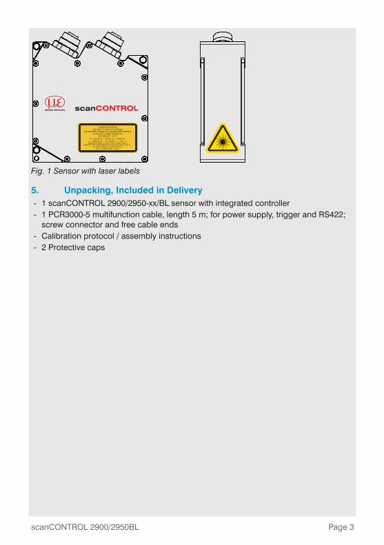
Fig. 1 Sensor with laser labels
5. Unpacking, Included in Delivery - 1 scanCONTROL 2900/2950-xx/BL sensor with integrated controller - 1 PCR3000-5 multifunction cable, length 5 m; for power supply, trigger and RS422;
screw connector and free cable ends - Calibration protocol / assembly instructions - 2 Protective caps
Page 4scanCONTROL 2900/2950BL
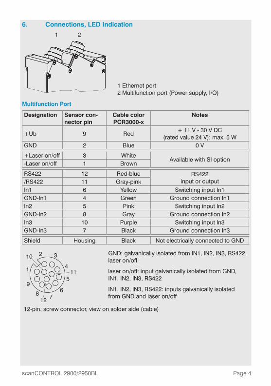
6. Connections, LED Indication
1 2
1 Ethernet port 2 Multifunction port (Power supply, I/O)
Multifunction Port
Designation Sensor con-nector pin
Cable color PCR3000-x
Notes
+Ub 9 Red+ 11 V - 30 V DC
(rated value 24 V); max. 5 WGND 2 Blue 0 V
+Laser on/off 3 WhiteAvailable with SI option
-Laser on/off 1 Brown
RS422 12 Red-blue RS422 input or output/RS422 11 Gray-pink
In1 6 Yellow Switching input In1GND-In1 4 Green Ground connection In1In2 5 Pink Switching input In2GND-In2 8 Gray Ground connection In2In3 10 Purple Switching input In3GND-In3 7 Black Ground connection In3
Shield Housing Black Not electrically connected to GND
2 3
4
5
678
9
1
10
11
12
GND: galvanically isolated from IN1, IN2, IN3, RS422, laser on/off
laser on/off: input galvanically isolated from GND, IN1, IN2, IN3, RS422
IN1, IN2, IN3, RS422: inputs galvanically isolated from GND and laser on/off
12-pin. screw connector, view on solder side (cable)
Page 5scanCONTROL 2900/2950BL
RS422, Synchronization
The RS422 connection (Pin 11 and 12 of the multifunction port) can be used in either of the following configurations:
- RS422 (half-duplex): Load user modes and sensor control, sensor control and transmission of measurement results (Modbus RTU or ASCII format)
- Synchronization/triggering: Synchronization or triggering using switching signals
Trigger, Encoder, Mode Switching
The switching inputs of the multifunction port can either be used for encoder input, trigger input or for load previously stored user modes. The signal levels are switchable for all switching inputs between LLL (low voltage, TTL logic) and HLL (high voltage, HTL logic):
- LLL level: Low 0 V … 0,8 V, high 2.4 V … 5 V, internal pull-up 10 kΩ connected to 5 V
- HLL level: Low 0 V … 3 V, high 11 V … 24 V (permitted to 30 V), internal pull-up 10 kΩ connected to 24 V
- Pulse duration: ≥ 5 µs
External Laser Switch-off, Optional
The external laser switch-off is implemented as a hardware solution and has a top prior-ity. The laser can be switched off, in addition, also by software.
This function is offered by sensors with the /BL-SI option.
Use a serial key switch in the control circuit to switch off the laser.
With standard sensors, connecting the supply voltage activates the laser light source in the sensor.
Wiring details are available in the operating instructions, Chap. 5.2.6.
Page 6scanCONTROL 2900/2950BL
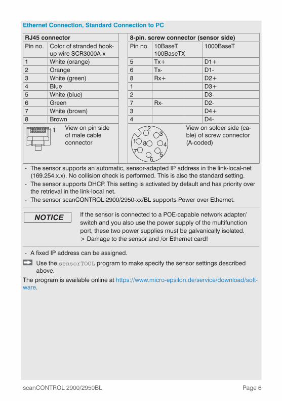
Ethernet Connection, Standard Connection to PC
RJ45 connector 8-pin. screw connector (sensor side)Pin no. Color of stranded hook-
up wire SCR3000A-xPin no. 10BaseT,
100BaseTX1000BaseT
1 White (orange) 5 Tx+ D1+2 Orange 6 Tx- D1-3 White (green) 8 Rx+ D2+4 Blue 1 D3+5 White (blue) 2 D3-6 Green 7 Rx- D2-7 White (brown) 3 D4+8 Brown 4 D4-
1 View on pin side of male cable connector
23
4
56
781
View on solder side (ca-ble) of screw connector (A-coded)
- The sensor supports an automatic, sensor-adapted IP address in the link-local-net (169.254.x.x). No collision check is performed. This is also the standard setting.
- The sensor supports DHCP. This setting is activated by default and has priority over the retrieval in the link-local net.
- The sensor scanCONTROL 2900/2950-xx/BL supports Power over Ethernet.
If the sensor is connected to a POE-capable network adapter/switch and you also use the power supply of the multifunction port, these two power supplies must be galvanically isolated. > Damage to the sensor and /or Ethernet card!
- A fixed IP address can be assigned.
Use the sensorTOOL program to make specify the sensor settings described above.
The program is available online at https://www.micro-epsilon.de/service/download/soft-ware.
Page 7scanCONTROL 2900/2950BL
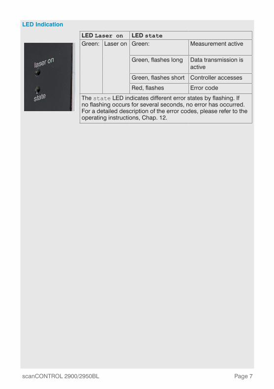
LED Indication
LED Laser on LED stateGreen: Laser on Green: Measurement active
Green, flashes long Data transmission is active
Green, flashes short Controller accesses
Red, flashes Error code
The state LED indicates different error states by flashing. If no flashing occurs for several seconds, no error has occurred. For a detailed description of the error codes, please refer to the operating instructions, Chap. 12.
Page 8scanCONTROL 2900/2950BL
7. System Requirements
scanCONTROL Configuration Tools
The following minimum system requirements are necessary:
- Windows 7, Windows 8 or 8.1, Windows 10 (each 32 bit and 64 bit) - 1-GHz or faster (32 bit and 64 bit) processor / 1 GB RAM - Screen resolution: 1024x768
scanCONTROL 3D-View
The following minimum system requirements are necessary:
- Windows 8 or 8.1 (64 bit), Windows 10 (64 bit) - 1-GHz or faster (64 bit) processor - 1 GB RAM - Screen resolution: 1024x768 - Graphic card / GPU with OpenGL 3.1 or higher
8. How to Access Profile DataProfile data of scanCONTROL can be accessed via:
- GigEVision and GenICam for digital cameras via Ethernet - SDK for fast application integration (C, C++, C# and others)
Please refer to the respective SDK documentation for further information on accessing the profile data.
9. Additional InformationPlease refer to
- the enclosed online documentation, - the “Status- and Error Messages“ and “Notes“ sections in the scanCONTROL Con-
figuration Tools operating instructions.
You will find details about the individual programs in the respective operating instruc-tions or in the operating instructions of this sensor, Chap. 6.2. You will find the operating instructions online at www.micro-epsilon.com.
Page 9scanCONTROL 2900/2950BL
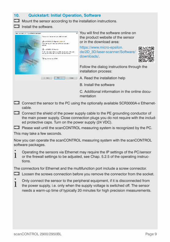
10. Quickstart: Initial Operation, Software Mount the sensor according to the installation instructions.
Install the software.
You will find the software online on the product website of the sensor or in the download area:
https://www.micro-epsilon.de/2D_3D/laser-scanner/Software/downloads/.
Follow the dialog instructions through the installation process:
A. Read the installation help
B. Install the software
C. Additional information in the online docu-mentation
Connect the sensor to the PC using the optionally available SCR3000A-x Ethernet-cable.
Connect the shield of the power supply cable to the PE grounding conductor of the main power supply. Close connection plugs you do not require with the includ-ed protective caps. Turn on the power supply (24 VDC).
Please wait until the scanCONTROL measuring system is recognized by the PC.
This may take a few seconds.
Now you can operate the scanCONTROL measuring system with the scanCONTROL software packages.
i Operating the sensors via Ethernet may require the IP settings of the PC/sensor or the firewall settings to be adjusted, see Chap. 5.2.5 of the operating instruc-tions.
The connectors for Ethernet and the multifunction port include a screw connector.
Loosen the screws connection before you remove the connector from the socket.
i Only connect the sensor to the peripheral equipment, if it is disconnected from the power supply, i.e. only when the supply voltage is switched off. The sensor needs a warm-up time of typically 20 minutes for high precision measurements.
Page 10scanCONTROL 2900/2950BL
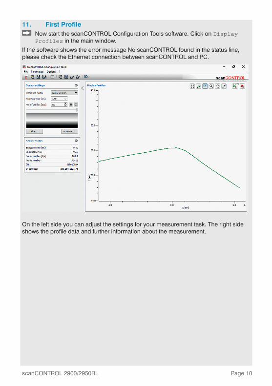
11. First Profile Now start the scanCONTROL Configuration Tools software. Click on Display Profiles in the main window.
If the software shows the error message No scanCONTROL found in the status line, please check the Ethernet connection between scanCONTROL and PC.
On the left side you can adjust the settings for your measurement task. The right side shows the profile data and further information about the measurement.

Page 11scanCONTROL 2900/2950BL

www.micro-epsilon.comMICRO-EPSILON Messtechnik GmbH & Co. KG
Koenigbacher Str. 15
94496 Ortenburg / Germany, Tel. +49 (0) 85 42/1 68-0
Your local contact: www.micro-epsilon.com/contact/worldwide/
X9771299.204-A032011HDR