Embed Size (px)
Citation preview

Gripping System FQE
Assembly Instructions
WWW.SCHMALZ.COM EN-US · 30.30.01.02497 · 01 · 03/21

Note
The Assembly instructions were originally written in German. Store in a safe place for future reference.Subject to technical changes without notice. No responsibility is taken for printing or other types of er-rors.
Published by
© J. Schmalz GmbH, 03/21
This document is protected by copyright. J. Schmalz GmbH retains the rights established thereby. Repro-duction of the contents, in full or in part, is only permitted within the limits of the legal provisions ofcopyright law. Any modifications to or abridgments of the document are prohibited without explicit writ-ten agreement from J. Schmalz GmbH.
Contact
J. Schmalz GmbH
Johannes-Schmalz-Str. 1
72293 Glatten, Germany
T: +49 7443 2403-0
www.schmalz.com
Contact information for Schmalz companies and trade partners worldwide can be found at:
www.schmalz.com/salesnetwork
2 / 48 EN-US · 30.30.01.02497 · 01 · 03/21

Contents
EN-US · 30.30.01.02497 · 01 · 03/21 3 / 48
Contents
1 Important Information ................................................................................................................................... 5
1.1 Warranty and Liability ........................................................................................................................ 5
1.2 The technical documentation is part of the product ........................................................................ 5
1.3 Note on Using this Document ............................................................................................................ 5
1.4 Warnings in This Document................................................................................................................ 6
1.5 Symbol.................................................................................................................................................. 6
1.6 Type Plate ............................................................................................................................................ 6
1.7 Other Applicable Documents ............................................................................................................. 6
2 Fundamental Safety Instructions................................................................................................................... 7
2.1 Intended Use........................................................................................................................................ 7
2.2 Non-Intended Use ............................................................................................................................... 7
2.3 Danger Zone ........................................................................................................................................ 7
2.4 Environmental and Operating Conditions......................................................................................... 8
2.5 Personnel Qualifications ..................................................................................................................... 8
2.6 Personal Protective Equipment .......................................................................................................... 9
2.7 Technical Condition............................................................................................................................. 9
2.8 Responsibility of the Integrator ......................................................................................................... 9
2.9 Country-Specific Regulations for the Operating Company .............................................................. 9
3 Product Description ...................................................................................................................................... 10
3.1 Description of the Gripper................................................................................................................ 10
3.2 FQE ... M............................................................................................................................................. 11
3.3 FQE ... Xb............................................................................................................................................ 12
3.4 FQE ... Xc ............................................................................................................................................ 13
4 Technical Data ............................................................................................................................................... 14
4.1 General Parameters........................................................................................................................... 14
4.2 Dimensions......................................................................................................................................... 16
4.3 Pneumatic Circuit Diagram (Version FQE ... Xc) .............................................................................. 17
4.4 Circuit Diagram for Valves (Version FQE ... Xc) ............................................................................... 18
4.5 Display Elements (Version FQE ... Xc) ............................................................................................... 18
5 Transport and Storage.................................................................................................................................. 20
5.1 Checking the Delivery ....................................................................................................................... 20
5.2 Reusing the Packaging...................................................................................................................... 20
6 Installation..................................................................................................................................................... 21
6.1 Installation Instructions..................................................................................................................... 21
6.2 Mechanical Attachment.................................................................................................................... 21
6.3 Electrical Connection......................................................................................................................... 24
6.4 Pneumatic connection....................................................................................................................... 26
7 Start of Operations ....................................................................................................................................... 28
7.1 Personnel Qualification..................................................................................................................... 28
7.2 Before Initial Start of Operations..................................................................................................... 28
8 Operation ...................................................................................................................................................... 31
8.1 Preparations....................................................................................................................................... 31

Contents
4 / 48 EN-US · 30.30.01.02497 · 01 · 03/21
9 Troubleshooting............................................................................................................................................ 32
9.1 Safety ................................................................................................................................................. 32
9.2 Faults, Causes, Solutions ................................................................................................................... 32
10 Maintenance.................................................................................................................................................. 34
10.1 Safety ................................................................................................................................................. 34
10.2 Maintenance Schedule...................................................................................................................... 34
10.3 Cleaning the Gripper......................................................................................................................... 35
10.4 Removing the Ejector Module.......................................................................................................... 36
10.5 Disassembling and Cleaning the Silencer Inserts............................................................................. 37
10.6 Removing the Sealing/Suction Plate ................................................................................................ 38
10.7 Replacing the Sealing Plate (Foam).................................................................................................. 38
10.8 Replacing Screw-in Suction Cups...................................................................................................... 39
10.9 Replacing Plug-in Suction Cups ........................................................................................................ 40
10.10 Accessories, Spare Parts and Wearing Parts..................................................................................... 41
11 Disposing of the Product.............................................................................................................................. 45
12 EC Conformity ............................................................................................................................................... 46

Important Information
EN-US · 30.30.01.02497 · 01 · 03/21 5 / 48
1 Important Information
1.1 Warranty and LiabilityJ. Schmalz GmbH, as a supplier and manufacturer of vacuum technology, takes no responsibility for thefunction of the product described below in a specific process.
The exact application parameters and the individual environment are decisive factors for selecting theright components. The specifications for our products are based on our current technical knowledge and experience, as wellas the available literature. We encourage you to test the products under the specific conditions that applyto your application purposes, and we would be glad to use our experience to assist you. The packaging material, the goods that are packaged, the fill level, porosity, surface condition, center ofgravity or the air content of the workpiece influence the entire handling process. Following functional testing, different suction cup sizes, additional suction cups, a higher suction rate ormodifications to the configuration may be necessary.
Therefore, J. Schmalz GmbH accepts no liability and excludes all legal claims for damages.
The products and the configurator are subject to technical changes or further development without no-tice.
We are not liable for any damage resulting from the use of non-original spare parts or accessories.
The exclusive use of original spare parts is a prerequisite for the proper functioning of the gripper and forthe validity of the warranty.
Wearing parts are not covered by the warranty.
1.2 The technical documentation is part of the product
1. For problem-free and safe operation, follow the instructions in the documents.
2. Keep the technical documentation in close proximity to the product. The documentation must be ac-cessible to personnel at all times.
3. Pass on the technical documentation to subsequent users.
ð Failure to follow the instructions in these Assembly instructions may result in life-threatening in-juries!
ð Schmalz is not liable for damage or malfunctions that result from failure to heed these instructions.
If you still have questions after reading the technical documentation, contact Schmalz Service at:
www.schmalz.com/services
1.3 Note on Using this DocumentJ. Schmalz GmbH is generally referred to as Schmalz in these Assembly instructions.
These Assembly instructions contain important notes and information about the different operatingphases of the product:
• Transport, storage, start of operations and decommissioning
• Safe operation, required maintenance, rectification of any faults
The Assembly instructions describe the product at the time of delivery by Schmalz.
Important Information
6 / 48 EN-US · 30.30.01.02497 · 01 · 03/21
1.4 Warnings in This DocumentWarnings warn against hazards that may occur when handling the product. The signal word indicates thelevel of danger.
Signal word Meaning
DANGER Indicates a high-risk hazard that will result in death or serious injury if notavoided.
WARNING Indicates a medium-risk hazard that could result in death or serious injury ifnot avoided.
CAUTION Indicates a low-risk hazard that could result in minor or moderate injury ifnot avoided.
NOTE Indicates a danger that leads to property damage.
1.5 Symbol
This symbol indicates useful and important information.
ü This symbol represents a prerequisite that must be met prior to an operational step.
4 This symbol represents an action to be performed.
ð This symbol represents the result of an action.
Actions that consist of more than one step are numbered:
1. First action to be performed.
2. Second action to be performed.
1.6 Type PlateThe type plate is permanently attached to the product and must always be clearly legible.
The type plate contains the following data:
• Product key
• Product service number
• Order number
• QR code – access to the Schmalz app
4 Please specify all the information above when ordering replacement parts, making warranty claimsor for any other inquiries.
1.7 Other Applicable DocumentsDepending on the configuration of the gripper FQE, the following operating instructions must also be ob-served:
• The operating instructions for the ejector nozzle SEP
• The operating instructions for the vacuum switch VSi

Fundamental Safety Instructions
EN-US · 30.30.01.02497 · 01 · 03/21 7 / 48
2 Fundamental Safety Instructions
2.1 Intended UseThe product described below is a universal gripper and is therefore not limited to a specific application.Due to its small size, low weight and energy efficiency, the gripper is suitable for applications on small ro-bots or even for human-robot collaboration applications.
The system must be operated only at the supply voltage specified for the components.
The load must only be vacuum-gripped in the position defined in advance or on initial set-up of the prod-uct.
Ensure that the load cannot slide or tip over during all phases of operation.
Use only the connections, mounting holes and attachment materials that have been provided.
The gripping system is built in accordance with the latest standards of technology and is delivered in asafe operating condition; however, hazards may arise during use.
The maximum lift capacity must not be exceeded (> See ch. Technical Data).
2.2 Non-Intended UseSchmalz accepts no liability for damage caused by the use of the gripper for purposes other than thosedescribed under Intended Use. Non-intended use includes the following:
• Lifting people or animals
• Storing loads while picked up
• Supporting the lifting process by applying external forces
• Applying suction to building components, equipment or supporting surfaces.
• Applying suction to bulk materials (e.g. granulates)
• Evacuation of objects that are in danger of imploding
• Use in potentially explosive atmospheres
• Freeing building components or immovable equipment
2.3 Danger ZonePersons in the danger zone of the gripper FQE may suffer life-threatening injuries.
Gripper operating modes
• Automatic operation on the industrial robot or gantry
• Collaborative operation on the lightweight robot (cobot)
For both operating modes, the system integrator must carry out a risk assessment of the entire system anddefine the danger zone precisely. In doing so, country-specific provisions and regulations must be ob-served.
Automatic operation on the industrial robot or gantry
• During automatic operation of the handling system, no persons or animals may be present in thedanger zone.
• In other operating modes, ensure that no unauthorized persons or animals are present in the dan-ger zone.
• Ensure that collisions with the surrounding environment and objects do not occur to prevent theload from breaking off.
During automatic operation of the handling system, the danger zone must be secured to prevent accessby persons (protective barrier or sensor system).
The danger zone of the gripper FQE includes the following areas:
• The area directly below the gripper and load.

Fundamental Safety Instructions
8 / 48 EN-US · 30.30.01.02497 · 01 · 03/21
• The area immediately surrounding the gripper and load.
• The working area of the automatic handling system.
2.4 Environmental and Operating ConditionsThe gripping system must not be operated under the following conditions:
• In potentially explosive atmospheres
• Use in an environment with acidic or alkaline media
CAUTIONDangerous gases, vapors or dusts are sucked in and dispersed by the vacuum gen-erator.
Difficulty breathing.
4 Before commencing work, ensure that the ambient air does not contain any hazardoussubstances.
4 Make sure that there are no hazardous substances on the load that can be sucked in.
4 If the ambient air is dusty, use a dust filter (particle size max. 5 µm).
CAUTIONBlockage of the vacuum system from sucking in liquids
Risk of injury from falling load!
4 Do not pick up liquids or bulk materials.
4 Observe the vacuum display.
4 If the suction of liquids cannot be avoided, use a water separator (contact Schmalz ser-vice).
The gripping system must be operated only under the following conditions:
• The environment must be free from humidity, moisture, dirt, dust, oil or other climatic conditionsthat may reduce friction levels.
• The gripping system must be sufficiently dimensioned for the loads to be lifted.
4 If in doubt, consult Schmalz before the start of operations.
2.5 Personnel QualificationsUnqualified personnel cannot recognize dangers and are therefore exposed to higher risks!
The operating company must ensure the following points:
• The personnel must be commissioned for the activities described in these instructions.
• The staff must be at least 18 years of age and physically and mentally capable.
• The product must be operated only by persons who have undergone appropriate training.
• Personnel must receive regular safety briefings (frequency as per country-specific regulations).
• Work on electrical equipment must be carried out only by qualified electrical specialists.
• Installation, maintenance, and repairs must be carried out only by specialists from J. Schmalz GmbHor by persons who can prove that they have undergone appropriate training at Schmalz.
The following target groups are addressed in these instructions:
• Mechanical and electrical specialists who are responsible for installing, troubleshooting and main-taining the product.

Fundamental Safety Instructions
EN-US · 30.30.01.02497 · 01 · 03/21 9 / 48
The operator of the system must comply with country-specific regulations regarding the age, ability andtraining of the personnel.
Valid for Germany:
A qualified employee is defined as an employee who has received technical training and has the knowl-edge and experience – including knowledge of applicable regulations – necessary to enable him or her torecognize possible dangers and implement the appropriate safety measures while performing tasks. Qual-ified personnel must observe the pertinent industry-specific rules and regulations.
2.6 Personal Protective EquipmentTo avoid injury, always use appropriate protective equipment that is suitable for the situation. The protec-tive equipment must meet the following standards:
• Protective work shoes in safety class S1 or higher
• Sturdy work gloves in safety category 2133 or higher
• Industrial helmet
• Ear protection class L or higher
• Eye protection class F
• Hair net
• Closely fitting clothing
2.7 Technical ConditionIf the product is operated while in a defective state, safety and function will be impaired.
• Only operate the gripper when in perfect working order as originally delivered.
• Follow the maintenance schedule.
• Use only original spare parts from Schmalz.
• If the operating behavior changes, check the gripper for faults. Rectify faults immediately!
• Do not independently modify or alter the gripper.
• Safety features must not be disabled under any circumstances.
Schmalz assumes no liability for consequences of modifications over which it has no control.
2.8 Responsibility of the IntegratorThe integrator is obligated to perform a risk assessment for the environmental conditions at the installa-tion location.
The integrator is also responsible for third parties in the working area of the gripper. The operating com-pany must ensure that they have the appropriate qualifications and skills.
• Ensure that regular breaks are taken.
• Ensure that the gripper cannot be started up by unauthorized persons.
• During maintenance or repair work, ensure that the gripper cannot be operated.
• Clearly define the responsibilities for the various activities performed with the gripper.
• Ensure that these responsibilities are observed.
• When handling unfamiliar loads, carry out tests where necessary to ensure safe operation:
– The load is sufficiently rigid that it cannot be damaged during handling.
2.9 Country-Specific Regulations for the Operating Company
1. Observe the country-specific regulations regarding accident prevention, safety testing and environ-mental protection.
2. The gripper is to be used in combination with an automated handling system (gantry/robot). Ensurethat the appropriate country-specific regulations and safety regulations are adhered to.
Product Description
10 / 48 EN-US · 30.30.01.02497 · 01 · 03/21
3 Product Description
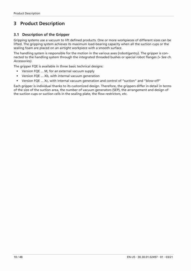
3.1 Description of the GripperGripping systems use a vacuum to lift defined products. One or more workpieces of different sizes can belifted. The gripping system achieves its maximum load-bearing capacity when all the suction cups or thesealing foam are placed on an airtight workpiece with a smooth surface.
The handling system is responsible for the motion in the various axes (robot/gantry). The gripper is con-nected to the handling system through the integrated threaded bushes or special robot flanges (> See ch.Accessories).
The gripper FQE is available in three basic technical designs:
• Version FQE ... M, for an external vacuum supply
• Version FQE ... Xb, with internal vacuum generation
• Version FQE ... Xc, with internal vacuum generation and control of “suction” and “blow-off”
Each gripper is individual thanks to its customized design. Therefore, the grippers differ in detail in termsof the size of the suction area, the number of vacuum generators (SEP), the arrangement and design ofthe suction cups or suction cells in the sealing plate, the flow restrictors, etc.
Product Description
EN-US · 30.30.01.02497 · 01 · 03/21 11 / 48
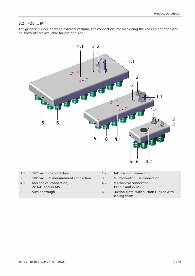
3.2 FQE ... MThe gripper is supplied by an external vacuum. The connections for measuring the vacuum and for exter-nal blow-off are available for optional use.
23
2
3
1.2
1.1
1.1
32
4.2
4.1
4.1
6
6
6
5
5
5
1.1 1/2" vacuum connection 1.2 1/4" vacuum connection
2 1/8" vacuum measurement connection 3 M5 blow-off pulse connection
4.1 Mechanical connection, 2x 1/4" and 4x M5
4.2 Mechanical connection, 1x 1/8" and 2x M5
5 Suction trough 6 Suction plate, with suction cups or withsealing foam

Product Description
12 / 48 EN-US · 30.30.01.02497 · 01 · 03/21
3.3 FQE ... XbDepending on the configuration, the gripper is equipped with one to three vacuum generators (SEP noz-zles). The connections for measuring the vacuum and for an external blow-off pulse are available for op-tional use.
4.1 2
1.1
3
2
1.13
6
6 4.1
62
4.2
3
1.2
5
5
5
1.1 1/4" compressed air connection 1.2 1/8" compressed air connection
2 1/8" vacuum measurement connection 3 M5 blow-off pulse connection
4.1 Mechanical connection, 2x 1/4" and 4x M5
4.2 Mechanical connection, 1x 1/8" and 2x M5
5 Suction trough 6 Suction plate, with suction cups or withsealing foam

Product Description
EN-US · 30.30.01.02497 · 01 · 03/21 13 / 48
3.4 FQE ... XcDepending on the configuration, the gripper is equipped with one to three vacuum generators (SEP noz-zles). The connections for measuring the vacuum and for an external blow-off pulse are available for op-tional use. “Suction” and “blow-off” can be controlled via the integrated valves.
4.1 2 1.1 7
3
2
2
71.1
3
6
6 4.1
7 1.2
3
4.2 6
5
5
5
1.1 1/4" compressed air connection 1.2 1/8" compressed air connection
2 1/8" vacuum measurement connection 3 M5 blow-off pulse connection
4.1 Mechanical connection, 2x 1/4" and 4x M5
4.2 Mechanical connection, 1x 1/8" and 2x M5
5 Suction trough 6 Suction plate, with suction cups or withsealing foam
7 M12-5 electrical connection

Technical Data
14 / 48 EN-US · 30.30.01.02497 · 01 · 03/21
4 Technical Data
4.1 General Parameters
Parameter Gripper type Unit
FQE ... M FQE ... Xb FQE ... Xc
Number of suction points Based on the configuration – see order confirmation
Operating pressure 3.0 – 6.0 bar
Maximum degree of evacua-tion (at opt. input pressure)
90*** 670(gripper size of 120x60 mm, 2 vacuum mod-
ules)610
(gripper size of 220x80 and 300x130 mm,2 or 3 vacuum modules)
mbar
Optimal input pressure –– 5.0 bar
Compressed air consumption*
–– 45 to 250 (depending on the number andsize of the SEP nozzles)
l/min
Max. suction rate –– 50 to 380 (depending on the number andsize of the SEP nozzles; see the order confir-
mation)
l/min
Permissible lift capacity ** 70 (gripper size of 120x60 mm)
160 (gripper size of 220x80 mm)
350 (gripper size of 300x130 mm)
N
Sound level at full coverage –– 64.1 (gripper size of 120x60 mm)
62.7 (gripper size of 220x80 mm)
64.6 (gripper size of 300x130 mm)
dB(A)
Operating voltage 24 V DC
Permitted temperaturerange
5 to +60 (withsealing foam)
-20 to +60(with suction
cups)
5 to +50 ° C
Foam/suction cup grid Based on the configuration – see order confirmation
Weight Based on the configuration – see order confirmation
* Compressed air provided by the customer: Dry and filtered air in accordance with ISO 8573-1:2010 [7:4:4]** Depending on the suction element and vacuum, the lift capacity cannot be reached or exceeded!*** Dependent on the vacuum generator but not above 90%

Technical Data
EN-US · 30.30.01.02497 · 01 · 03/21 15 / 48
Tool Center Point (TCP) and Center of Gravity (COG)
X
Z
Y
X
The information provided here is for an FQE Xc gripper with a flange for UR.

Technical Data
16 / 48 EN-US · 30.30.01.02497 · 01 · 03/21
4.2 Dimensions
L L2 B B2 H H1* H2 G1 G2 Dmk W X1 X2
FQE 120x60,sealing foam
120 120.1 60 60 55 75.7 10 1/8" M5 — — — 25
FQE 120x60,screw-in suc-tion cup
120 120.1 60 60 76.3 97 31.3 1/8" M5 — — — 25
FQE 120x60,plug-in suc-tion cup
120 120.1 60 60 69.3 90 24.3 1/8" M5 — — — 25
FQE 220x80,sealing foam
220 220.5 80 80.5 70 94 10 1/4" M5 55 27.5° 58 —

Technical Data
EN-US · 30.30.01.02497 · 01 · 03/21 17 / 48
FQE 220x80,screw-in suc-tion cup
220 220.5 80 80.5 91.3 115.3 31.3 1/4" M5 55 27.5° 58 —
FQE 220x80,plug-in suc-tion cup
220 220.5 80 80.5 84.3 108.3 24.3 1/4" M5 55 27.5° 58 —
FQE 300x130,sealing foam
300 220.5 130 80.5 70 94 10 1/4" M5 55 27.5° 58 —
FQE 300x130,screw-in suc-tion cup
300 220.5 130 80.5 91.3 115.3 31.3 1/4" M5 55 27.5° 58 —
FQE 300x130,plug-in suc-tion cup
300 220.5 130 80.5 84.3 108.3 24.3 1/4" M5 55 27.5° 58 —
* H1 is provided as an example and varies based on the configuration
4.3 Pneumatic Circuit Diagram (Version FQE ... Xc)
Control valve: suctionON/OFF
Control valve:blow off ON/OFF
Integrated vacuum generator(example)
Flow restrictor (SW)
Flowing compressed airpressure (optimum: 5 bar)

Technical Data
18 / 48 EN-US · 30.30.01.02497 · 01 · 03/21
4.4 Circuit Diagram for Valves (Version FQE ... Xc)
Suck Set down Idle position
Valve switchingstate: “Suck”
Valve switchingstate: “Blow off”
24V
24V
0
0
t
t
4.5 Display Elements (Version FQE ... Xc)With the gripper version FQE ... Xc, the “suction” and “blow-off” process states are each assigned an LED.
21

Technical Data
EN-US · 30.30.01.02497 · 01 · 03/21 19 / 48
Item Meaning State Description
1 Suction LED Lit up “Suction” OFF
OFF “Suction” ON (trans-port workpiece)
2 Blow-off LED Lit up “Blow-off” ON (depositworkpiece)
OFF “Blow-off” OFF
Transport and Storage
20 / 48 EN-US · 30.30.01.02497 · 01 · 03/21
5 Transport and Storage
5.1 Checking the DeliveryThe scope of delivery can be found in the order confirmation. The weights and dimensions are listed inthe delivery notes.
1. Compare the entire delivery with the supplied delivery notes to make sure nothing is missing.
2. Damage caused by defective packaging or occurring in transit must be reported immediately to thecarrier and J. Schmalz GmbH.
5.2 Reusing the PackagingThe product is delivered in cardboard packaging. The packaging should be reused to safely transport theproduct at a later stage.
Keep the packaging for future transport or storage.
Installation
EN-US · 30.30.01.02497 · 01 · 03/21 21 / 48
6 Installation
6.1 Installation Instructions
CAUTIONImproper installation or maintenance
Personal injury or damage to property
4 Prior to installation and before maintenance work, the product must be disconnectedfrom the power supply, depressurized (vented to the atmosphere) and secured againstunauthorized restart.
The gripper FQE may be installed in any position.
The grippers FQE can be mechanically connected as follows:
• Via the mounting holes in the housing (> See ch. Dimensions)
• Via the robot-specific connection sets (ROB-SET) that can be chosen during configuration
• Via various accessory parts such as a connecting plate, spring plunger, ball joint, Flexolink, etc.(> Seech. Accessories)
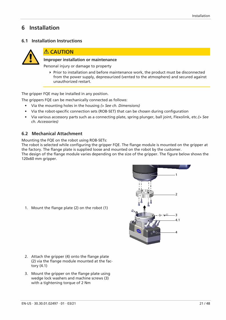
6.2 Mechanical AttachmentMounting the FQE on the robot using ROB-SETs:The robot is selected while configuring the gripper FQE. The flange module is mounted on the gripper atthe factory. The flange plate is supplied loose and mounted on the robot by the customer.The design of the flange module varies depending on the size of the gripper. The figure below shows the120x60 mm gripper.
1. Mount the flange plate (2) on the robot (1)
1
2
3
4
4.1
2. Attach the gripper (4) onto the flange plate(2) via the flange module mounted at the fac-tory (4.1)
3. Mount the gripper on the flange plate usingwedge lock washers and machine screws (3)with a tightening torque of 2 Nm

Installation
22 / 48 EN-US · 30.30.01.02497 · 01 · 03/21
Mounting the FQE directly on the mounting holes on the gripper:It is connected to the upper part of the housing using 1x 1/8" and 2x M5 (gripper size of 120x60 mm) or2x 1/4" and 4x M5 (gripper sizes of 220x80 mm and 300x130 mm) (> See ch. Dimensions).
Mounting the FQE on the mounting holes on the gripper using accessory parts such as connecting platesand spring plungers (> See ch. Accessories):The components for this type of connection are available as accessories for the respective gripper sizes.
• Connecting plates can be used to mechanically connect two to four grippers.
• Depending on the version, the connection elements have a connection thread of 1/8", 1/4" and 1/2"that allows them to be adapted to the Schmalz spring plunger.
• The connection and adapter plates are supplied with the screws required for mounting.
• The customer is responsible for choosing the appropriately sized connection (application, trans-ported load).
The spring plungers are to be positioned as far out as possible on the block-mounted grippers.An example for mounting 220x80 mm grippers on blocks is provided below.
1
2 3
1 Adapter plate (220x80 and 300x130 gripper sizes only)
2 Spring plunger
3 Connecting plate
Installation
EN-US · 30.30.01.02497 · 01 · 03/21 23 / 48
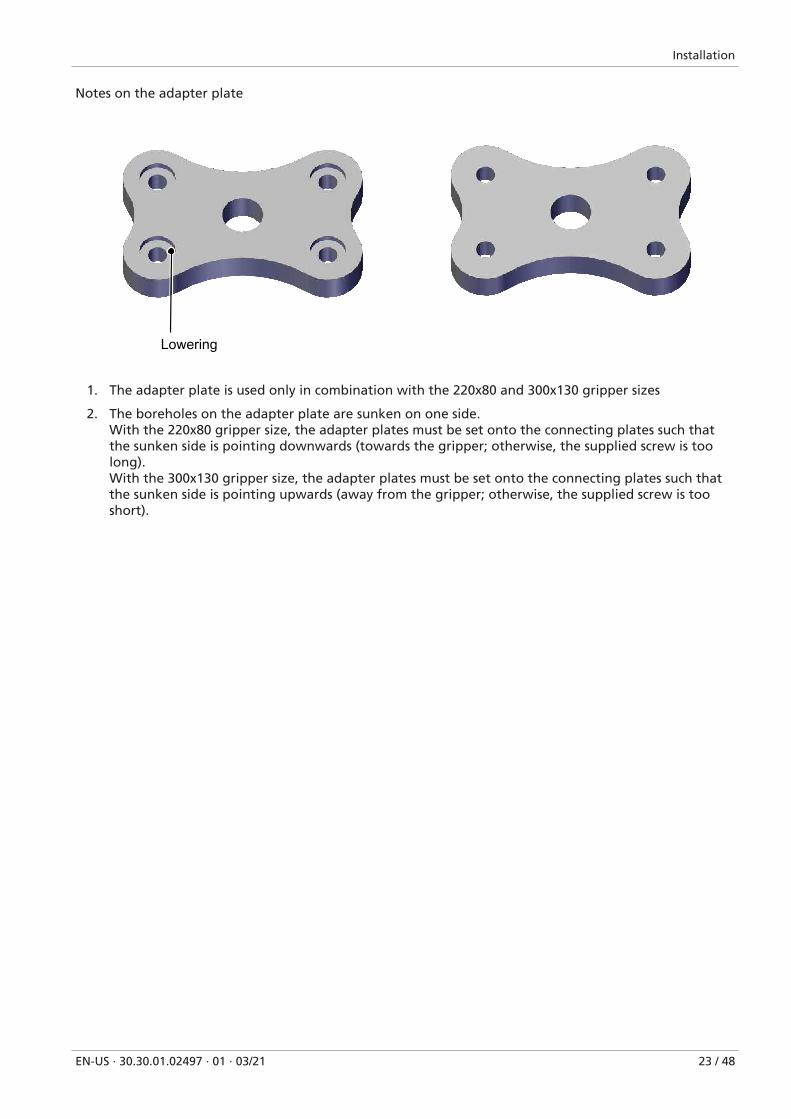
Notes on the adapter plate
Lowering
1. The adapter plate is used only in combination with the 220x80 and 300x130 gripper sizes
2. The boreholes on the adapter plate are sunken on one side.With the 220x80 gripper size, the adapter plates must be set onto the connecting plates such thatthe sunken side is pointing downwards (towards the gripper; otherwise, the supplied screw is toolong).With the 300x130 gripper size, the adapter plates must be set onto the connecting plates such thatthe sunken side is pointing upwards (away from the gripper; otherwise, the supplied screw is tooshort).

Installation
24 / 48 EN-US · 30.30.01.02497 · 01 · 03/21
6.3 Electrical Connection
DANGERElectric shock from touching live components
Serious injury or death!
4 Make sure that the electrical components are not live before installation, maintenanceand troubleshooting.
4 Switch off the mains switch and secure against unauthorized restart.
The gripper types FQE ... M and FQE ... Xb do not have electrical connections. With the gripper type FQE ... Xc, the integrated valves are activated via an M12-5 plug.
1
1
1
1 M12-5 electrical connection

Installation
EN-US · 30.30.01.02497 · 01 · 03/21 25 / 48
PNP version:
M12 connector Pin Litz wirecolor
Function
1 Brown Not used
2 White Blow-off valve “On”
3 Blue Ground
4 Black Suction valve “Off”
5 Gray Not used
NPN version:
M12 connector Pin Litz wirecolor
Function
1 Brown 24 V
2 White Blow-off valve “On”
3 Blue Not used
4 Black Suction valve “Off”
5 Gray Not used

Installation
26 / 48 EN-US · 30.30.01.02497 · 01 · 03/21
6.4 Pneumatic connection
1. Shorten the hoses and pipelines as much as possible.
2. Keep hose lines free of bends and crimps.
3. Lay hose lines in such a way that they do not rub.
Ensure that the hose lines have the appropriate dimensions.
CAUTIONCompressed air or vacuum in direct contact with the eye
Severe eye injury
4 Wear eye protection
4 Do not look into compressed air openings
4 Do not look into the silencer air stream
4 Do not look into vacuum openings, e.g. suction cups
The gripper type FQE ... M is supplied with an external vacuum. The gripper types FQE ... X come with in-tegrated vacuum generators (SEP nozzles).
The vacuum can be monitored on connection 2 (e.g. using a vacuum switch (> See ch. Accessories)).
To ensure that the workpiece is deposited quickly, an external blow-off pulse can be provided via connec-tion 3. In the case of the gripper FQE ... Xc, a blow-off pulse can be provided via the control.

Installation
EN-US · 30.30.01.02497 · 01 · 03/21 27 / 48
1.32
2 1.3
1.4
2 3
3
3
3
2 1.1
1.1
2
3
1.23
2
1.1 1/2" vacuum connection 1.2 1/4" vacuum connection
1.3 1/4" compressed air connection 1.4 1/8" compressed air connection
2 1/8" vacuum measurement connection 3 M5" blow-off pulse connection

Start of Operations
28 / 48 EN-US · 30.30.01.02497 · 01 · 03/21
7 Start of Operations
7.1 Personnel QualificationUnqualified personnel cannot recognize dangers and are therefore exposed to higher risks!
1. Only instruct qualified personnel to perform the tasks described in these operating instructions.
2. The product may only be operated by persons who have undergone appropriate training.
3. Electrical work and installations may only be carried out by qualified electrical specialists.
4. Assembly and maintenance work must only be carried out by qualified personnel.
7.2 Before Initial Start of OperationsBefore the initial start of operations following the installation, repair, servicing or maintenance work, youmust check the following:
• All mechanical connectors are properly attached and secured.
• All screws and nuts are tightened to specified torques.
• All components are installed.
• The safety distances have been maintained.
• The electrical cable and supply hoses are properly routed.
• The EMERGENCY STOP switch for the overall system is working.
• The type plate is clearly legible.
DANGERElectric shock from touching live components
Serious injury or death!
4 Make sure that the electrical components are not live before installation, maintenanceand troubleshooting.
4 Switch off the mains switch and secure against unauthorized restart.
CAUTIONNoise pollution due to incorrect installation of the pressure and vacuum connec-tions
Hearing damage
4 Correct installation.
4 Wear ear protectors.
CAUTIONVacuum close to the eye
Severe eye injury!
4 Wear eye protection.
4 Do not look into vacuum openings, e.g. suction cups.
Start of Operations
EN-US · 30.30.01.02497 · 01 · 03/21 29 / 48
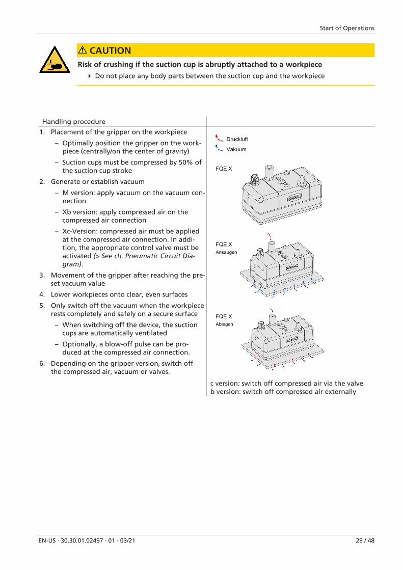
CAUTIONRisk of crushing if the suction cup is abruptly attached to a workpiece
4 Do not place any body parts between the suction cup and the workpiece
Handling procedure
1. Placement of the gripper on the workpiece
– Optimally position the gripper on the work-piece (centrally/on the center of gravity)
– Suction cups must be compressed by 50% ofthe suction cup stroke
2. Generate or establish vacuum
– M version: apply vacuum on the vacuum con-nection
– Xb version: apply compressed air on thecompressed air connection
– Xc-Version: compressed air must be appliedat the compressed air connection. In addi-tion, the appropriate control valve must beactivated (> See ch. Pneumatic Circuit Dia-gram).
3. Movement of the gripper after reaching the pre-set vacuum value
4. Lower workpieces onto clear, even surfaces
5. Only switch off the vacuum when the workpiecerests completely and safely on a secure surface
– When switching off the device, the suctioncups are automatically ventilated
– Optionally, a blow-off pulse can be pro-duced at the compressed air connection.
6. Depending on the gripper version, switch offthe compressed air, vacuum or valves.
Druckluft
Vakuum
FQE X
FQE XAnsaugen
AblegenFQE X
c version: switch off compressed air via the valveb version: switch off compressed air externally

Start of Operations
30 / 48 EN-US · 30.30.01.02497 · 01 · 03/21
Druckluft
Vakuum
FQE M
FQE MAnsaugen
FQE MAblegen
Use an external blow-off pulse to deposit work-pieces more quickly.

Operation
EN-US · 30.30.01.02497 · 01 · 03/21 31 / 48
8 Operation
8.1 Preparations
4 The product must be operated only by persons who have undergone appropriate training.
To avoid injury, always use appropriate protective equipment that is suitable for the situation. The protec-tive equipment must meet the following standards:
• Protective work shoes in safety class S1 or higher
• Ear protection class L or higher
• Sturdy work gloves in safety category 2133 or higher
• Eye protection class F
WARNINGExtraction of hazardous media, liquids or bulk material
Personal injury or damage to property!
4 Do not extract harmful media such as dust, oil mists, vapors, aerosols etc.
4 Do not extract aggressive gases or media such as acids, acid fumes, bases, biocides, dis-infectants or detergents.
4 Do not extract liquids or bulk materials, e.g. granulates.
Before each activation of the gripping system, the following measures must be taken:
1. Check the device for visible damage. Correct any faults or report them to the supervising personnel.
2. Ensure that only authorized persons are present in the working area of the machine or system in or-der to prevent any hazard from switching on the machine.
3. Ensure that the danger zone of the machine or system is free of persons during automatic operationin non-HRC applications.
WARNINGApplications with collaborative robots:Insufficient vacuum generation or insufficient coverage of the gripper.The load drops immediately.
Risk of injury from falling load!
4 The operator must be separated from the handling area of the load by a secure barrier.

Troubleshooting
32 / 48 EN-US · 30.30.01.02497 · 01 · 03/21
9 Troubleshooting
9.1 SafetyMaintenance work may only be carried out by qualified personnel.
WARNINGRisk of injury due to incorrect maintenance or troubleshooting
4 Check the proper functioning of the product, especially the safety features, after everymaintenance or troubleshooting operation.
CAUTIONImproper installation or maintenance
Personal injury or damage to property
4 Prior to installation and before maintenance work, the product must be disconnectedfrom the power supply, depressurized (vented to the atmosphere) and secured againstunauthorized restart.
9.2 Faults, Causes, Solutions
Fault Possible cause Solution
Vacuum level isnot reached orvacuum is createdtoo slowly
LeakageWearDirtIncorrect installation
Check the vacuum generator and,where applicable, the compressed airsupply (input pressure) (defective/dirty/installed correctly?)
Check the hose connections (tight fit,hose has no faults or kinks)
Check the seals (between the suctiontrough and suction plate)
When using suction cups --> checkwhether flow restrictors are pressed inor screwed in (if the openings are toolarge, the vacuum generator powermay be insufficient)
Clean the dust filter if necessary
Replace worn sealing mat/suction cupInternal diameter of compressed air/vacuum hoses too low (note whenretrofitting the gripper – e.g. withlarger or extra flow restrictors oradding additional SEP nozzles)
Load cannot beheld
Vacuum level too low See above for possible causes
Suction force insufficient/workpiece tooheavy
Increase the vacuum where applicableor use additional grippers.Observe the max. permissible lift capac-ity (> See ch. General Parameters)
Flow restrictors are dirty Clean the flow restrictors
Gripper contact force on the workpieceis too low
Press the area grippers more firmly Rec-ommendation: on even surfaces, com-press the foam and suction cups by 50%

Troubleshooting
EN-US · 30.30.01.02497 · 01 · 03/21 33 / 48
Fault Possible cause Solution
Too short retention time for the grip-per on the workpiece to be lifted
Extend the retention time while pickingup the workpiece
Too fast or jerky lifting of workpieces Optimize the motion and avoid peaksin acceleration
The workpieces to be lifted are not suit-able for the gripper (e.g. non-rigid)
Use a different gripping system. If nec-essary, switch from foam to suctioncups
Flow restrictors are too small With air-permeable workpieces, alarger flow restrictor may need to beused. Replace the sealing plate
Sealing mat wearsout very quickly
The suction cup is angled or makes agrinding noise when applied to theworkpiece to be lifted
Set it down vertically on the workpiece
Version FQE Xc: The activation ofthe valves doesnot work
Electrical control is not working Check connections. Input signals cor-rect?
Solenoid valve is defective Please contact the J.Schmalz GmbH cus-tomer service team

Maintenance
34 / 48 EN-US · 30.30.01.02497 · 01 · 03/21
10 Maintenance
10.1 SafetyMaintenance work may only be carried out by qualified personnel.
WARNINGRisk of injury due to incorrect maintenance or troubleshooting
4 Check the proper functioning of the product, especially the safety features, after everymaintenance or troubleshooting operation.
CAUTIONImproper installation or maintenance
Personal injury or damage to property
4 Prior to installation and before maintenance work, the product must be disconnectedfrom the power supply, depressurized (vented to the atmosphere) and secured againstunauthorized restart.
10.2 Maintenance Schedule
Schmalz stipulates the following checks and check intervals. The operator must comply withthe legal regulations and safety regulations applicable at the location of use. These intervalsapply to single-shift operation. For heavier use, such as multi-shift operation, the intervalsmust be shortened accordingly.
Maintenance task Daily Weekly Monthly Every sixmonths
Yearly
Check if the vacuum generator gener-ates unusual noise under full load
X
Check connections on flange for securefit – machine screws with wedge lockwashers for attachment of the flangeto the suction spider
X
Check the suction cup and foam forwear, tears and leaks. Replace if neces-sary.
X
Check the ejectors for dirt and clean ifnecessary
X
Check the condition of the vacuumhoses (not brittle, no kinks, no chafemarks.
X
Check all load-bearing parts (e.g. sus-pension) for deformation, wear orother damage.
X
Leak test X
Is the electrical installation still OK? Isthe cable screw union secure?
X
Check that all the connections are se-cure, e.g. the screws, hose clamps, etc.
X

Maintenance
EN-US · 30.30.01.02497 · 01 · 03/21 35 / 48
Maintenance task Daily Weekly Monthly Every sixmonths
Yearly
Check the legibility of the type plateand clean it if necessary.
X
The operating instructions are avail-able, legible, and can be accessed bypersonnel.
X
Check the general condition of the de-vice.
X
10.3 Cleaning the Gripper
1. For cleaning, do not use aggressive cleaning agents such as industrial alcohol, white spirit or thin-ners. Only use cleaning agents with pH 7–12.
2. Remove dirt on the exterior of the device with a soft cloth and soap suds at a maximum tempera-ture of 60° C. Make sure that the silencer is not soaked in soapy water.
3. Ensure that no moisture can reach the electrical connection or other electrical components.

Maintenance
36 / 48 EN-US · 30.30.01.02497 · 01 · 03/21
10.4 Removing the Ejector ModuleThe following disassembly steps apply to all sizes of the versions FQE ... Xb / Xc.
4 Unscrew the fastening screws
4 Remove the silencer cap
1. Pull out the ejector module (2 or 3 pieces)
2. For further cleaning of the ejector module, re-fer to operating instructions 30.30.01.00600 (>See ch. Other Applicable Documents).
During assembly, ensure the silencer cap is properly fitted on the basic module.

Maintenance
EN-US · 30.30.01.02497 · 01 · 03/21 37 / 48
10.5 Disassembling and Cleaning the Silencer InsertsThe following steps apply to all sizes of the versions FQE ... Xb / Xc
4 Depending on the version, remove the one tofour silencer sections from the silencer cap
The silencer sections can be cleaned with a soft brush.

Maintenance
38 / 48 EN-US · 30.30.01.02497 · 01 · 03/21
10.6 Removing the Sealing/Suction PlateThe following steps apply to all sizes of the versions FQE ... Xb / Xc
1
2
3 4
1
1
1 Screw 2 Suction plate with screw-in suction cups
3 Suction plate with plug-in suction cups 4 Sealing plate (foam)
10.7 Replacing the Sealing Plate (Foam)The following steps apply to all sizes with a sealing plate
1. Remove the worn sealing plate from the mounting plate.
2. Clean the mounting plate. The surface must be free from grease and adhesive residues
3. Remove the protective film from the new foam
4. Place the new foam on the mounting plate

Maintenance
EN-US · 30.30.01.02497 · 01 · 03/21 39 / 48
10.8 Replacing Screw-in Suction CupsScrew-in suction cups can be replaced in two ways:
• Replace the entire screw-in suction cup (1) by unscrewing it in the mounting plate
• Replace the suction cup (2) by removing it from the suction cup connection nipple.
If necessary, the flow restrictor (3) can also be replaced in both versions.
1
2
3
1 Screw-in suction cup 2 Suction cup
3 Flow restrictor
Maintenance
40 / 48 EN-US · 30.30.01.02497 · 01 · 03/21
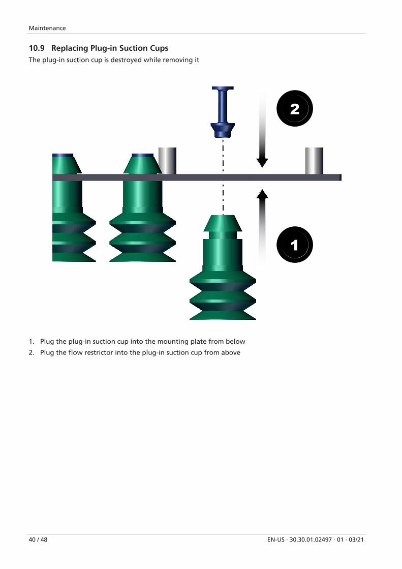
10.9 Replacing Plug-in Suction CupsThe plug-in suction cup is destroyed while removing it
1
2
1. Plug the plug-in suction cup into the mounting plate from below
2. Plug the flow restrictor into the plug-in suction cup from above

Maintenance
EN-US · 30.30.01.02497 · 01 · 03/21 41 / 48
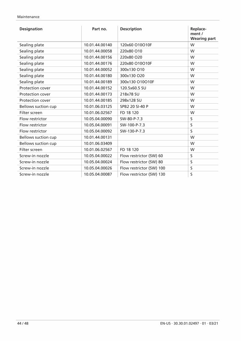
10.10 Accessories, Spare Parts and Wearing PartsAccessories, spare parts and wearing parts can be requested from the Schmalz service team using the or-der number, product key or product service number.
General Accessories
Designation Part no. Note
Connection cable 21.04.05.00080 Straight
Connection cable 21.04.05.00557 Angled
Vacuum hose 10.07.09.00001 VSL 4-2 PU
Vacuum hose 10.07.09.00002 VSL 6-4 PU
Vacuum hose 10.07.09.00003 VSL 8-6 PU
Vacuum hose 10.07.09.00083 VSL 10-7
Vacuum hose 10.07.09.00037 VSL 12-9 PU
Vacuum hose 10.07.09.00038 VSL 14-11 PU
Vacuum hose 10.07.09.00007 VSL 26-19 PVC-DS
Vacuum gauge (manometer) 10.01.44.00249 Analog
Vacuum/pressure switch 10.06.02.00577 VSi
Accessories for 120x60 Gripper Size
Designation Part no. Note
Spring plunger 10.01.02.00602 FSTE, 1/8" external thread, 15
Spring plunger 10.01.02.00605 FSTE, 1/8" external thread, 15 VG
Spring plunger 10.01.02.00603 FSTE, 1/8" external thread, 25
Spring plunger 10.01.02.00604 FSTE, 1/8" external thread, 50
Spring plunger 10.01.02.00606 FSTE, 1/8" external thread, 50 VG
Spring plunger 10.01.02.00756 FSTE-HD, 1/8" external thread, 15
Spring plunger 10.01.02.00872 FSTE-HD, 1/8" external thread, 15 VG
Spring plunger 10.01.02.00757 FSTE-HD, 1/8" external thread, 25
Spring plunger 10.01.02.00873 FSTE-HD, 1/8" external thread, 25 VG
Spring plunger 10.01.02.00758 FSTE-HD, 1/8" external thread, 50
Spring plunger 10.01.02.00874 FSTE-HD, 1/8" external thread, 50 VG
Ball joint 10.01.03.00109 KGL, 1/8", A2
Flange module 10.01.44.00195 FQE 2x connection, 120x60 incl. screws
Flange module 10.01.44.00194 FQE 3x connection, 120x60
Flange module 10.01.44.00193 FQE 4x connection, 120x60
Basic ejector 10.02.01.00565 SBP 10
Basic ejector 10.02.01.00566 SBP 15
Vacuum filter (inline) 10.07.01.00328 VFI 6/4 50
Solenoid valve 10.05.02.00162 EMVP 5 3/2 NC
Accessories for 220x80/300x130
Designation Part no. Note
Spring plunger 10.01.02.00567 FSTE 1/4" external thread, 25 (2,400 N)
Spring plunger 10.01.02.00568 FSTE, 1/4" external thread, 50 (2,400 N)
Spring plunger 10.01.02.00569 FSTE, 1/4" external thread, 75 (2,400 N)
Spring plunger 10.01.02.00570 FSTE, 1/4" external thread, 25 VG (2,400 N)
Maintenance
42 / 48 EN-US · 30.30.01.02497 · 01 · 03/21
Designation Part no. Note
Spring plunger 10.01.02.00571 FSTE, 1/4" external thread, 75 VG (2,400 N)
Spring plunger 10.01.02.00763 FSTE-HD, 1/4" external thread, 25 (2,400 N)
Spring plunger 10.01.02.00764 FSTE-HD, 1/4" external thread, 50 (2,400 N)
Spring plunger 10.01.02.00765 FSTE-HD, 1/4" external thread, 75 (2,400 N)
Spring plunger 10.01.02.00875 FSTE-HD, 1/4" external thread, 25 VG (2,400 N)
Spring plunger 10.01.02.00876 FSTE-HD, 1/4" external thread, 50 VG (2,400 N)
Spring plunger 10.01.02.00877 FSTE-HD, 1/4" external thread, 75 VG (2,400 N)
Spring plunger 10.01.02.01056 FSTE-HD, 1/4" external thread, 90 VG (1,500N)
Spring plunger 10.01.02.00574 FSTE 1/2" external thread, 25 (4,900N)
Spring plunger 10.01.02.00575 FSTE, 1/2" external thread, 75 (4,900N)
Spring plunger 10.01.02.00576 FSTE, 1/2" external thread, 90 (4,900N)
Spring plunger 10.01.02.00770 FSTE-HD, 1/2" external thread, 25 (4,900N)
Spring plunger 10.01.02.00771 FSTE-HD, 1/2" external thread, 75 (4,900N)
Spring plunger 10.01.02.00772 FSTE-HD, 1/2" external thread, 90 (4,900N)
Spring plunger 10.01.02.00881 FSTE-HD, 1/2" external thread, 25 VG (4,900N)
Spring plunger 10.01.02.00882 FSTE-HD, 1/2" external thread, 75 VG (4,900N)
Spring plunger 10.01.02.00883 FSTE-HD, 1/2" external thread, 90 VG (4,900N)
Flexolink 10.01.03.00178 FLK, 1/4" internal thread, 1/4" external thread
Flexolink 10.01.03.00175 FLK, 1/2" internal thread, 1/2" external thread
Ball joint 10.01.03.00110 KGL, 1/4" internal thread, 1/4" external thread
Ball joint 10.01.03.00111 KGL, 1/2" internal thread, 1/2" external thread
Flange module 10.01.44.00203 2x connection module, 220x80
Flange module 10.01.44.00209 3x connection module, 220x80
Flange module 10.01.44.00208 4x connection module, 220x80
Flange module 10.01.44.00202 2x connection module, 300x130
Flange module 10.01.44.00210 3x connection module, 300x130
Flange module 10.01.44.00205 4x connection module, 300x130
Flange module 10.01.44.00204 1/4" spring plunger adapter
Flange module 10.01.44.00212 1/2" spring plunger adapter
Basic ejector 10.07.01.00122 SBPL 50 HF
Basic ejector 10.07.01.00123 SBPL 75 HF
Basic ejector 10.07.01.00128 SBPL 100 HF
Vacuum cup filter 10.07.01.00122 VFT, 3/8" internal thread, 80
Vacuum cup filter 10.07.01.00128 VFT, 3/4" internal thread, 80
Vacuum cup filter 10.07.01.00123 VFT, 3/8" internal thread, 100
Solenoid valve 10.05.02.00144 EMVP 10 3/2 NO/NC
Solenoid valve 10.05.02.00146 EMVP 15 NO/NC
Solenoid valve 10.05.02.00149 EMVP 20 3/2 NO/NC
Spare and Wearing Parts
Designation Part no. Description Replace-ment /Wearing part
Sealing plate (FQE) 10.01.44.00047 Sealing for suction trough, 120x60 S
Sealing plate (FQE) 10.01.44.00037 Sealing for suction trough, 220x80 S
Maintenance
EN-US · 30.30.01.02497 · 01 · 03/21 43 / 48
Designation Part no. Description Replace-ment /Wearing part
Sealing plate (FQE) 10.01.44.00050 Sealing for suction trough,300x130
S
Ejector module 10.02.01.01343 SEP HF 2 06 13 S
Ejector module 10.02.01.01347 SEP HF 2 13 22 S
Plug 10.01.44.00061 Instead of ejector module 2-13-22 S
Silencer insert 10.01.44.00021 for 120x60 S
Silencer insert 10.01.44.00116 for large version/Set – consisting of 4 parts
S
Silencer cap 10.01.44.00001 small S
Silencer cap 10.01.44.00030 large S
Plug-in screw union, straight 10.08.02.00200 M5 AG4 S
Sealing screw with collar 10.08.06.00064 M5 S
Plug-in screw union, bracket 10.08.02.00155 M5 AG4 S
Plug-in screw union, straight 10.08.02.00204 STV-GE, 1/8" external thread, 6 S
Plug-in screw union, bracket 10.08.02.00158 STV-W, 1/8" external thread, 6 S
Plug-in screw union, straight 10.08.02.00206 1/8" external thread, 8 S
Plug-in screw union, bracket 10.08.02.00160 1/8" external thread, 8 S
Plug-in screw union, straight 10.08.02.00202 1/8" external thread, 4 S
Sealing screw with collar 10.08.06.00043 1/8" S
Plug-in screw union, bracket 10.08.02.00156 1/8" external thread, 4 S
Plug-in screw union, straight 10.08.02.00207 STV-GE, 1/4" external thread, 8 S
Plug-in screw union, bracket 10.08.02.00161 STV-W, 1/4" external thread, 8 S
Plug-in screw union, bracket 10.08.02.00171 STV-WF, 1/4" external thread, 8 S
Plug-in screw union, straight 10.08.02.00128 STV-GE, 1/4" external thread, 10 S
Plug-in screw union, bracket 10.08.02.00254 STV-W, 1/4" external thread, 10 S
Plug-in screw union, bracket 10.08.02.00258 STV-WF, 1/4" external thread, 10 S
Plug-in screw union, straight 10.08.02.00210 STV-GE, 1/2" external thread, 12 S
Plug-in screw union, bracket 10.08.02.00164 STV-W, 1/2" external thread, 12 S
Plug-in screw union, straight 10.08.02.00300 STV-GE, 1/2" external thread, 14 S
Plug-in screw union, bracket 10.08.02.00273 STV-W, 1/2" external thread, 14 S
Hose sleeve 10.08.03.00163 ST, 1/2" external thread, 19 MS-V S
Machine screw 20.01.02.00504 for silencer cap, 120x60 S
Machine screw 20.01.02.04002 for silencer cap, 220x80/300x130(identical)
S
Machine screw 20.01.02.00001 M3x10 attachment, mountingplate to suction trough, 120x60
S
Machine screw 20.01.02.00002 M3x12 attachment, mountingplate to suction trough,220x80/300x130
S
Machine screw 20.01.02.00006 M3x16 attachment, mountingplate to suction trough, FQE-M(FM), 300x130
S
Safety washer 20.06.02.00027 for 120x60 S
Sealing plate 10.01.44.00007 120x60 O10 W
Sealing plate 10.01.44.00137 120x60 O20 W
Maintenance
44 / 48 EN-US · 30.30.01.02497 · 01 · 03/21
Designation Part no. Description Replace-ment /Wearing part
Sealing plate 10.01.44.00140 120x60 O10O10F W
Sealing plate 10.01.44.00058 220x80 O10 W
Sealing plate 10.01.44.00156 220x80 O20 W
Sealing plate 10.01.44.00176 220x80 O10O10F W
Sealing plate 10.01.44.00052 300x130 O10 W
Sealing plate 10.01.44.00180 300x130 O20 W
Sealing plate 10.01.44.00189 300x130 O10O10F W
Protection cover 10.01.44.00152 120.5x60.5 SU W
Protection cover 10.01.44.00173 218x78 SU W
Protection cover 10.01.44.00185 298x128 SU W
Bellows suction cup 10.01.06.03125 SPB2 20 SI-40 P W
Filter screen 10.01.06.02567 FD 18 120 W
Flow restrictor 10.05.04.00090 SW-80-P-7.3 S
Flow restrictor 10.05.04.00091 SW-100-P-7.3 S
Flow restrictor 10.05.04.00092 SW-130-P-7.3 S
Bellows suction cup 10.01.44.00131 W
Bellows suction cup 10.01.06.03409 W
Filter screen 10.01.06.02567 FD 18 120 W
Screw-in nozzle 10.05.04.00022 Flow restrictor (SW) 60 S
Screw-in nozzle 10.05.04.00024 Flow restrictor (SW) 80 S
Screw-in nozzle 10.05.04.00026 Flow restrictor (SW) 100 S
Screw-in nozzle 10.05.04.00087 Flow restrictor (SW) 130 S

Disposing of the Product
EN-US · 30.30.01.02497 · 01 · 03/21 45 / 48
11 Disposing of the ProductRecover the disassembled parts for recycling or reuse (provided no agreement on return or disposal hasbeen made).
1. Dispose of the product properly after replacement or decommissioning.
2. Observe the country-specific guidelines and legal obligations for waste prevention and disposal.
EC Conformity
46 / 48 EN-US · 30.30.01.02497 · 01 · 03/21
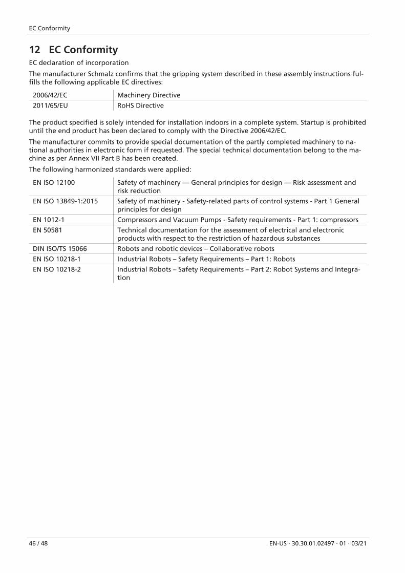
12 EC ConformityEC declaration of incorporation
The manufacturer Schmalz confirms that the gripping system described in these assembly instructions ful-fills the following applicable EC directives:
2006/42/EC Machinery Directive
2011/65/EU RoHS Directive
The product specified is solely intended for installation indoors in a complete system. Startup is prohibiteduntil the end product has been declared to comply with the Directive 2006/42/EC.
The manufacturer commits to provide special documentation of the partly completed machinery to na-tional authorities in electronic form if requested. The special technical documentation belong to the ma-chine as per Annex VII Part B has been created.
The following harmonized standards were applied:
EN ISO 12100 Safety of machinery — General principles for design — Risk assessment andrisk reduction
EN ISO 13849-1:2015 Safety of machinery - Safety-related parts of control systems - Part 1 Generalprinciples for design
EN 1012-1 Compressors and Vacuum Pumps - Safety requirements - Part 1: compressors
EN 50581 Technical documentation for the assessment of electrical and electronicproducts with respect to the restriction of hazardous substances
DIN ISO/TS 15066 Robots and robotic devices – Collaborative robots
EN ISO 10218-1 Industrial Robots – Safety Requirements – Part 1: Robots
EN ISO 10218-2 Industrial Robots – Safety Requirements – Part 2: Robot Systems and Integra-tion

30.30.01.02497 · 01 · 03/21 47 / 48

© J
. Sch
mal
z G
mb
H ·
EN-U
S · 3
0.30
.01.
0249
7 · 0
1 · 0
3/21
· Su
bje
ct t
o t
ech
nic
al c
han
ges
wit
ho
ut
no
tice