Embed Size (px)
Citation preview

sun® microsystems
Assembly Language Reference for the Sun-2™ and Sun-3™
Part Number: 800-1773-10 Revision A, of9 May 1988

Sun Workstation® and Sun Microsystems® are registered trademarks of Sun Microsystems, Inc.
Sun ViewTM, SunOSTM, Sun386iTM, and the combination of Sun with a numeric suffix are trademarks of Sun Microsystems, Inc.
UNIX is a registered trademark of AT&T Bell Laboratories.
All other products or services mentioned in this document are identified by the trademarks or service marks of their respective companies or organizations.
Copyright© 1987, 1988 by Sun Microsystems, Inc.
This publication is protected by Federal Copyright Law, with all rights reserved. No part of this publication may be reproduced, stored in a retrieval system, translated, transcribed, or transmitted, in any form, or by any means manual, electric, electronic, electro-magnetic, mechanical, chemical, optical, or otherwise, without prior explicit written permission from Sun Microsystems. (~.
~)

Contents
Chapter 1 Introduction .......................................................................................................... 3
1.1. Using the Assembler...................................................................................................... 3
1.2. Notation................................................................................................................................. 4
Chapter 2 Elements of Assembly Language ........................................................ 9
2.1. Character Set...................................................................................................................... 9
2.2. Identifiers .............................................................................................................................. 9
2.3. Numeric Labels................................................................................................................. 10
2.4. Local Labels ....................................................................................................................... 10
2.5. Scope of Labels ................................................................................................................ 10
2.6. Constants .............................................................................................................................. 11
2. 7. Numeric Constants .......................................................................................................... 11
2.8. String Constants ............................................................................................................... 12
2.9. Assembly Location Counter ...................................................................................... 12
Chapter 3 Expressions ........................................................................................................... 17
3.1. Operators 17
3.2. Terms 18
3.3. Expressions ....................... .
3.4. Absolute, Relocatable, and External bxpressHJll.S
Chapter 4 Assembly Language Program
4.1. Label Field
4.2. Operation Code Field ............................................. .
-iii-

Contents - Continued
(\
4.3. Operand Field ................................................................................................................... . 25 \'-· /
4.4. Comment Field ................................................................................................................ . 26
4.5. Direct Assignment Statements ................................................................................ . 26
Chapter 5 Assembler Directives ................................................................................... . 31 5.1. . ascii- Generate Character Data ............................................................... . 32
5 .2. . asci z - Generate Zero-Terminated Sequence of Character Data ......................................................................................................................................... . 33
5.3. Directives to Generate Data ...................................................................................... . 33
5.4. Directives to Switch Location Counter .............................................................. . 34
5.5. . skip- Advance the Location Counter .................................................... . 35
5.6. .lcornm- Reserve Space in bss Area ...................................................... . 35
5.7. . globl- Designate an External Identifier ............................................. ... 36
5.8. . cornm- Define Name and Size of a Common Area ........................... . 36
5.9. . align- Force Location Counter to Particular Byte Boundary ............................................................................................................................. . 37
5.10. . even- Force Location Counter to Even Byte Boundary ............ . 37
5.11. . s tabx- Build Special Symbol Table Entry ....................................... . 37 I~
\__") 5.12. . proc- Separate Procedures for Span-Dependent
Instruction Resolution ............................................................................................... . 38
5.13. . cpid-Name Default CoprocessoriD .................................................. . 38
Chapter 6 Instructions and Addressing Modes ................................................. . 41 6.1. Instruction Mnemonics ... .: ........................................................................................... . 41
6.2. Extended Branch Instruction Mnemonics ........................................................ . 41 \
6.3. Addressing Modes .......................................................................................................... . 42~
6.4. Addressing Categories ................................................................................................. . 46
Appendix A .as Error Codes ............................................................................................ . 51 A.1. Usage Errors ..................................................................................................................... . 51
A.2. Assembler Error Messages ....................................................................................... . 51
Appendix B List of as Opcodes ................................................................................. . 59
-iv-

Contents- Continued
Appendix C FPA Assembler Syntax .......................................................................... 83
C.1. Instruction Syntax .......................................................................................................... 83
C.2. Register Syntax ................................................................................................................ 84
C.3. Operand Types ................................................................................................................. 84
C.4. Two-Operand Instructions ......................................................................................... 84
C.5. Three-Operand Instructions ...................................................................................... 85
C.6. Four-Operand Instructions ......................................................................................... 86
C. 7. Other Instructions ........................................................................................................... 90
C.8. Restrictions and Errors ................................................................................................ 91
C.9. Instruction Set Summary............................................................................................ 91
Index....................................................................................................................................................... 95
c -v-

i ~ I
f

Tables
Table 3-1 Unary Operators in Expressions ...................................................................... 17
Table 3-2 Binary Operators in Expressions..................................................................... 17
Table 5-l Assembler Directives ............................................................................................. 31
Table 6-1 Addressing Modes ................................................................................................... 44
Table 6-2 Addressing Categories .......................................................................................... 46
Table B-1 List of MC680x0 Instruction Codes ............................................................. 60
Table B-2 MC68881 Instructions supported by as .................................................. 68
Table C-1 Other Instructions .................................................................................................... 92
Table C-2 Floating-Point Instructions ................................................................................ 93
-vii-

What as Provides
Scope of This Manual
Audience
Further Reading
Preface
This manual is the Programmer's Reference Manual for as -the assembler for Sun-2 and Sun-3 workstations running the SunOS operating system. as converts source programs written in assembly language into a form that the linker utility, ld(l) will tum into a rurmable program.
as provides assembly language programmers with a minimal set of facilities to write programs in assembly language. Since most programming is done in highlevel languages, as doesn't provide any elaborate macro facilities or conditional assembly features. It is assumed that the volume of assembly code produced is so small that these facilities aren't required. If they are needed, you can use the C preprocessor (see cpp(l)) to provide them.
This manual describes the syntax and usage of the as assembler for the Motorola MC68010 and MC68020 microprocessors, the MC68881 floating-point coprocessor, and Sun's Floating-Point Accelerator (FPA). The basic format of as is loosely based on the Digital Equipment Corporation's Macro-11 assembler described in DEC's publication DEC-11-0MACA-A-D. It also contains elements of the UNIXt PDP-11 as assembler. The instruction mnemonics and effective address format are based on a Motorola publication on the MC68000: the MACSS MC68000 Design Specification Instruction Set Processor dated June 30, 1979.
This is a reference manual as opposed to a treatise on writing in a§§embly language. It assumes that you are familiar with the concepts of n.t~cfijge architecture, the reasons for an assembler, the ideas of instruction mpefugffiq§, ()perands, and effective address modes, and assembler directives. It~sq ~ssj.l,giey>i.fi~tyou are familiar with the relevant processors, their instructiqtf §~ts aijg. ~~dr~~$iHg ? modes, and especially their irregularities. .··.·.·.·.· .··.·.·.··.· ··.··.·.······.· ··.····· ······
Motorola MC68010 16-bit Microprocessor Progr~~~~~~~fJ;endg~:~~ >
Motorola MC68020 32-bit Microprocessor User's ManuJ: < .. } >
Motorola MC68881 Floating-Point Coprocessor User's Man~~l ) .
t UNIX is a registered trademarlc of AT&T.
-ix-


1 Introduction
Introduction ....................................................................................................................................... 3
1.1. Using the Assembler...................................................................................................... 3
1.2. Notation ................................................................................................................................ ; 4

(\ \ J '--· ,/

1.1. Using the Assembler
1 Introduction
By convention, the assembly language source code of the program should be in one or more files with a . s suffix. Suppose that your program is in two files called parts. sand rest. s. To run the assembler, type the command:
[tutorial% as parts.s rest.s
as runs silently (if there are no errors), and generates a file called a . out.
as also accepts several command-line options. These are:
-ofile Place the output of the assembler infile instead of a.out.
-m68010 This is the default on Sun-2 systems. Accept only the MC68010 instruction set and addressing modes. This also puts the MC68010 machine type tag into the a.out file.
-m68020 This is the default on Sun-3 systems. Accept the full MC68020, MC68881, and Sun FPA instruction sets and addressing modes. Includes the MC68010 instruction set and addressing modes as a subset, and also puts the MC68020 machine type tag into the a.out file.
-k Generate position-independent code as required by
( cc -pic/-PIC
l
l WARNING Don't apply this flag to hand-coded ,assembler programs unless they are written
to be position-independent.
-o Perform span-dependent instruction resolution over each entire file, rather than just over each procedure (see the description of the .proc pseudo-operation in Chapter 5).
-R Make initialized data segments read-only (actually the assembler places them at the end of the . text area).
-L Keep local (compiler-generated) symbols that start with the letter L. This is a debugging feature. If the -L option is omitted, the assembler discards those symbols and does not include them in the symbol table.
3 Revision A of May 9, 1988

-------~- --~~-
4 Assembly Language Reference
1.2. Notation
-j Make all jumps to external symbols ( j sr and jmp) PC-relative rather than long-absolute. This is intended for use when the programmer knows that the program is short, since it only permits jumps (forward or back) up to 32K bytes long. If there are any externals which are too far away, the loader will complain when the program is linked.
-J Suppress span-dependent instruction calculations and force all branches and calls to take the most general form. This is used when assembly time must be minimized, but program size and run time are not important.
-h Suppress span-dependent instruction calculations and force all branches to be of medium length, but all calls to take the most general form. This is used when assembly time must be minimized, but program size and running time are not important. This option results in a smaller and faster program than that produced by the -J option, but some very large programs may not be able to use it because of the limits of the medium-length branches.
-d2 This is intended for small stand-alone programs. The assembler makes all program references PC-relative and all data references short-absolute. Note that the -j option does half this job.
You should also consult the SunOS Reference Manual entry on as.
The notation used in this manual is a somewhat modified Backus-N aur Form (BNF). A string of characters on its own stands for itself, for example:
(WIDGET
is an occurrence of the literal string 'WIDGET', and:
J
(~19-83----------------------~J is an occurrence of the literal constant 1983. An element enclosed in< and> signs is a non-terminal symbol, and must eventually be defined in terms of some other entities. For example,
(<identifier>
stands for the syntactic construct called 'identifier', which is eventually defined in terms of basic objects. A syntactic object followed by an ellipsis:
J
[~<-t-hl-·n-g> ___ • __ • __ • ____________________________________________ ~] denotes one or more occurrences of <thing>. Syntactic objects occurring one after the other, as in:
sun microsystems
Revision A of May 9, 1988

Chapter 1 -Introduction 5
(~<-fi~r-~_t_m_n_g~> _____ <_s_e_co_n_d_t_hz_·n_g_> ________________________________ ~] simply means an occurrence of first thing followed by second thing. Syntactic elements separated by a vertical bar sign ( I ), as in:
( <letter> 1 <digit> J ~' --------mean an occurrence of <letter> or <digit> but not both. Brackets and braces define the order of interpretation. Brackets also indicate that the syntax described by the subexpression they enclose is optional. That is:
( [ <thing> J
denotes zero or one occurrences of <thing>, while { and } are used for grouping so that
J
( ~ <thing one> 1 <thing two> } <thing three> J '----' --------denotes a <thing one> or a <thing two>, followed by a <thing three>.
Revision A of May 9, 1988

(\ \...,./
!'\. I I
\__j

2 Elements of Assembly Language
Elements of Assembly Language ..................................................................................... 9
2.1. Character Set ...................................................................................................................... 9
2.2. Identifiers .............................................................................................................................. 9
2.3. Numeric Labels................................................................................................................. 10
2.4. Local Labels ....................................................................................................................... 10
2.5. Scope ofLabels ................................................................................................................ 10
2.6. Constants .............................................................................................................................. 11
2.7. Numeric Constants .......................................................................................................... 11
2.8. String Constants ............................................................................................................... 12
2.9. Assembly Location Counter...................................................................................... 12
c


2.1. Character Set
2.2. Identifiers
c
2 Elements of Assembly Language
This chapter covers the lexical elements which comprise an assembly language program. (Chapter 3 discusses the rules for expression and operand formation.) Topics covered in this chapter are:
o The character set that the assembler recognizes,
o Rules for identifiers and labels,
o Syntax for numeric constants,
o Syntax for string constants,
o The assembly location counter.
An assembly language program is ultimately constructed from characters. Characters are combined to make up lexical elements or tokens of the language. Combinations of tokens form assembly language statements, and sequences of statements form an assembly language program. This section describes the basic lexical elements of as.
as recognizes the following character set:
o The letters A through z and a through z.
o The digits 0 through 9.
o The ASCII graphic characters- the printing characters other than letters and digits.
o The ASCII non-graphics: space, tab, carriage return, and newline (also known as linefeed).
Identifiers are used to tag assembler statements (where they are called labels), as location tags for data, and as the symbolic names of constants.
An identifier in an as program is a sequence of from 1 to 255 characters from the set:
o Upper case letters A through z. o Lower case letters a through z.
o Digits 0 through 9.
9 Revision A of May 9, 1988

10 Assembly Language Reference
2.3. Numeric Labels
2.4. Local Labels
2.5. Scope of Labels
o The characters underline ( ), period ( . ), and dollar sign ( $).
The first character of an identifier must not be numeric. Other than that restriction, there are a few other points to note:
o All characters of an identifier are significant and are checked in comparisons with other identifiers.
o Upper case letters and lower case letters are distinct, so that kit_of_parts and KIT_OF_PARTS are two different identifiers.
o Although the period ( .) and dollar sign ( $) characters can be used to construct identifiers, they are reserved for special purposes (pseudo-ops for instance) and should not appear in user-defined identifiers.
Here are some examples of legal identifiers:
Grab Hold Widget Pot_of_Message MAXNAME
A numeric label consists of a digit (0 to 9) followed by a colon. As in the case of alphanumeric labels, a numeric label assigns the current value of the location counter to the symbol. However, several numeric labels with the same digit may be used within the same assembly. References of the fonn nb refer to the first numeric label named n backwards from the reference; n f symbols refer to the first numeric label named nforwards from the reference.
Local labels are a special fonn of identifier which are strictly local to a control section (see Section 5.4). Local labels provide a convenient means of generating labels for branch instructions arid such. Use of local labels reduces the possibility of multiply defined labels in a program, and separates entry point labels from local references, such as the top of a loop. Local labels cannot be referenced from outside the current assembly unit. Local labels are of the fonn n$ where n is any integer. Valid local labels include:
[ 1$ 27$ 394$
The scope of a label is the 'distance' over which it is visible to other parts of the program which may reference it. An ordinary label which tags a location in the program or data is visible only within the current assembly. An identifier which is designated as an external identifier via a . globl directive is visible to other assembly units at link time.
l
Local labels have a scope, or span of reference, which extends between one ordinary label and the next. Every time an ordinary label is encountered, all previous
sun microsystems
Revision A of May 9, 1988

c first: addl dO,d1
100$: addqw #7,d3 bees 100$
second: andl #Ox7ff,d4
100$: cmpw d1,d3 beqs 100$
third: movw dO,d7 beqs 100$
c 2.6. Constants
2.7. Numeric Constants
c
Chapter 2- Elements of Assembly Language 11
local labels associated with the current location counter are discarded, and a new local label scope is created. The following example illustrates the scopes of the different kinds of labels:
creates a new local label scope
first appearance of 100$ branches to the label above
above 100$ has gone away
this is a different 100$ branches to the previous instruction
now 100$ has gone away again generates an error message if no 100$ below
The labels first, second, and third all have a scope which is the entire source file containing them. The first appearance of the locallabell 0 0 $ has a scope which extends between first and second. The second appearance of the locallabell 0 0 $ has a scope which extends between second and third. After the appearance of the label third, the branch to 1 0 0 $ will generate an error message because that label is no longer defined in this scope.
There are two forms of constants available to as users, namely numeric constants and string constants. All constants are considered absolute quantities when they appear in an expression (see Section 3.4 for a discussion on absolute and relocatable expressions).
as assumes that any token which starts with a digit is a numeric constant. as accepts numeric quantities in decimal (base 10), hexadecimal (base 16), or octal (base 8) radices. Numeric constants can represent quantities up to 32 bits in length.
Decimal numbers consist of between one and ten decimal digits (in the range 0 through 9). The range of decimal numbers is between -2,147,483,648 and 2,147,483,647. Note that you can't have commas in decimal numbers even though they are shown here for readability. Note also that decimal numbers can't be written with leading zeros, because a numeric constant starting with a zero is taken as either an octal constant or a hexadecimal constant, as described below.
Hexadecimal constants start with the notation Ox or OX (zero-ex) and can then have between one and eight hexadecimal digits. The hexadecimal digits consist of the decimal digits 0 through 9 and the hexadecimal digits a through for A through F.
Octal constants start with the digit 0. There can then be from one to 11 octal digits (0 through 7) in the number. But note that 11 octal digits is 33 bits, so the largest octal number is 037777777777.
sun microsystems
Revision A of May 9, 1988

12 Assembly Language Reference
2.8. String Constants
2.9. Assembly Location Counter
01 Floating-point constants must start with #Or or #OR, which may be followed by \_/; an optional sign and either a number, an infinity or a nan ("not a number"). The syntax is
[ {fOr I :ftOR} [+ I -] {<number> I inf I nan} J where the syntax of a <number> is
{<digits> [ . [<digits>] ] I • <digits>} [ E [ + I -] <digits>]
and <digits> is a string of decimal digits.
A string is a sequence of ASCII characters, enclosed in quote signs ".
Within string constants, the quote sign is represented by a backslash character followed by a quote sign. The backslash character itself is represented by two backslash characters. Any other character can be represented by a backslash character followed by one, two, or three octal digits, or by a backslash followed by 0 x or 0 x and a one- or two-digit hexadecimal constant. The table below shows the octal representation of some of the more common non-printing characters.
Character Octal Hex
Backspace \010 Ox8
Horizontal Tab \011 Ox9
Newline (Linefeed) \012 OxA
Formfeed \014 OxC
Carriage Return \015 OxD
The assembly location counter is the period character ( • ). It is colloquially known as dot. When used in the operand field of any statement, dot represents the address of the first byte of the statement. Even in assembler directives, dot represents the address of the start of that assembler directive. For example, if dot appears as the third argument in a .long directive, the value placed at that location is the address of the first location of the directive - dot is not updated until the next machine instruction or assembler directive. For example:
Ralph: movl .,aO load value of Ralph into aO
sun microsystems
Revision A of May 9, 1988

----'-------1.-J~-<~--"""'"'='~,..,--,.,-a ......, ... __ ..,,_w•-•u-lij __ .,,,._..,,...,.< ..,t!::l...,!~~-l...,ua_,_,_"""'""<,..*=""'sttt..,!>!!tl.., ....._ __________ _
c Chapter 2-Elements of Assembly Language 13
You can reserve storage by advancing dot. For example, the statement
(Table: .=.+OxlOO ) reserves 256 bytes (100 hexadecimal) of storage, with the address of the first byte as the value of Table. This is exactly equivalent to using . skip (the preferred syntax) as follows:
(Table: . skip OxlOO
The value of dot is always relative to the start of the current control section. For example,
)
( . = OxlOOO )
doesn't set dot to absolute location OxlOOO, but to location OxlOOO relative to the start of the current control section. This practice is not recommended.
Revision A of May 9, 1988


c 3
Expressions
Expressions ....................................................................................................................................... 17
3.1. Operators .............................................................................................................................. 17
3.2. Terms ...................................................................................................................................... 18
3.3. Expressions ......................................................................................................................... 18
3.4. Absolute, Relocatable, and External Expressions......................................... 18

0

3.1. Operators
Table 3-1
3 ••• !>··:t:·:::
Expressions
Expressions are combinations of operands (numeric constants and identifiers) and operators, forming new values. The sections below define the operators which as provides, then gives the rules for combining terms into expressions.
Identifiers and numeric constants can be combined, via arithmetic operators, to · form expressions. as provides unary operators and binary operators, as described below.
Unary Operators in Expressions
Operator Function Description
- unary minus Two's complement of its argument.
- logical negation One's complement (logical negation) of its argu-ment.
Table 3-2 Binary Operators in Expressions
Operator Function Description
+ addition Arithmetic addition of its arguments.
- subtraction Arithmetic subtraction of its arguments.
* multiplication Arithmetic multiplication of its arguments.
I division Arithmetic division of its arguments. Note that division in as is integer division, which trun-cates towards zero.
Each operator works on 32-bit numbers. If the value of a particular term occupies only 8 bi.ts or 16 bits, it is sign extended to a full 32-bit value.
sun microsystems
17 Revision A of May 9, 1988

18 Assembly Language Reference
3.2. Terms
3.3. Expressions
3.4. Absolute, Relocatable, and External Expressions
A term is a component of an expression. A term may be any of the following:
o A numeric constant, whose 32-bit value is used. The assembly location counter, known as dot, is considered a number in this context
o An identifier.
o An expression or term enclosed in parentheses ( ) . Any quantity enclosed in parentheses is evaluated before the rest of the
expression. This can be used to alter the normal1eft-to-right evaluation of expressions- for example, differentiating between a *b+c and a* (b+c) or to apply a unary operator to an entire expression- for example, - (a*b+c).
o A term preceded by a unary operator. For example, both double_plus_ungood and -double_plus_ungood are terms.
Multiple unary operators can be used in a term. For example, - -positive has the same value as positive.
Expression are combinations of terms joined together by binary operators. An expression is always evaluated to a 32-bit value.
If the operand requires only a single-byte value (a . byte directive or an addq instruction, for example) the low-order eight bits of the expression are used.
If the operand requires only a 16-bit value (a . word directive or a movem c/: instruction, for example) the low-order 16 bits of the expression are used. __ -
Expressions are evaluated left to right with no operator precedence. Thus
J evaluates to 9, not 7. Unary operators have precedence over binary operators since they are considered part of a term, and both terms of a binary operator must be evaluated before the binary operator can be applied.
A missing expression or term is interpreted as having a value of zero. In this case, an Invalid expression error is generated.
An Invalid Operator error means that a valid end-of-line character or binary operator was not detected after the assembler processed a term. In particular, this error is generated if an expression contains an identifier with an illegal character, or if an incorrect comment character was used.
When an expression is evaluated, its value is either absolute, relocatable, or external:
An expression is absolute if its value is fixed.
o An expression whose terms are constants is absolute.
o An identifier whose value is a constant via a direct assignment statement is absolute.
sun microsystems
Revision A of May 9, 1988

c Chapter 3 - Expressions 19
o A relocatable expression minus a relocatable term is absolute, if both items belong to the same program section.
An expression is relocatable if its value is fixed relative to a base address, but will have an offset value when it is linked or loaded into memory. All labels of a program defined in relocatable sections are relocatable terms.
Expressions which contain relocatable terms must only add or subtract constants to their value. For example, assuming the identifiers widget and bli vet were defined in a relocatable section of the program, then the following demonstrates the use of relocatable expressions:
Expression Description
widget is a simple relocatable term. Its value is an offset from the base address of the current control section.
widget+S is a simple relocatable expression. Since the value of widget is an offset from the base address of the current control section, adding a constant to it does not change its relocatable status.
widget*2 Not relocatable. Multiplying a relocatable term by a constant invalidates the relocatable status.
2-widget Not relocatable, since the expression cannot be linked by adding widget's offset to it.
widget-blivet Absolute, since the offsets added to widget and blivet cancel each other out.
An expression is external (or global) if it contains an external identifier not defined in the current program. With one exception, the same restrictions on expressions containing relocatable identifiers apply to expressions containing external identifiers. The exception is that the expression
( widget-bli vet
is incorrect when both widget and bli vet are external identifiers- you cannot subtract two external relocatable expressions. In addition, you cannot multiply or divide any relocatable expression.
J
sun microsystems
· Revision A of May 9, 1988


4 Assembly Language Program Layout
Assembly Language Program Layout .......................................................................... 23
4.1. Label Field........................................................................................................................... 23
4.2. Operation Code Field .................................................................................................... 24
4.3. Operand Field .................................................................................................................... 25
4.4. Comment Field ................................................................................................................. 26
4.5. Direct Assignment Statements ................................................................................. 26
(~


----·-------~~-~2> - -~L2£11i>WI,J!&i!l$li - ...
4.1. Label Field
4 Assembly Language Program Layout
An as program consists of a series of statements. Several statements can be written on one line, but statements cannot cross line boundaries. The format of a statement is:
[ < label field>] [ < ope ode> [<operand field>] ]
It is possible to have a statement which consists of only a label field.
The fields of a statement can be separated by spaces or tabs. There must be at least one space or tab separating the opcode field from the operand field, but spaces are unnecessary elsewhere. Spaces may appear in the operand field. Spaces and tabs are significant when they appear in a character string (for instance, as the operand of an . ascii pseudo-op) or in a character constant. In these cases, a space or tab stands for itself.
A line is a sequence of zero or more statements, optionally followed by a comment, ending with a < newline> character. A line can be up to 4096 characters long. Multiple statements on a line are separated by semicolons. Blank lines are allowed. The form of a line is:
[<statement> [ ; <statement> ... ] ] [ I < comment> ]
Labels are identifiers which the programmer may use to tag the locations of program and data objects. The format of a <label field> is:
[ ~identifier> [ <identifier> ] . . . ]
.._______ __ _____ If present, a label always occurs first in a statement and must be terminated by a colon:
[sticky: label defined here. )
sun microsystems
23 Revision A of May 9, 1988
24 Assembly Language Reference
4.2. Operation Code Field
More than one label may appear in the same source statement, each one being terminated by a colon:
presson: grab: hold: multiple labels defined here.
The collectiol!_ of label definitions in a statement is called the label field.
When a label is encountered in the program, the assembler assigns that label the value of the current location counter. The value of a label is relocatable. The symbol's absolute value is assigned when the program is linked with the system linker ld(l).
The operation code field of an assembly language statement identifies the statement as either a machine instruction or an assembler directive.
One or more spaces (or tabs) must separate the operation code field from the following operand field in a statement. Spaces or tabs are unnecessary between the label and o~ration code fields, but they are recommended to improve readability of the program.
A machine instruction is indicated by an instruction mnemonic. The assembly language statement is intended to produce a single executable machine instruction. The operation of each instruction is described in the manufacturer's user manual. Conventions used in as for instruction mnemonics are described in Chapter 6 and a complete list of the instructions is presented in Appendix B. Q An assembler directive, or pseudo-op, performs some function during the assem-bly process. It does not produce any executable code, but it may assign space for data in a program.
Note that as expects that all instruction mnemonics in the op-code field should be in lower case only. Using upper case letters in instruction mnemonics gives rise to an error message.
The names of register operands must also be in lower case only. This behavior differs from the case of identifiers, where both upper and lower case letters may be used and are considered distinct.
Many MC68010 and MC68020 machine instructions can operate upon byte (8-bit), word (16-bit), or long word (32-bit) data. The size which the programmer requires is indicated as part of the instruction mnemonic. For instance, a movb instruction moves a byte of data, a movw instruction moves a 16-bit word of data, and a movl instruction moves a 32-bit long word of data. In general, the default size for data manipulation instructions is word.
Many MC68881 machine instructions can operate on byte, word or long word integer data, on single-precision (32-bit), double-precision (64-bit) or extendedprecision (96-bit) floating-point data or on packed-decimal (96-bit) data. The size required is specified as part of the instruction mnemonic by a trailing "b", "w", "1", "s", "d", "x" orp, respectively.
An alternate coprocessor id can be specified for MC688 81 instructions by appending @id to the opcode, such as fadd@2. If you don't do this, the
sun microsystems
Revision A of May 9, 1988

4.3. Operand Field
c
Chapter 4- Assembly Language Program Layout 25
coprocessor id specified by the most recent . cpid pseudo-operation is used. (See Chapter 5.)
Similarly, branch instructions can use a long or short offset specifier to indicate the destination. So the beq instruction uses a 16-bit offset, whereas the beqs uses a short (8-bit) offset.
Note that this implementation of as provides an extended set of branch instructions which start with the letter j instead of the letter b. If the programmer uses the j forms, the assembler computesr the offset size for the instruction. See Section 1.1 for the assembler options which control this.
The operand field of an assembly language statement supplies the arguments to the machine instruction or assembler directive.
as makes a distinction between the <operand field> and individual <operands> in a machine instruction or assembler directive. Some machine instructions and assembler directives require two or more arguments, and each of these is referred to as an "operand".
In general, an operand field consists of zero or more operands, and in all cases, operands are separated by commas. In other words, the format of an <operand field> is:
[ [ <operand> [ , <operand> ] . . . ]
The general format of the operand field for machine instructions is the same for all instructions, and is described in Chapter 6. The format of the operand field for assembler directives depends on the directive itself, and is included in the directive's description in Chapter 5 of this manual.
]
Depending upon the machine instruction or assembler directive, the operand field consists of one or more operands. The kinds of objects which can form an operand are:
D Register operands
D Register pairs
D Address Operands
D String constants
D Floating-point constants
D Register lists
D Expressions
Register operands in a machine instruction refer to the machine registers of the processor or coprocessor.
Note that register names must be in lower case; as does not recognize register names in upper case or a combination of upper case and lower case.
sun microsystems
Revision A of May 9, 1988

26 Assembly Language Reference
4.4. Comment Field
4.5. Direct Assignment Statements
Expressions are described in Chapter 3, address operands in Section 6.3, and constants in Chapter 2.
as provides the means for the programmer to place comments in the source code. There are two ways of representing comments.
A line whose first non-whitespace character is the hash character ( #) is considered a comment. This feature is handy for passing C preprocessor output through the assembler. For example, these lines are comments:
# This is a comment line. # And this one is also a comment line.
The other way to introduce a comment is when a comment field appears on a line with a statement. The comment field is indicated by the presence of the vertical bar character ( 1 ) after the source statement.
The comment field consists of all characters on a source line following and including the comment character. The assembler ignores the comment field. Any character may appear in the comment field, with the obvious exception of the <newline> character, which starts a new line.
An assembly language source line can consist of just a comment field. For example, the two statements below are quite acceptable to the assembler:
[
1
1
This is a comment field.
. So is this.
A direct assignment statement assigns the value of an arbitrary expression to a specified identifier. The format of a direct assignment statement is:
( <identifier> = <expression>
Examples of direct assignments are:
vect_size vectora vectorb CRLF
dtemp
4
OxFFFE vectora-vect_size OxODOA
dO use register dO as temporary
Any identifier defined by direct assignment may be redefined later in the program, in which case its value is the result of the last such statement. This is analogous to the SET operation found in other assemblers.
A local identifier may be defined by direct assignment, though this doesn't make much sense.
]
l
Revision A of May 9, 1988
if') \ ' "'-.-/
(\ I I \___;

c
Chapter 4- Assembly Language Program Layout 27
Register identifiers may not be redefined.
An identifier which has already been used as a label may not be redefined, since this would be tantamount to redefining the address of a place in the program. In addition, an identifier which has been defined in a direct assignment statement cannot later be used as a label. Both situations give rise to assembler error messages.
If the <expression> in a direct assignment is absolute, the identifier is also absolute, and may be treated as a constant in subsequent expressions. If the <expression> is relocatable, however, the < identifier> is also relocatable, and it is considered to be declared in the same program section as the expression.
If the <expression> contains an external identifier, the identifier defined by direct assignment is also considered external. For example:
• globl X holder = X
X is declared as external identifier holder becomes an external identifier
assigns the value of X (zero if it is undefined) to holder and makes holder an external identifier. External identifiers may be defined by direct assignment.
Revision A of May 9, 1988

c

5 Assembler Directives
Assembler Directives ................................................................................................................ 31
5.1. . ascii- Generate Character Data................................................................ 32
5.2. . asciz- Generate Zero-Tenninated Sequence of Character Data.......................................................................................................................................... 33
5.3. Directives to Generate Data....................................................................................... 33
5.4. Directives to Switch Location Counter............................................................... 34
. skip- Advance the Location Counter ..................................................... 35
. l comm- Reserve Space in b s s Area ....................................................... 35
5.5.
c 5.6.
5.7. . globl- Designate an External Identifier................................................ 36
5.8. . comm- Define Name and Size of a Common Area ............................ 36
5.9. . align- Force~Location Counter to Particular Byte Boundary .............................................................................................................................. 37
5.10. . even- Force Location Counter to Even Byte Boundary............. 37
5 .11. . s t abx - Build Special Symbol Table Entry ........................................ 37
5.12. . pro c - Separate Procedures for Span-Dependent Instruction Resolution................................................................................................ 38
5.13. . cpid-Name Default CoprocessoriD ................................................... 38


c
Table 5-1
5 Assembler Directives
Assembler directives are also known as pseudo operations or pseudo-ops. Pseudo-ops are used to direct the actions of the assembler, and to achieve effects such as generating data. The pseudo-ops available in as are listed in Table 5-1 below.
Assembler Directives
Pseudo-Description Operation
. ascii Generates a sequence of ASCII characters .
. asciz. Generates a sequence of ASCII characters, terminated by a zero byte .
. byte Generates a sequence of bytes in data storage .
. bytez Generates a sequence of bytes in data storage initialized to zero .
. word Generates a sequence of words in data storage .
. long Generates a sequence of long words in data storage .
.single Generates a sequence of single-precision floating-point constants in data storage.
.double Generates a sequence of double-precision floating-point constants in data storage.
.text Specifies that generated code be placed in the text control section unti~ further notice.
.data Specifies that generated code be placed in the data control section until further notice.
.datal Specifies that generated code be placed in the datal control section until further notice.
.data2 Specifies that generated code be placed in the data2 control section until further notice.
.bss Specifies that space will be reserved in the bss control section until further notice.
. globl Declares an identifier as global (external) .
. cornm Declares the name and size of a common area .
~\sun ~ microsystems 31 Revision A of May 9, 1988

32 Assembly Language Reference
Table 5-1
5.1 .. ascii- Generate Character Data
Octal Code Generated:
150 145 154 154 157 040 164 150 145 162 145
127 141 162 156 151 156 147 055 007 007 040 012
141 142 143 144 145 146 147
Assembler Directives- Continued
Pseudo- Description Operation
. lconun Reserves a specified amount of space in the bss control section .
.skip Advances the location counter by·a specified amount.
. align Forces location counter to next one-, two- or four-byte boundary . I
. even Forces location counter to next word (even-byte) boundary .
.stabx Builds special symbol table entries. These directives are included for the benefit of compilers which generate information for the symbolic debuggers dbx and dbxtool.
. proc Separates procedures for faster span-dependent instruction resolution .
. cpid Assigns a coprocessor number .
These assembler directives are discussed in detail in the following sections.
The . ascii directive translates character strings into their ASCII equivalents for use in the source program. The format ofthe . ascii directive is:
[ [ <label>: ) . ascii "<character string>" ) <character string> contains any character or escape sequence which can appear in a character string. Obviously, a newline must not appear within the character string. A newline can be represented by the escape sequence \012. The following examples illustrate the use of the . ascii directive:
Statement:
.ascii "hello there"
.ascii "Warning-\007\007 \012"
.ascii "abcdefg"
Revision A of May 9, 1988
c
5.2 .. asciz- Generate Zero-Terminated Sequence of Character Data
Octal Code Generated:
110 145 154 154 157 040 127 157 162 144 041 000
124 150 105 040 107 162 145 141 164 040 120 122 117 115 160 153 151 156 040 163 164 162 151 153 145 163 040 141 147 141 151 156 041 000
5.3. Directives to Generate Data
Chapter 5- Assembler Directives 33
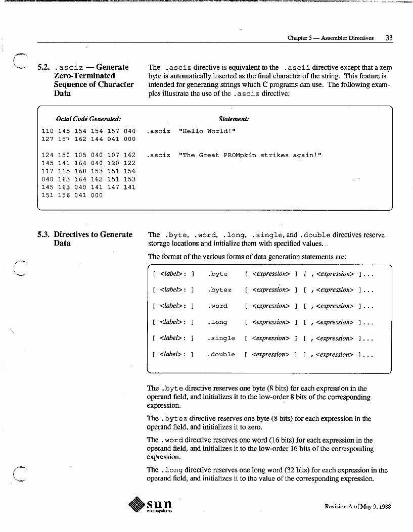
The . asciz directive is equivalent to the . ascii directive except that a zero byte is automatically inserted as the final character of the string. This feature is · intended for generating strings which C programs can use. The following examples illustrate the use of the . asciz directive:
Statement:
.asciz "Hello World!"
.asciz "The Great PROMpkin strikes again!"
The . byte, . word, . long, . single, and . double directives reserve storage locations and initialize them with specified values. __
The format of the various forms of data generation statements are:
<label>: . byte <expression> , <expression> ] ...
<label>: . bytez <expression> , <expression> ] ...
<label>: . word <expression> , <expression> ] ...
<label>: . long <expression> , <expression> ] ...
<label>: .single <expression> , <expression> ] ...
<label>: . double <expression> , <expression> ] ...
The . byte directive reserves one byte (8 bits) for each expression in the operand field, and initializes it to the low-order 8 bits of the corresponding expression.
The . bytez directive reserves one byte (8 bits) for each expression in the operand field, and initializes it to zero.
The . word directive reserves one word (16 bits) for each expression in the operand field, and initializes it to the low-order 16 bits of the corresponding expression.
The .long directive reserves one long word (32 bits) for each expression in the operand field, and initializes it to the value of the corresponding expression.
Revision A of May 9, 1988

34 Assembly Language Reference
5.4. Directives to Switch Location Counter
Space
text
data
bss
The . single directive reserves one long word for each expression in the operand field, and initializes it to the low-order 32 bits of tile corresponding expression.
The . double directive reserves a pair of long words for each expression in the operand field, and initializes them to the value of the corresponding expression.
Multiple expressions can appear in the operand field of the . byte, . word, .long, . single, and . double directives. Multiple expressions must be separated by commas.
Thesestatements .text, .data, .bss, .datal,and .data2,changethe 'control section' where assembled code is loaded.
as (and the system linker) view programs as divided into three distinct sections or address spaces:
Description
The address space where the executable machine instructions are placed.
The address space where initialized data is placed. The assem-bler actually knows about three data areas, namely, data, datal, and data2. The second and third data areas are mainly for the benefit of compilers and are of minimal interest to the assembly language programmer.
If the -R option is coded on the as command line, it means that the initialized data should be considered read-only. It is actually placed at the end of the text area.
The address space where the uninitialized data areas are placed. Also, see the .lcomm directive described below.
For historical reasons, the different areas are frequently referred to as 'control sections' (csects for short).
These sections are equivalent as far as as is concerned, with the exception that no instructions or data are generated for the bss section- only its size is cqmputed and its symbol values are output.
During the first pass of the assembly, as maintains a separate location counter for each section. Consider the following code fragments:
Revision A of May 9, 1988

0 \, .. ,/
5.5 . . skip- Advance the Location Counter
5.6. . 1 comm -Reserve Space in bs s Area
Chapter 5 - Assembler Directives 35
.text place next instruction code: movw dl,d2 in text section
.data now generate data in grab: .long 27 data section
.text now revert to text more: addw d2,dl section
.data now back to data section hold: .byte 4
During the first pass, as creates the intermediate output in two separate chunks: one for the text section and one for the data section. In the text section, code immediately precedes more; in the data section, grab immediately precedes hold. At the end of the first pass, as rearranges all the addresses so that the sections are sent to the output file in the order: text, data and bss.
The resulting output file is an executable image file with all addresses correctly resolved, with the exception of undefined . globl's and . comm's.
For more information on the format of the assembler's output file, consult the a.out(5) entry in the System Programmer's Reference Manual.
The . skip directive reserves storage by advancing the current location counter a specified amount. The format of the . skip directive is:
( [ <label>: ] . skip < size > ]
where <size> is the number of bytes by which the location counter should be advanced. The . skip directive is equivalent to performing direct assignment on the location counter. For instance, a . skip directive like this:
(~T_a_b_l_e ____ ._s_k_i_P ___ l_o_o_o ____________________________________ ~] reserves 1000 bytes of storage, with the value of Table equal to the address of the first byte.
The . 1 comm directive is a compact way to get a specific amount of space reserved in the bss area. The format of the .lcomm directive is:
[~_.l_c_o_mm __ ~,_< __ n_a_~ ___ >_,< __ s_n_e __ > ________________________________ ~] where <name> is the name of the area to reserve, and <size> is the number of bytes to reserve. The .lcomm directive specifically reserves the space in the bss area, regardless of which location counter is currently in effect.
Revision A of May 9, 1988

36 Assembly Language Reference
5.7 .. globl- Designate an External Identifier
5.8. . cornrn -Define Name and Size of a Common Area
A . lcornrn directive like this:
[ .lcomm lower_forty,1200
is equivalent to these directives:
.bss lower_forty: .skip size revert to previous control section
switch to .bss area
A program may be assembled in separate modules, and then linked together to form a single executable unit. See the ld(l) command in the SunOS Reference Manual.
External identifiers are defined in each of these separate modules. An identifier which is defined (given a value) in one module may be referenced in another module by declaring it external in both modules.
There are two forms of external identifiers, namely, those declared with the
)
. globl and those declared with the . cornrn directive. The . cornrn directive is described in the next section.
External symbols are declared with the . globl assembler directive. The format is:
[ .globl <symbol> [ , <symbol> ] . . .
For example, the following statements declare the array TABLE and the routine SRCH as external symbols, and then define them as locations in the current control section:
TABLE: SRCH:
.globl
.word movw
etc.
TABLE, SRCH 0,0,0,0,0 TABLE, dO
)
The . cornrn directive declares the name and size of a common area, for compatibility with FOR1RAN and other languages which use common. The format of the . cornrn statement is:
[ . comm <name>, <constant expression>
where <name> is the name of the common area, and <constantexpression> is the size of the common area. The . cornrn directive implicitly declares the identifier <name> as an external identifier.
)
Revision A of May 9, 1988
C l /

5.9 .. align- Force Location Counter to Particular Byte Boundary
5.10. . even -Force Location Counter to Even Byte Boundary
5.11 •. stabx- Build Special Symbol Table Entry
Chapter 5 -Assembler Directives 37
as does not allocate storage for common symbols; this task is left to the linker. The linker computes the maximum declared size of each common symbol (which may appear in several load modules), allocates storage for it in the final bss section, and resolves linkages. If, however, <name> appears as a global symbol (label) in any module of the program, all references to <name> are linked to it, and no additional space is allocated in the bss area.
The . align directive advances the location counter to the next one-, two- or four-byte boundary, if it is not currently on such a boundary. Intervening bytes are filled with zeros. The format of the . align directive is:
(.align < size > ]
where <size> must be an assembler expression which evaluates to 1, 2 or 4.
This directive is necessary because word and long word data values must lie on even-byte boundaries, because machine instructions must start on even-byte boundaries, and because the MC68020 is much more efficient if word and long word data are on even-byte and four-byte boundaries, respectively.
The . even directive advances the location counter to the next even-byte boundary, if its current value is odd. This directive is necessary because word and long word data values must lie on even-byte boundaries, and also because machine instructions must start on even-byte boundaries. . even is equivalent to. align 2.
( .even l The . s tabx directives are provided for the use of compilers which can generate information for the symbolic debuggers dbxand dbxtool. The directives . stabs, . stabd, and . stabn build various types of symbol table entries.
The . stab directives have the following forms:
• stabs name, type, 0, desc, value
. s t abn type, 0 , desc, value
or
(~ __ .s_t_a_b_d _____ ~_p_e_,_o_,_de_s_c ______________________________________ )
Revision A of May 9, 1988

3 8 Assembly Language Reference
5.12. . proc- Separate Procedures for SpanDependent Instruction Resolution
5.13. . cpid- Name Default Coprocessor ID
The . stabs directives are used to describe types, variables, procedures, and so on, while the . stabn directives convey information about scopes and the mapping from source statements to object code.
A . stabd directive is identical in meaning to a corresponding . stabn directive with the value field set to "."(dot), which the assembler uses to mean the current location. Most of the needed information, for example symbol name and type structure, is contained in the name field. The type field identifies the type of symbolic information, for example source file, global symbol, or source line. The desc field specifies the number of bytes occupied by a variable or type or the nesting level for a scope symbol. The value field specifies an address or an offset
The . proc directive separates procedures for span-dependent instruction resolution. In its absence the assembler does span-dependent instruction resolution over entire files. If . proc is used, the resolution is done between occurrences of the directive and between either end of the file and its nearest occurrences. Since the algorithm used requires more than linear time, using . proc can save significant time for large assemblies. Branch instructions must not cross . proc directives, although calls may.
( .proc
The . cpid directive gives the assembler a coprocessor id value to use for MC68881 instructions that don't have an explicit coprocessor id given. The form of the directive is
( .cpid < id >
If no . cpid directive is given in a program, a value of 1 is assumed. Since no Sun systems currently have more than one coprocessor, you don't need to use this directive.
J
J
sun Revision A of May 9, 1988 micros ysterns
0
.0 \_)

c 6
Instructions and Addressing Modes
Instructions and Addressing Modes............................................................................... 41
6.1. Instruction Mnemonics ................................................................................................. 41
6.2. Extended Branch Instruction Mnemonics ......................................................... 41
6.3. Addressing Modes........................................................................................................... 42
6.4. Addressing Categories .................................................................................................. 46


c
6 Instructions and Addressing Modes
This chapter describes the conventions used in as to specify instruction mnemonics and addressing modes. The information in this chapter is specific to
the machine instructions and addressing modes of the MC68010 and MC68020
microprocessors and the MC68881 coprocessor. See Appendix C for information on the Sun FP A's instructions set and addressing modes.
6.1. Instruction Mnemonics The instruction mnemonics that as uses are based on the mnemonics described in the relevant Motorola processor manuals. However, as deviates from them in several areas.
6.2. Extended Branch Instruction Mnemonics
Most of the MC68010 and MC68020 instructions can apply to byte, word or long
operands. Instead of using a qualifier of . b, . w, or .1 to indicate byte, word, or
long as in the Motorola assembler, as appends a suffix to the normal instruction mnemonic, thereby creating a separate mnemonic to indicate which length operand was intended.
For example, there are three mnemonics for the or instruction: orb, orw, and orl, meaning or byte, or word, and or long, respectively.
Instruction mnemonics for instructions with unusual opcodes may have additional suffixes. Thus in addition to the normal add variations, there also exist addqb, addqw and addql for the add quick instruction:
Branch instructions come in two flavors for the MC68010, byte (or short) and word, and an additional flavor, long, for the MC68020. Append the suffix s to the word mnemonic to specify the short version of the instruction. For example, beq refers to the word version of the Branch if Equal instruction, beqs refers to
the short version, while beql refers to the long version.
In addition to the instructions which explicitly specify the instruction length, as supports extended branch instructions, whose names are, in most cases, constructed from the word versions by replacing the b with j.
If the operand of the extended branch instruction is a simple address in the text segment, and the offset to that address is sufficiently small, as automatically generates the corresponding short branch instruction.
If the offset is too large for a short branch, but small enough for a branch, the corresponding branch instruction is generated. If the operand references an external address or is complex (see next paragraph), the extended branch
41 Revision A of May 9, 1988

42 Assembly Language Reference
6.3. Addressing Modes
instruction is implemented either by a jmp or j s r (for j r a or j b s r ), or (for the MC68010) by a conditional branch (with the sense of the condition inverted) around a jmp for the extended conditional branches and (for the MC68020) the corresponding long branch.
The extended mnemonics should only be used in the text segment......__ if they are used in the data segment, the most general form of the branch is generated.
In this context, a complex address is either an address which specifies other than normal mode addressing, or a relocatable expression containing more than one relocatable symbol. For instance, if a, b and c are symbols in the current segment, the expression a+b-c is relocatable, but not simple.
Consult Appendix B for a complete list of the instruction opcodes.
Table 6-1 below describes the addressing modes that asrecognizes. Note that certain modes are not valid for the MC68010. The notations used in this table have these meanings:
Notation Meaning
an An address register. dn A data register. ri Either a data register or an address register. fi A floating-point register.
d A displacement, which is a constant expression in as. In MC68020 mode, a length specifier (: L, described below) may be appended to the displacement. Any forward or external refer-ences require the length specifier to be : 1. All other references permit either :1 or : w or nulls.
L The index register's length. This may be either long (1) or word (w) or null. If the only value permitted by a particular addressing mode or category is 1 or w, then L will be replaced by the appropriate value in the table notation.
s A scale factor that may be used to multiply the index register's length. The scale factor may have a value of 1, 2, 4, or 8.
The table notation of two or three items separated by colons, such as r i : L : s, indicate items that may be optional. In that particular case, you may not specify : s unless you have specified :L, which you may not specify unless you have specified ri. The items in the list must appear in the order given in the notation of the tables that follow.
In the table where both d and d' are specified, d corresponds to a MC68020 outer displacement and d' corresponds to a MC68020 base displacement.
xxx refers to a constant expression.
Revision A of May 9, 1988

c
(' "'-~
Chapter 6- Instructions and Addressing Modes 43
Certain instructions, particularly move, accept a variety of special registers including:
Name Register
sp the stack pointer, which is equivalent to a 7 sr the status register cc the condition codes of the status register
usp the user mode stack pointer pc the program counter sfc the source function code register dfc the destination function code register
fpcr the floating-point control register fpsr the floating-point status register fpiar the floating-point instruction address register
The memory-indirect and program counter memory-indirect addressing modes listed in the following tables are usable only with the MC68020.
In each of these addressing modes, up to four user-specified values are used to generate the final operand address:
D base register
D base displacement
D index register
D outer dispacement
All four user-specified values are optional. Both base and outer displacements may be null, word or long. When a displacement is null, or an element is suppressed, its value is taken as zero in the effective address calculation.
In the case of memory-indirect addressing, an address register (an) is used as a base register, and its value can be adjusted by an optional base displacement ( d' ).
An index register (ri) specifies an index operand (ri: L: s) and finally, an outer displacement ( d) can be added to the address operand, yielding the effective address.
Program counter memory-indirect mode is exactly the same. The only difference is that the program counter is used as the base register.
Some examples of these addressing modes follow:
Revision A of May 9, 1988

44 Assembly Language Reference
Table 6-1
Mode
Register
Register Deferred
Register List
FP A register
Floating-Point Register
(MC68881 only)
Postincrement
Predecrement
Displacement
Word Index
Long Index
Absolute Short
Absolute Long
PC Displacement
PC Word Index
PC Long Index PC-Memory Indirect
Pre-Indexed (68020)
PC-Memory Indirect
Post-Indexed (68020)
Memory Indirect
Pre-Indexed (68020)
Memory Indirect Post-Indexed (68020)
an@ (d' : L, ri:L:s)@(d:L) an@(d:L)@(d' :L,ri:L:s) an@@ an@(d:L)@ an@(d' :L,ri:L:s)@ pc@@ pc@(d:L)@ pc@(d' :L,ri:L:s)@(d:L) pc@(d:L)@(d' :L,ri:L:s) @(d:L)@ @(d' :L,ri:L:s)@(d:L) @(d:L)@(d' :L,ri:L:s) @(d' :L,ri:L:s)@
In the table below, note that the notation ri/rj means ri and rj, while ri_rj means ri throughrj.
Addressing Modes
Notation Example
an,dn,sp,pc,cc,sr,usp movw a3,d2 an@ movw a3@,d2 ri-rj or ri/rj movem a0-a4, a6@-
fpai fpmoves fpal,d2 fpi fmoves fpl,a3@(24)
an@+ movw a3@+,d2 an@- movw a3@-,d2
an@ (d) movw a3@(24),d2 an@ (d, ri:w) movw a3@(16, d2:w) ,d3 an@ (d, ri: 1) movw a3@(16, d2:1) ,d3
;ax:w movw 14:w,d2 ;ax:1 movw 14:1,d2
pc@ (d) movw pc@(20),d3 pc@ (d,ri:w) movw pc@(14, d2:w),d3 pc@ (d, ri: 1) movw pc@(l4, d2 :1) ,d3 pc@ (d' :L, ri:L: s)@ (d:L) mov1 pc@(2:w,d4:w:4)@(14:1),d3
pc@(d:L)@(d':L,ri:L:s) mov1 pc@(d:1)@(3:w,d2:1:4),d3
an@ (d' :L, ri:L: s)@ (d:L) mov1 al@(d:L,d2:1:4)@(14:w)
an@(d:L)@(d' :L,ri:L:s) mov1 a2@(2:w)@(14:w,d4:w:2)
Revision A of May 9, 1988
0

c Table 6-1
Mode
Normal
Immediate
c
Chapter 6- Instructions and Addressing Modes 45
Addressing Modes- Continued
Notation Example
identifier movw widget,d3
#XXX movw #27+3,d3
Nonnal mode assembles as PC-relative if the assembler can detennine that this is appropriate, otherwise it assembles as either absolute short or absolute long, under control of the -d2 command line option.
The Motorola manuals present different mnemonics (and in fact different fonns of the actual machine instructions) for instructions that use the literal effective address as data instead of using the contents of the effective address. For instance, they use the mnemonic adda for add address. as does not make these distinctions because it can detennine the type of opcode required from the fonn of the operand. Thus an instruction of the fonn:
[avenue: .word 0
~~~1 #avenue,aO l assembles to the add address instruction because as can detennine that aO is an address register.
right_now: - 40000
addl #right_now,dO
assembles to an add immediate instruction because as can detennine that right_now is a constant.
Because of this detennination of operand fonns, some of the mnemonics listed in the Motorola manuals are missing from the set of mnemonics that as recognizes.
Certain classes of instructions accept only subsets of the addressing modes above. For example, the add instruction does not accept a PC-relative address as a destination, and register lists may be used only with the movem and fmovem
instructions.
as tries to check all these restrictions and generates the illegal operand error code for instructions that do not satisfy the address mode restrictions.
The next section describes how the address modes are grouped into addressing categories.
Revision A of May 9, 1988

46 Assembly Language Reference
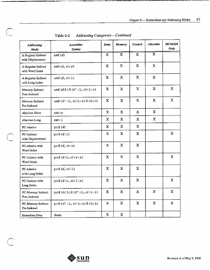
6.4. Addressing Categories The processors group the effective address modes into categories derived from the manner in which they are used to address operands. Note the distinction between address modes and address categories. There are 14 addressing modes in the MC68010 and 18 in the MC68020, and they fall into one or more of four addressing categories. The addressing categories are defined here, followed by a table summarizing the grouping of the addressing modes into categories. Note that register lists can be used only by the movem and fmovem instructions.
Addressing
Mode
Register Direct
A-Register Indirect
A-Register Indirect
with Displacement
A-Register Indirect with Word Index
A-Register Indirect with Long Index
A-Register Indirect with Post Increment
A-Register Indirect
with Pre Decrement
Category Meaning
Data means that the effective address mode is used to refer to data operands such as a d register or immediate data.
Memory means that the effective address mode can refer to memory operands. Examples include all the a-register indirect address modes and all the absolute address modes.
Alterable means that the effective address mode refers to operands which are writeable (alterable). This category takes in every addressing· mode except the PC-relative addressing modes and the immedi-ate address mode.
Control means that the effective address mode refers to memory operands with no explicit size specification.
Some addressing categones can be intersected to make more restrictive ones. For example, the Motorola MC68010 manual mentions the Data Alterable Addressing Mode to mean that the particular instruction can only use those modes which provided data addressing and are alterable as well.
Table 6-2 Addressing Categories
Assembler Data Memory Control Alterable MC68020 Syntax Only
an, dn, sp, pc, cc, sr, usp X X
an@ X X X X
an@ (d: L) X X X X X
an@ ( d: L, ri : w: s) X X X X X
an@ (d:L,ri:l:s) X X X X X
an@+ X X X
an@- X X X
sun microsystems
Revision A of May 9, 1988
..
Chapter 6- Instructions and Addressing Modes 47
Table 6-2 Addressing Categories- Continued
Addressing Assembler Data Memory Control Alterable MC68020
Mode Syntax Only
A-Register Indirect an@ (d) X X X X
with Displacement
A-Register Indirect an@ (d, ri: w) X X X X
with Word Index
A-Register Indirect an@ (d, ri: 1) X X X X
with Long Index
Memory-Indirect an@ (d:L)@ (d': L, ri:L: s) X X X X X
Post-Indexed
Memory-Indirect an@ ( d' : L, ri: L : s) @ ( d: L) X X X X X
Pre-Indexed
Absolute Short xxx::w X X X X
Absolute Long xxx::1 X X X X
PC-relative pc@ (d) X X X
PC-Indirect pc@(d:L) X X X X
with Displacement
PC-relative with pc@ (d, ri: w) X X X Word Index
PC-Indirect with pc@ (d:L,ri:w:s) X X X X Word Index
PC-relative pc@ (d, ri: 1) X X X with Long Index
PC-Indirect with pc@ (d: L, ri: 1: s) X X X X Long Index
PC-Memory Indirect pc@(d:L)@(d' :L,ri:L:s) X X X X X Post-Indexed
PC-Memory Indirect pc@(d' :L,ri:L:s)@(d:L) X X X X X Pre-Indexed
Immediate Data #nnn_ X X
Revision A of May 9, 1988


A as Error Codes
as Error Codes .............................................................................................................................. 51
A.1. Usage Errors ........................ :............................................................................................. 51
A.2. Assembler Error Messages........................................................................................ 51
c

(\ \._ .. /

c
C\ '
A.l. Usage Errors
A.2. Assembler Error Messages
A as Error Codes
Cannot open output file The specified output file cannot be created. Check that the pennissions allow opening this file.
Cannot open source file The assembler cannot open the specified source file. Check the spelling, that the pathname supplied is correct, and that you have read pennission for the
file.
No input file One or more input files must be specified- as cannot accept the output of a pipe as its input.
Too many file names given The assembler cannot cope with more than one source file. Break the job into smaller stages.
Unknown option 'x' ignored as does not recognize the option x. Valid options are listed in Section 1.1 of this manual.
If as detects any errors during the assembly process, it prints out a message of the fonn:
[as: error (<line_no>) : <error _code>
Error messages are sent to standard error. Here is a list of as error codes, and their possible causes.
Illegal .align
J
The expression following a . align evaluates to some value other than 1, 2 or4.
51 Revision A of May 9, 1988

52 Assembly Language Reference
Invalid assignment An attempt was made to redefine a label with a direct assignment statement.
Invalid Character An unexpected character was encountered in the program text.
Invalid Constant An invalid digit was encountered in a number. For example, using an 8 or 9 in an octal number. Also happens when an out-of-range constant operand is found in an instruction - for example:
[
addq #200,d0 ]
~---a_s_l_l __ #_1_2_,_ct_o ____________________________________ ~
Invalid opcode The assembler did not recognize an instruction mnemonic. Probably a misspelling.
Invalid operand The operand used is not consistent with the instruction used - for example: r--,
[ ',
[~ __ a_d_d_q_b __ n_,_a_s ___________________ __,] \_. j
is an invalid combination of instruction and operand. Check the instruction set descriptions for valid combinations of instructions and operands.
Invalid Operator Check the operand field for a bad operator. The operators that as recognizes are plus (+),minus (-),negate or one's complement C), multiply ( * ), and divide (I).
Invalid register expression A register name was found where one should not appear- for example:
(.___a_d_d_l __ *ct_o_, __ t_h_e_r_e ___________________ __,}
Invalid Register List The register list in a movem or fmovem instruction is malformed. Note that the list must contain more than one register name: to express a list containing just a single register, you must write its name twice separated by a slash, e.g. fpO/fpO."
Revision A of May 9, 1988

Appendix A- as Error Codes 53
Invalid string An invalid string was encountered in an . ascii or . asciz directive.
o Make sure the string is enclosed in double quotes.
o Remember that you must use the sequence\" to represent a quote inside a string.
Invalid symbol An operand that should be a symbol is not - for example:
( .globl 3
because the constant 3 is not a symbol.
Invalid Term The expression evaluator could not find a valid term: a symbol, constant or
<expression>. An invalid prefix to a number or a bad symbol name in an operand gen
erates this message.
Line too long
J
A statement was found which has more than 4096 characters before the newline character.
Missing close-paren ')' An unmatched'(' was found in an expression.
Multiply defined symbol
o An identifier appears twice as a label.
o An attempt to redefine a label using a direct assignment statement.
o An attempt to use, as a label, an identifier which was previously defined in a direct assignment statement.
Multiply Defined Symbol (Phase Error) This rarely occurring message indicates an inconsistency in the assembler. Report it to Sun Microsystems Customer Support if it occurs.
N on-relocatable expression If an expression contains a relocatable symbol (a label, for instance), the only operations that can be applied to it are the addition of absolute expressions or the subtraction of another relocatable symbol (which produces an absolute result).
Revision A of May 9, 1988

54 Assembly Language Reference
Odd address The previous instruction or pseudo-op required an odd number of bytes and this instruction requires word alignment. This error can only follow an . ascii, an . asciz, a . byte, or a . skip pseudo-operation.
NOTE Use a . even directive to ensure that the location counter is forced to a 16-bit boundary.
Offset too large The instruction is a relative addressing instruction and the displacement between this instruction and the label specified is too large for the address field of the instruction.
Out of strings space No more room is left in the assembler's internal string table. Divide the program into smaller portions; assemble portions of the program separately, then bind them together using the linker.
Register out of range In the FP A's dot product, matrix move and transpose instructions when the register specified does not fall within the specified range, then this error is reported. Note that for most instructions where one operand is an effective address, the register range is 0 to 15. If all operands are FPA registers, the ('/\ register range is 0 to 31. For constant RAM registers, the range is 0 to 511. '-This type of error would probably also cause the Invalid operand error to be reported.
Stab storage exceeded No more room is left in the assembler's symbol table for debug information. Cut the program into smaller portions; assemble portions of the program separately, then bind them together using the linker.
Symbol storage exceeded No more room is left in the assembler's symbol table. Divide the program into smaller portions; assemble portions of the program separately, then bind them together using the linker.
Symbol Too Long A local label reference longer than one digit was found.
sun microsystems
Revision A of May 9, 1988
0

c
Appendix A- as Error Codes 55
Undefined L-symbol This is a warning message. A symbol beginning with the letter 'L' was used but not defined. It is treated as an external symbol. Compiler-generated labels usually start with the letter 'L' and should be defined in this assembly. The absence of such a definition usually indicates a compiler code generation error. This message is also generated by the use of symbols such as n$ if n$ has not been defined.
Unqualified forward reference The displacement\field in an MC68020 based/indexed address mode contains an unqualified forward reference. Note that the displacement in a based/indexed address mode for the MC68020 instruction set can contain a forward or external reference only if the length specifier is present. The length specifier should be : 1 (long). This type of error would probably also cause Multiply defined symbol (Phase error).
Undefined Symbol A label reference to an undefined local label was found.
Wrong number of operands Check Appendix B for the correct number of operands for the current instruction.
Revision A of May 9, 1988


c B
List of as Opcodes
List of as Opcodes ................................................................................................................... 59
c

0

B List of as Ope odes
This appendix is a list of the instruction mnemonics accepted by as, grouped alphabetically. The list is divided into two tables, the first covers the MC680x0 processor's instructions, the second covers the MC68881 floating-point processor's instructions. For more information about floating-point programming, see the Floating-Point Programmer's Guide.
Each entry describes the following things:
o The mnemonics for the instruction,
o The generic name of the instruction,
o The assembly language syntax and the variations on the instruction,
o Whether the instruction is specific to the MC68020, or has extended capabil-ities on the MC68020 compared to the MC68010.
The syntax for as machine instructions differs somewhat from the instruction layouts and categories shown in the Motorola processor manuals. For example, as provides a single set of mnemonics for add (add binary), adda (add address), and addi (add immediate), differentiated only by the length of the operands. In general, as selects the appropriate instruction from the form of the operands.
Here is a brief explanation of the notations used below.
o An instruction of the form addx in the assembly language syntax column means that the instruction is coded as addb, addw, addl, etc.
o An operand field of an means any A-register.
o An operand field of dn means any D-register.
o An operand field of rn means any A- or D-register.
o An operand field of fn means any floating-point register.
o An operand field of en means any control register.
o An operand field of ea means an effective address designated by one of the permissible addressing modes. Consult the relevant Motorola processor manual for details of the allowed addressing modes for each instruction.
59 Revision A of May 9, 1988

60 Assembly Language Reference
Mnemonic abed
addb
addw
addl
addqb
addqw
addql
addxb
addxw
addxl
an db
andw
andl
aslb
aslw
asll
NOTE
Table B-1
o An operand field of vector means an exception vector location.
o An operand field of #data means an immediate operand.
o Other special registers such as cc (condition code register) and sr (status register) are specifically indicated where appropriate.
The MC68020 provides a set of bit-field manipulating instructions that don't exist on the MC68010. Their notation includes a bit field specifier of the form { offset:width}, where the offset denotes the beginning of the bit field in the word and the width is the number of bits in the field.
Offset values are counted from the high-order bit, as 0, to the low-order bit, as 31.
This ordering is the reverse of the convention used in the bchg, bclr, bset, andbtst instructions.
Offset and width may be either constants or data registers. For example:
o bfins dO,a5@(4){#0:#9}
o bfexta a5@(4){d0:#8},d7
In the table that follows, the processor is assumed to be the MC68010 unless specifically stated otherwise.
List of MC680x0 Instruction Codes
Operation Name Syntax Processor add decimal with extend abed dy,dx
abed ay@-, aX@-
add binary adc!X ea,dn
adc!X dn,ea
adc!X ea,an (except addb)
adc!X #data,ea
add quick addqX #data,ea
add extended addxX dy, ciX addxX ay@-, aX@-
logical and anc!X ea,dn anc!X dn,ea anc!X #data, dn
arithmetic shift left aslX c!X, dy
aslX #data, dy
aslX ea
Revision A of May 9, 1988

Appendix B -List of as Opcodes 61
Table B-1 List of MC680x0 Instruction Codes- Continued
Mnemonic Operation Name Syntax Processor asrb arithmetic shift right asrX dX,dy
asrw asrX #data,dy
asrl asrX ea
bee branch conditionally be eX label
bccl MC68020
bees
bchg test a bit and change bchg dn,ea
bchg #data, ea
bclr test a bit and clear bclr dn,ea
bclr #data, ea
bkpt breakpoint bkpt #data MC68020 c
bset test a bit and set bset dn,ea
bset #data,ea
btst test a bit btst dn,ea
btst #data, ea
bfchg test a bit field and change bfchg ea{ offset:width) MC68020
bfclr test a bit field and clear bfclr ea{ offset:width) MC68020
bfexts extract a bit field signed bfexts ea{offset.width), dn MC68020
bfextu extract a bit field unsigned bfextu ea{offset.width), dn MC68020
bfffo find first one in bit field bfffo ea{offset:width), dn MC68020
bfins insert a bit field bfins dn, ea{offset.width) MC68020
bfset test a bit field and set bfset ea{ offset:width) MC68020
bftst test a bit field bftst ea{ offset:width) MC68020
bcs branch carry set bcsX ea
bcsl MC68020
bess
beq branch on equal beqX ea
beql MC68020
beqs
bge branch greater or equal bgeX ea
bgel MC68020
bges
bgt branch greater than bgtX ea
bgtl MC68020
c bgts
~~sun ~ microsystems Revision A of May 9, 1988

62 Assembly Language Reference
Table B-1 List of MC680x0 Instruction Codes- Continued
Mnemonic Operation Name Syntax Processor bhi branch higher bhiX ea bhil , MC68020 bhis
ble branch less than or equal bleX ea blel MC68020 bles
bls branch lower or same blsX ea blsl MC68020
blt branch less than bltX ea
bltl
blts
bmi branch minus bmiX ea bmil
bmis
bne branch not equal bneX ea bnel MC68020 bnes
bpl branch positive bplX ea bpll MC68020 bpls
bra branch always braX label bral MC68020 bras
bsr subroutine branch bsrX label bsrl MC68020 bsrs
bvc branch overflow clear bvcX ea bvcl MC68020 bvcs
bvs branch overflow set bvsX ea bvsl bvsl MC68020 bvss
callm call module callm ,g,data, ea MC68020
cas2b compare & swap with operand cas2X clcl: clc2, dul: du2, {rnl) : { rn2) MC68020 cas21 MC68020 cas2w MC68020
casb compare & swap with operand casX de, du, ea MC68020 casl MC68020 casw MC68020 0
sun microsystems
Revision A of May 9, 1988

Appendix B -List of as Opcodes 63
Table B-1 List of MC680x0 Instruction Codes- Continued
Mnemonic Operation Name Syntax Processor
chkb check register against bounds chkX ea,dn MC68020 "
chkw MC68020
chkl MC68020
chk2b check register against bounds chk2X ea, rn MC68020
chk21 MC68020
chk2w MC68020
clrb clear an operand clrX ea
clrw
clrl
cmp2b compare register against bounds cmp2X ea,rn MC68020
cmp21 MC68020
cmp2w MC68020
cmpmb compare memory cmpmX ay@+,aX@+
cmpmw
cmpml
cmpb arithmetic compare cmpX ea,dn
cmpw cmpX tdata, ea
cmpl
dbcc decrement & branch on carry clear dbcc dn, label
dbcs " on carry set dbcs dn, label
dbeq " on equal dbeq dn, label
dbf " on false dbf dn, label
dbge " on greater than or equal dbge dn, label
dbgt " on greater than dbgt dn, label
dbhi " on high db hi dn, label
dble " on less than or equal dble dn, label
dbls " on low or same dbls dn, label
dblt " on less than dblt dn, label
dbmi " on minus dbmi dn, label
dbne " on not equal dbne dn, label
dbpl " on plus dbpl dn, label
dbra " always (same as dbf) dbra dn, label
dbt " on True dbt dn, label
dbvc " on overflow clear dbvc dn, label
dbvs " on overflow set dbvs dn, label
divs signed divide divs ea,dn
divsl divsX ea,dn MC68020
divsll divsX ea,dq MC68020
divsX ea,dr:dq MC68020
divu unsigned divide divu ea,dn
divul divuX ea,dn MC68020
Revision A of May 9, 1988

64 Assembly Language Reference
Table B-1 List of MC680x0 Instruction Codes- Continued
Mnemonic Operation Name Syntax Processor divuw divuX ea,cln MC68020
divuX ea,dq MC68020 divuX ea, dr: dq MC68020
divull divull ea,dr:dq MC68020
eorb logical exclusive or eorX cln, ea eorw eorX #data, ea eorl eorb #data, cc
eorw #data,sr
exg exchange registers exg rx,ry
extbl sign extend extbl dn MC68020 extw extX cln extl
jmp ~ jump jmp ea jsr jump to subroutine jsr ea jcc jump carry clear jcc ea jcs jump on carry jcs ea jeq jump on equal jeq ea jge jump greater or equal jge ea jgt jump greater than jgt ea jhi jump higher jhi ea jle jump less than or equal jle ea jls jump lower or same jls ea jlt jump less than jlt ea jmi jump minus jmi ea jne jump not equal jne ea jpl jump positive jpl ea jra jump always jra ea jbsr jump to subroutine jbsr ea jvc jump no overflow jvc ea jvs jump on overflow jvs ea
lea load effective address lea ea,an
link link and allocate link an, #disp linkl linkl an, #disp MC68020
lslb logical shift left lslX dx,dy lslw lslX #data,dy lsll lslX ea
lsrb logical shift right lsrX dx,dy lsrw lsrX #data,dy lsrl lsrX ea
movb move data movX ea,ea movl
movw movX #data, cln
Revision A of May 9, 1988

Appendix B -List of as Opcodes 65
c Table B-1 List ofMC680xO Instruction Codes- Continued
Mnemonic Operation Name Syntax Processor
movw move from condition code register movw cc,ea
movw move from status register movw sr,ea
move move to/from control register move rn,cr
move cr, rn
moveml move multiple registers movemX #mask,ea
movemw movemX ea, #mask
movemX ea,reglist
movemX reglist, ea
movepl move peripheral movepX dn, an@ (d)
movepw movepX an@(d),dn
moveq move quick moveq #data, dn
movsb move to/from address space movsX rn,ea
movsw movsX ea,rn
movsl
muls signed multiply muls ea,dn
mulslw mulsX ea, dl MC68020
mulsll mulsX ea, dh:dl MC68020
mulu unsigned multiply mulu ea,dn
mulul muluX ea, dl MC68020
muluX ea, dh:dl MC68020
nbcd negate decimal with extend nbcd ea
negb negate binary negX ea
negw
negl
negxb negate binary with extend negxX ea
negxw
negxl
nap no operation nap
notb logical complement notX ea
notw
notl
orb inclusive or orX ea,dn
orw orX dn,ea
orl or #data,ea
orb #data, cc
orw #data,sr
pack pack pack aX@-,ay@-,#data MC68020
C' ~
pack dX, dy, #data MC68020
pea push effective address pea ea
Revision A of May 9, 1988

66 Assembly Language Reference
Table B-1 List of MC680x0 Instruction Codes- Continued
Mnemonic Operation Name Syntax Processor reset reset device reset
rolb rotate left rolX dx,dy rolw rotate left rolX #data, dy roll rolX ea
rorb rotate right rorX dx,dy rorw rorX #data,dy rorl rorX ea
roxlb rotate left with extend roxlX dx,dy roxlw roxlX #data, dy roxll roxlX ea
roxrb rotate right with extend roxrX dx,dy roxrw roxrX #data, dy roxrl roxrX ea
rtd return and deallocate parameters rtd #data rte return from exception rte rtm return from module rtm rn MC68020 rtr return and restore codes rtr rts return from subroutine rts
rts #n 0 sbcd subtract decimal with extend sbcd dy,dx
sbcd ay@-, aX@-
stop halt machine stop #xxx
subb arithmetic subtract subX ea,dn subw subX dn,ea
subX ea,an .subl subX #data,ea
st set all ones st ea sf set all zeros sf ea shi set high shi ea sls set lower or same sls ea sec set carry clear sec ea scs set carry set scs ea sne set not equal sne ea seq set equal seq ea svc set no overflow svc ea svs set on overflow svs ea spl set plus spl ea smi set minus smi ea sge set greater or equal sge ea slt set less than slt ea sgt set greater than sgt ea sle set less than or equal sle ea
Revision A of May 9, 1988

c Mnemonic
subqb
subqw
subql
subxb
subxw
subxl
swap
tas
trap
trapcc
trapccl
trapccw
trapcs
trapcsl
trapcsw
trapeq
trapeql
trapeqw
trapf
trapfl
trapfw
trapge
trapgel
trapgew
trapgt
trapgtl
trapgt
Appendix B -List of as Opcodes 67
Table B-1 List of MC680x0 Instruction Codes- Continued
Operation Name Syntax Processor
subtract quick subqX #data,ea
subtract quick
subtract extended subxX dy,dx
subxX ay@-, aX@-
swap register halves swap dn
test operand then set tas ea
trap trap #vector
trap on carry clear trapccX MC68020
trapccX #data MC68020
MC68020
trap on carry set trapcsx MC68020
trapcsX #data MC68020
MC68020
trap on equal trapeqX MC68020
trapeqX #data MC68020
MC68020
trap on never true trapfX MC68020
trapfX #data MC68020
MC68020
trap on greater or equal trapgeX MC68020
trapgeX #data MC68020
MC68020
trap on greater trapgtX MC68020
trapgtX #data MC68020
The following table describes the MC68881 instruction mnemonics supported by
as. Each mnemonic indicates the data type that it operates on by the last character of
the mnemonic:
o b indicates a byte format instruction
o w indicates a word format instruction
o 1 indicates a long format instruction
o s indicates a single-precision format instruction
0 d indicates a double-precision format instruction
Revision A of May 9, 1988

68 Assembly Language Reference
o x indicates an extended-precision format instruction
o p indicates a packed format instruction
o y indicates that any of 1, s, p, w, d, orb, are acceptable.
Table B-2 MC68881 Instructions supported by as
Mnemonic Operation Name Syntax fabsx absolute value fabsx ea, fn fabsl fabsx fm, fn fabss fabsy ea, fn fabsp
fabsw
fabsd
fabsb
facosx arc cosine facosx ea, fn facosl facosx fm, fn facoss facosy ea, fn facosp
facosw
facosd
facosb
faddx add faddx ea, fn faddl faddx fm,fn £adds faddy ea,fn faddp
faddw
faddd
faddb
fasinx arc sin fasinx ea, fn fasinl fasinx fm, fn fa sins fasiny ea, fn fasinp
fasinw
fa sind
fasinb
fatanx arc tangent fatanx ea, fn fatanl fatanx fm, fn fa tans fatany ea, fn fatanp
fatanw
fatand
fatanb
fatanhx hyperbolic arc tangent fatanhx ea, fn fatanhl fatanhx fm, fn fatanhs fatanhy ea, fn
(\, I ' \.___/
Revision A of May 9, 1988

Appendix B -List of as Opcodes 69
Table B-2 MC68881 Instructions supported by as- Continued
Mnemonic Operation Name Syntax
fatanhp hyperbolic arc tangent ( contd.)
fatanhw
fatanhd
fatanhb
fbcc branch conditionally fbcc label
fbeq (equal)
fbeql
fbf (false)
fbfl
fbgt (greater than)
fbgtl
fble (less than or equal)
fblel
fblt (less than)
fbltl
fbge (greater than or equal)
fbgel
fbgl (greater than or less)
fbgll
fbgle (greater less or equal)
fbglel
fbgt (greater than)
fbne (not equal)
fbnel
fbneq (not (equal))
fbneql
fbnge (not greater than or equal)
fbngel
fbngl (not greater than or less)
fbngll
fbngle (not greater than, less or equal)
fbnglel
fbngt (not greater than)
fbngtl
fbnle (not less than or equal)
fbnlel
fbnlt (not less than)
fbnltl
fbt (true)
fbtl
fbor (ordered)
fborl c\ fboge (ordered greater or equal)
fbogel
fbogl (ordered greater or less)
Revision A of May 9, 1988

70 Assembly Language Reference
Table B-2 MC688811nstructions supported by as- Continued
Mnemonic Operation Name Syntax
fbogll
fbogt (ordered greater than) fbogtl
fbole (ordered less or equal) fbolel
fbolt (ordered less than) fboltl
fbseq (signalling equal) fbseql
fbsf (signalling false) fbsfl
fbsne (signalling not equal) fbsnel
fbst (signalling true) fbstl
fbueq (unordered equal) fbueql
fbuge (unordered greater or equal)
fbugel
fbugt (unordered greater than) fbugtl
fbule (unordered less or equal) fbulel
fbult (unordered less than) fbultl
fbun (unordered)
fbunl
fcmpx compare fcmpx ea, fn
fcmpl fcmpx fm, fn
fcmps fcmpy ea, fn
fcmpp
fcmpw
fcmpd
fcmpb
fcosx cosine fcosx ea, fn
fcosl fcosx fm, fn fcoss fcosy ea,fn
fcosp
fcosw fcosd,
fcosb
fcoshx hyperbolic cosine fcoshx ea,fn
fcoshl fcoshx fm, fn 0 fcoshs fcoshy ea, fn
Revision A of May 9, 1988

Appendix B -List of as Opcodes 71
Table B-2 MC68881 Instructions supported by as- Continued
Mnemonic Operation Name Syntax
fcoshp
fcoshw hyperbolic cosine (contd.)
fcoshd
fcoshb
fdbcc decrement & branch on condition fdbcc dn, label
fdbeq (equal)
fdbne (not equal)
fdbgt (greater than)
fdbngt (n9t greater than)
fdbge (greater or equal)
fdbnge (not greater or equal)
fdblt (less than)
fdbnlt (not less than)
fdble (less or equal)
fdbnle (not less or equal)
fdbgl (greater or less)
fdbngl (not greater or less)
fdbgle (greater, less or equal)
c fdbngle (not greater, less or equal)
fdbogt (ordered greater than)
fdbule (unordered less or equal)
fdboge (unordered greater or equal)
fdbult (unordered less than)
fdbolt (ordered less than)
fdbuge (unordered greater or equal)
fdbole (ordered less or equal)
fdbugt (unordered greater than)
fdbogl (ordered greater or less)
fdbueq (unordered equal) /
fdbor (ordered)
fdbun (unordered)
fdbf (false)
fdbt (true)
fdbsf (signalling false)
fdbst (signalling true)
fdbseq (signalling equal)
fdbsne (signalling not equal)
fdivx divide fdivx ea, fn
fdivl fdivx fm, fn fdivs fdivy ea, fn fdivp
fdivw
fdivd
fdivb
sun microsystems
Revision A of May 9, 1988

72 Assembly Language Reference
Table B-2 MC68881 Instructions supported by as- Continued
Mnemonic Operation Name Syntax
fetoxx X fetoxx ea, fn ,e
fetoxl fetoxx fm, fn
fetoxs ~ fetoxy ea, fn
fetoxp
fetoxw
fetoxd
fetoxb
fetoxmlx ex -1 fetoxmlx ea, fn
fetoxmll fetoxmlx fm, fn
fetoxmls fetoxmly ea, fn
fetoxmlp
fetoxmlw -fetoxmld
fetoxmlb
fgetexpx get exponent fgetexpx ea, fn
fgetexpl fgetexpx fm, fn
fgetexps fgetexpy ea, fn
fgetexpp
fgetexpw
fgetexpd 0 fgetexpb
fgetmanx get mantissa fgetmanx ea, fn
fgetmanl fgetmanx fm, fn
fgetmans fgetmany ea, fn
fgetmanp
fgetmanw
fgetmand
fgetmanb
fintx integer part fintx ea, fn
fintl fintx fm, fn
fints finty ea,fn
fintp
fintw
fintd
fintb
fintrx integer part, round toward 0 fintrx ea, fn
fintrzl fintrx fm, fn
fintrzs fintry ea,fn
fintrzp '
fintrzw
fintrzd
fintrzb
sun microsystems
Revision A of May 9, 1988

Appendix B -List of as Opcodes 73
Table B-2 MC68881 Instructions supported by as- Continued
Mnemonic Operation Name Syntax
fjcc jump on condition fjcc label
fjeq (equal)
fjne (not equal)
fjneq (not equal or equal)
fjgt (greater than)
fjngt (not greater than)
fjge (greater or equal)
fjnge (not greater or equal)
fjlt (less than)
fjnlt (not less than)
fjle Oess or equal)
fjnle (not less or equal)
fjgl (greater or less)
fjngl (not greater or less)
fjgle (greater, less or equal)
fjngle - (not greater, less or equal) ~
fjogt (ordered greater than)
fjule (unordered less or equal)
fjoge (ordered greater or equal)
fjult (unordered less than)
fjolt (ordered less than)
fjuge (unordered greater or equal)
fjole (ordered less or equal)
fjugt (unordered greater than)
fjogl (ordered greater or less)
fjueq (unordered equal)
fjor (ordered)
fjun (unordered)
fjf (false)
fjt (true)
fjsf (signalling false)
fjst (signalling true)
fjseq (signalling equal)
fjsne (signalling not equal)
floglOx loglO floglOx ea, fn
floglOl floglOx fm, fn
floglOs floglOy fn
floglOp
floglOw
floglOd
flog lOb
.c flog2x log2 flog2x ea, fn flog21 flog2x fm, fn
flog2s flog2y ea, fn
flog2p
Revision A of May 9, 1988

74 Assembly Language Reference
Table B-2 MC68881 Instructions supported by as- Continued
Mnemonic Operation Name Syntax
flog2w log2 ( contd.)
flog2d
flog2b
flognx loge flognx ea, fn
flognl flognx fm, fn
flogns flogny ea, fn
flognp
flognw
flognd
flognb
flognplx loge(x+l) flognplx ea, fn
flognpll flognplx fm, fn
flognpls flognply ea, fn
flognplp
flognplw
flognpld
flognplb
fmodx modulo fmodx ea, fn
fmodl fmodx fm,fn
fmods fmody ea,fn 0 fmodp
fmodw
fmodd
fmodb
fmovex move fp register fmovex ea,fn
fmovel fmovex fm, ea
fmoves fmovey ea, fn
fmovep
fmovew
fmoved
fmoveb
fmovecrx move constant ROM fmovecrx #ccc, fn
fmovemx move multiple data registers fmovemy ea, list
fmoveml fmovemx list, ea
fmovem fmoveml ea, dn
fmovem dn, ea
fmulx multiply fmulx ea, fn
fmull fmulx fm, fn
fmuls ~ fmuly ea, fn
fmulp
- 0 ~~sun ~"' microsystems
Revision A of May 9, 1988

c Table B-2
Mnemonic
fmulw
fmuld
fmulb
fnegx
fnegl
fnegs
fnegp
fnegw
fnegd
fnegb
fnop
fremx
freml
frems
fremp
fremw
fremd
fremb
C' £restore
fsave
fscalex
fscalel
fscales
fscalep
fscalew
fscaled
fscaleb
£sec
fseq
fsne
fsneq
fsgt
fsngt
fsge
fsnge
fslt
fsnlt
fsle
fsnle
fsgl
fsngl
fsgle
Appendix B -List of as Opcodes 75
MC6888llnstructions supported by as- Continued
Operation Name
multiply (contd.)
negate
no operation
IEEE remainder
restore internal state
-save internal state
scale exponent
set according to condition
(equal.)
(not equal)
(not equal or equal)
(greater than)
(not greater than)
(greater or equal)
(not greater or equal)
(less than)
(not less than)
(less or equal)
(not less or equal)
(greater or less)
(not greater or less)
(greater, less or equal)
Syntax
fnegx ea, fn
fnegx fm, fn
fnegy ea, fn
fnop
fremx ea, fn
fremx fm, fn
fremy ea, fn
£restore ea
fsave ea
fscalex ea, fn
fscalex fm, fn
fscaley ea, fn
fscc ea
Revision A of May 9, 1988

76 Assembly Language Reference
Table B-2 MC68881lnstructions supported by as- Continued
Mnemonic Operation Name Syntax
fsngle (greater, less or equal)
fsogt (not greater, less or equal)
fsule (unordered less or equal)
fsoge (ordered greater or equal)
fsult (unordered less than)
fsolt (ordered less than)
fsuge (unordered greater or equal)
fsole (ordered less or equal)
fsugt (unordered greater than)
fsogl (ordered greater or less)
fsueq (unordered equal)
fsor (ordered)
fsun (unordered)
fsf (false)
fst (true)
fssf (signalling false)
fsst (signalling true)
fsseq (signalling equal)
fssne (signalling not equal)
fsgldivx single-precision divide fsgldi vx ea, fn
fsgldivs fsgldivx fm, fn 0 fsgldivl fsgldivy ea, fn
fsgldivp
fsgldivw
fsgldivb
fsglmulx single-precision multiply fsglmulx ea, fn
fsglmuls fsglmulx fm, fn
fsglmull fsglmuly ea, fn
fsglmulp
fsglmulw
fsglmulb
fsinx sin fsinx ea, fn
fsinl fsinx fm, fn
fsins fsiny ea, fn
fsinp
fsinw
fsind
fsinb
fsincosx simultaneous sine and cosine fsincosx ea,fc:fs
fsincosl ' fsincosx fm, fc: fs
fsincoss fsincosy ea, fc: fs
fsincosp 0 Revision A of May 9, 1988

Appendix B -List of as Opcodes 77
Table B-2 MC68881 Instructions supported by as- Continued
Mnemonic Operation Name Syntax
fsincosw simultaneous sine and cosine ( contd.)
fsincosd
fsincosb
fsinhx hyperbolic sine fsinhx ea, fn
fsinhs fsinhx fm, fn
fsinhp fsinhy ea, fn
fsinhw
fsinhd
fsinhb
fsqrtx square root fsqrtx ea, fn
fsqrtl fsqrtx fm, fn
fsqrts fsqrty ea, fn
fsqrtp
fsqrtw
fsqrtd
fsqrtb
fsubx subtract fsubx ea, fn
fsubl fsubx fm, fn
fsubs fsuby ea, fn
fsubp
fsubw
fsubd
fsubb
ftanx tangent ftanx ea, fn
ftanl ftanx fm,fn
ftans ftany ea, fn
ftanp
ftanw
ftand
ftanb
ftanhx hyperbolic tangent ftanhx ea, fn
ftanhl ftanhx fm, fn
ftanhs ftanhy ea, fn
ftanhp
ftanhw
ftanhd
ftanhb
ftentoxx lOX ftentoxx ea, fn
ftentoxl ftentoxx fm, fn
ftentoxs ftentoxy ea, fn c ftentoxp
Revision A of May 9, 1988
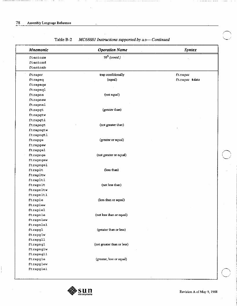
78 Assembly Language Reference
Table B-2 MC68881 Instructions supported by as- Continued
Mnemonic Operation Name Syntax
ftentoxw lOx ( contd.)
ftentoxd
ftentoxb
ftrapcc trap conditionally ftrapcc
ftrapeq (equal) ftrapcc idata
ftrapeqw
ftrapeql
ftrapne (not equal)
ftrapnew
ftrapnel
ftrapgt (greater than)
ftrapgtw
ftrapgtl
ftrapngt (not greater than)
ftrapngtw
ftrapngtl
ftrapge (greater or equal)
ftrapgew
ftrapgel
ftrapnge (not greater or equal)
ftrapngew
ftrapngel
ftraplt (less than)
ftrapltw
ftrapltl
ftrapnlt (not less than)
ftrapnltw
ftrapnltl
ftraple (less than or equal)
ftraplew
ftraplel
ftrapnle (not less than or equal)
ftrapnlew
ftrapnlel
ftrapgl (greater than or less)
ftrapglw
ftrapgll
ftrapngl (not greater than or less)
ftrapnglw
ftrapngll
ftrapgle (greater, less or equal)
ftrapglew
ftrapglel
0 Revision A of May 9, 1988

c
c
c
Mnemonic
ftrapngle
ftrapnglew
ftrapnglel
ftrapogt
ftrapogtw
ftrapogtl
ftrapule
ftrapulew
ftrapulel
ftrapoge
ftrapogew
ftrapogel
ftrapult
ftrapultw
ftrapultl
ftrapolt
ftrapoltw
ftrapoltl
ftrapuge
ftrapugew
ftrapugel
ftrapole
ftrapolew
ftrapolel
ftrapugt
ftrapugtw
ftrapugtl
ftrapogl
ftrapoglw
ftrapogll
ftrapueq
ftrapueqw
ftrapueql
ftrapor
fftraporw
ftraporl
trapun
ftrapunw
ftrapunl
ftrapf
ftrapfw
ftrapfl
ftrapt
ftraptw
ftraptl
Table B-2
Appendix B -List of as Opcodes 79
MC688811nstructions supported by as- Continued
Operation Name Syntax
(not greater, less or equal)
(ordered greater than)
(unordered less or equal)
(ordered greater or equal)
(unordered less than)
(ordered less than)
(unordered greater or equal)
(ordered less or equal)
(unordered greater than)
(ordered greater or less)
(unordered equal)
(ordered)
(unordered)
(false)
(true)
Revision A of May 9, 1988

80 Assembly Language Reference
Table B-2 MC68881 Instructions supported by as- Continued
Mnemonic Operation Name Syntax
ftrapsf (signalling false)
ftraptw
ftrapsfl
ftrapst (signalling true)
ftrapsfw
ftrapstl
ftrapseq (signalling equal)
ftrapseqw
ftrapseql
ftrapsne (signalling not equal)
ftrapsnew
ftrapsnel
ftstx test operand ftstx ea
ftstl ftstx fm
ftsts ftsty ea
ftstp
ftstw
ftstd
ftstb
ftwotoxx 2x ftwotoxx ea, fn
ftwotoxl ftwotoxx fm, fn
ftwotoxs ftwotoxy ea, fn
ftwotoxp
ftwotoxw
ftwotoxd
ftwotoxb
sun microsystems
Revision A of May 9, 1988

c FP A Assembler Syntax
FP A Assembler Syntax ............................................................................................................ 83
C.1. Instruction Syntax .......................................................................................................... 83
C.2. Register Syntax ................................................................................................................ 84
C.3. Operand Types................................................................................................................. 84
C.4. Two~Operand Instructions ····························'···························································· 84
C.5. Three-Operand Instructions ...................................................................................... 85
C.6. Four-Operand Instructions ......................................................................................... 86
C. 7. Other Instructions ........................................................................................................... 90
C.8. Restrictions and Errors ................................................................................................ 91
C.9. Instruction Set Summary............................................................................................ 91
c

()

c
C.l. Instruction Syntax
c
c FPA Assembler Syntax
This appendix describes the Sun Floating-Point Accelerator (FPA) support extensions to as included in Sun software release 3.1 and later.
The extensions to as are described in general, with discussions of two-, three-, and four-operand instruction examples. Some instructions covered separately don't follow the formats described at the beginning of the appendix. The appendix includes restrictions and potential errors, followed by a summary of supported floating-point instructions.
The general format for floating-point instructions is
( fpopt@A operands
where
fp indicates an FPA instruction.
op is the opcode name.
t is the operand type, either single (s) or double (d).
l
The @A part of the instruction is optional. When present, A specifies the address register which contains the base address for the FP A and can be in the range 0 .. 7. If this form is used, a previous instruction must load the FP A address (OxeOOOOOOO) into the specified address register.
If @A is not present, then absolute long addressing is used to refer to the FP A. This form is more efficient for short routines.
Depending on the instruction, there may be from zero to four operands specified. The operands can be any of the following forms:
o Any MC68020 effective address, with the exception that absolute short addresses are not allowed for double-precision values.
o If either of the data register or the address register is used to hold a doubleprecision value, then the value will be in a register pair and both registers, separated by a colon, must be specified in the instruction. For example:
( fpaddd dO:dl, fpaO l ~~sun
• microsystems 83 Revision A of May 9, 1988

84 Assembly Language Reference
C.2. Register Syntax
C.3. Operand Types
C.4. Two-Operand Instructions
(\
The only exception to this rule is the fpl tod instruction (convert integer to \_j double-precision value).
o In some instructions (command register type) it is possible to specify that the register be in constant RAM. The syntax used for this case is %n, where n is a register number in the range 0 to 511.
The 32 floating-point data registers are designated fpaO, fpal, ... , fpa31. The supported control registers are:
Hardware Software
MODE3 0 fpamode -WSTATUS fpastatus
as supports three floating-point operand types:
o s for single-precision floating-point operands.
o d for double-precision floating-point operands.
o 1 for 32-bit integer operands, used for integer to floating-point conversions.
Opcodes such as add, subtract, multiply, divide, negate, absolute value, square root, conversion from integer to floating-point, conversion from single to double (and vice versa) are all represented as:
( fpopt X, fpan l where t= s or d, and X is any valid MC68020 effective address for an operand or is an FP A data register.
If X is an FP A register which is in the constant RAM, then it can be in the range 0 to 511. If it is not in constant RAM, then it is one of the 32 FP A data registers. When X is an FP A register, then fpan is one of the 32 floating-point data registers. If X is an effective address, then fpan is one of the FP A registers in the range 0 to 15. The following are examples of such instructions:
fpnegs fpsqrd fpsubs fprsubs fpdivs fprdivs
Instruction
<effective address>, fpa 1 <effective address>, fpa2 fpal, fpa2 fpal, fpa2 dO, fpa2 dO, fpa2
Computes
fpa2 ~ fpa2- fpal fpa2 ~ fpal - fpa2 fpa2 ~ fpa2 I dO fpa2 ~ dO I fpa2
In the above examples fprsubs and fprdi vs are the reverse subtract and 0 reverse divide operators, respectively. lj
Revision A of May 9, 1988

c
C.5. Three-Operand Instructions
Appendix C - FP A Assembler Syntax 85
The opcodes for sine, cosine, atan, e~x, e~x -1, ln (x}, ln (l+x}, sqrt (x}, and sincos (x} are all supported as command register type instructions:
( fpopt fpax, fpan
where t= s or d.
fpax is either a floating-point register or a register in the constant RAM (which is specified as %number). For the sincos instruction, the destination operand is actually a register pair:
)
( fpsincost fpax, fpac: fpas J
'---· -------where fpac is the cosine's destination and fpas is the sine's destination.
The opcodes +, -, *, I are supported in extended and command register forms as·
( fpop3t X, fpam, fpan l where t = s or d and X is an <effective addresS> for an extended instruction or a floating-point register for a command register type of instruction.
In the command register form, X and fpam can indicate a register number in the constant RAM. That is, they can either be in the range 0 to 511 or in the range 0 to 31. In the extended instruction form, fpam and fpan must be in the range 0 to 15. In the above format the positions of X and fpam can be exchanged for the commutative operators add and multiply (the result of the operation remains the same).
For example,
( fpa2 f- <effective address> + fpal
can be represented by either of the following forms:
fpadd3s fpadd3s
<effective address>, fpa 1, fpa2 fpal, <effective address>, fpa2
The same rule applies to subtract and divide operations. However, they are not commutative, so different answers result from each order. For example,
( fpa2 f- fpal - <effective address>
must be coded as:
fpsub3s <effective address>, fpal, fpa2
l
l
Revision A of May 9, 1988
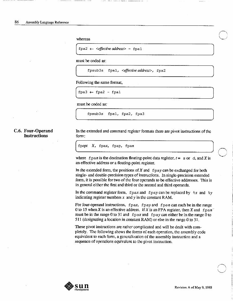
86 Assembly Language Reference
C.6. Four-Operand Instructions
whereas
[ fpa2 ~ <effective address> - fpal
must be coded as:
fpsub3s fpal, <effective address>, fpa2
Following the same format,
[ fpa3 ~ fpa2 - fpal
must be coded as:
[ fpsub3s fpal, fpa2, fpa3
In the extended and command register formats there are pivot instructions of the form:
)
)
)
( fpopt X, fpax, fpay, fpan J '----· --~---------' 0
where fpan is the destination floating-point data register, t = s or d, and X is an effective address or a floating-point register.
In the extended form, the positions of X and fpay can be exchanged for both single- and double-precision types of instructions. In single-precision extended form, it is possible for two of the four operands to be effective addresses. This is in general either the first and third or the second and third operands.
In the command register form, fpax and fpay can be replaced by %x and %y indicating register numbers x and y in the constant RAM.
For four-operand instructions, fpax, £pay and fpan can each be in the range 0 to 15 when X is an effective address. If X is an FP A register, then X and fpan ~ must be in the range 0 to 31 and fpax and fpay can either be in the range 0 to 511 (designating a location in constant RAM) or else in the range 0 to 31.
These pivot instructions are rather complicated and will be dealt with completely. The following shows the forms of each operation, the assembly code equivalent to each form, a generalization of the assembly instruction and a sequence of operations equivalent to the pivot instruction.
sun microsystems
Revision A of May 9, 1988

c fpma{s,d} fpma{s,d} fpma{s,d} fpmas
fpms{s,d} fpms{s,d} fpms{s,d} fpmss
Appendix C - FP A Assembler Syntax 87
Instruction
<effective address>, reg2, reg3, reg2, reg3, <effective address>, reg4, reg2, reg3, regl <eal>, reg2, <ea2>, regl
regl regl
Meaning
regl f- reg3 + (reg2 * operand) regl f- operand + (reg3 * reg2)
regl f- reg3 + (reg2 * reg4) regl f- operand2 + (reg2 * operandi)
The fpma instruction, where m stands for multiply, and a stands for add, can be generalized as
[ fpmat X, fpa.x, fpay, fpan l where t is s or d, and X is an <effective address> or one of the floating~ point data registers. In the extended type of instruction, the positions of X and fpay can be exchanged. Also, for single precision either the first and third operands or the second and third operands can be effective addresses. Note that, for example,
[ fpmas dO, fpal, fpa2, fpa3
is equivalent to the following sequence of instructions
fpmul3s fpadd3s fpmoves
dO, fpal, temp temp, fpa2, temp temp, fpa3
where temp is a temporary register.
Instruction Meaning
<effective address>, reg2, reg3, regl regl f- reg3 - (reg2 * operand) reg2, reg3, <effective address>, regl regl f- operand- (reg3 * reg2) reg4, reg2, reg3, regl regl f- reg3- (reg2 * reg4) <eal>, reg2, <ea2>, regl regl f- operand2- (reg2 *operandi)
The fpms instruction, where m stands for multiply, and s stands for subtract, can be generalized as
[ fpmst X, fpax,fpay,fpan
where tis s or d, and X is an <effective address> or one of the floating-point data registers. In the extended type of instruction, the positions of X and fpay can be exchanged. Also, in siQgle-precision two-memory instructions~; either the first and third operands or the second and third operands can be effective addresses. Note that, for example,
l
)
[ fpmss fpal, fpa2, dO, fpa3 J
'--· ------
Revision A of May 9, 1988

88 Assembly Language Reference
fpmr{s,d} fpmr{s,d} fpmr{s,d} fpmrs
is equivalent to the following sequence of instructions
fpmul3s fpsub3s fpmoves
fpal, fpa2, temp temp, dO, temp temp, fpa3
The fpmr instruction, where m stands for multiply, and r stands for reverse subtract, can be generalized as
[ fpmrt X, fpax,fpay,fpan
where tis s or d, and X is an <effective addresS> or one of the floating-point data registers. In the extended type of instruction, the positions of X and fpay can be exchanged.
Instruction Meaning
<effective address>, reg2, reg3, regl regl <-- ( -reg3) + (reg2 * operand) reg2, reg3, <effective address>, regl regl <--(-operand) + (reg3 * reg2) reg4, reg2, reg3, regl regl <-- (-reg3) + (reg2 * reg4) <eal>, reg2, <ea2>, regl regl <-- (-operand2) + (reg2 *operandi)
J
(\, \ I '-._j
In single-precision extended form either the first and third operands or the second (j and third operands can be effective addresses. Note that, for example, "-~
[fpmrs dO, fpal, fpa2, fpa3
is equivalent to the following sequence of instructions:
fpmul3s fpsub3s fpmoves
dO, fpal, temp fpa2, temp, temp temp, fpa3
The fpam instruction, where a stands for add, and m stands for multiply, can be generalized as
[ fpamt X, fpax,fpay,fpan
where tis s or d, and X is an <effective addresS> or one of the floating-point data registers. In the extended type of instruction, the positions of X and fpay can be exchanged.
J
J
Revision A of May 9, 1988
.r-\ '0
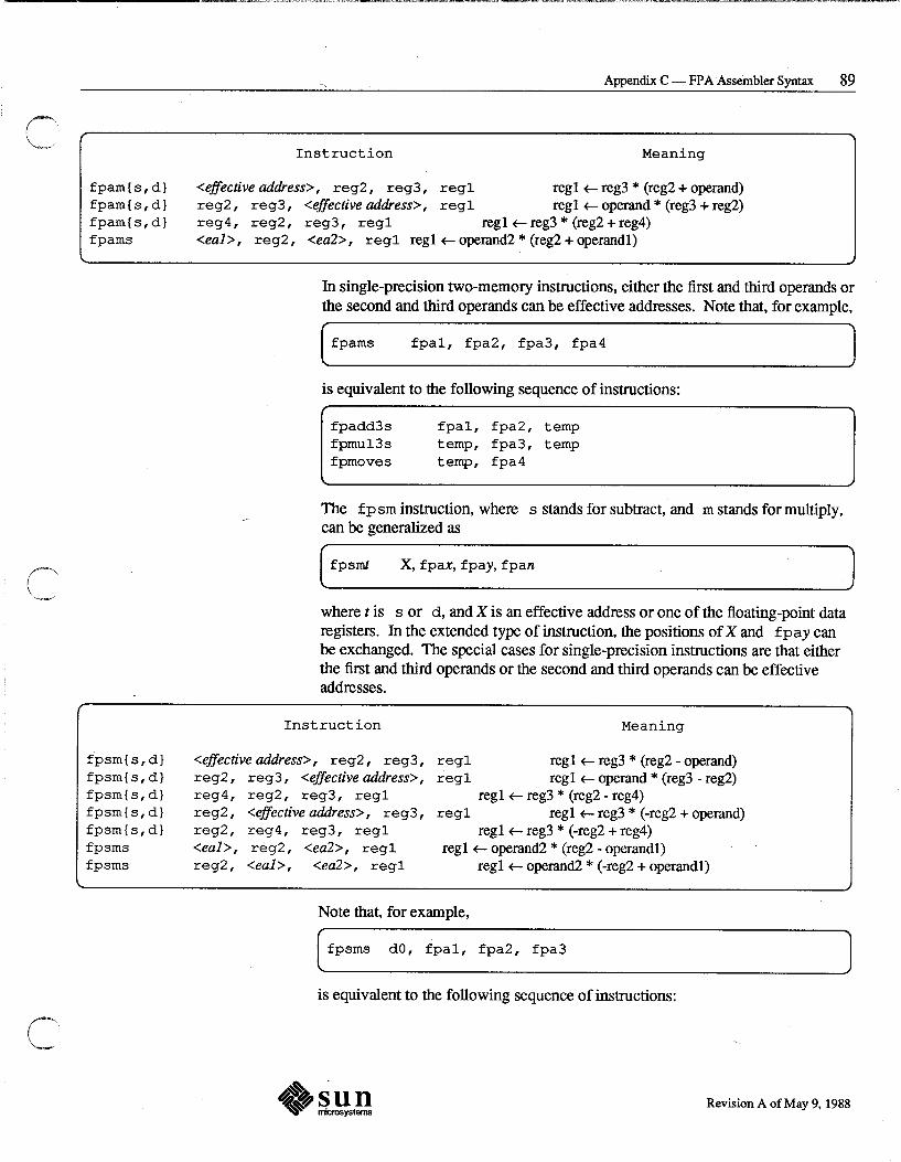
c
fpam{s,d} fpam{s,d} fpam{s,d} fpams
fpsm{s,d} fpsm{ s, d} fpsm{s,d} fpsm{ s, d} fpsm{ s, d} fpsms fpsms
Appendix C- FP A Assembler Syntax 89
Instruction Meaning
<effective address>, reg2, reg3, regl reg I ~ reg3 * (reg2 + operand) reg2, reg3, <effective address>, regl reg I ~ operand * (reg3 + reg2) reg4, reg2, reg3, regl reg I ~ reg3 * (reg2 + reg4) <eal>, reg2, <ea2>, regl reg I ~ operand2 * (reg2 +operandi)
In single-precision two-memory instructions, either the first and third operands or the second and third operands can be effective addresses. Note that, for example,
( fpams fpal, fpa2, fpa3, fpa4
is equivalent to the following sequence of instructions:
fpadd3s fpmul3s fpmoves
fpal, fpa2, temp temp, fpa3, temp temp, fpa4
The fp sm instruction, where s stands for subtract, and m stands for multiply, can be generalized as
( fpsrnt X,fpax,fpay,fpan
where t is s or d, and X is an effective address or one of the floating-point data registers. In the extended type of instruction, the positions of X and fpay can be exchanged. The special cases for single-precision instructions are that either the first and third operands or the second and third operands can be effective addresses.
Instruction
<effective address>, reg2, reg3, reg2, reg3, <effective address>, reg4, reg2, reg3, regl reg2, <effective address>, reg3, reg2, reg4, reg3, regl <eal>, reg2, <ea2>, regl reg2, <eal>, <ea2>, regl
Meaning
regl reg I~ reg3 * (reg2- operand) regl reg I ~ operand * (reg3 - reg2)
reg I~ reg3 * (reg2- reg4) regl regi ~ reg3 * (-reg2 +operand)
reg I~ reg3 * (-reg2 + reg4) regi ~ operand2 * (reg2- operandi)
regi ~ operand2 * (-reg2 +operandi)
Note that, for example,
( fpsms dO, fpal, fpa2, fpa3
is equivalent to the following sequence of instructions:
l
l
l
Revision A of May 9, 1988

90 Assembly Language Reference
C. 7. Other Instructions
Table C-1
Mnemonic
fpnop
fptstt
fpcmpt
fpmcmpt
fpmovet
fpmove2t
fpmove3t
fpmove4t
fpdot2t
fpdot3t -
fpdot4t
fptran2t
fptran3t
fptran4t
fpmove
fpmove
fpmove
fpsub3s fpmul3s fpmoves
dO, fpal, temp temp, fpa2, temp temp, fpa3
Other special instructions are listed below. In each of them the last operand is also the destination, except for tst, cmp and mcmp where fpastatus is the implied destination. X is either an effective address or an FP A data register and tis either s or d for'all instructions except fpmovet, where t can be s, d,or 1.
Other Instructions
Operand Operation Name
nop
X operand compare with zero
X, fpam register m compare with operand
X, fpam register m compare magnitude with operand
fpam, fpan move floating-point registers
fpam, fpan 2x2 matrix move
fpam, fpan 3x3 matrix move
fpam, fpan 4x4 matrix move
fpax, fpay, fpan fpan ~ fpax*fpay +
(fpa.x+l) * (fpay+l)
fpax, fpay, fpan fpan ~ fpax*fpay +
(fpa.x+l) * (fpay+l) +
(fpax+2) * (fpay+2)
fpax, fpay, fpan fpan ~ fpax*fpay +
(fpax+l)*(fpay+l) + (fpax+2)*(fpay+2) +
(fpax+3)*(fpay+3)
fpam, fpan transpose 2x2 matrix
fpam, fpan transpose 3x3 matrix
fpam, fpan transpose 4x4 matrix
fpamode, <ea> read mode register
<ea>, fpamode write to mode register
fpastatus, <ea> read status register
fpmove <ea>, fpastatus write to status register
fpmovet fpam, <ea> read a floating-point data register
fpmO'I.-et <ea>, fpan write to a floating-point data register
Revision A of May 9, 1988

c
C.S. Restrictions and Errors
C.9. Instruction Set Summary
Table C-2
Instruction Operand fpnegs X, fpan
fpnegd X, fpan
fpabss X, fpan fpabsd X, fpan
fpltos X, fpan fpltod X, fpan
fpstol X, fpan fpdtol X, fpan
fpstod X, fpan fpdtos X, fpan
£psqrs X, fpan fpsqrd X, fpan
fpadds X, fpan fpadd3s X, fpam, fpan
fpaddd X, fpan fpadd3d X, fpam, fpan
fpsubs X, fpan fpsub3s X, fpam, fpan fprsubs <ea>, fpan
fpsubd X, fpan fpsub3d X, fpam, fpan fprsubd <ea>, fpan
fpmuls X, fpan fpmul3s X, fpam, fpan
Appendix C- FP A Assembler Syntax 91
In double-precision instructions, when absolute short addressing or a single data or address register is used, as reports an invalid operand error.
For the dot product and matrix move and transpose instructions, when the register specified does not fall within the specified range, as reports a register out of range error.
For most instructions where one operand is an effective address, the register range is 0 to 15. If all operands are FPA registers, then the register range is 0 to 31. For constant RAM registers, the range is 0 to 511. as reports an invalid operand error when any of these registers are not within the permitted range.
In the following table, X is any valid MC68020 effective address (the form (m) : w is not allowed for double) or FP A register. In some three- or fouraddress instructions the position of the X and one of the FP A register can be exchanged. This is shown in the fourth column of the following table.
Floating-Point Instructions
Operation Alternative negate single
negate double
absolute value single
absolute value double
convert integer to single convert integer to double
convert single to integer convert double to integer
convert single to double
convert double to single
square single
square double
add single
add single fpam, X, fpan
add double
add double fpam, X, fpan
subtract single
subtract single fpam, X, fpan reverse subtract single
subtract double subtract double fpam, X, fpan reverse subtract double
multiply single
multiply single fpam, X, fpan
sun microsystems
Revision A of May 9, 1988

92 Assembly Language Reference
Table C-2 Floating-Point Instructions-- Continued
Instruction Operand Operation Alternative
fpmuld X, fpan multiply double
fpmul3d X, fpam, fpan multiply double fpam, X, fpan
fpdivs X, fpan divide single
fpdiv3s X, fpam, fpan divide single fpam, X, fpan
fprdivs <ea>, fpan reverse divide single
fpdivd X, fpan divide double
fpdiv3d X, fpam, fpan divide double fpam, X, fpan
fprdivd <ea>, fpan reverse divide double
fpnop nop
fptsts X single compare with 0
fptstd X double compare with 0
fpcmps X, fpam single compare
fpcmpd X, fpam double compare
fpmcmps X, fpam single magnitude compare
fpmcmpd X, fpam double magnitude compare
fpsins fpax, fpan sine single
fpsind fpax, fpan sine double
fpcoss fpax, fpan cosine single
fpcosd fpax, fpan cosine double 0
fpatans fpax, fpan atan single
fpatand fpax, fpan atandouble
fpetoxs fpax, fpan e~x single
fpetoxd fpax, fpan e~x double
fpetoxmls fpax, fpan e~x-1 single
fpetoxmld fpax, fpan e~x-1 double
fplogns fpax, fpan ln(x) single
fplognd fpax, fpan ln(x) double
fplognpls fpax, fpan ln(1+x) single
fplognpld fpax, fpan ln(l+x) double
fpsincoss fpax, fpac:fpas fpac +- cosine(x), fpas +- sine (x)
fpsincosd fpax, fpac:fpas fpac +- cosine(x), fpas +- sine (x)
fpmas X, fpax, fpay, fpan fpan +- (fpax *X)+ fpay fpax, X, fpay, fpan
fpay, fpax, X, fpan
X, fpax, X, fpan
fpax, X, X, fpan
fpmad X, fpax, fpay, fpan fpan +- (fpax *X) + fpay fpax, X, fpay, fpan
fpay, fpax, X, fpan
fpmss X, fpax, fpay, fpan fpan +- fpay - (fpax * X) fpax, X, fpay, fpan
fpay, fpax, X, fpan
X, fpax, X, fpan
fpax, X, X, fpan
Revision A of May 9, 1988

Appendix C- FP A Assembler Syntax 93
c Table C-2 Floating-Point Instructions- Continued
Instruction Operand Operation Alternative fpmsd X, fpax, fpay, fpan fpan~ fpay - (fpax * x) fpax, X, fpay, fpan
fpay, fpax, X, fpan
fpmrs X, fpax, fpay, fpan fpan ~ (fpax * x)- fpay fpax, X, fpay, fpan
fpay, fpax, X, fpan
\ X, fpax, X, fpan
fpax, X, X, fpan
fpmrd X, fpax, fpay, fpan fpan ~ (fpax * x)- fpay fpax, X, fpay, fpan
fpay, fpax, X, fpan
fpams X, fpax, fpay, fpan fpan ~ (fpax + x) * fpay
- fpax, X, fpay, fpan
fpay, fpax, X, fpan
X, fpax, X, fpan
fpax, X, X, fpan
fpamd X, fpax, fpay, fpan fpan ~ (fpax + x) * fpay
fpax, X, fpay, fpan
fpay, fpax, X, fpan
fpsms X, fpax, fpay, fpan fpan ~ (fpax- x) * .fpay
fpax, X, fpay, fpan
fpay, fpax, X, fpan
X, fpax, X, fpan
fpax, X, X, fpan
fpsmd X, fpax, fpay, fpan fpan ~ (fpax- x) * fpay
fpax, X, fpay, fpan
fpay, fpax, X, fpan
fpmoves <ea>, fpan write to a register, single
fpmoved <ea>, fpan write to a register, double
fpmovel ·<ea>, fpan write to a register, integer
fpmoves fpam, <ea> read a register, single
fpmoved fpam, <ea> read a register, double
fpmove2s fpam, fpan 2x2 matrix move, single
fpmove2d fpam, fpan 2x2 matrix move, double
fpmove3s fpam, fpan 3x3 matrix move, single
fpmove3d fpam, fpan 3x3 matrix move, double
fpmove4s fpam, fpan 4x4 matrix move, single
fpmove4d fpam, fpan 4x4 matrix move, double
fpdot2s fpax, fpay, fpan fpan ~ fpax* fpay + (fpax+l) * (fpay+l)
fpdot2d fpax, fpay, fpan fpan ~ fpax* fpay + (fpax+l) * (fpay+l)
fpdot3s fpax, fpay, fpan fpan ~ fpax* fpay + (fpax+l) * (fpay+l) +
(fpax+2) * (fpay+2)
fpdot3d fpax, fpay, fpan fpan~ fpax*fpay + (fpax+l) * (fpay+l) +
(fpax+2) * (fpay+2)
c Revision A of May 9, 1988

94 Assembly Language Reference
Table C-2 Floating-Point Instructions-- Continued
Instruction Operand Operation Alternative fpdot4s fpax, fpay, fpan fpan ~ fpax* fpay + (fpax+l)*(fpay+l) +
(fpax+2)*(fpay+2) + (fpax+3)*(fpay+3)
fpdot4d fpax, fpay, £pan fpan ~ fpax* fpay + (fpax+l) * (fpay+l) +
(fpax+2)*(fpay+2) + (fpax+3)*(fpay+3)
fptran2s fpam, fpan transpose 2x2 matrix, single
fptran2d fpam, fpan transpose 2x2 matrix, double
fptran3s fpam, fpan transpose 3x3 matrix, single
fptran3d fpam,fpan transpose 3x3 matrix, double
fptran4s fpam, fpan transpose 4x4 matrix, single
fptran4d £pam, £pan transpose 4x4 matrix, double
fpmove fpamode, <ea> read the mode register fpmove <ea>, fpamode write on mode register
fpmove fpastatus, <ea> read the status register
fpmove <ea>, fpastatus write to status register
~~sun ~~ microsystems Revision A of May 9, 1988
c
c
Index
A absolute expressions, 18 thru 19 addressing categories, 46 thru 47
alterable, 46 control, 46 data, 46 memory,46
addressing modes, 42 thru 45 . align directive, 37 . ascii directive, 32 . asciz directive, 33 assembler directives, 31 thru 38
.align, 37
.ascii, 32
.asciz, 33 ,bss, 34 .byte, 33 . co nun, 36 .data, 34 .even, 37 .globl, 36 .lconun, 35 .long, 33 .proc, 38 . skip, 35 .text, 34 .word, 33
assembler options, 3 thru 4 -d2,4 -h,4 -j,4 -k,3 -L,3 -m68010, 3 -m68020, 3 -o,3 -R,3
assignment statements, 26 thru 27
B basic elements, 9 thru 13 . bss directive, 34 .byte directive, 33
\
-95-
c character set, 9 . comm directive, 36 comment field, 26 constants, 11 thru 12
decimal, 11 floating-point, 12 hexadecimal, 11 numeric, 11 octal, 11 string, 12
D -d2 option, 4 . data directive, 34 decimal constants, 11 direct assignment, 26 thru 27 directives, 31 thru 38
.align, 37
.ascii, 32
.asciz, 33
.bss, 34
.byte, 33
. conun, 36
.data, 34
.even, 37
.globl, 36
.lconun, 35
.long, 33
.proc, 38
. skip, 35
.text, 34
.word, 33
E Error Codes, 51 . even directive, 37 expressions, 17 thru 19
absolute, 18 thru 19 external, 18 thru 19 operators, 17 relocatable, 18 thru 19 terms, 18
external expressions, 18 thru 19

Index- Continued
F floating-point constants, 12 FP A Assembler Syntax, 83 thru 90
G . globl directive, 36
H -hoption, 4 hexadecimal constants, 11
I identifiers, 9 thru 10 Instruction Syntax, 83 Instructions, Two-Operand, 84
J -j option, 4
K -k option, 3
L -L option, 3 label field, 23 thru 24 labels, 10 thru 11
local, 10 numeric, 10 scope, 10
.lcomm directive, 35 lexical elements, 9 thru 13 lines, 23 local labels, 10 location counter, 12 .long directive, 33
M -m68010 option, 3 -m.68020 option, 3
N notation, 4 thru 5 numeric constants, 11 numeric labels, 10
0 -o option, 3 octal constants, 11 operand field, 25 thru 26 Operand Types, 84 operation code field, 24 thru 25 options, 3 thru 4
-k,3 -d2,4 -h,4 -j,4 -L,3 -m68010, 3 -m68020, 3
-96-
options, continued -o,3 -R,3
p . proc directive, 38 program layout, 23 thru 27 pseudo-ops, 31 thru 38
.align, 37
.ascii, 32
.asciz,33
.bss, 34
.byte, 33
. comm, 36
.data, 34
.even, 37
.globl, 36
.lcomm, 35
.long, 33
.proc, 38
. skip, 35
.text, 34
.word, 33
R -R option, 3 register operands, 25 thru 26
address registers, 42 data registers, 42 special registers, 42
Register Syntax, 84 relocatable expressions, 18 thru 19
s scope of labels, 10 . skip directive, 35 special register operands
cc,42 dfc,42 fpcr,42 fpiar,42 fpsr, 42 pc,42 sfc,42 sp,42 sr,42 usp,42
statements, 23 comment field, 26 direct assignment, 26 thru 27 label field, 23 thru 24 operand field, 25 thru 26 operation code field, 24 thru 25
string constants, 12
T . text directive, 34 Two-Operand Instructions, 84
0
0

Index- Continued
c u Usage Errors, 51
w . word directive, 33
c -97-