Embed Size (px)
Citation preview

Everything Needed to Build-
-Material List
-Cut List
-Fully Illustrated Plans
-Operation Instructions
The EASYThe EASYThe EASYThe EASY
BALANCEBALANCEBALANCEBALANCE
AUTO
ROTISSERIE
Fabrication andAssembly Plans
Hydraulic Jacking
Rock Solid Disc Brake Locks
Hand Crank Balance System
Portable
Adjustable For Any Vehicle

Innovative Hand Crank Balance System
Rock Solid Disc Brake Mechanism
Adjustable Vehicle Mounts
Retractable Legs For Easy Transportation
Reinforcements For High Stress Areas
Easy Hydraulic Jacking System
Choice Of Size Of Casters
Multiple Height Positions Using Lock Pins
-Balances car perfectly in just a few minutes with vehicle mounted on rotisserie-Eliminates pendulum effect-Vehicle can be turned with one hand-Allows on-the-fly balance adjustments as components are removed or installed on vehicle
-Adjustable to almost five feet for any vehicle width
-Legs retract into base to allow rotisserie to fit in four foot wide spaces, such as truck beds-Legs extend to a wide six feet for extra stability
-Legs can be built to accommodate different caster wheel sizes from 3" to 10", pneumatic or solid
-Allows vehicle to be raised from a 19" bumper height to desired working position, up to almost four feet off the ground
-Strong, positive locking mechanism-Holds vehicle in any position
-Locking pins provide extra safety measure against accidental jack malfunction
Strategically Located Jam Bolts
-Jam bolts stabilize rotisserie to reduce vehicle rocking and swaying
Adjustable Body Length Connectors
-Tubing connectors allow bodies up to 18 feet long to be mounted to rotisserie-Single tubing assembly is out of the way, easy to work around-Can also be used to connect both ends of rotisserie assemblies for easy movement around the shop and compact storage (approximately a 4' x4' area)
Optional Screw Jacks
-Quick And Easy AdjustmentFor Extra Stability When UsingPneumatic Casters
Easy Balance Rotisserie
Copyright © 2006 Larry DuBois11/4/06

Exploded View
Head Assembly Rotator Assembly
Cross Mount Assembly
UprightR
F
EN
X
G
AKA
S
S
AB
Q
AN
Base Assembly
D
E
C
N
O
AH
O
B
AB
Z
P
AA
Y
Y
Y
T
AJ
T
AJ
AM
AC
B
AH
AE
AL
AO
AS (6" Casters)
AT (10" Casters)
Leg Assembly
Cross Mount Arm
Copyright © 2006 Larry DuBois11/4/06

9" AdjustmentRange Of Balancer
65"
5"
25" - 44"Pivot Point
Lifting Range
47" Maximum HeightOf Bumper Mount
19" Minimum HeightOf Bumper Mount
Key Dimensions
Copyright © 2006 Larry DuBois8/4/07

Rotisserie Storage
Copyright © 2006 Larry DuBois8/4/07

Material List
(All square tubing is 3/16" wall except 1" square tubing, which is 1/8").Metal
Size Description Length3" Square Tubing 6"2 1/2" Square Tubing 43' 2" Square Tubing 52'1" Square Tubing 8'2 1/2" Schedule 40 Pipe 2'2" Schedule 40 Pipe 2'2" x 2" x 3/16" Angle 9"8" x 1/4" Strap 17"4" x 3/8" Strap 9"4" x 1/4" Strap 33"4" x 3/16" Strap 36"3 1/2" x 1/4" Strap 38"3" x 3/16" Strap 7"2" x 1/2" Strap 9"2" x 3/16" Strap 22"1 1/2" x 3/16" Strap 7"1" x 1/4" Strap 17"1/4" Square Stock 9"
Hardware
Size Description Quantity3/8" x 3" Carriage Bolt 23/8" x 3 1/2" Bolt 203/8" x 1" Bolt 541/4" x 3/4" Bolt 81/2" Nut 81/2" Lock Nut 63/8" Nut 801/2" Lock Washer 103/8" Lock Washer 381/4" Lock Washer 87/16" Flat Washer 25/16" Flat Washer 543/8" x 1/2" x 2" Steel Spacer 21/2" Threaded connector 23/8" Threaded Connector 41/2" x 4" Clevis Pin 101/2" All Thread 6' (When Using 6" Casters)1/2" All Thread 7' (When Using 10" Casters)
Shifter Ball 2 (HELP! #76933 or Equiv.)Torrington Bearing 2 (McMaster-Carr #5909K31 or Equiv.)Bearing Washers 4 (McMaster-Carr #5909K44 or Equiv.)3 Ton Hydraulic Jack 2 (Northern #144878 or Equiv.)
(25" - 44 1/2" Operating Range)6" Pneumatic Caster 4 (Northern #189222 or Equiv.)10" Pneumatic Caster 4 (Northern #11000 or Equiv
2/10/07 Copyright © 2006 Larry DuBois

Cut List
Label Material Name # Of Pieces Length A 3" Square Tubing Rotator Top Cover Side 2 1" B 2 1/2" Square Tubing Lateral Base 2 41" * C 2 1/2" Square Tubing Longitudinal Base 2 18" * D 2 1/2" Square Tubing Base Upright 2 18" * E 2 1/2" Square Tubing Jack Mount, (Upper and Lower) 4 5" * F 2 1/2" Square Tubing Head Slider 2 19" * G 2 1/2" Square Tubing Rotator Housing 2 22" * H 2 1/2" Square Tubing Base Connector 1 54" * I 2 1/2" Square Tubing Base Connector 1 48" * J 2 1/2" Square Tubing Base Connector 1 42" * K 2 1/2" Square Tubing Base Connector 1 36" * L 2 1/2" Square Tubing Base Connector 1 30" * M 2 1/2" Square Tubing Base Connector 1 24" * N 2 1/2" Square Tubing Jack Mount 4 2 1/2" * O 2" Square Tubing Leg 4 16" * P 2" Square Tubing Leg Insert 4 22 1/2" * Q 2" Square Tubing Cross Mount Upright 2 22" * R 2" Square Tubing Main Upright 2 57" * S 2" Square Tubing Lateral Cross Mount 2 60" * T 2" Square Tubing Cross Mount Attach Arm 4 12" * U 2" Square Tubing Base Connector Link 6 15" * V 2" Square Tubing Connector Link (For Rottiserie Storage) 1 24" * W 2" Square Tubing Leg Extension (10" Casters) 4 4" * X 1" Square Tubing Head Brace 2 11 1/2" Y 1" Square Tubing Base Upright Brace 6 11 1/2" Z 2 1/2" Schedule 40 Pipe Rotator Outer Pipe 2 9" AA 2" Schedule 40 Pipe Rotator Inner Pipe 2 9 1/2" AB 2" x 2" x 3/16" Angle Cross Mount Brace 4 2" AC 8" x 1/4" Strap Brake Rotor 2 8" AD 4" x 3/8" Strap Brake Assembly Spacer Plate 2 4" AE 4" x 1/4" Strap Stabilizer Jack Base Plate 4 4" AF 4" x 1/4" Strap Inner Brake Pad 2 3 3/4" AG 4" x 1/4" Strap Outer Brake Pad 2 3 3/4" AH 4" x 3/16" Strap Caster Mount 4 4 1/2" AI 4" x 3/16" Strap Brake Assembly Backing Plate 2 8" AJ 3 1/2" x 1/4" Strap Attach Arm Mount 8 4 1/2" AK 3" x 3/16" Strap Rotator Top Cover 2 3" AL 2" x 1/2" Strap Stabilizer Jack Swivel Block 4 2" AM 2" x 3/16" Strap Cross Mount Top Plate 2 2" AN 2" x 3/16" Strap Cross Mount Brace 4 4" AO 1 1/2" x 3/16" Strap Stabilizer Jack Top Plate 4 1 1/2" AP 1" x 1/4" Strap Balance Jack Crank Handle 2 8" AQ 1/4" Square Stock Brake Pad Spacer 2 4" AR 1/2" Threaded Rod Balance Jack Assembly 2 14" AS 1/2" Threaded Rod Stabilizer Jack (6" Casters) 4 11" AT 1/2" Threaded Rod Stabilizer Jack (10" Casters) 4 13" * To minimize waste, cut tubing as follows:
Cut details for 2 1/2" tubing:Pieces B, C, D, and E, F and M are cut from 20' length of 2 1/2" tubing.Pieces G, H, I, J, K and N are cut from 20' length of 2 1/2" tubing.Piece L is cut from 3' length of 2 1/2" tubing.
Cut details for 2" tubing:Pieces O, P, Q, V and W (W is for 10" Casters) are cut from 20' length of 2" tubing.Pieces R and S are cut from 20' length of 2" tubing.Pieces T, and U, are cut from 12' length of 2" tubing.
2/10/07 Copyright © 2006 Larry DuBois

R
2"
1"
1"
D
1"
1"
B
1/2"
Drill Through Both
Sides, Both Holes
3/8" Drill Through
One Side,
Both Holes1/2" Drill Through Both
Sides All Seven Holes
P
7"
1/2" Drill Four Holes
3/4"
Cut 1 1/2" x 1 1/2"
One Side
Q
T
1"
5"
3/8" Drill Through
One Side,
Both Holes
1"
1"
3/8" Drill Through
One Side,
Both Holes
1/2" Drill Through
Both Sides
On One End
Rotated 90o
F
Tap 1/4" x 20 All Four
Sides
A
Drill To Fit Threaded
Rod Connector1/2" 1/2"
AJG
1"
11"
3/8" Drill Through
One Side, Both Holes
1/2"Drill Through Both
Sides, Both Holes
1/4" Drill All Four
Sides
1/2"
1"
3/8" Drill Through
One Side
Both Holes
C
1"
7"
Drill Through
Both Sides
(Size To Match
Jack Mount Bolts)
1 5/8"
NCut Off Side
AH
Drill To FitSpecific Casters
1"
6"
H Through M 4"
O
1/2" Drill Through
Both Sides
AM
Drill Diagram
See Leg Assembly InstructionsBefore Drilling Parts B And P 1/2" Center
AK
F
3 1/8"
3/8" Drill Through One
Side Both Holes
Copyright © 2006 Larry DuBois8/8/07
SEAM ORIENTATION
See Stabilizer
Jack Assembly
Instructions
5"
8"
11"
14"
17"
AP
Drill 1/2" Drill 3/8"
Assembly Notes
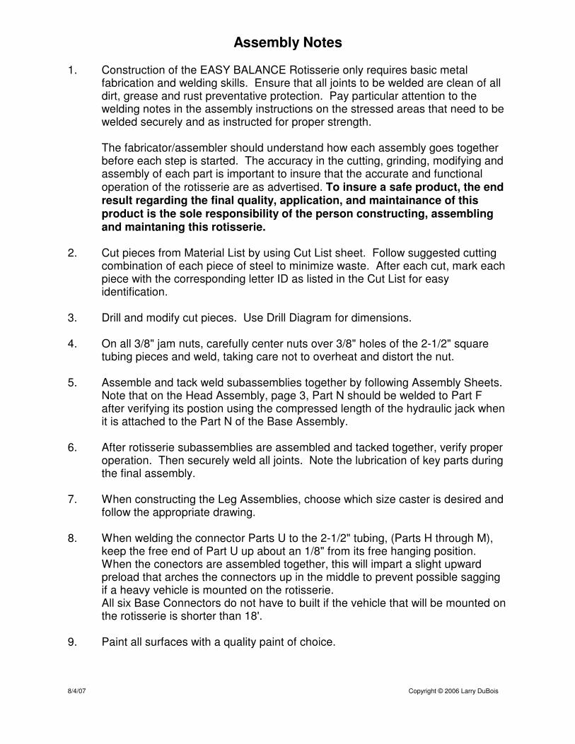
1. Construction of the EASY BALANCE Rotisserie only requires basic metalfabrication and welding skills. Ensure that all joints to be welded are clean of alldirt, grease and rust preventative protection. Pay particular attention to thewelding notes in the assembly instructions on the stressed areas that need to bewelded securely and as instructed for proper strength.
The fabricator/assembler should understand how each assembly goes togetherbefore each step is started. The accuracy in the cutting, grinding, modifying andassembly of each part is important to insure that the accurate and functionaloperation of the rotisserie are as advertised. To insure a safe product, the endresult regarding the final quality, application, and maintainance of thisproduct is the sole responsibility of the person constructing, assemblingand maintaning this rotisserie.
2. Cut pieces from Material List by using Cut List sheet. Follow suggested cuttingcombination of each piece of steel to minimize waste. After each cut, mark eachpiece with the corresponding letter ID as listed in the Cut List for easyidentification.
3. Drill and modify cut pieces. Use Drill Diagram for dimensions.
4. On all 3/8" jam nuts, carefully center nuts over 3/8" holes of the 2-1/2" squaretubing pieces and weld, taking care not to overheat and distort the nut.
5. Assemble and tack weld subassemblies together by following Assembly Sheets. Note that on the Head Assembly, page 3, Part N should be welded to Part Fafter verifying its postion using the compressed length of the hydraulic jack whenit is attached to the Part N of the Base Assembly.
6. After rotisserie subassemblies are assembled and tacked together, verify properoperation. Then securely weld all joints. Note the lubrication of key parts duringthe final assembly.
7. When constructing the Leg Assemblies, choose which size caster is desired andfollow the appropriate drawing.
8. When welding the connector Parts U to the 2-1/2" tubing, (Parts H through M),keep the free end of Part U up about an 1/8" from its free hanging position. When the conectors are assembled together, this will impart a slight upwardpreload that arches the connectors up in the middle to prevent possible saggingif a heavy vehicle is mounted on the rotisserie.All six Base Connectors do not have to built if the vehicle that will be mounted onthe rotisserie is shorter than 18'.
9. Paint all surfaces with a quality paint of choice.
8/4/07 Copyright © 2006 Larry DuBois

Base Assembly
D
E
C
N
B
Y
Y
Y
1
Copyright © 2006 Larry DuBois8/4/07

Base Assembly 2
E
N
Copyright © 2006 Larry DuBois11/4/06

Base Assembly
D
E
N
D
E
N
3/8" x 1" Bolt
And 3/8' Nut
3 1/2"
Rotated View
3/8" x 1" Bolt
And 3/8' Nut
3
Copyright © 2006 Larry DuBois11/4/06

Base Assembly
C
B
D
N
Center Parts C And D On Part BCut Support (X) Ends At45 Degrees And Mount As Required
Y
YY
Tilt Top Of Upright (D) 1/4" BackWhen Welding to Base (B)
3/8" x 1" Bolt
And 3/8' Nut
3/8" x 1" Bolt
And 3/8' Nut
4
Copyright © 2006 Larry DuBois8/4/07

Head Assembly
N
X
E
F
Z
AC
1
Copyright © 2006 Larry DuBois11/4/06

Head Assembly
E
Center Part N on Part E
N
2
Copyright © 2006 Larry DuBois11/4/06

Head Assembly
E
F
N
3/8" x 1" BoltAnd 3/8" Nut
Locate Seam Of Tubing
To One Side
3
Copyright © 2006 Larry DuBois01/12/07
3/8" x 1" BoltAnd 3/8" Nut
N
E
F
3/8" x 1" BoltAnd 3/8' Nut
ROTATED VIEW
NOTE: THIS DIMENSION TO BE DETERMINED BY LENGTH OF COMPRESSED HYDRAULIC JACK (SEE ASSEMBLY NOTES)
SEE NOTE

N
X
E
F
Z5 1/2"
Mount Rotor FlushOn End Of Pipe
AC
Cut Support (X) Ends At45 Degrees And Mount As Required
Head Assembly 4
Copyright © 2006 Larry DuBois11/4/06
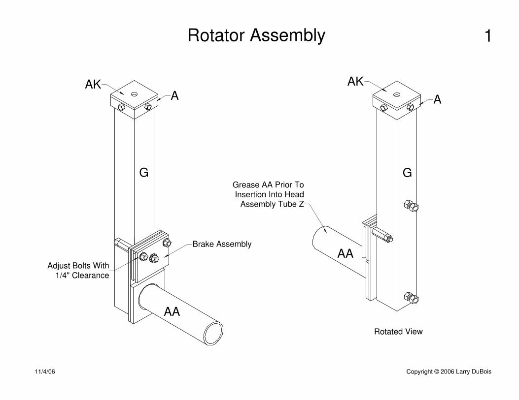
Rotator Assembly
A
G
AA
AK
Brake Assembly
Adjust Bolts With
1/4" Clearance
AA
G
Rotated View
A
AK
1
Grease AA Prior ToInsertion Into Head
Assembly Tube Z
Copyright © 2006 Larry DuBois11/4/06

A
G
AK
3/8" x 1" BoltAnd 3/8" Nut
Brake Assembly(See Brake AssemblyInstallation Sheets)
AA
AA
G
1"
1/4" x 3/4" Bolt
3/8" Rod Connector
And Jam Nut
3/8" x 1" BoltAnd 3/8" Nut
Rotator Assembly 2
Grease AA Prior To
Insertion Into HeadAssembly Tube Z
Copyright © 2006 Larry DuBois11/4/06

Taper Opposite Side As Required
To Clear Welding Bead
G
AA
AI
Brake Assembly Installation
Slide Backing Plate (AI) over Inner Rotator Pipe (AA)and weld to Rotator Housing (G) and Rotator Pipe. Weldaround entire perimeter of Backing Plate and circumferenceof hole around Rotator Pipe.NOTE: ALL WELDS AT THIS JOINT MUST BE SECURE
1
Copyright © 2006 Larry DuBois11/4/06
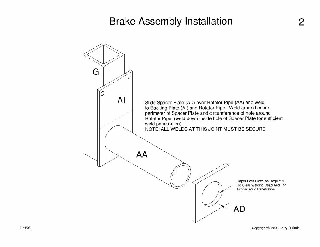
AD
G
AA
Slide Spacer Plate (AD) over Rotator Pipe (AA) and weldto Backing Plate (AI) and Rotator Pipe. Weld around entireperimeter of Spacer Plate and circumference of hole aroundRotator Pipe, (weld down inside hole of Spacer Plate for sufficientweld penetration).NOTE: ALL WELDS AT THIS JOINT MUST BE SECURE
AI
Taper Both Sides As Required
To Clear Welding Bead And For
Proper Weld Penetration
Brake Assembly Installation 2
Copyright © 2006 Larry DuBois11/4/06

AQ
NOTE:Do Not WeldPart AQ to AG
AG
AF
AA
Note Orientation Of RodConnectors To Be Welded To Part G
AI
1. Weld Brake Pad Spacer (AQ) to Inner Brake Pad (AF).2. Temporarily insert bolts through Brake Pads and Backing Plate. Thread rod connectors onto bolts and position as shown and weld to Rotator Housing (G) and Backing Plate (AI).3. During rotisserie final assembly, after Rotator Assembly is inserted into Head Assembly Pipe, place brake pads on either side of Brake Rotor and insert bolts through Brake Pads and into rod couplers.3. With Brake Pads and Brake Rotor seated together against Spacer Plate, adjust bolts to leave approximately 1/4" gap between bolt heads and Outer Brake Pad. Tighten jam nuts to hold this gap.
3/8" x 3 /12" Bolt
3/8" x 1" Bolt
Thread Bolts To 2 1/4"
AD
G
Brake Assembly Installation 3
Copyright © 2006 Larry DuBois11/4/06

4"
3 1/4"
8"
AI
Drill 3/8"
2"
2 3/8"
4"
4"
3 1/4"
3 1/4"
AF
AG
1 3/4"
Drill3/8"
Drill3/8"
Tap 3/8" x 16
2"
Brake Assembly Dimensions
3 3/4"
3 3/4"
1/2"
1/2"
AD
1/4"
4"
4"
4"
2 7/8"
2"
2"
AQ
Copyright © 2006 Larry DuBois11/4/06
1
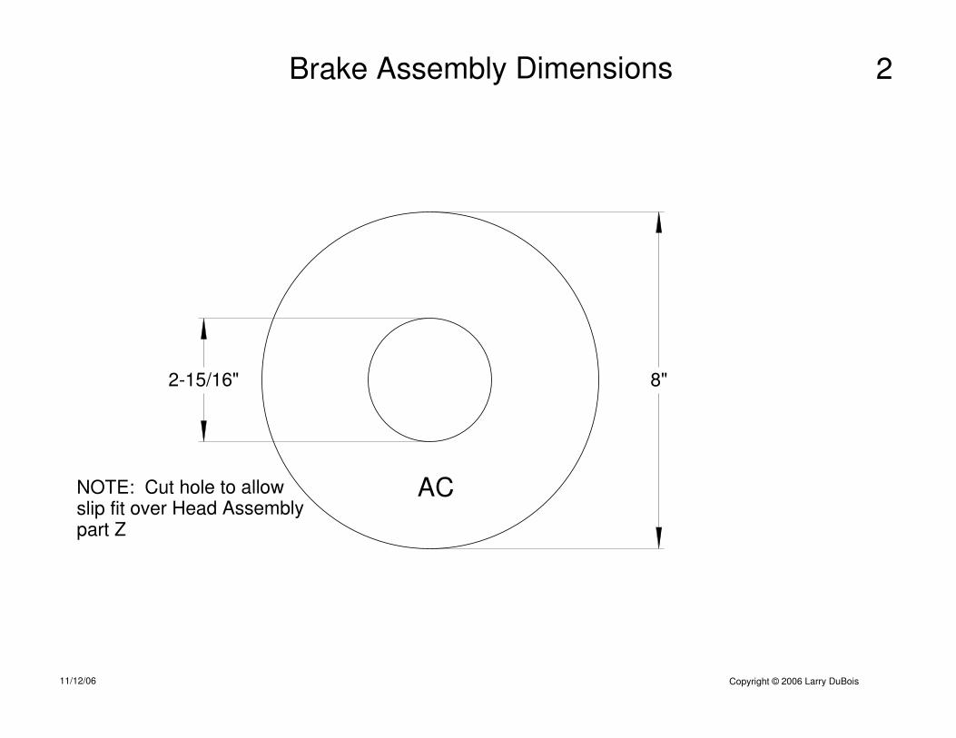
Brake Assembly Dimensions
AC
8"2-15/16"
NOTE: Cut hole to allowslip fit over Head Assemblypart Z
Copyright © 2006 Larry DuBois11/12/06
2

Cross Mount AssemblyAM
Q
T
T
S
AJ
AJ
AB
AN
AB
AN
1
Copyright © 2006 Larry DuBois11/4/06
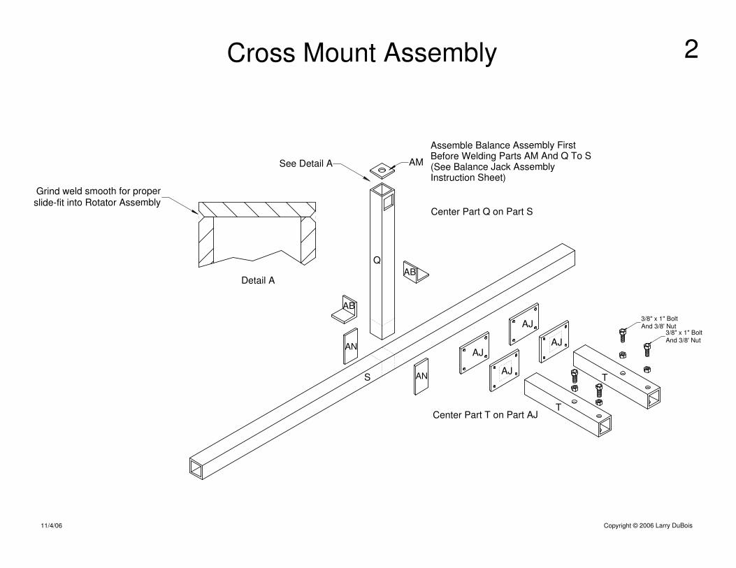
Cross Mount Assembly
AM
Q
T
S
AB
AN
AB
AN T
AJ
Grind weld smooth for proper
slide-fit into Rotator Assembly
Center Part T on Part AJ
Center Part Q on Part S
AJ
AJ
AJ
Assemble Balance Assembly FirstBefore Welding Parts AM And Q To S(See Balance Jack AssemblyInstruction Sheet)
Detail A
3/8" x 1" Bolt
And 3/8' Nut3/8" x 1" Bolt
And 3/8' Nut
2
See Detail A
Copyright © 2006 Larry DuBois11/4/06

Cross Mount
Top Cover
Torrington Bearing
Access Hole
1. Install threaded rod connector, Top Plate (of Cross Mount), then nylon lock nut onto bottom of threaded rod. Install lock nut about 1/4" from bottom of rod. 2. Slide rod connector into Top Plate half way through hole. Weld rod connector to Top Plate. NOTE: Threaded rod must be centered and aligned along center line of Jack Tube G. 3. Weld Top Plate to top of Cross Mount assembly. 4. With rod still in place, insert Cross Mount assembly into Rotator Assembly until rod protrudes from top of Rotator. 5. Install remaining parts on rod in this order from bottom to top: Nut, lock washer, nut, flat washer, Top Cover, bearing washer, torrington bearing, bearing washer, nut, lock washer, Crank Handle, (AP), lock washer, and nut. 6. Tightly jam nuts and lock washers tightly to secure Crank Handle to rod. Top nut should be about 1/8" from end of rod. 7. Thread the next nut below top plate upwards until finger tight, preloading bearing. 8. Tightly jam this nut against remaining nut below. 9. Lightly grease threaded rod and oil Torrington Bearing.10. Install Assembly into Rotator Assembly Tube G and secure Top Cover on G with 1/4" bolts, and lock washers.
(Note) To separate Rotator and Cross Mount, reverse assembly steps. Use access hole in top of Cross Mount to gain access to lock nut.
Balance Jack Assembly Instructions
1. Drill 1/2" hole completly through shifter ball.2. Machine top of ball flat aproximately 7/8" in diameter.3. Grind square section under bolt head until it is the same diameter as bolt.4. Cut spacer so it protrudes from bottom of ball no more than 1/16" when spacer is flush with top of ball.5. Lightly grease bolt, then insert bolt and spacer through top of ball.6. Install flat washer, lock washer and nut.7. Tighten nut against washers and spacer. Ensure that bolt rotates freely.8. Install lock washer, crank handle, lock washer, and nut.9. Jam nuts together tightly.
Top Plate AM
Top Cover AK
Balance Jack Assembly
Cross Mount
Lock Nut
Drill Hole Large Enough
For Rod Connector To Slide Through
Torrington Bearing
w/Bearing Washers
Rotator Assembly
AP
Threaded Rod Connector
3/8" x 3" Carriage Bolt
Spacer
Shifter Ball,Plastic
Bearing Washer
Bearing Washer
A
AK
AR
Top Plate AM
Q
Q
GLightly Grease Threaded Rod
Prior to Insertion Into Tube G
Crank Handle Knob Assembly Instructions
Copyright © 2006 Larry DuBois11/4/06

P
B
Before drilling Leg Inserts, (P), they must be installedin such a way to allow the casters to swivel as they mustbe level to operate properly.1. Insert part P 8" into part B.2. Rotate P inside B (of Base Assembly) in direction shown as far as possible.3. Drill holes through both sides of B and P together 1" from end of B.4. Insert part P farther into B, (keeping P rotated as before) until 2 1/8" is protruding.5. Drill hole in P using previously drilled hole in B as a guide.6. Repeat for other Leg Insert.
P
O
B
P
O
P
O
With B level crosswise and P rotated as shown,
Level O lengthwise and weld as shown
Leg Assemby Details
Copyright © 2006 Larry DuBois11/4/06

Leg Assemblies6" Casters
AH
O
O
P
AH
PCenter Part AHAcross Part O
Drill Holes As Required
To Fit Casters
Holes Are Closest
To Part P Attach Point
Holes Are Closest
To Part P Attach Point
Center Part AHAcross Part O
Copyright © 2006 Larry DuBois11/4/06

Leg Assemblies10" Casters
AH
O
O
P
AH
P
Center Part AHAcross Part O
Drill Holes As Required
To Fit CastersPostion O With Holes Closest
To W Attach Point
W W
Postion O With Holes Closest
To W Attach Point
Center Part AHAcross Part O
Copyright © 2006 Larry DuBois11/4/06

1.5"
1.5"
1/2"
1/2" Threaded Rod
AL
AE
1. Weld Swivel Block (AL) to Base Plate (AE).2. Insert Threaded Rod through Top Plate (AO) and thread Lock Nut onto rod until flush with bottom of rod.3. Partially fill cavity of Swivel Block with wheel bearing grease.4. Place Rod, Top Plate and Lock Nut assembly onto Swivel Block and weld Top Plate to Swivel Block.5. Before drilling 1/2" hole into leg (O), determine hole location after casters have been installed. Insure that adequate clearance exists between jack and caster wheel by turning Threaded Rod through entire range of adjustment.6. Insert Jack Assembly into Leg (O) from bottom and thread Nuts and Washer onto top of Rod as shown.7. Weld bottom Nut to leg assembly.8. Tightly jam top Nuts and Washer together.
Weld Nut To Leg Assembly
Leg Assembly (O)
1/2" Lock Nut
Stabilizer Jack Assembly
1/2" Nut
7/16" Flat Washer
Leg Assembly (O)
4"
4"
2"
2"
7/8"
AO
AL
AE
AO
AE
ALAO
Copyright © 2006 Larry DuBois01/12/07
See Step #5 ForHole Location

H, I, J, K, L, M
U, 6 ea
1. Insert part U into each connector (H through M) at dimension shown. Orient the seam of parts H through M on the right or left side.2. Lay connector assembly on flat surface, support Part U about 1/8" up from free hanging position, weld together in this position as shown in detail drawing.3. Keep orientation as shown when in use.
Detail
U
U
U
U
U
U
H
I
J
K
M
L
Base Connectors
3/8" x 1" BoltAnd 3/8' Nut
3/8" x 1" BoltAnd 3/8' Nut
3"
Copyright © 2006 Larry DuBois8/4/07
NOTE ORIENTATION OF SEAM
1/8" UP FROM FREE
HANGING POSTITION
UP

H I J K L M
18 X X X X X X
17.5 X X X X X X (Cut Piece "H" To 48")
17 X X X X X X (Cut Piece "H" To 42")
16.5 X X X X X X (Cut Piece "H" To 36")
16 X X X X X
15.5 X X X X X
15 X X X X X
14.5 X X X X X
14 X X X X X
13.5 X X X X
13 X X X X
12.5 X X X X
12 X X X X
11.5 X X X X
11 X X X X
10.5 X X X
10 X X X
9.5 X X X
9 X X X
8.5 X X X
8 X X X
7.5 X X X
7 X X
6.5 X X
6 X X
5.5 X X
5 X X
4.5 X X
4 X X
3.5 X X
3 X
2.5 X
2 X
1.5 X
1 X
0.5 X
11/4/2006 Copyright © 2006 Larry DuBois
Connector Usage Chart
Connector Sections
To UseVehicle
Length
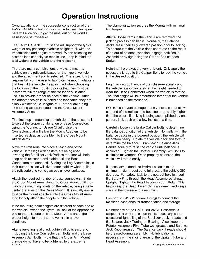
Operation InstructionsCongratulations on the successful construction of theEASY BALANCE Auto Rotisserie! A few minutes spenthere will allow you to get the most out of the world’seasiest-to-use rotisserie!
The EASY BALANCE Rotisserie will support the typicalweight of any passenger vehicle or light truck with thetransmission and engine removed. When selecting thecaster’s load capacity for mobile use, keep in mind thetotal weight of the vehicle and the rotisserie.
There are many combinations of ways to mount avehicle on the rotisserie based on the type of vehicleand the attachment points selected. Therefore, it is theresponsibility of the user to fabricate the mount adaptersthat best fit the vehicle. Keep in mind when choosingthe location of the mounting points that they must belocated within the range of the rotisserie’s BalanceJacks to provide proper balance of the vehicle. Afterthe adapter design is selected and fabricated, they aresimply welded to 12" lengths of 1-1/2" square tubing. This tubing will be inserted into the Cross MountAssembly Arms.
The first step in mounting the vehicle on the rotisserie isto select the proper combination of Base Connectorsusing the “Connector Usage Chart”. Use theConnectors that will allow the Mount Adapters to beinserted as deep as possible into the Cross MountAttach Arms.
Move the rotisserie into place at each end of thevehicle. If the legs with casters are being used,lowering the Stabilizer Jack Pads to the floor will helpkeep each rotisserie end stable until the BaseConnectors are attached. Sliding the Leg Assemblies totheir outer position will give better stability when rollingthe rotisserie and vehicle across unlevel surfaces.
Attach the required number of base connectors. Slidethe Cross Mount Arms along the Cross Mount until theymatch the mounting points on the vehicle, being sure tocenter the arms on the Cross Mount. It is usually easierto slide the mount adapters into the Cross Mount Armsthen loosely attach the adapters to the vehicle.
If the mounting point heights are different at each end ofthe vehicle, extend the Hydraulic Jack at the appropriateend of the rotisserie until the Mount Arms are at theproper height to mount to the vehicle in a levelcondition.
After everything is aligned, tighten all bolts securely,including the Base Connector Jam Bolts and the BaseAssembly Jam Bolts. Note that the Cross Arm Mountclamps do not have to be tightened to the extreme.11/04/06
The clamping action secures the Mounts with minimalbolt torque.
After all loose items in the vehicle are removed, thejacking process can begin. Normally, the BalanceJacks are in their fully lowered position prior to jacking. To ensure that the vehicle does not rotate as the resultof an out-of-balance condition, engage both BrakeAssemblies by tightening the Caliper Bolt on eachBrake.
Note that the brakes are very efficient. Only apply thenecessary torque to the Caliper Bolts to lock the vehiclein the desired position.
Begin jacking both ends of the rotisserie equally untilthe vehicle is approximately at the height needed toclear the Base Connectors when the vehicle is rotated. The final height will be determined later after the vehicleis balanced on the rotisserie.
NOTE: To prevent damage to the vehicle, do not allowone end of the rotisserie to become appreciably higherthan the other. If jacking is being accomplished by oneperson, jack each end a few inches at a time.
Carefully loosen the Brake Caliper Bolts to determinethe balance condition of the vehicle. Normally, with theBalance Jacks in the lowered position, the vehicle willbe bottom heavy. Rotate the vehicle back and forth todetermine the balance. Crank each Balance JackHandle equally to raise the vehicle until balance isachieved. Tighten the Rotator Assembly Jam Bolts tominimize movement. Once properly balanced, thevehicle will rotate easily.
If necessary, extend the Hydraulic Jacks to theminimum height required to fully rotate the vehicle 360degrees. For safety, jack to the nearest hole to insertthe Safety Pins through the Head Assemblies at eachUpright. Tighten the Head Assembly Jam Bolts. Thishelps keep the Head Assembly in alignment and keepsslack in the rotisserie to a minimum.
Use part V (24" x 2" square tubing) to connect therotisserie base ends for transportation and storage.
Maintenance of the EASY BALANCE Rotisserie issimple. The only lubrication that is necessary is theoccasional light oiling of the Stabilizer Jack threads andthe Balance Jack Torrington Bearing. Also, keep theRotator Assembly Pivot Tube well greased and BalanceJack Knob greased. The Balance Jack threads shouldbe greased during assembly. No lubrication isnecessary on the sliding areas of the Upright Tube andHead Assembly.
Copyright © 2006 Larry DuBois