Embed Size (px)
Citation preview

Assembly Scenarios Draft 1
MODEL simulation based on
CXUO-CRY-AP-001
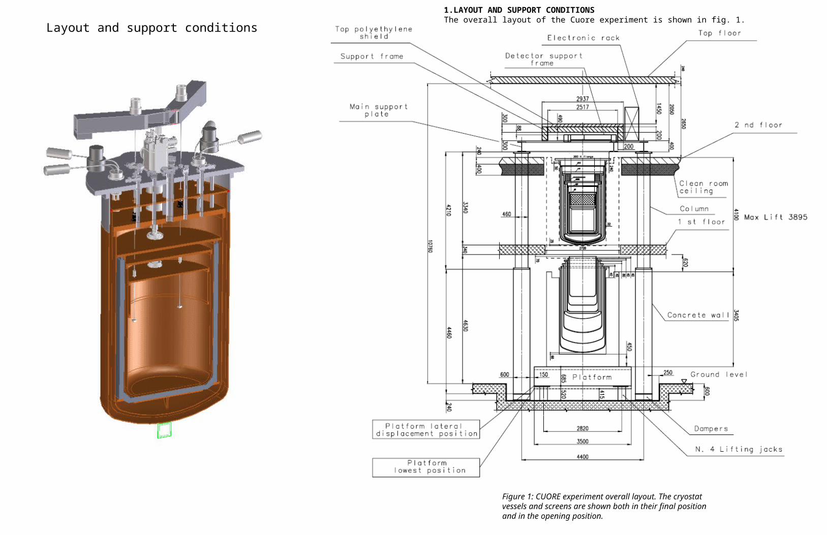
1.LAYOUT AND SUPPORT CONDITIONSThe overall layout of the Cuore experiment is shown in fig. 1.
Figure 1: CUORE experiment overall layout. The cryostat vessels and screens are shown both in their final position and in the opening position.
Layout and support conditions

1.LAYOUT AND SUPPORT CONDITIONSThe overall layout of the Cuore experiment is shown in fig. 1.
Figure 1: CUORE experiment overall layout. The cryostat vessels and screens are shown both in their final position and in the opening position.
Layout and support conditions

SCENARIO 1 Initial installation
ACTIVITY 1.1 Initial cryostat setup
Sequential tasks Detailed procedureTools, prerequisites
and notes
1.1.1 Installation of 300K flange
Lift up the 300K flange from the ground floor and connect the three supports to the MSP, leveling
SMP + additional platform, CLS. Access to the MSP top
1.1.2 Installation of 40K plate
Install the three first segments of the STILL shield suspension rods on the 300K flange, lift up the 40K flange from the ground floor and connect the three suspension rods
SMP + additional platform, CLS.
1.1.4 Installation of the 4k flange
Install the three second segments of the STILL shield suspension rods on the 40K plate, lift up the 4K flange from the ground floor and connect the three suspension rods. Connect the vacuum feedthroughs of the suspension rods to the 4K flange
SMP + additional platform, CLS.
1.1.5 Installation of the STILL plate
Install the three third segments of the STILL shield suspension rods on the 4K flange, lift up the STILL plate from the ground floor and connect the three suspension rods
SMP + additional platform, CLS.
1.1.6 Installation of the HEX plate
Install the three tie rods on the STILL plate, lift up the HEX plate from the ground floor and connect the three tie rods
SMP + additional platform, CLS.
1.1.7 Installation of the MC plate
Install the three tie rods on the HEX plate, lift up the MC plate from the ground floor and connect the three tie rods
SMP + additional platform, CLS.
Scenario 1.1 Initial installation

SCENARIO 1 Initial installation
ACTIVITY 1.2dry assembly of the cryostat vessels/screens (check procedure, clearances and all related mechanical issues, commissioning of handling tools)
Sequential tasks Detailed procedureTools, prerequisites
and notes
1.2.1 Installation of the MC top screen segment
Set the MC top screen segment on the SMP, install the lifting collars, lift it up and fix it to the MC plate, remove the collars
SMP, CLS
1.2.2 Installation of the MC dummy screen
Set the MC dummy screen on the SMP, install the lifting collars, lift it up and fix it to the MC screen top segment, remove the collars
SMP, CLS
1.2.3 Installation of the HEX screen
Set the HEX screen on the SMP, install the lifting collars, lift up and fix it to the HEX plate, remove the collars
SMP, CLS
1.2.4 Installation of the STILL screen
Set the STILL screen on the SMP, install the lifting collars, lift up and fix it to the STILL plate, remove the collars
SMP, CLS. Note that the STILL shield support structure is not installed
1.2.5 Installation of the 4K vessel
Set the 4K vessel on the SMP, install the lifting collars, lift up and fix it to the 4K flange, remove the collars
SMP, CLS.
1.2.6 Installation of the 40K screen
Set the 40K screen on the SMP, install the lifting collars, lift up and fix it to the 40K plate, remove the collars
SMP, CLS
1.2.7 Installation of the 300K vessel
Set the 300K vessel on the SMP, install the lifting collars, lift up and fix it to the 300K flange, remove the collars
SMP, CLS.
Scenario 1.2 Initial installation cont’d
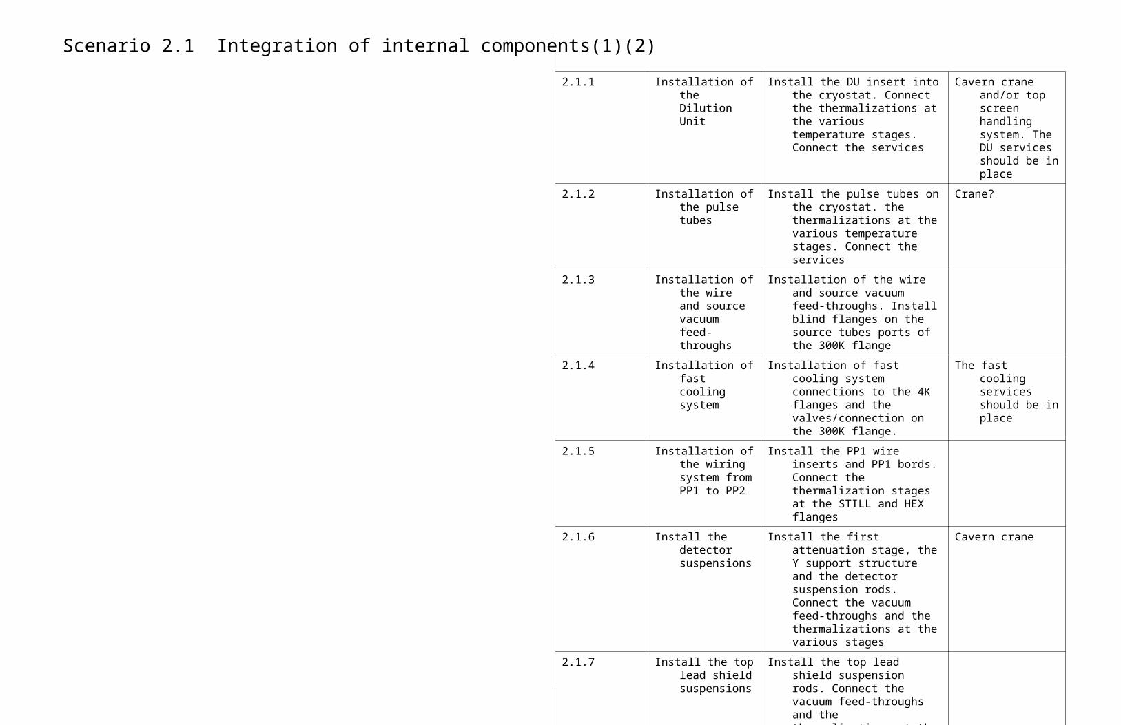
Scenario 2.1 Integration of internal components(1)(2)
2.1.1 Installation of the Dilution Unit
Install the DU insert into the cryostat. Connect the thermalizations at the various temperature stages. Connect the services
Cavern crane and/or top screen handling system. The DU services should be in place
2.1.2 Installation of the pulse tubes
Install the pulse tubes on the cryostat. the thermalizations at the various temperature stages. Connect the services
Crane?
2.1.3 Installation of the wire and source vacuum feed-throughs
Installation of the wire and source vacuum feed-throughs. Install blind flanges on the source tubes ports of the 300K flange
2.1.4 Installation of fast cooling system
Installation of fast cooling system connections to the 4K flanges and the valves/connection on the 300K flange.
The fast cooling services should be in place
2.1.5 Installation of the wiring system from PP1 to PP2
Install the PP1 wire inserts and PP1 bords. Connect the thermalization stages at the STILL and HEX flanges
2.1.6 Install the detector suspensions
Install the first attenuation stage, the Y support structure and the detector suspension rods. Connect the vacuum feed-throughs and the thermalizations at the various stages
Cavern crane
2.1.7 Install the top lead shield suspensions
Install the top lead shield suspension rods. Connect the vacuum feed-throughs and the thermalizations at the various stages
2.1.8 (3) Install the STILL lead shield suspensions
Install the STILL lead shield suspension rods. Connect the vacuum feed-throughs and the thermalizations at the various stages
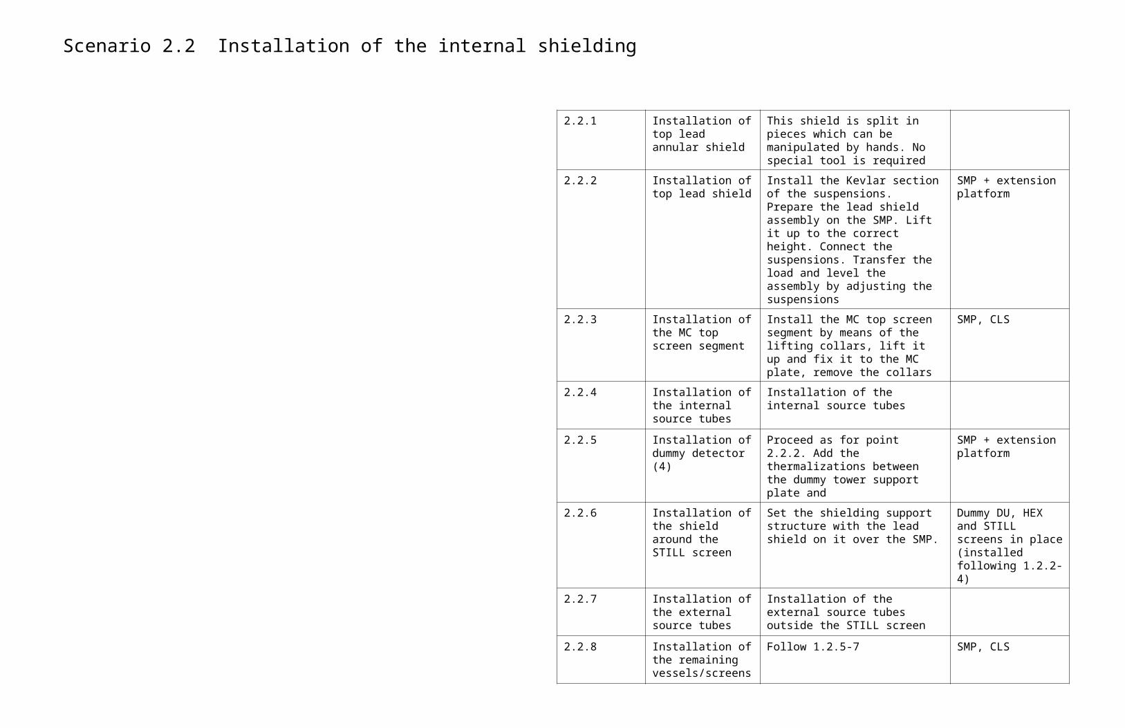
Scenario 2.2 Installation of the internal shielding
2.2.1 Installation of top lead annular shield
This shield is split in pieces which can be manipulated by hands. No special tool is required
2.2.2 Installation of top lead shield
Install the Kevlar section of the suspensions. Prepare the lead shield assembly on the SMP. Lift it up to the correct height. Connect the suspensions. Transfer the load and level the assembly by adjusting the suspensions
SMP + extension platform
2.2.3 Installation of the MC top screen segment
Install the MC top screen segment by means of the lifting collars, lift it up and fix it to the MC plate, remove the collars
SMP, CLS
2.2.4 Installation of the internal source tubes
Installation of the internal source tubes
2.2.5 Installation of dummy detector (4)
Proceed as for point 2.2.2. Add the thermalizations between the dummy tower support plate and
SMP + extension platform
2.2.6 Installation of the shield around the STILL screen
Set the shielding support structure with the lead shield on it over the SMP.
Dummy DU, HEX and STILL screens in place (installed following 1.2.2-4)
2.2.7 Installation of the external source tubes
Installation of the external source tubes outside the STILL screen
2.2.8 Installation of the remaining vessels/screens
Follow 1.2.5-7 SMP, CLS
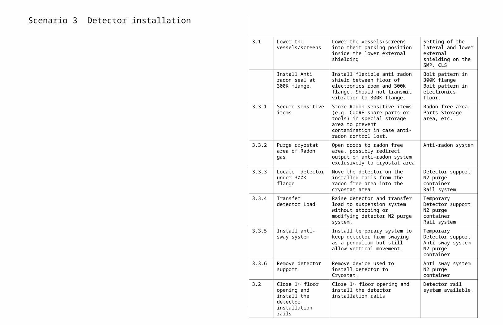
Scenario 3 Detector installation
3.1 Lower the vessels/screens
Lower the vessels/screens into their parking position inside the lower external shielding
Setting of the lateral and lower external shielding on the SMP. CLS
Install Anti radon seal at 300K flange.
Install flexible anti radon shield between floor of electronics room and 300K flange. Should not transmit vibration to 300K flange.
Bolt pattern in 300K flangeBolt pattern in electronics floor.
3.3.1 Secure sensitive items. Store Radon sensitive items (e.g. CUORE spare parts or tools) in special storage area to prevent contamination in case anti-radon control lost.
Radon free area, Parts Storage area, etc.
3.3.2 Purge cryostat area of Radon gas
Open doors to radon free area, possibly redirect output of anti-radon system exclusively to cryostat area
Anti-radon system
3.3.3 Locate detector under 300K flange
Move the detector on the installed rails from the radon free area into the cryostat area
Detector support N2 purge containerRail system
3.3.4 Transfer detector Load Raise detector and transfer load to suspension system without stopping or modifying detector N2 purge system.
Temporary Detector support N2 purge containerRail system
3.3.5 Install anti-sway system Install temporary system to keep detector from swaying as a pendulium but still allow vertical movement.
Temporary Detector support Anti sway systemN2 purge container
3.3.6 Remove detector support
Remove device used to install detector to Cryostat.
Anti sway systemN2 purge container
3.2 Close 1st floor opening and install the detector installation rails
Close 1st floor opening and install the detector installation rails
Detector rail system available.

Scenario 3 Detector installation Cont’d
3.3.7 Check calibration system
Visual check to make sure calibration system tubes line up properly
Anti sway systemN2 purge containerTool(?) to validate
calibration system ok.
3.3.8 Attach mylar signal tapes
Route mylar signal tapes to connections at 4K flange.
Anti sway systemN2 purge container
3.3.9 QA/QC tests on signal/heater connectios
Use device to make sure that signal and heater connections are properly made.
Anti sway systemN2 purge containerContinuous diagnostic
of signal/heater connections during assembly.
3.3.10 QA/QC tests on Calibration system
Perform QA/QC tests on calibration system as needed to verify operational readiness.
Calibration system(How long does this
take given slow motion of calibration system?)
3.3.11 Repair towers? On the basis of QA/QC tests, repair towers or calibration system
See separate repair procedure.

Scenario 4 Install Cryostat vessels and thermal shields
4.1
Purge vessels
Purge the volume between the vessels and the temporary floor of the clean room with N2 or radon free air. If N2, must consider oxygen deficiency issues.
Flexible anti-radon barrier between floor and vessels
N2 or radon-free air
4.2 Remove temporary Floor
Remove the temporary floor after the volume below has been purged.
Tools to remove radon seal around temporary floor and place to store floor
4.3 Remove N2 shield around detector
Remove the N2 shield around the detector
Tools to remove N2 shield
4.4 Raise 10mK shield Use lifting platform to install 10mK shield and attach to cold plate.
Lifting platform Vessel hoist system
4.5 Raise HEX shield Use lifting platform to install ~50mK shield and attach to ??
Lifting platformVessel hoist system
4.6 Flush HeX shield with N2
Use tube starting from 4K flange that goes through ~ 50mk shield to flush detector with N2 gas. Gas flow can be removed after 4k IVC installed and pumped down.
Need special ~6mm dia tube to flush 50mK shield with N2. Should attach to 4K flange to avoid interference during installation of other shields.
Is there a problem with the heat load on the detector if this N2 line is installed ?(it will be permanent)
4.7 Install Still Shield Install Still shield using platform and hoist.
Hoists and platform
4.8 Perform QA/QC electrical/electronic systems
Perform electrical tests on detector. Automatic debugging device to insure signal continuity.

Scenario 4 Install Cryostat vessels and thermal shields Cont’d
4.9 Perform QA/QC tests on calibration system.
Perform QA/QC tests on calibration system to insure integrity of system.
Assumes DCS is operational, and can move sources quickly for debug testing.
4.10 Reinstall temporary floor in clean room and seal
Install the temporary floor in the clean room in preparation to change the platform & vessels below.
N.B.: temporary floor cannot be supported by vessels below, other wise cannot maintain anti-radon seal.
Temporary floor
4.11 Remove anti-radon flexible accordion shield
Disconnect the flexible anti-radon shield below the clean room floor. Should store with vessels.
Tools, access to bottom of clean room floor to remove fasteners.
4.12 remove vessel platform Move the vessel platform to the side in preparation for main platform with remaining shields and Pb shield.
2nd rail system for vessel platform
4.13 Install main platform Move main lifting platform with remaining vessels into place under cryostat.
Main lifting platform
4.14 Install accordion radon barrier
Install flexiable accordion radon barrier between clean room floor and top of Pb shield.
Flexible anti radon barrier.
Access to fasteners at bottom of clean room floor.
4.15 Purge volume below floor
Purge the volume below the floor with N2 gas or Radon free air.
N2 purge or Radon free air supply
4.16 Remove temporary floor
Remove radon seal and temporary floor in clean room above vessels.
Space to store temporary floor
4.17 Install 4K shield Use platform and hoists to raise 4k vessel
Lifting platfrorm and hoists.
4.18 Stop N2 flow to detector
Stop N2 flow to detector and pull vacuum on 4K vessel for vacuum test AND to protect detector from radon
Can 4k IVC be pumped down with air on the outside, vacuum on the inside?
Lifting platform, hoists, vacuum system.
Assumes we can pump on the 4k shield during installation w/o safety issues.
4.19 Install 40K shield Use hoists and platform to install 40K shield.
Assumes we can pump on the 4k shield during installation w/o safety issues.

Scenario 4 Install Cryostat vessels and thermal shields Cont’d
4.20 Install 300K vessel Use hoists and Platform to install 300K vessel (OVC)
Lifting platform and hoists
Assumes we can continue to pump on the 4k shield during installation w/o safety issues
4.21 QA/QC tests on detector
Repeat QA/QC tests on detector electronics
See separate procedure
4.22 QA/QC tests on DCS Perform QA/QC tests on DCS See separate procedure.
4.23 QA/QC tests on Cryostat
Perform QA/QC tests on Cryostat, including pump down & cooling
See separate procedure.
4.24 Raise ~80T Pb shield Raise 80T Pb shield using lifting jacks See separate procedure.(Is detector pumped
down, or backfilled with N2 for this step?)
4.25 Attach E. Room Faraday cage to external surface of cryostat.
Make connection between Electronics room Faraday cage and Faraday cage on outside of Pb shield. This could be “automatic” when the shield is raised.
Access space at ceiling of clean room to make connection if not “automatic.”
4.26 Create Radon shield at top of detector
Install anti-radon shield at top of detector to limit radon infiltration inside Pb shield during detector operations. N2 or “radon-free” air.
Access space at ceiling of clean room to make connection if not “automatic.”
Potential safety issues with oxygen deficient volume.
4.27 Turn on purge gas Turn on gas to purge inside of Pb shield (N2 or radon free air)
Potential safety issues with oxygen deficient volume.