Embed Size (px)
Citation preview

Assembly Variables: Registers
• Unlike HLL like C or Java, assembly cannot use variables
–Why not? Keep Hardware Simple
• Assembly Operands are registers
–Limited number of special locations built directly into the hardware
–Operations can only be performed on these!
• Benefit: Since registers are directly in hardware, they are very fast

ARM Integer Arithmetic
Instruction Description Example
add<cond><S> rd, rn, op2
Adds the value in rn and the value of op2 and stores result to rd
add r2, r0, r1
adc<cond><S> rd, rn, op2 Adds rn, r2, and carry adc r2, r0, r1
sub<cond><S> rd, rn, op2 Subtracts the value of op2 from the value in rn
sub r2, r0, #50
rsb<cond><S> rd, rn, op2 Subtracts the value in rn from the value of op2
rsb r2, r0, r1

ARM Integer Arithmetic
Instruction Description Example
mul<cond><S> rd, rm, rs Multiplies the values from rm and rs, and places the least signigicant 32 bits of the result in rd
mul r7, r3, r5
smulxy<cond><S> rd, rm, rs
Multiplies 16-bit signed integer from the select4d halves of rm and rs and stores the 32-bit result in rd
mul r7, r3, r5
Replace xy with bb (bottom/bottom bits), bt (bottom/top bits), tb (top/bottom bits), tt(top/top bits)

ARM Load/Store Instructions
Instruction Description Example
mul<cond><S> rd, rm, rs Multiplies the values from rm and rs, and places the least signigicant 32 bits of the result in rd
mul r7, r3, r5
smulxy<cond><S> rd, rm, rs
Multiplies 16-bit signed integer from the select4d halves of rm and rs and stores the 32-bit result in rd
mul r7, r3, r5
Replace xy with bb (bottom/bottom bits), bt (bottom/top bits), tb (top/bottom bits), tt(top/top bits)
ARM Load/Store Instructions
• The ARM is a Load/Store Architecture:
– Does not support memory to memory data processing operations.
– Must move data values into registers before using them.
• This might sound inefficient, but in practice isn’t:
– Load data values from memory into registers.
– Process data in registers using a number of data processing instructions which are not slowed down by memory access.
– Store results from registers out to memory.

ARM Load/Store Instructions
• ARM has three sets of instructions which interact with main memory. These are:
– Single register data transfer (LDR/STR)
– Block data transfer (LDM/STM)
– Single Data Swap (SWP)
• The basic load and store instructions are:
– Load and Store Word or Byte or Halfword
• LDR / STR / LDRB / STRB / LDRH / STRH
• Syntax:
– <LDR|STR>{<cond>}{<size>} Rd, <address>

Single register data transfer
LDR STR Word
LDRB STRB Byte
LDRH STRH Halfword
LDRSB Signed byte load
LDRSH Signed halfword load
• Memory system must support all access sizes
• Syntax:
– LDR{<cond>}{<size>} Rd, <address>
– STR{<cond>}{<size>} Rd, <address>
e.g. LDREQB

Single register data transfer
LDR STR Word
LDRB STRB Byte
LDRH STRH Halfword
LDRSB Signed byte load
LDRSH Signed halfword load
• Memory system must support all access sizes
• Syntax:
– LDR{<cond>}{<size>} Rd, <address>
– STR{<cond>}{<size>} Rd, <address>
e.g. LDREQB

Data Transfer: Memory to Register
• To transfer a word of data, we need to specify two things:
–Register: r0-r15
–Memory address: more difficult
• Think of memory as a single one-dimensional array, so we can address it simply by supplying a pointer to a memory address.
• Other times, we want to be able to offset from this pointer.
Remember: Load FROM memory
Base Register Addressing Modes
• There are many ways in ARM to specify the address; these are called addressing modes.
–A register which contains a pointer to memory
• Example: [r0]
–specifies the memory address pointed to by the value in r0

Data Transfer: Memory to Register
• Load Instruction Syntax:
1 2, [3]
–where
1) operation name
2) register that will receive value
3) register containing pointer to memory
• ARM Instruction Name:
–LDR (meaning Load Register, so 32 bits (one word) are loaded at a time)

Data Transfer: Memory to Register
• Example: LDR r0,[r1]
This instruction will take the pointer in r1, and then load the value from the memory pointed to by this calculated sum into register r0
• Notes:
–r1 is called the base register
Data Flow

Data Transfer: Register to Memory
• Also want to store value from a register into memory
• Store instruction syntax is identical to Load instruction syntax
• MIPS Instruction Name: STR (meaning Store Register, so 32 bits or one word are loaded at a time)
• Example: STR r0,[r1]
This instruction will take the pointer in r1and store the value from register r0 into the memory address pointed to by the calculated sum
Remember: Store INTO Memory
Data Flow

Base Register Addressing Mode
The memory location to be accessed is held in a base register STR r0, [r1] ; Store contents of r0 to location pointed to
; by contents of r1.
LDR r2, [r1] ; Load r2 with contents of memory location
; pointed to by contents of r1.
r1
0x200 Base
Register
Memory
0x5 0x200
r0
0x5 Source
Register
for STR
r2
0x5 Destination
Register
for LDR

Immediate Offset Addressing Mode
• To specify a memory address to copy from, specify two things:
–A register which contains a pointer to memory
–A numerical offset (in bytes)
• The desired memory address is the sum of these two values.
• Example: [r0,#8]
–specifies the memory address pointed to by the value in r0, plus 8 bytes

Immediate Offset Addressing Mode
• Load Instruction Syntax:
opcode rd, [rn, #imm]
–where
opcode - operation name
rd - register that will receive value
rn - register containing pointer to memory
imm - numerical offset in bytes

Immediate Offset Addressing Mode
• Example: LDR r0, [r1,#12] This instruction will take the pointer in r1, add 12 bytes to
it, and then load the value from the memory pointed to by this calculated sum into register r0
• Example: STR r0, [r1,#-8]
This instruction will take the pointer in r0, subtract 8 bytes from it, and then store the value from register r0 into the memory address pointed to by the calculated sum
• Notes: – r1 is called the base register –#constant is called the offset –offset is generally used in accessing elements of array or
structure: base reg points to beginning of array or structure

Immediate Offset Addressing Mode
* Example: STR r0, [r1,#12]
* To store to location 0x1f4 instead use: STR r0, [r1,#-12]
* To auto-increment base pointer to 0x20c use: STR r0, [r1, #12]! (called immediate pre-indexed addressing mode)
* If r2 contains 3, access 0x20c by multiplying this by 4:
• STR r0, [r1, r2, LSL #2] (called scaled register offset addressing mode)
r1
0x200 Base
Register
Memory
0x5
0x200
r0
0x5 Source
Register
for STR Offset
12 0x20c
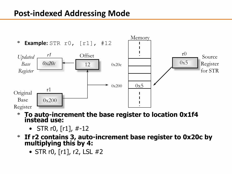
Post-indexed Addressing Mode
* Example: STR r0, [r1], #12
* To auto-increment the base register to location 0x1f4 instead use:
• STR r0, [r1], #-12
* If r2 contains 3, auto-increment base register to 0x20c by multiplying this by 4:
• STR r0, [r1], r2, LSL #2
r1
0x200
Original
Base
Register
Memory
0x5 0x200
r0
0x5 Source
Register
for STR
Offset
12 0x20c
r1
0x20c Updated
Base
Register

Using Addressing Modes Efficiently
* Imagine an array, the first element of which is pointed to by the contents of r0.
* If we want to access a particular element, then we can use pre-indexed addressing:
• r1 is element we want.
• LDR r2, [r0, r1, LSL #2]
* If we want to step through every element of the array, for instance to produce sum of elements in the array, then we can use post-indexed addressing within a loop:
• r1 is address of current element (initially equal to r0).
• LDR r2, [r1], #4
Use a further register to store the address of final element, so that the loop can be correctly terminated.
0
1
2
3
element
0
4
8
12
Memory
Offset
r0
Pointer to start
of array

Pointers vs. Values
• Key Concept: A register can hold any 32-bit value. That value can be a (signed) int, an unsigned int, a pointer (memory address), and so on
• If you write ADD r2,r1,r0 then r0 and r1 must contain values
• If you write LDR r2,[r0] then [r0] must contain a pointer
• Don’t mix these up!

Addressing: Byte vs. word
• Every word in memory has an address, similar to an index in an array
• Early computers numbered words like C numbers elements of an array:
–Memory[0], Memory[1], Memory[2], …
Called the “address” of a word
Computers needed to access 8-bit (byte) as well
as words (4 bytes/word)
Today machines address memory as bytes, hence
32-bit (4 byte) word addresses differ by 4
Memory[0], Memory[4], Memory[8], …

Notes about Memory
• Pitfall: Forgetting that sequential word addresses in machines with byte addressing do not differ by 1.
–Many an assembly language programmer has toiled over errors made by assuming that the address of the next word can be found by incrementing the address in a register by 1 instead of by the word size in bytes.
–So remember that for both LDR and STR, the sum of the base address and the offset must be a multiple of 4 (to be word aligned)

More Notes about Memory: Alignment
0 1 2 3
Aligned
Not
Aligned
• ARM typically requires that all words start at byte addresses that are multiples of 4 bytes
Called Alignment: objects must fall on address
that is multiple of their size.
0, 4, 8, or Chex
Last hex digit
of address is:
1, 5, 9, or Dhex
2, 6, A, or Ehex
3, 7, B, or Fhex

Role of Registers vs. Memory
• What if more variables than registers?
–Compiler tries to keep most frequently used variables in registers
–Less common in memory: spilling
• Why not keep all variables in memory?
–Smaller is faster: registers are faster than memory
–Registers more versatile:
• ARM arithmetic instructions can read 2, operate on them, and write 1 per instruction
• ARM data transfer only read or write 1 operand per instruction, and no operation