Embed Size (px)
Citation preview
Yuan Xue
Vanderbilt University
WISE 2010
Assessing Security of Cyber-Physical Systems

Outline
Introduction
– What is CPS/Example systems
– Security Issues of CPS
Tools/Experiment Environment for CPS Security Assessment
– Run-time: Integration of multiple tools/Environment
Simulation, emulation, real testbed
– Modeling-time, rapid configuration/deployment
Model integration
Step I: Command and Control Wind Tunnel
– Heterogeneous simulation integration
Step II, Integration of DeterLab and C2WT
– Simulation and emulation integration
Step III – Future Directions
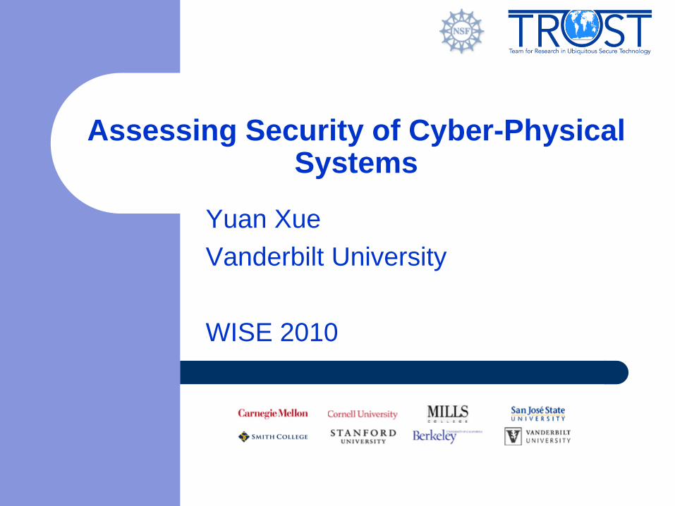
Cyber-Physical Systems
CPS has extraordinary significance for the future of the U.S. industry and military
superiority.
– A 2007 report of the President’s Council of Advisors on Science and Technology
highlights CPS as the number one priority for federal investments in networking
and information technology.
Application Domains
– Health-Care
– Automotive Systems
– Building and Process Controls
– Defense and Aviation Systems
– Critical Infrastructure
Cyber-physical systems (CPS) are tight integrations of
communications, computational and physical processes

Example: Electric Power Grid
Current picture:
– Equipment protection devices trip locally, reactively
– Cascading failure: August (US/Canada) and October (Europe), 2003
Better future?
– Real-time cooperative control of protection devices
– Or -- self-healing -- (re-)aggregate islands of stable bulk power (protection, market motives)
– Ubiquitous green technologies
– Issue: standard operational control concerns exhibit wide-area characteristics (bulk power stability and quality, flow control, fault isolation)
– Technology vectors: FACTS, PMUs
– Context: market (timing?) behavior, power routing transactions, regulation
IT Layer
Images thanks to William H. Sanders, Bruce Krogh, and Marija Ilic
CPS Briefing NSF, May 10, 2007 Raj Rajkumar, Carnegie Mellon University
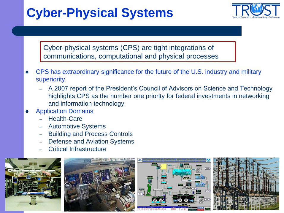
Example: Health Care and Medicine
National Health Information Network, Electronic Patient Record initiative
– Medical records at any point of service
– Hospital, OR, ICU, …, EMT?
Home care: monitoring and control
– Pulse oximeters (oxygen saturation), blood glucose monitors, infusion pumps (insulin), accelerometers (falling, immobility), wearable networks (gait analysis), …
Operating Room of the Future (Goldman)
– Closed loop monitoring and control; multiple treatment stations, plug and play devices; robotic microsurgery (remotely guided?)
– System coordination challenge
Progress in bioinformatics: gene, protein expression; systems biology; disease dynamics, control mechanisms
Images thanks to Dr. Julian Goldman, Dr. Fred Pearce
CPS Briefing NSF, May 10, 2007 Raj Rajkumar, Carnegie Mellon University

CPS Characteristics
Cyber capability in physical component
Size and power of computational elements
Networked at multiple and extreme scales
High degrees of automation, control loops must close at all scales
Enhance and leverage nature physical feedback at all levels
– sensing technology
– actuation technology
Human-System Interaction, human in the control loop
CPS Briefing NSF, May 10, 2007 Raj Rajkumar, Carnegie Mellon University
Security Issues of CPS
Trustworthiness of software and hardware for cyber‐physical
systems is an essential concern since such systems are routinely
employed in critical settings.
Existing systems are built without sufficiently formalized and
analyzed properties and guarantees.
– many existing systems have built‐in vulnerabilities which,
once identified and exploited by attackers, can lead to
catastrophic consequences.
– Most current systems cannot perform any self‐diagnostics to
test whether they have been compromised.
– Even if attacks/intrusions are detected, existing systems
cannot automatically contain, or heal themselves from
consequences of, successful attacks.
7

Core CPS Programmatic Themes
There is a pressing need to design and
evaluate both cyber- and physical systems
(CPS) together and holistically
– Scientific foundations for building verifiably correct
and safe cyber-physical systems
– Scalable infrastructure and components with which
cyber-physical systems can be deployed
– Tools and Experimental Testbed
– Education that encompasses both the cyber and
the physical domains
CPS Briefing NSF, May 10, 2007 Raj Rajkumar, Carnegie Mellon University

Tools for Design & Implementation of CPS
Lyapunov functions,
eigenspace analysis, etc. Analytical Tools
MATLAB, MatrixX,
VisSim, etc., Software Tools
Control Design:
Continuous State
differential equations,
transfer functions, etc. Models
Boolean algebra, formal
logics, recursion, etc.
Statemate, NS-2,
OMNeT++, etc.
Control
Implementation:
Discrete State/Events
automata, Petri nets,
statecharts, etc.

Need for Security Assessment Tool and Experiment Environment
Evaluation of CPS security requires a sophisticated
modeling and simulation, experiment infrastructure
that allows for the concurrent modeling, simulation
and evaluation of
– the CPS system architecture (advanced system-of-systems
modeling)
– running environment (scenario modeling and generation)
– attack scenario (threat modeling and generation).
This requires the integration at two levels
– Run-time: Integration of multiple tools/Environment
Simulation, emulation, real testbed so that they can
interact in a coordinated way.
– Modeling-time: Model integration
rapid configuration/deployment
10
Our Approach
Step I: Command and Control Wind Tunnel – Heterogeneous simulation integration
Step II, Integration of DeterLab and C2WT – Simulation and emulation integration
Step III – Future Directions
C2 Wind Tunnel
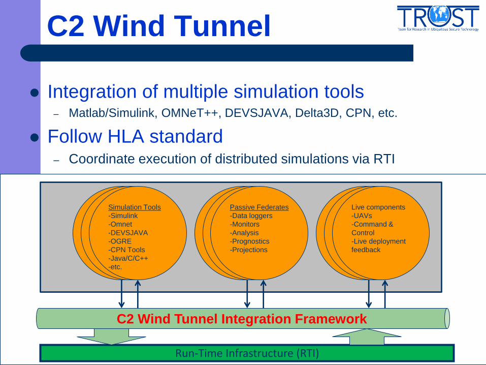
Integration of multiple simulation tools – Matlab/Simulink, OMNeT++, DEVSJAVA, Delta3D, CPN, etc.
Follow HLA standard – Coordinate execution of distributed simulations via RTI
Run-Time Infrastructure (RTI)
C2 Wind Tunnel Integration Framework
Passive Federates
-Data loggers
-Monitors
-Analysis
-Prognostics
-Projections
Live components
-UAVs
-Command &
Control
-Live deployment
feedback
Simulation Tools
-Simulink
-Omnet
-DEVSJAVA
-OGRE
-CPN Tools
-Java/C/C++
-etc.

C2 Wind Tunnel
Model-integrated approach
– Develop an overarching modeling environment based on GME
– Integrate different platform-specific simulation models
Introducing Network Emulation Into C2WT
Motivation to Introduce Network Emulation
Design Consideration and Challenges
Our Approach and Solution – Communication architecture
– Time synchronization
In collaboration with Timothy Busch (AFRL/RISB)

From Simulation to Emulation
Network components and policies are essential aspects of CPS
The impact of network on CPS system need to be accurately
characterized
– Think about the network attacks…
Limit of network simulator
– Protocol implementation details are missing
– Poor scalability
Network simulation is insufficient in providing the level of accuracy
required by the evaluation of CPS.

From Simulation to Emulation
Benefit of network emulation
– Greater realism and accuracy with truthful protocol
implementation and real network traffic delivery
– Providing a computing platform where prototypes of
software components can be deployed
Network emulation platform
– Emulab
– DETERNet
Large number of tools available for emulate network attacks
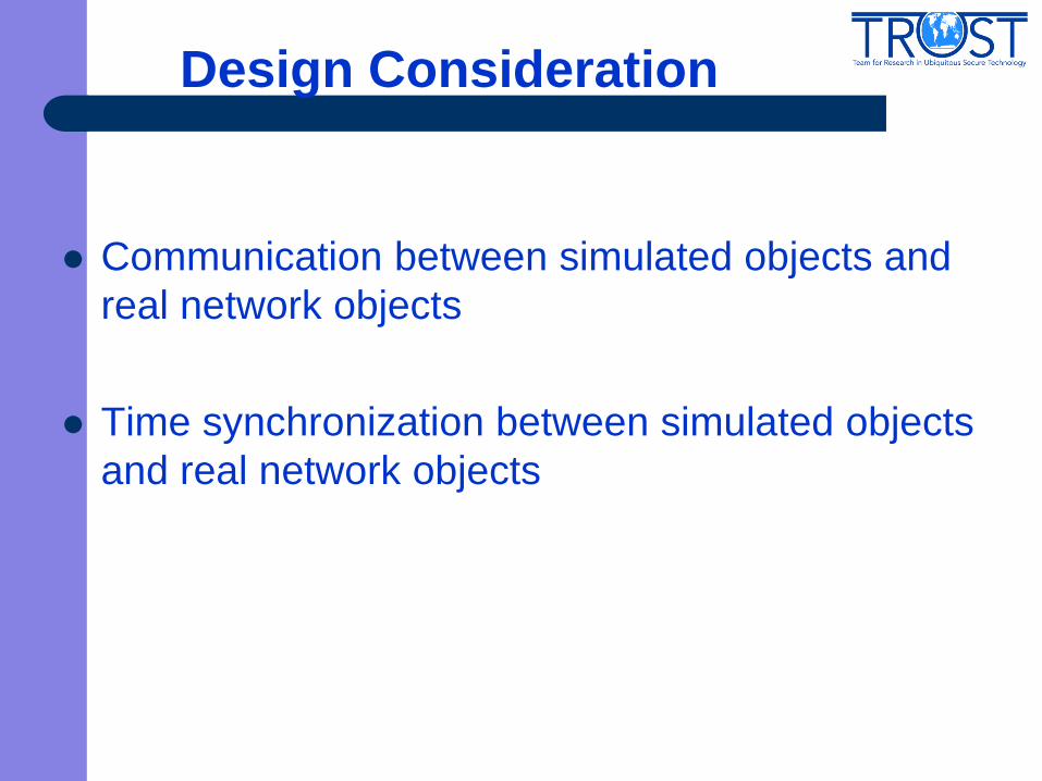
Design Consideration
Communication between simulated objects and
real network objects
Time synchronization between simulated objects
and real network objects

Challenge in Data Communication
Key Issue
– There is potentially large volume of data communicated between the
simulation and the emulation environment
– Tradeoff between realism and performance
– How to control the communication overhead
Approaches
– Identify the communication platform (e.g., RTI, pub/sub service, socket,
etc.)
– Control the application-level messages
– Design efficient transport-level protocols (e.g., reliable multicast)

Challenge in Data Communication
Observation -- Different types of data
– Command/Signal notification (E.g., Start to send, stop to send, change
sending rate)
– Application Data/Payload (E.g., Images, videos)
Our approach
– Identify the appropriate communication platform for different types of
data
– Define the appropriate granularity of communication data depending on
the application semantics
– Characterize the communication semantics in the modeling phase
Model integration
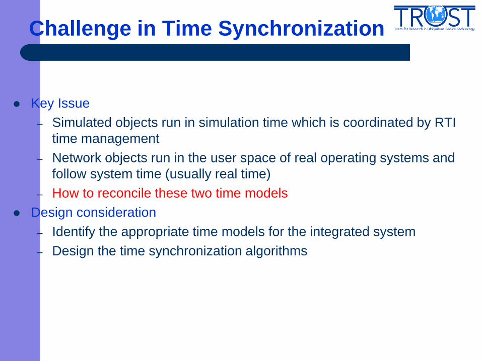
Challenge in Time Synchronization
Key Issue
– Simulated objects run in simulation time which is coordinated by RTI
time management
– Network objects run in the user space of real operating systems and
follow system time (usually real time)
– How to reconcile these two time models
Design consideration
– Identify the appropriate time models for the integrated system
– Design the time synchronization algorithms
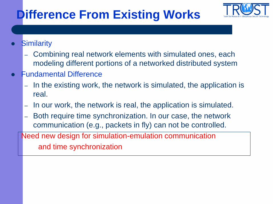
Difference From Existing Works
Similarity
– Combining real network elements with simulated ones, each
modeling different portions of a networked distributed system
Fundamental Difference
– In the existing work, the network is simulated, the application is
real.
– In our work, the network is real, the application is simulated.
– Both require time synchronization. In our case, the network
communication (e.g., packets in fly) can not be controlled.
Need new design for simulation-emulation communication
and time synchronization
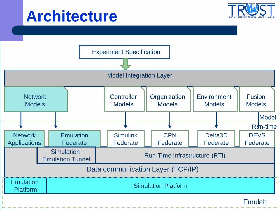
Architecture
Run-Time Infrastructure (RTI)
Model Integration Layer
Experiment Specification
Network
Models
Controller
Models
Organization
Models
Environment
Models
Fusion
Models
Emulation
Federate
Simulink
Federate
CPN
Federate
Delta3D
Federate
DEVS
Federate
Simulation Platform
Simulation-
Emulation Tunnel
Model
Run-time
Network
Applications
Emulation
Platform
Emulab
Data communication Layer (TCP/IP)

Pros and Cons
Pros
– Limit the traffic load of RTI
The communication between simulated objects and real
objects does not go through RTI
– Few code changes to simulators
Cons:
– The node that hosts the Emulation Gateway Federate may be
comes a bottleneck
All traffic goes through Emulation Gateway Federate
We may use multiple instances of Emulation Gateway
Federate and perform parallel simulation to solve this
bottleneck issue

Meta-Model and Models
Network Topology Model
Network Application Process Deployment and
Communication Model
Network Interaction Model
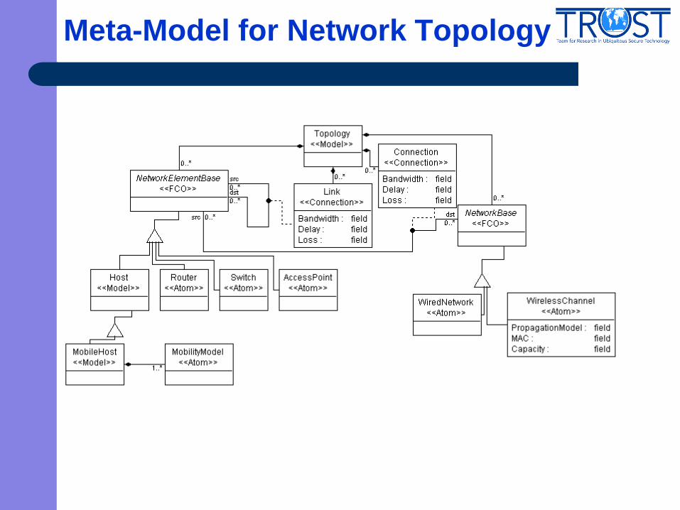
Meta-Model for Network Topology
UAV1
UAV2
Access
Point
Control
Station
11M bps wireless link
11M bps wireless link
10M bps
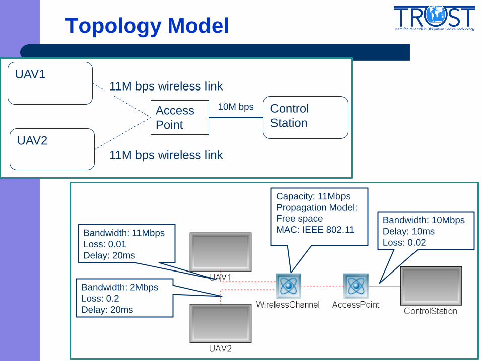
Topology Model
Bandwidth: 10Mbps
Delay: 10ms
Loss: 0.02
Capacity: 11Mbps
Propagation Model:
Free space
MAC: IEEE 802.11
Bandwidth: 2Mbps
Loss: 0.2
Delay: 20ms
Bandwidth: 11Mbps
Loss: 0.01
Delay: 20ms
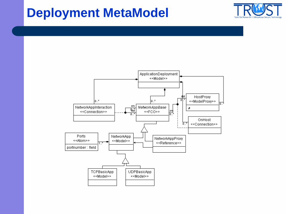
Deployment MetaModel
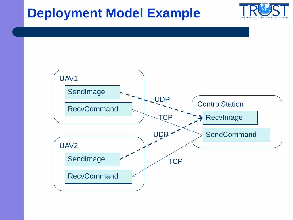
Deployment Model Example
UAV1
SendImage
RecvCommand ControlStation
RecvImage
SendCommand
UAV2
SendImage
RecvCommand
UDP
UDP
TCP
TCP
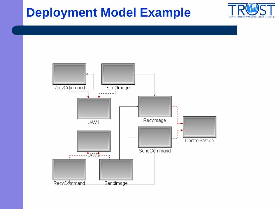
Deployment Model Example
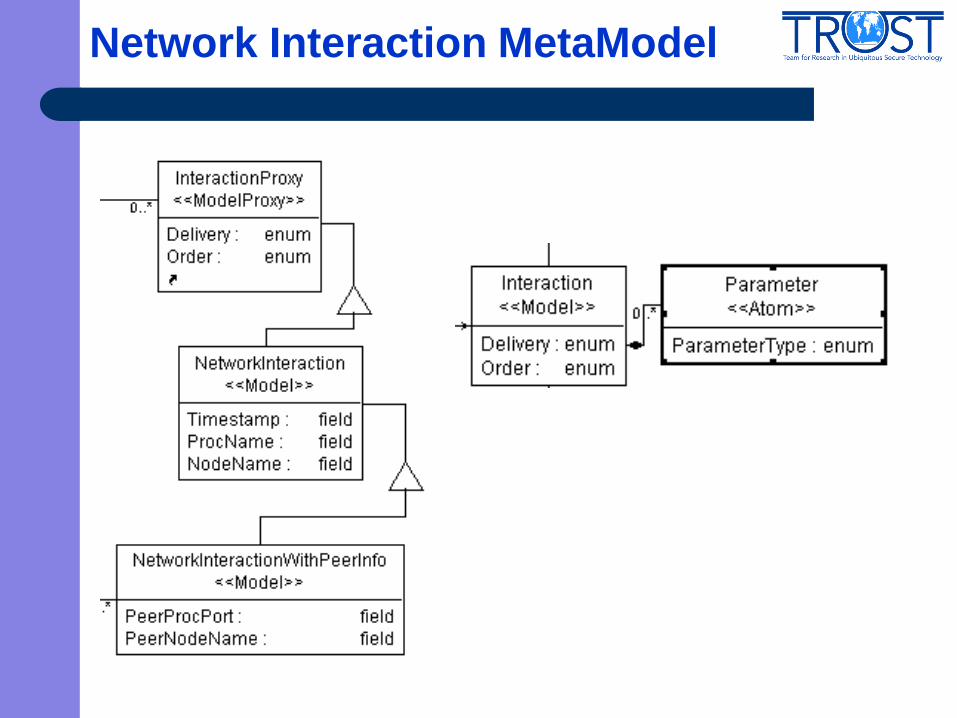
Network Interaction MetaModel
Network Interaction Model Example
Connection-oriented UDP
– Message driven no fixed packet size, interval, starting time
Command: String
Image: URL/real data

SendCommandToNetwork
NodeName: TBD (ControalStation)
ProcName: SendCommand
Timestamp:TBD
Parameter: Command (String)
RecvCommandFromNetwork
NodeName: TBD (UAV1)
ProcName: RecvCommand
Timestamp: TBD
PeerNodeName: TBD (ControlStation)
PeerProcPort: TBD
Parameter: Command (String)
SendImageToNetwork
NodeName: TBD (UAV1)
ProcName: SendImage
Timestamp: TBD
Parameter: ImageURL (String):
RecvImageFromNetwork
NodeName: TBD (ControlStation)
ProcName: RecvImage
Timestamp: TBD
PeerNodeName: TBD (UAV 1)
PeerProcPort:TBD
Parameter: PacketDelay(double)

Network Interaction Model More Examples
Case II -- Connection-oriented UDP
– Parameterized UDP
Parameter: frame size, frame interval
Case III – Connectionless UDP
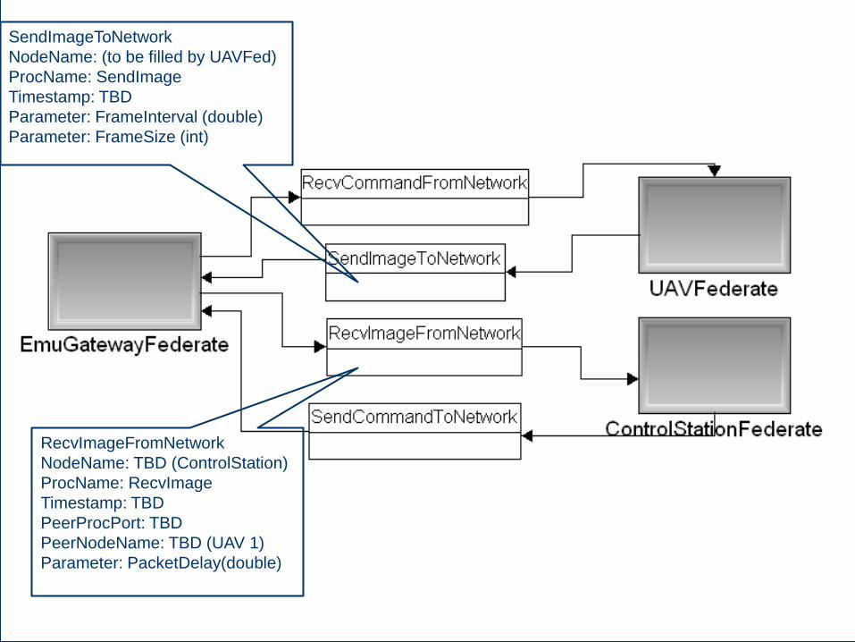
SendImageToNetwork
NodeName: (to be filled by UAVFed)
ProcName: SendImage
Timestamp: TBD
Parameter: FrameInterval (double)
Parameter: FrameSize (int)
RecvImageFromNetwork
NodeName: TBD (ControlStation)
ProcName: RecvImage
Timestamp: TBD
PeerProcPort: TBD
PeerNodeName: TBD (UAV 1)
Parameter: PacketDelay(double)

SendImageToNetwork
NodeName: TBD (UAV1)
ProcName: SendImage
Timestamp: TBD
PeerProcPort: 7890
PeerNodeName: TBD
(ControlStation)
Parameter: FrameInterval (double)
Parameter: FrameSize (int)
RecvImageFromNetwork
NodeName: TBD (ControlStation)
ProcName: RecvImage
Timestamp: TBD
PeerProcPort: TBD
PeerNodeName: TBD (UAV 1)
Parameter: PacketDelay(double)

Time Synchronization Overview
Time Synchronization
– Simulated objects run in simulation time which is coordinated by RTI
time management
– Network objects run in the user space of real operating systems and
follow system time (usually real time)
– How to reconcile these two time models
Roadmap
– Review basic concepts
– Identify the appropriate time models for the integrated system
Real time
As fast as possible
– Design the time synchronization algorithms
Let’s first review the basics…
Slides are adapted from Dr. Fujimoto’s lecture notes

Time Models in Simulation
Continuous time simulation
– State changes occur continuously across time
– Typically, behavior described by differential equations
Discrete time simulation
– State changes only occur at discrete time instants
– Time stepped: time advances by fixed time increments
– Event stepped: time advances occur with irregular increments
computer
simulation
discrete
models
continuous
models
event
driven
time-
stepped
sta
te v
ariable
s
simulation time
event driven execution
sta
te v
ariable
s
simulation time
time stepped execution
c2w
Real system
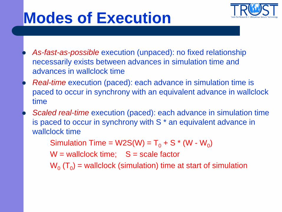
Modes of Execution
As-fast-as-possible execution (unpaced): no fixed relationship
necessarily exists between advances in simulation time and
advances in wallclock time
Real-time execution (paced): each advance in simulation time is
paced to occur in synchrony with an equivalent advance in wallclock
time
Scaled real-time execution (paced): each advance in simulation time
is paced to occur in synchrony with S * an equivalent advance in
wallclock time
Simulation Time = W2S(W) = T0 + S * (W - W0)
W = wallclock time; S = scale factor
W0 (T0) = wallclock (simulation) time at start of simulation
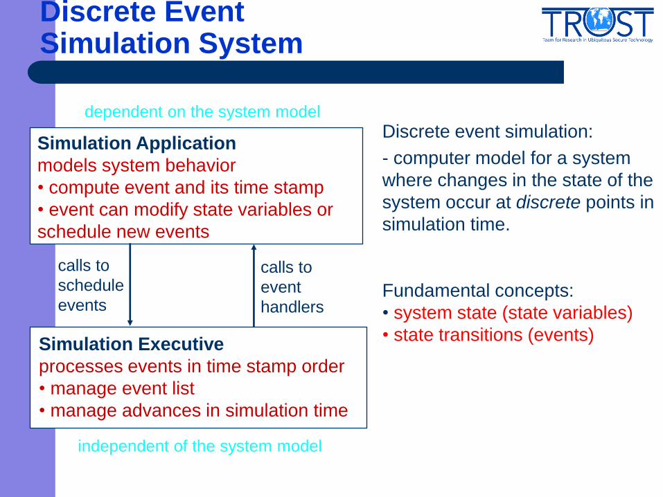
Simulation Application
models system behavior
• compute event and its time stamp
• event can modify state variables or
schedule new events
Simulation Executive
processes events in time stamp order
• manage event list
• manage advances in simulation time
calls to
schedule
events
calls to
event
handlers
Discrete Event Simulation System
independent of the system model
Discrete event simulation:
- computer model for a system
where changes in the state of the
system occur at discrete points in
simulation time.
Fundamental concepts:
• system state (state variables)
• state transitions (events)
dependent on the system model

Parallel/Distributed Discrete Event Simulation
Encapsulate each simulator in a logical process (LP)
LP is capable of concurrent execution
Logical processes can schedule events for other logical processes
– Interactions via message passing
– No shared state variables
logical
process ORD
SFO JFK
arrival
10:00
time stamped event
(message)
Example: model a network of airports
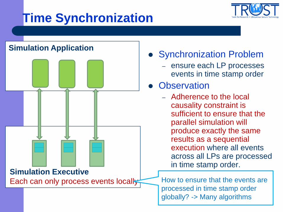
Time Synchronization
Synchronization Problem – ensure each LP processes
events in time stamp order
Observation – Adherence to the local
causality constraint is sufficient to ensure that the parallel simulation will produce exactly the same results as a sequential execution where all events across all LPs are processed in time stamp order.
Simulation Application
Simulation Executive
Each can only process events locally
How to ensure that the events are
processed in time stamp order
globally? -> Many algorithms
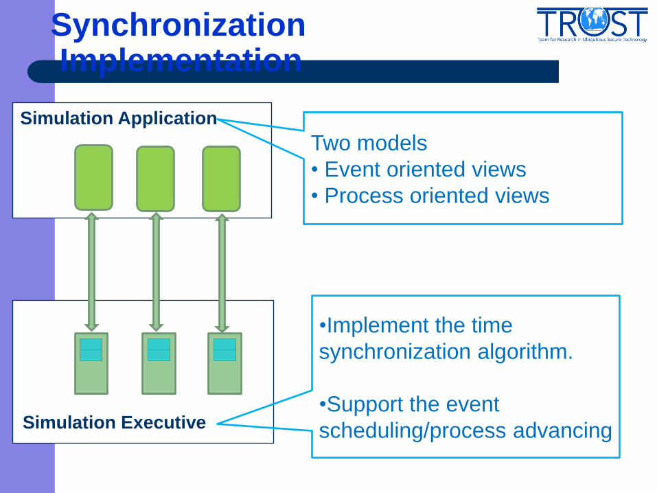
Synchronization Implementation
Simulation Application
Simulation Executive
•Implement the time
synchronization algorithm.
•Support the event
scheduling/process advancing
Two models
• Event oriented views
• Process oriented views

Event vs. Process Oriented Views
1 InTheAir := InTheAir + 1;
2 WaitUntil (RunwayFree); /* circle */
3 RunwayFree := FALSE; /* land */
4 AdvanceTime(R);
5 RunwayFree := TRUE;
/* simulate aircraft on the ground */
6 InTheAir := InTheAir - 1;
7 OnTheGround := OnTheGround + 1;
8 AdvanceTime(G);
/* simulate aircraft departure */
9 OnTheGround := OnTheGround – 1;
State variables
Integer: InTheAir;
Integer: OnTheGround;
Boolean: RunwayFree;
Event oriented view
Entities modeled by event handlers
State variables
Integer: InTheAir;
Integer: OnTheGround;
Boolean: RunwayFree;
Process oriented view
Entities modeled by processes
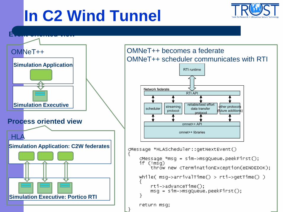
In C2 Wind Tunnel Event oriented view
Process oriented view
Simulation Application
Simulation Executive
HLA
OMNeT++
Simulation Application: C2W federates
Simulation Executive: Portico RTI
OMNeT++ becomes a federate
OMNeT++ scheduler communicates with RTI

Time Management in C2 Wind Tunnel
Simulation Application: C2W federates
Simulation Executive: Portico RTI
Two Modes:
• real time
• as fast as possible
In Federation Manager:
sleep_time = time_diff
if (sleep_time >0)
sleep(sleep_time);
next_time = time.getTime() + 0.1;
timeAdvanceRequest (next_time);
HLA Time management
•Time AdvanceRequest
(time-stepped mechanism)
•NextEvent Request
•(event-driven federate)
•AdvanceGrant
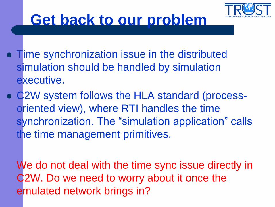
Get back to our problem
Time synchronization issue in the distributed
simulation should be handled by simulation
executive.
C2W system follows the HLA standard (process-
oriented view), where RTI handles the time
synchronization. The “simulation application” calls
the time management primitives.
We do not deal with the time sync issue directly in
C2W. Do we need to worry about it once the
emulated network brings in?
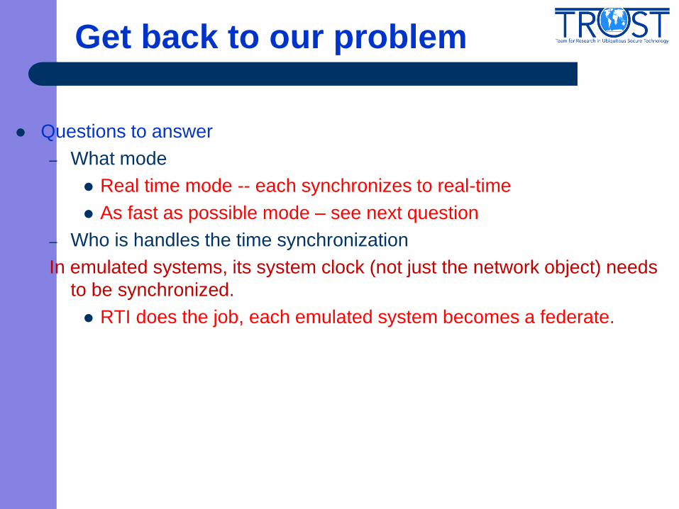
Get back to our problem
Questions to answer
– What mode
Real time mode -- each synchronizes to real-time
As fast as possible mode – see next question
– Who is handles the time synchronization
In emulated systems, its system clock (not just the network object) needs
to be synchronized.
RTI does the job, each emulated system becomes a federate.
Time Synchronization Real Time Mode
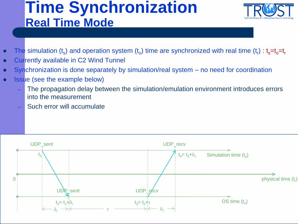
The simulation (ts) and operation system (to) time are synchronized with real time (tr) : ts=to=tr
Currently available in C2 Wind Tunnel
Synchronization is done separately by simulation/real system – no need for coordination
Issue (see the example below)
– The propagation delay between the simulation/emulation environment introduces errors
into the measurement
– Such error will accumulate
0 physical time (tr)
OS time (to)
Simulation time (ts) t1
UDP_sent
t2= t1+d1
UDP_sent
t3= t2+t
UDP_recv
t4= t3+d2
UDP_recv
d2 t d1
Synchronize To Real Time -- Challenge
Since simulation will receive events from emulation, simulation time
should lag behind or equal to emulation time so that the events from
emulation will not arrive at simulation in its past time
Since emulation will receive events from simulation, simulation time
should lead or equal to emulation, so that the events from simulation will
not arrive at emulation in its past time
Without delay, simulation and emulation should be synchronized to the
same time
With delay in both directions, this is a non-trial issue.

Synchronize To Real Time Basic Idea
Synchronize only OS time with real time (to=tr)
Separate simulation time from real time The simulation environment should have at least a lag of (L >= d2) from real time to accommodate the
communication delay emulation to simulation environment, if any incoming traffic is expected. (ts = tr- L)
Simulation clock advances at the same pace as real physical clock
All the outgoing traffic event with time stamp t will be actually scheduled/tunneled to emulation environment at
simulation time t - d1- L to compensate the delay from simulation to emulation and the lag between simulation
and emulation so that it could arrive at emulation at real time t.
For incoming traffic with time stamp (t+t), it will arrive at the simulation at simulation time ts = t-L+t+d2. Since L
d2, the event can be scheduled at ts = t+t
0 Real time (tr)
OS time (to)
Simulation time (ts) ts =t-d1-L
UDP_sent
to =t
UDP_sent
to = t+t
UDP_recv
ts= t+t
UDP_recv
d2 t d1 L
0
ts = t-L+t+d2
Synchronize To Real Time Limitation and Application
The packet does not arrive at the emulated network on its timestamp
time (t), only the measured delay information (t) from the emulation
environment is correctly .
– Can not be used if the packet interacts with other existing traffic this is a
serious constraint.
If the simulation is slower than real time, then there is no easy fix.
So it seems that synchronizing to real time has limited
usage…
Not really. Depending on the value of L (d), the system may
tolerate some inaccuracy.
• Using a model-based approach, the simulator could adjust its time
management strategy based on the communication context
Time Synchronization As Fast As Possible Mode
The simulation (ts) and operation system (to) time
are synchronized using a virtual clock(tv) : ts=to=tv
Currently in C2 Wind Tunnel simulation AFAP
mode runs in virtual time
Challenge-- Reconcile two time models – Real time, which flows naturally (not forced by a progression of
events)
– Virtual time is adjusted by the progression of discrete events in the
simulation system
Synchronize To Virtual Time System Virtualization
Need virtualization of the real systems/networks to control over their run-
time behavior
– The execution of a virtual system/network needs to be stalled until
the virtual clock proceeds
– As the system execution is interrupted due to the synchronization
process, the internal clocks need to be manipulated to provide the
virtual system/network a consistent and continuous time.
Use Xen Hypervisor
– Thin layer between system hardware and the operating system
– Facilitate the parallel execution
– Control the running behavior of OS on top of it
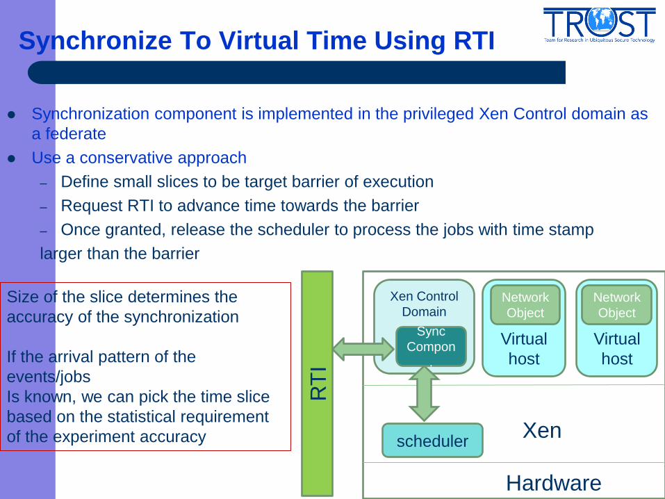
Synchronize To Virtual Time Using RTI
Synchronization component is implemented in the privileged Xen Control domain as
a federate
Use a conservative approach
– Define small slices to be target barrier of execution
– Request RTI to advance time towards the barrier
– Once granted, release the scheduler to process the jobs with time stamp
larger than the barrier
Xen
Hardware
Xen Control
Domain
RT
I
Virtual
host
scheduler
Virtual
host
Network
Object
Network
Object
Sync
Compon
.
Size of the slice determines the
accuracy of the synchronization
If the arrival pattern of the
events/jobs
Is known, we can pick the time slice
based on the statistical requirement
of the experiment accuracy
Handling Packet in Transmission
• Key Issue: Packet can not be stopped in the middle of the transmission or
accelerated to meet the synchronized time
A closer look of the problem – what does it mean by “in the middle”
– Packet queued at a router. In Emulab, the routers are emulated by
host. Queued packets are synchronized to virtual clock not a
problem
– Packet transmitted along the link .The link delay of a packet is
determined by its size and the bandwidth of the link this is a true
problem
If arrive ahead of time, the real time propagation delay needs to be
converted to virtual time and the packet reception will be scheduled later
need a time keeping mechanism
If arrive behind the time, then there will be an issue. We need to adjust the
bandwidth of the link (in Emulab ) to avoid this problem
Implementation Details
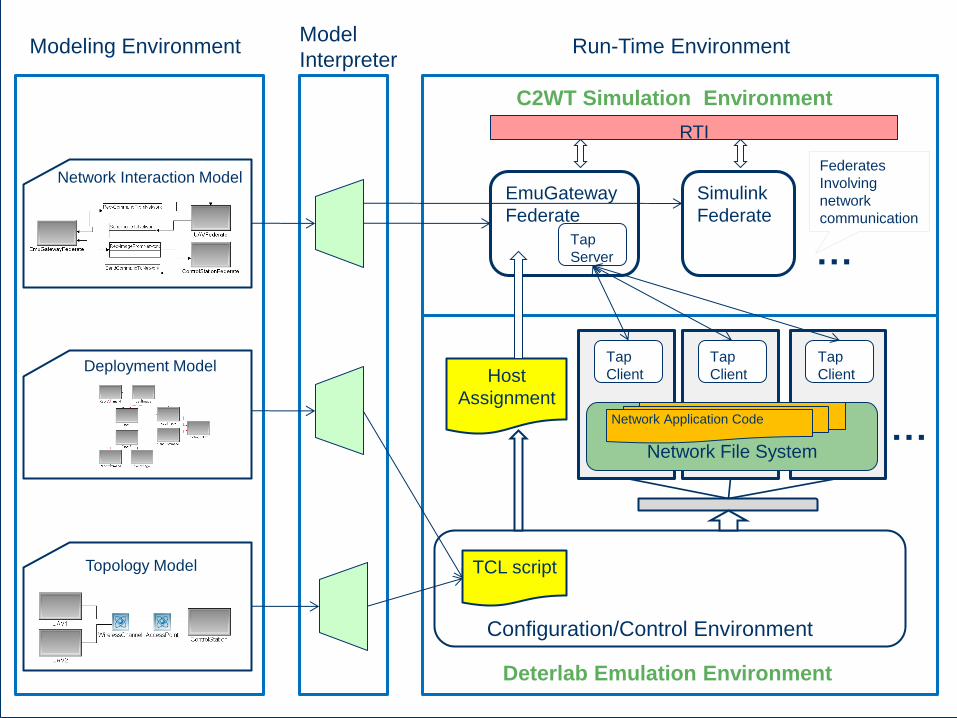
Topology Model
Network Interaction Model
Modeling Environment Model
Interpreter Run-Time Environment
TCL script
Configuration/Control Environment
Host
Assignment
Deterlab Emulation Environment
C2WT Simulation Environment
…
Tap
Client
EmuGateway
Federate
RTI
Simulink
Federate
Tap
Client
Tap
Client
Tap
Server
Federates
Involving
network
communication
…
Network File System
Network Application Code
Deployment Model
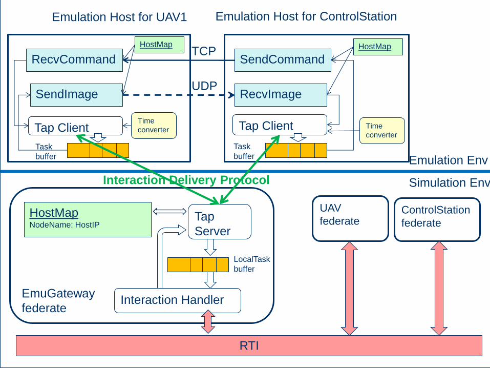
UAV
federate ControlStation
federate
EmuGateway
federate
Tap Client Tap Client
Tap
Server
HostMap NodeName: HostIP
SendImage RecvImage UDP
Emulation Host for UAV1
Interaction Delivery Protocol
Emulation Host for ControlStation
RecvCommand SendCommand TCP
Task
buffer
Task
buffer
LocalTask
buffer
Interaction Handler
Emulation Env
Simulation Env
Time
converter
RTI
Time
converter
HostMap HostMap
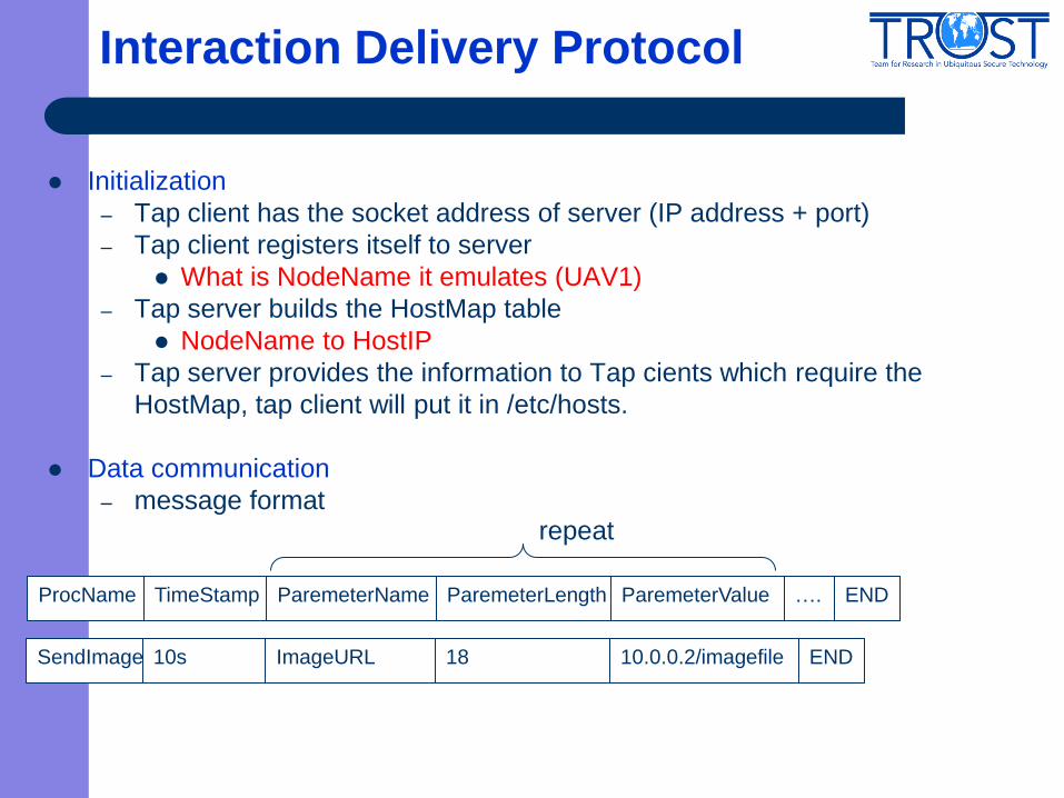
Interaction Delivery Protocol
Initialization
– Tap client has the socket address of server (IP address + port)
– Tap client registers itself to server
What is NodeName it emulates (UAV1)
– Tap server builds the HostMap table
NodeName to HostIP
– Tap server provides the information to Tap cients which require the
HostMap, tap client will put it in /etc/hosts.
Data communication
– message format
ProcName TimeStamp ParemeterName ParemeterLength ParemeterValue
repeat
…. END
SendImage 10s ImageURL 18 10.0.0.2/imagefile
END
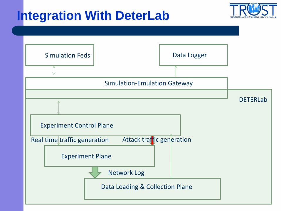
Integration With DeterLab
Simulation Feds
DETERLab
Experiment Control Plane
Experiment Plane
Real time traffic generation
Data Loading & Collection Plane
Network Log
Data Logger
Attack traffic generation
Simulation-Emulation Gateway
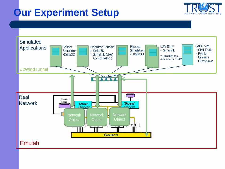
Our Experiment Setup
100Mbps Switch
UAV Sim* • Simulink
Physics Simulation • Delta3D
CAOC Sim. • CPN Tools • Pythia • Caesars • DEVS/Java
Operator Console • Delta3D • Simulink (UAV
Control Algo.)
Sensor Simulator •Delta3D
* Possibly one machine per UAV
C2WindTunnel
Simulated
Applications
Emulab
Network
Object
Network
Object Network
Object
Real
Network
Future Work
Step II: Integration with DeterLab
– Enable system virtualization, migrate the virtual clock
into Xen Hypervisor
– Component allocation
– Time keeping at the emulated routers
Step III: Integration with Experiment Testbed
– Evaluation of security policy on C2 systems
Summary
Security of CPS is an essential concern
Building a tool and environment for assessing the security impacts
on CPS is a critical step
Three-step effort at Vanderbilt
– Simulation integration
– Emulation integration
– Real network integration