Embed Size (px)
Citation preview

BUILDING CONSTRUCTION INFORMATION FROM THE CONCRETE AND MASONRY INDUSIRIES
August 1994
ASSESSING THE CONDITION AND REPAIR
AND MASONRY MEMBERS ALTERNATIVES OF FIRE-EXPOSED CONCRETE
After a building fire, concrete and masonry members may be all that remains. An accurate assessment of the damage is essential to the restoration process
INTRODUCTION When a building is damaged by fire, an inspection to assess the structural damage should be conducted as soon as possible after the fire. With concrete and masonry construction, repair options (insitu restoration or removal and reDlacement) versus demolition and
addition, because of the superior inherent fire resis- tance of concrete and masonry materials, insitu repairs can often be utilized rather than resorting to removal and replacement procedures.
Wood-and steel-framed construction do not offer these advantages. In other than small fires, wood framing members are often consumed as fuel, leaving demolition and reconstruction as the only viable alternative. Unprotected structural steel suffers equally destructive consequences. Lightweight steel trusses and bar joists can collapse after just 5-10 minutes of fire exposure.") Steel columns of small cross-sectional area typically possess a fire endurance of no more than 10-20 minutes.i2) Although steel regains strength upon cooling, the amount of recovery is dependent upon the maximum temperature reached within the mate- rial. Members that are severely distorted during a fire will cool in the deformed position making strength gain useless. The result is irreparabie damage to the steel. Fig. 1 shows the yield strength of steel at elevated temperatures as a percentage of the yield strength at 21°C (70°F).
PURPOSE The sections that follow describe an approach for assessing the condition of fire-exposed concrete and masonry building construction. Various testing and analytical methodologies are described and some general information is provided about restoration procedures. Detailed repair techniques are beyond the scope of this report.
INVESTIGATION PROCEDURES Past experience has shown that concrete and masonry possess excellent structural and barrier capabilities, even in severe building fires. Under certain condi- tions, however, concrete and masonry can suffer sionificant distress. ExamDles include: fires involving
rebuilding are feasible alternatives in most cases. In temperatures well above 'those that result from the

TEMPERATURE, OF 70 200 400 600 800 1000 1200 1400
21 200 400 600 760 TEMPERATURE, OC
Fig. 1. Yield strength of hot-rolled structural grade steels at elevated temperatures as a percentage of initial yield strength at 21°C (70°F). Source: Ref. 3.
burning of ordinary combustibles; and, fires involving heavy fuel loads that cause prolonged burning of combustibles while in direct contact with concrete or masonry.
In the aftermath, an assessment of damaged build- ing elements and the formulation of repair plans must be done. Unfortunately, there is no single procedure that applies in every case. The best approach is one that includes considerations of the fire intensity, age of the structure, the importance of the affected areas or members, and the potential savings that may be gained by conducting a detailed in~estigation.(~) Conducting extensive testing is not always prudent, as it may prove more costly than just proceeding with the removal and replacement of a damaged member. A solid under- standing of both structural engineering principles and the effects of fire on building materials is invaluable in the decision making process.
The Preliminary Investigation After data on the structure and fire event have been collected and safe entry to the building has been established, a preliminary investigation should be performed. Conducting the preliminary inspection becomes the single most important factor in evaluat- ing the building’s rehabilitation potential. The goals of this investigation are to provide information on the condition of the structure, the type and severity of the problems in affected areas, the feasibility of rehabili- tating the structure, and the need for conducting a detailed investigation. American Concrete Institute (ACI) Report document 364.1 R, “Guide for Evaluation of Concrete Structures Prior to Rehabilitati~n,”(~) is a good source document for guidance on conducting both preliminary and detailed investigations of concrete structures.
The first phase of the preliminary investigation is to inspect the structural elements in affected areas for physical appearance. Observations of cracking, spalling, deflections, distortions, misalignment, and exposed steel reinforcement should be noted. Various measu re me n t s of geometry, deflect ions, deformations, etc., can be taken of suspect members for comparison against undamaged members of the same structure. During the investigation, it is useful to document and categorize the type of damage and its severity by building element such as beams, slabs, col- umns and walls. Having a summarized schedule of damage allows for a broader picture of damaged mem- bers in need of a more detailed investigation, and is helpful in evaluating the extent and nature of the repair process. Table 1 provides guidance for assessing and categorizing damage of individual concrete members.
Types of Distress Excessive deflection, large extensive cracks in struc- turally sensitive areas, misalignments, and distorted members are indications that the load-carrying capabilities may have been seriously impaired. Where these types of conditions are present, strong consider- ation should be given to the removal and replacement of affected members. Other factors, however, such as a building’s architectural features and the importance of continuing occupancy can often dictate the selection of the restoration process. If the physical conditions described above are absent, it is likely that concrete and masonry members can be repaired in place.
Concrete Spalled areas of concrete may or may not represent a serious problem, but in any event, can prove to be a useful source of information. In cast-in-place flexural members, local buckling of reinforcing bars exposed by spalling usually indicates that the steel has been subjected to direct fire exposure. As the steel approaches and reaches a temperature of 600°C (1 1 12”F), the bars lose about 50% of their yield strength and are unable to resist the axial thermal restraining forces imposed by the surrounding construction. Thus, buckling occurs.
The absence of buckled or distorted exposed bars in flexural members may indicate that spalling has occurred after the fire. If this is the case, the steel is not likely to have reached 600°C (1 112°F). In general, reinforcing bars in flexural members that lack signs of severe distortion are unlikely to have suffered signifi- cant permanent reduction of yield strength. Similarly, if spalling does not extend to the steel (cover protection remains intact), the structural strength of the member is relatively unaffected.
For columns, the circumstances are different. In columns that contain numerous ties or spiral confine-
2

Table 1. Initial Assessment of Damage and Probable Treatment Required
Damage Class 1 Damage Class 2 Damage Class 3 Damage Class 4 Soot and Smoke
- - deposits Present - 2olor Change - Pink to buff surface Buff surface - Spalling - Only minor Local Extensive Steel exposure - - Steel showing Considerable areas Surface separation Peeling Substantial Surface mostly
gone. Remainder - sounds hollow when struck
Number of main bars buckled - - Not more than one One or more
- - Microcracking - Extensive Distortion Reinforced concrete solid slabs
- - Possible -
Soot and Smoke Present General coverage Completely covered, - deposits or color changed
- Color change - - Pink
Steel exposure - Adherence of
Spalling Minor Present Present - 10% or less Over 10% -
steel to concrete - Adhering Adhering Fallen clear Plank Some broken Substantial damage - -
- - Ribs Intact - Soot and Smoke deposits Present - SDallina None Present Extensive -
- -
- - Small areas SteelexDosure - Adherence of steel to concrete - - Generally adhering Fallen clear
Suspended ceiling Extensive damage - - - Deflection - - Not severe Substantial Soot and smoke Present Completely covered - - deposits or color changed Color change - Pink Buff Buff to gray Spalling Minor Substantial, Substantial Extensive
Steel exposure Little or none Outer edges of Main bars Almost all
Surface separation Cover concrete
but at edges only on soffit sides on soffit sides
corner bars each about 50% lower main bars
- of soifit sounds - - hollow when struck
Number of main bars buckled - - Not more than one Possibly several Microcracking - Surface Cracking - - Several cracks of -
Deflection or fracture -
- -
the order of 1/4 in.
severe deflection or - Deflection not Substantial
fracture or both Probable Cosmetic only Some replacement Examination in Removal and treatment required greater detail. replacement, or
Considerable strengthening replacement, or extensively with reclassification as additional concrete Class 2 or Class 4 and reinforcement
Source: Ref. 6.
3

ment, it is very possible for reinforcing bars to reach temperatures of 600°C (1 112°F) without exhibiting signs of severe distortion or buckling. Exposed steel in columns warrants a more detailed investigation.
One other point to consider that applies to exposed steel in all reinforced members is the possibility that the heated steel may have been quenched during firefighting operations.(7) Quenching of steel results in a loss of ductility that can severely affect the load carrying capabilities of reinforced members.
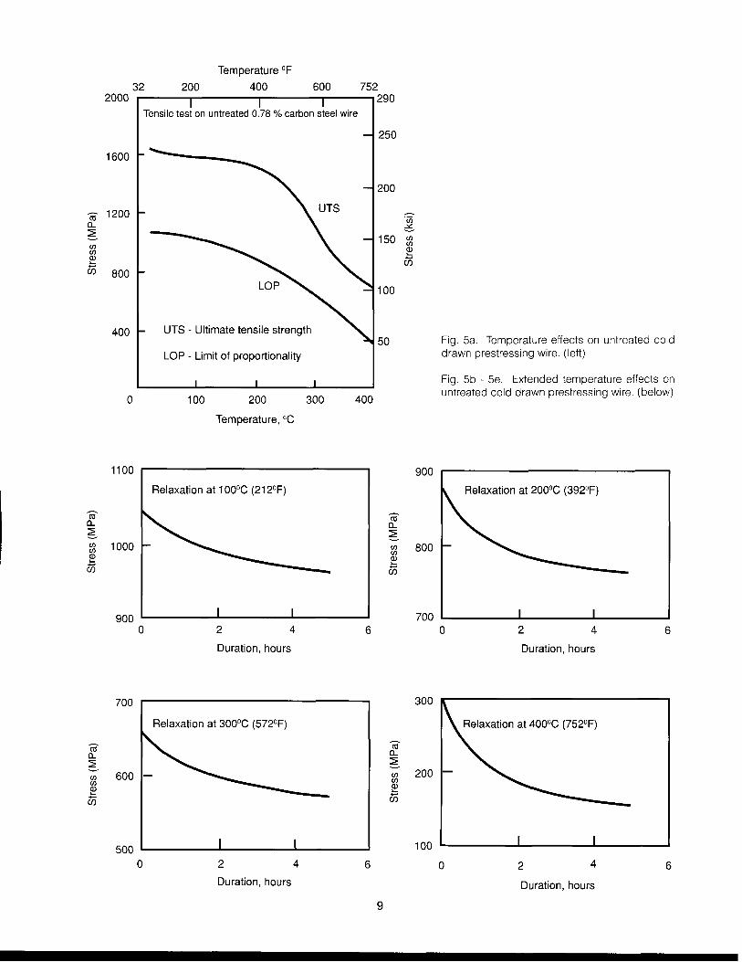
Spalling of prestressed concrete that exposes steel strand represents a serious problem. Exposed strand can often be an indication of loss of prestress, resulting in a reduced load carrying capacity of the member. As such, a structural evaluation must be made for determination of shoring requirements and other safety considerations. A visual inspection of the ends of the member should be made, if possible, to determine if any bond loss has occurred, accompanied by inward movement or slippage of the strand. Buckling of the strand is seldom encountered because it generally remains in tension, even though substantial prestress may have been relaxed or lost (see Figs. 5b-5e). Further explanation of this effect is given later in this report. If circumstances exist to warrant strong consideration for performing insitu repairs to prestressed members, a more detailed investigation is needed.
The observation of a pink discoloration to a given depth of concrete (see photo) indicates that minimum temperatures of 300°C (572°F) have occurred. This discoloration is accompanied by a significant loss of concrete strength within the discolored region. Some- times the discoloration can be seen without the need of extracting cores, such as in areas of spalled concrete. If this phenomenon has occurred, it can be used as a tool in determining the likelihood of damage
discoloration Also observe the partial change of aggregate color (upper right) from yellow gold to red
4
to non-prestressed reinforcing steel (bars). Where the depth of pink concrete is less than the cover thickness, the reinforcing steel is not likely to be seriously affected by temperature. If the pink discol- oration extends all the way to the reinforcement, further investigation of the steel's strength, and the concrete's strength beyond the depth of reinforcement is necessary. Concrete in the region of discoloration must be removed prior to making repairs.
Caution must be observed, however, in placing heavy reliance on this visual technique alone since the pink discoloration is not always apparent. Tovey attributes the pink discoloration phenomenon in heated concrete to the presence of ferrous salts in the cement paste, aggregate and/or sand. He also observes that concretes containing siliceous aggregates appear to be more susceptible to this reaction than those containing calcareous or igneous aggregates.@] With some fire-exposed concrete, the discoloration that occurs may be so faint that it is not discernible to the naked eye. In other instances, the pink discoloration doesn't occur. The latter supports the premise that it is not just the presence of elemental iron in concrete that leads to this reaction, but rather the stability of the iron- containing compounds that is important. Since the cause of the phenomenon is not fully understood, one should not conclude that the concrete is undamaged, based solely on the absence of the pink discoloration.
Shear failures in normal weight concrete beams exposed to fire are rare. This is supported by labora- tory tests and field investigations through the years. in a test program designed to investigate the shear and flexural behavior of concrete beams exposed to fire (Ref. 9), all of the test specimens exhibited shear crack- ing prior to the development of flexural cracks when subjected to the standard ASTM El 19('O)fire condition. Additionally, all of the beams failed by flexure rather than shear, even though some of the specimens showed considerable signs of shear distress. Thus, shear strength of beams at elevated temperatures does not appear to be a problem unless shear strength is inadequate at room temperature.
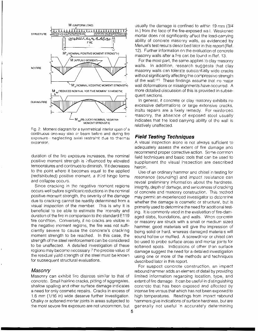
In continuous beams and slabs, it is not unusual to observe flexural cracking in the negative moment region (over the supports). This behavior can be explained by Fig. 2. Assuming that a sufficiently severe fire exists, a redistribution of moments takes place early in the fire exposure period. Redistributed moments are generally limited by the nominal negative moment strength near the supports and have the effect of significantly reducing the applied positive moment. In an ASTM El19 fire test, yielding of the negative moment reinforcement (Fig. 2c) typically occurs within the first 30 minutes. At some point from the beginning of the fire exposure to the time of yielding, the cracking moment strength in the negative moment regions is reached and cracks develop. As the
-1 -1 ..
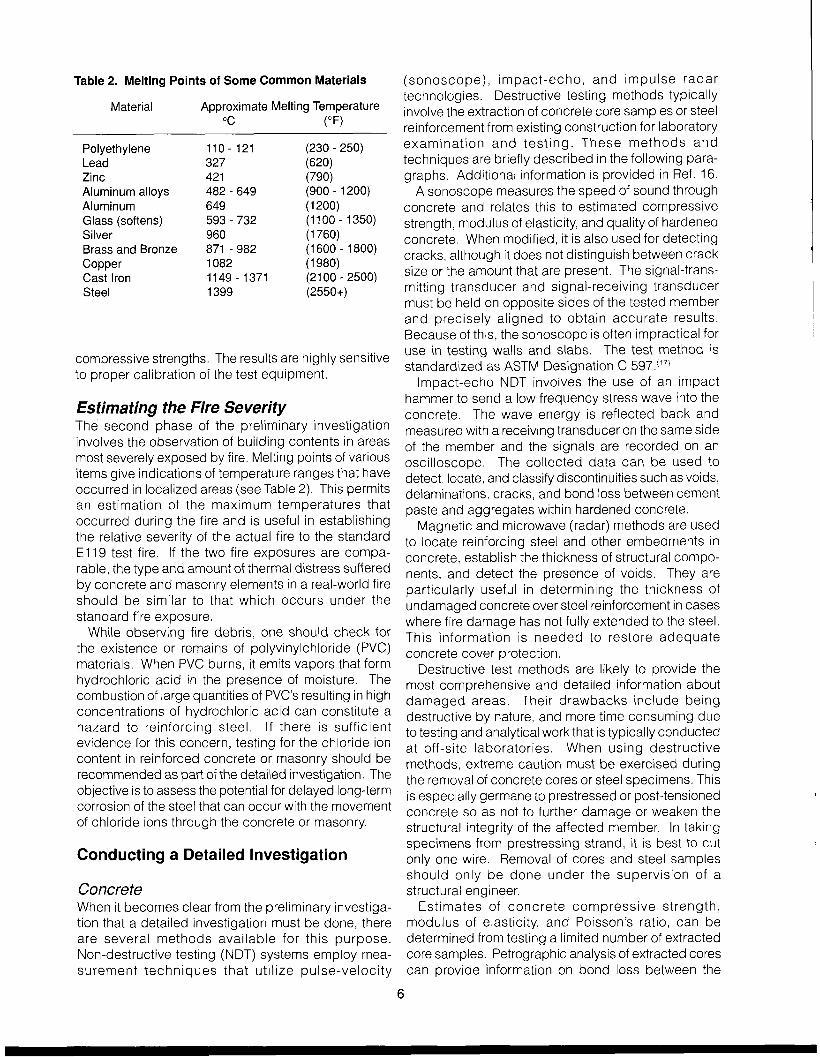
Table 2. Melting Points of Some Common Materials
Material Approximate Melting Temperature "C (OF)
Polyethylene Lead Zinc Aluminum alloys Aluminum Glass (softens) Silver Brass and Bronze Copper Cast Iron Steel
110 - 121 327 421
649
960
1082 1149 - 1371 1399
482 - 649
593 - 732
871 -982
(230 - 250) (620) (790) (900 - 1200) (1 200) (1100 - 1350)
(1 600 - 1800)
(21 00 - 2500)
(1 760)
(1 980)
(2550+)
compressive strengths. The results are highly sensitive to proper calibration of the test equipment.
Estimating the Fire Severity The second phase of the preliminary investigation involves the observation of building contents in areas most severely exposed by fire. Melting points of various items give indications of temperature ranges that have occurred in localized areas (see Table 2). This permits an estimation of the maximum temperatures that occurred during the fire and is useful in establishing the relative severity of the actual fire to the standard El19 test fire. If the two fire exposures are compa- rable, the type and amount of thermal distress suffered by concrete and masonry elements in a real-world fire should be similar to that which occurs under the standard fire exposure.
While observing fire debris, one should check for the existence or remains of polyvinylchloride (PVC) materials. When PVC burns, it emits vapors that form hydrochloric acid in the presence of moisture. The combustion of large quantities of PVC's resulting in high concentrations of hydrochloric acid can constitute a hazard to reinforcing steel. I f there is sufficient evidence for this concern, testing for the chloride ion content in reinforced concrete or masonry should be recommended as part of the detailed investigation. The objective is to assess the potential for delayed long-term corrosion of the steel that can occur with the movement of chloride ions through the concrete or masonry.
Conducting a Detailed Investigation
Concrete When it becomes clear from the preliminary investiga- tion that a detailed investigation must be done, there are several methods available for this purpose. Non-destructive testing (NDT) systems employ mea- surement techniques that utilize pulse-velocity
(sonoscope), impact-echo, and impulse radar technologies. Destructive testing methods typically involve the extraction of concrete core samples or steel reinforcement from existing construction for laboratory examination and testing. These methods and techniques are briefly described in the following para- graphs. Additional information is provided in Ref. 16.
A sonoscope measures the speed of sound through concrete and relates this to estimated compressive strength, modulus of elasticity, and quality of hardened concrete. When modified, it is also used for detecting cracks, although it does not distinguish between crack size or the amount that are present. The signal-trans- mitting transducer and signal-receiving transducer must be held on opposite sides of the tested member and precisely aligned to obtain accurate results. Because of this, the sonoscope is often impractical for use in testing walls and slabs. The test method is standardized as ASTM Designation C 597.(17)
Impact-echo NDT involves the use of an impact hammer to send a low frequency stress wave into the concrete. The wave energy is reflected back and measured with a receiving transducer on the same side of the member and the signals are recorded on an oscilloscope. The collected data can be used to detect, locate, and classify discontinuities such as voids, delaminations, cracks, and bond loss between cement paste and aggregates within hardened concrete.
Magnetic and microwave (radar) methods are used to locate reinforcing steel and other embedments in concrete, establish the thickness of structural compo- nents, and detect the presence of voids. They are particularly useful in determining the thickness of undamaged concrete over steel reinforcement in cases where fire damage has not fully extended to the steel. This information is needed to restore adequate concrete cover protection.
Destructive test methods are likely to provide the most comprehensive and detailed information about damaged areas. Their drawbacks include being destructive by nature, and more time consuming due to testing and analytical work that is typically conducted at off-site laboratories. When using destructive methods, extreme caution must be exercised during the removal of concrete cores or steel specimens. This is especially germane to prestressed or post-tensioned concrete so as not to further damage or weaken the structural integrity of the affected member. In taking specimens from prestressing strand, it is best to cut only one wire. Removal of cores and steel samples should only be done under the supervision of a structural engineer.
Estimates of concrete compressive strength, modulus of elasticity, and Poisson's ratio, can be determined from testing a limited number of extracted core samples. Petrographic analysis of extracted cores can provide information on bond loss between the
6
w (UNIFORM LOAD)
M+,(NOMINAL POSITIVE MOMENT STRENGTH) - A
NO FIRE
w M-"(NOMINAL NEGATIVE MOMENT STRENGTH)
M+nB(REDUCED NOMINAL POSITIVE MOMENT STRENGTH) ,
DURING FIRE
M-,,(REDUCED NOMINAL NEGATIVE MOMENT STRENGTH)
Fig. 2. Moment diagram for a symmetrical interior span of a
usually the damage is confined to within 19 mm (3/4 in.) from the face of the fire-exposed wall. Weakened mortar does not significantly affect the load-carrying ability of concrete masonry walls, as evidenced by Menzel's test results described later in this report (Ref. 12). Further information on the evaluation of concrete masonry walls after a fire can be found in Ref. 13.
For the most part, the same applies to clay masonry walls. In addition, research suggests that clay masonry walls can tolerate substantially wide cracks without significantly affecting the compressive strength of the These findings assume that no major wall deformations or misalignments have occurred. A more detailed discussion of this is provided in subse- quent sections.
In general, if concrete or clay masonry exhibits no excessive deformations or large extensive cracks, insitu repairs are a likely remedy. For reinforced masonry, the absence of exposed steel usually indicates that the load-carrying ability of the wall is relatively unaffected.
c6ntinuous one-w& slab or beam before and during fire exposure-neglecting axial restraint due to thermal exoansion.
Field Testing Techniques A visual inspection alone is not always sufficient to adequately assess the extent of fire damage and recommend proper corrective action. Some common field techniques and basic tools that can be used to supplement the visual inspection are described herein,
Use of an ordinary hammer and chisel in testing for resonance (sounding) and impact resistance can reveal preliminary information about the hardness, integrity, depth of damage, and seriousness of cracking of concrete and masonry construction, This method may permit an experienced investigator to determine whether the damage is cosmetic or structural, but is
duration Of the fire exposure increases, the nOminal positive moment strength is influenced by elevated temperatures and continues to diminish. If it decreases to the point where it becomes equal to the applied (redistributed) positive moment, a third hinge forms and collapse occurs.
Since cracking in the negative nxm~ent regions OCCUrS Well before Significant reductions in the nOminal positive moment strength, the severity Of the damage due to cracking cannot be readily determined from a Visual inspection Of the member. This is why it is beneficial to be able to estimate the intensity and duration Of the fire in comparison to the standard E l 19 fire condition. Conversely, if no cracks are visible in the negative mOtTIent regions, the fire Was not suffi- ciently severe to cause the concrete's cracking moment strength to be reached. In this case, the
primarily used to determine the need for additional test- ing, It is commonly used in the evaluation of fire-dam- aged slabs, foundations, and walls, When concrete or masonry are struck with a small or medium sized hammer, good materials will give the impression of being solid or hard, whereas damaged materials will sound hollow or muffled. A screwdriver or chisel can
strength of the steel reinforcement can be considered be used to probe surface areas and mortar joints for to be unaffected. A detailed investigation Of these softened spots, Indications of other than surface regions may become necessary if the Precise value of damage suggest the need for a detailed investigation the residual yield strength Of the Steel must be known using one or more of the methods and techniques for subsequent structural evaluations. described later in this report.
For suspect concrete construction, an impact Masonry rebound hammer adds an element of detail by providing Masonry can exhibit fire distress similar to that of limited information regarding location, type, and concrete. Small hairline cracks, pitting of aggregates, extent of fire damage. It can be useful in distinguishing shallow spalling and other surface damage indicates concrete that has been exposed and affected by a need for only cosmetic repairs. Cracks in excess of intense fire versus that which has not been exposed to 1.6 mm (1/16 in) wide deserve further investigation. high temperatures. Readings from impact rebound Chalky or softened mortar joints in areas subjected to hammers give indications of surface hardness, but are the most severe fire exposure are not uncommon, but generally not useful in accurately determining
5
Temperature, O F
32 400 800 1200 1472 140
120
100
G' g 80 co
9 0 N
m
al
0
c
9 =-. 60
8
._ -
40
20
Hot
0 200 400 600 800 Temperature, "C
Hot rolled mild steel (rebars) Hot rolled high yield (bars)
Cold worked high yield (wire mesh)
------- - - - - -
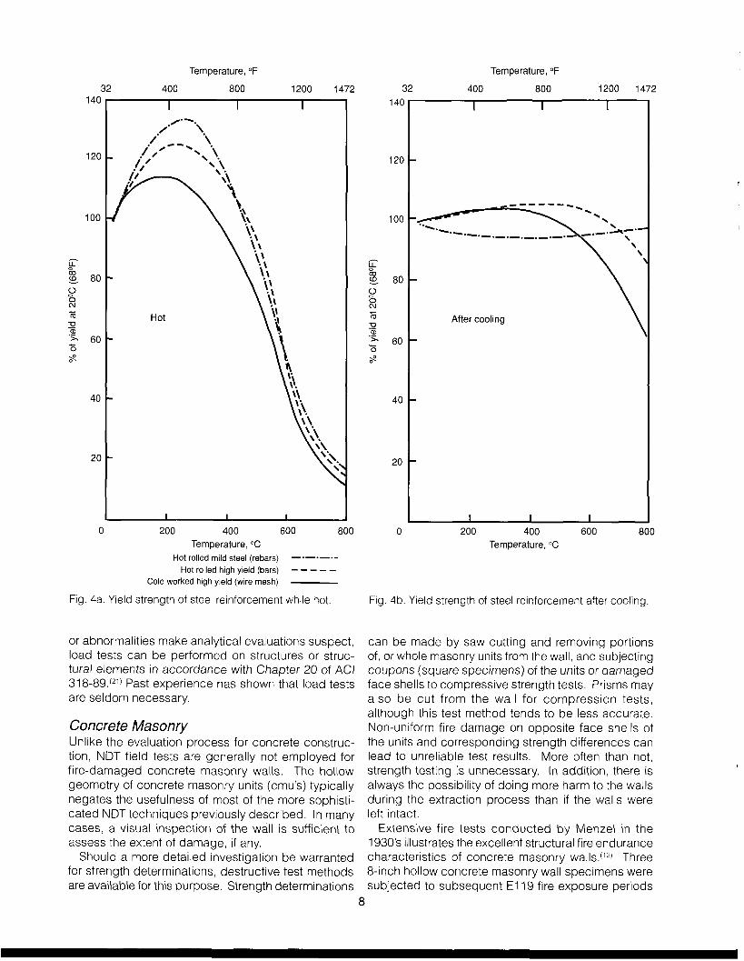
Fig. 4a. Yield strength of steel reinforcement while hot.
or abnormalities make analytical evaluations suspect, load tests can be performed on structures or struc- tural elements in accordance with Chapter 20 of ACI 31 8-89.(21) Past experience has shown that load tests are seldom necessary.
Concrete Masonry Unlike the evaluation process for concrete construc- tion, NDT field tests are generally not employed for fire-damaged concrete masonry walls. The hollow geometry of concrete masonry units (cmu's) typically negates the usefulness of most of the more sophisti- cated NDT techniques previously described. In many cases, a visual inspection of the wall is sufficient to assess the extent of damage, if any.
Should a more detailed investigation be warranted for strength determinations, destructive test methods are available for this purpose. Strength determinations
140
120
100
G' g 80 9 co
0 N
m
0,
0
c
n ," 60
s
._
40
20
0
Temperature, O F
32 400 800 1200 1472
I I I
After cooling
200 400 600 800 Temperature, OC
Fig. 4b. Yield strength of steel reinforcement after cooling.
can be made by saw cutting and removing portions of, or whole masonry units from the wall, and subjecting coupons (square specimens) of the units or damaged face shells to compressive strength tests. Prisms may also be cut from the wall for compression tests, although this test method tends to be less accurate. Non-uniform fire damage on opposite face shells of the units and corresponding strength differences can lead to unreliable test results. More often than not, strength testing is unnecessary. In addition, there is always the possibility of doing more harm to the walls during the extraction process than if the walls were left intact.
Extensive fire tests conducted by Menzel in the 1930's illustrates the excellent structural fire endurance characteristics of concrete masonry walls.(iz) Three 8-inch hollow concrete masonry wall specimens were subjected to subsequent E l 19 fire exposure periods
8
cement matrix and reinforcing steel, crack orientation and their relationship to the aggregate, microcracking, extent of concrete dehydration, chemical compositional changes of cementitious materials and aggregates, and temperature distribution within a given concrete depth.
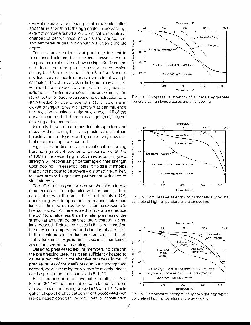
Temperature gradient is of particular interest in fire-exposed columns, because once known, strength- temperature relationships shown in Figs. 3a-3c can be used to estimate the post-fire residual compressive strength of the concrete. Using the "unstressed residual" curves leads to conservative residual strength estimates. The other curves in the figures may be used with sufficient expertise and sound engineering judgment. Pre-fire load conditions of columns, the redistribution of loads to surrounding construction, and stress reduction due to strength loss of columns at elevated temperatures are factors that can influence the decision in using an alternate curve. All of the curves assume that there is no significant internal cracking of the concrete.
Similarly, temperature-dependent strength loss and recovery of reinforcing bars and prestressing steel can be estimated from Figs. 4 and 5, respectively, provided that no quenching has occurred.
Figs. 4a-4b indicate that conventional reinforcing bars having not yet reached a temperature of 592°C (1 IOOOF), representing a 50% reduction in yield strength, will recover a high percentage of their strength upon cooling. In essence, bars in flexural members that do not appear to be severely distorted are unlikely to have suffered significant permanent reduction of yield strength.
The effect of temperature on prestressing steel is more complex. In conjunction with the strength loss associated with the limit of proportionality (LOP) decreasing with temperature, permanent relaxation losses in the steel can occur well after the exposure to fire has ended. As the elevated temperatures reduce the LOP to a value less than the initial prestress of the strand (at ambient conditions), the prestress is simi- larly reduced. Relaxation losses in the steel based on the maximum temperature and duration of exposure, further contribute to a reduction in prestress. This ef- fect is illustrated in Figs. 5a-5e. These relaxation losses are not recovered upon cooling.
Deflected prestressed flexural members indicate that the prestressing steel has been sufficiently heated to cause a reduction in the effective prestress force. If precise values of the steel's residual yield strength are needed, various metallographic tests for microhardness can be performed as described in Ref. 20.
For guidance on other evaluation methods, ACI Report 364.1 W5) contains tables correlating appropri- ate evaluation and testing procedures with the investi- gation of specific physical conditions associated with fire-damaged concrete. Where unusual construction
Temperature, "F
32 400 aoo 1200 1600 100 - _ \ \ J Stressed to 0.4 fc
I \ I I I I
' ' . . 1 ' \
Unstressed \ A\
'. Y ' -- L Unstressed Residual -' ? m
Avg. Initial f c = 26.91 MPa (3900 psi)
Q
E 20
0 ' I I I I 1 0 200 400 600 aoo
Temperature, OC
Fig. 3a. Compressive strength of siliceous aggregate concrete at high temperatures and after cooling.
Temperature, OF
32 400 800 1200 1600 ._ 100 I I I
-.. -.. Avg. Initial f c = 26.91 MPa (3900 psi)
Carbonate Aggregate Concrete 20
1 0 200 400 600 aoo
Temperature, "C
Fig. 3b. Compressive strength of carbonate aggregate concrete at high temperature and after cooling.
Temperature, "F
32 400 800 1200 1600
Stressed to
unstressed .\ 80 \ (unsanded)---;)'--,
Unstressec
60 Residualf '' .. (sanded)
Unstressed ' -_ . , O t
Avg. Initial f c of "Unsanded" Concrete = 17.9 MPa (2600 psi)
Avg. Initial f c of "Sanded Concrete = 26.9MPa (3900 psi) c Lightweight Aggregate Concrete
0 I I I I
0 200 400 600 aoo Temperature, OC
Fig 3c. Compressive strength of lightweight aggregate concrete at high temperature and after cooling.
7
Temperature OF 32 200 400 600 752
2000
1600
Q 1200
5 a
v) v)
? tj 800
400
0
1100
h m a E g 1000 E 5
900
I I I Tensile test on untreated 0.78 % carbon steel wire
UTS - Ultimate tensile strength
LOP - Limit of proportionality I 100 200 300 400
Temperature, "C
Relaxation at 1 OOOC (212°F)
I I _ _ _
0 2 4 6
Duration. hours
700 I I
500 I I I I 0 2 4 6
Duration, hours
Ld"
250
200
h v)
Y 150 2
? z 100
50
h m a E ? tj
v) v)
h m a z ? tj
v) 0
Fig. 5a. Temperature effects on untreated cold drawn prestressing wire. (left)
Fig. 5b - 5e. Extended temperature effects on untreated cold drawn prestressing wire. (below)
900 I
0 2 4 6
Duration, hours
Relaxation at 4OOOC (752OF)
100 I 0 2 4 6
Duration, hours
9

of 2 and 1/2 hours after being initially tested for periods of 2 and 1/2,3, and 3 and 1/2 hours, respectively. Upon conducting strength tests, results showed no appre- ciable differences in wall-to-unit strength ratios than were experienced from conventional single fire exposure test procedures. The results suggest that concrete masonry walls can withstand one severe fire without replacement, and still be able to perform structurally in the event of a second severe fire. Menzel's fire test program of 21 5 concrete masonry walls additionally showed that mortar joints generally softened to a depth of about 12-19 mm (one-half to three-fourths inch) from the exposed face when subjected to ASTM E l 19 fires for varying periods of up to 9 hours. The evidence suggests that weakened mortar has little effect on the axial load carrying ability of concrete masonry walls.
Clay Masonry For many of the same reasons expressed regarding concrete masonry, post-fire inspection procedures for clay masonry walls are typically limited to a visual investigation. As with concrete masonry, signs of deflection, cracking, deformation, and surface defects should be observed and documented. Some behavioral information on clay masonry walls exposed to fire is provided below.
The high fire resistance of fired clay brickwork is well known, but its ability to retain strength on cooling compared with other materials is not sufficiently appreciated. Clay masonry units show little strength loss when heated to temperatures of up to 1000°C (1832"F), while mortars have virtually no strength at these temperatures and begin to lose substantial strength at temperatures above 300-400°C (572- 752°F). However, mortar damage is usually confined to a shallow depth of approximately 12-19 mm (one-half to three-fourths inch) from the surface.
While clay masonry units can have compressive strengths of up to about 138 MPa (20,021 psi), the allowable height for loadbearing unreinforced masonry walls is limited by slenderness restrictions (height-to- thickness ratios). The greater the unsupported wall height for a given thickness (increasing slenderness ratio), the more susceptible it is to buckling." Expo- sure to heat from interior fire exposure accentuates this behavior, as differential expansion between hot and cool surfaces causes the wall to bow towards the fire. If the deflection exceeds a critical amount, the wall becomes unstable and experiences sudden collapse. Research suggests that this critical point occurs as the mid-height deflection of the wall reaches about 80%
of the wall thickness.(2z) The direction in which the wall collapses will depend on the type and integrity of the lateral support system.
Test results from over 200 full-scale fire tests and aux- iliary tests in Australia comparable to ASTM E 1 19 fire testing support the conclusion that concentrically loaded masonry walls (unreinforced and reinforced) do not suffer sufficient strength loss at elevated temperatures for walls to fail in compression.(zz) When fire-exposed clay masonry walls fail, buckling is more likely to control the mode of failure. This is largely due to the bond strength between the mortar and brick being substantially lower than the reduced compres- sive strength of the wall. Adding reinforcement to clay masonry walls virtually eliminates this buckling potential.
Cracked loadbearing walls, within limits, still have substantial load carrying capabilities. Results of structural tests conducted under non-fire conditions at the Building Research Station in England have shown that 229-mm (9-inch) brick walls with a stepped or slanted crack up to 25 mm (1 inch) wide can still carry a minimum of 70% of its vertical load capacity provided that the damage is not accompanied by considerable transverse displacement. If walls are out of plumb by not more than 25 mm (1 in), or bulge no more than 12 mm (1/2 in) in a normal story heightb no repairs are usually necessary on structural grounds alone.(I4) Because fire (up to about 1000°C (1852°F)) has very little effect on the compressive strength of clay masonry walls, it is reasonable to assume that cracks of the aforementioned width will impact the heat-reduced load carrying capabilities of masonry walls to a similar extent. Cracks of the magnitude indicated above are significantly larger than those that would be expected due to fire exposure.
Buckling of clay masonry walls due to exterior fire exposure is extremely rare. It is reasonable to attribute this in part to the fastening system that gives the wall stability as it bows outward toward the fire. In the case of brick veneer walls, the wall is kept from buckling due to restraint provided by wall ties and framing elements. If the fire does not enter the building through openings, thereby leaving the integrity of the connec- tions unaffected, brick masonry is capable of withstand- ing even severe fire exposure for prolonged periods of time. Some brick veneer walls (90 mm and 110 mm (3.5 in. and 4.3 in.) masonry wythes) in the Australian test program were able to withstand the fire test for over two hours.(zz)
a For purposes of this section, the term "buckling" is used to describe the phenomenon of excessive bowing resulting in collapse due to tensile or shear bond failure at the brick-mortar interface.
bAlthough most of the author's consulting work is done on commer- cial/industrial projects, normal story height should be assumed to range between 2.4-3.6 m (8-1 2 ft). A conservative approach should be taken where marginal conditions are present.
10

The Repair Process Concrete Repair Options Versus Demolition and Rebuilding As mentioned previously, concrete structures are more likely to be repairable after a fire than wood or steel- framed structures. In assessing the repair alternatives, completion of the detailed investigation largely deter- mines how much work is required. Depending on the degree of damage, some concrete members may need no repair due to overdesign, some may only need cosmetic repairs, and others may have to be strength- ened or removed and replaced.
Repair work should be supervised by a structural engineer for numerous reasons. For example, unsafe load transfers that may occur during shoring opera- tions or during the removal and replacement of structural members must be accounted for and guarded against. Loads that are to be supported by new concrete must be temporarily supported by other means during the placement and curing periods. Design standards and load requirements may have also changed since the building was erected, requir- ing modified sections to comply with current building codes. In addition, structural evaluations may become necessary at various stages of the project, should any deviations in the repair process occur.
Most damaged structures can be repaired using the same concrete Dlacement techniques that are used
Removal and replacement - Favorable characteristics of a removal and replace- ment process can include:
it is likely to be less expensive than insitu repairs for severely damaged members overcomes space or dimension limitation problems sometimes experienced with in-place repair tech- niques, e.g., shotcreting when space between steel is less than 64 mm (2.5 in.) it is more conducive to precast concrete construc- tion due to relative ease of removal, and, it is less dependent on the quality of the original construction and antiquated design features.
Drawbacks can include: greater debris removal costs accessibility problems may necessitate the removal and replacement of sound walls and/or roofing more shoring is required to carry the loads for- merly carried by removed members increased structural analytical work and supervision is required to assure that excessive loads are not transferred to other members during various stages of the removal and replacement process temporary walls and coverings may need to be erected, and, undamaged members and supports may become damaged in the process of removing damaged sections.
for new construction. Original building design and space restrictions, however, can often have a signifi-
repair method. Installation considerations and
respect to repair alternatives are described below.
Demolition andrebuilding -This is not an economically feasible alternative except in extremely rare cases,
demolition is usually a very difficult, time consuming,
to its exceptional durability and monolithic construction.
cant influence On the selection Of an appropriate Particularly with cast-in-place concrete construction,
economic factors that may not be readily apparent with expensive, and disruptive process, This is largely due
lnsitu restoration - Favorable characteristics of insitu restoration can include:
it can be done in a relatively short period of time occupancy of undamaged portions of the building
business interruption losses are minimized no large specialized equipment is necessary minimal or no shoring is required, and, debris removal and disruption from construction traffic
can continue
are minimized.
Drawbacks can include: it can be more costly than removal and replacement for severely damaged members it is less feasible for extensive damage to beams and slabs, and, repair work can become costly if the quality and design of original construction greatly differs from current code requirements.
Effecting Repairs For concrete, the most common repair approach is to patch the existing member with concrete and install reinforcing steel where necessary to restore the load carrying capacity. Loose and damaged concrete should be chiseled away, being careful not to disturb the bond between the steel and the undamaged con- crete. Sandblasting should be done to clean steel and concrete surfaces that are to receive fresh concrete. Smooth concrete surfaces should also be sufficiently roughened by bushhammering or sandblasting prior to placing fresh concrete. Repair techniques for fire- damaged concrete are basically the same as those used for repairing any other types of distressed concrete, i.e., forming, shotcreting, etc. One possible exception involves the use of epoxies and this is discussed later. Detailed repair procedures are outside the scope of this report. Ref. 23, however, provides an excellent source of information on repair techniques.
If structural members are required to possess fire
11
resistance by the governing building codes, epoxy resins should not be used for the repair of large cracks or spalled areas that would result in inadequate concrete cover protection to reinforcement.(8) Epoxy resins have low melting points that make them susceptible to run off in the event of a fire. Unless appropriate test data is available indicating that a specific product can demonstrate this type of thermal resistance, epoxy resins should not be used for this application. An exception would be for patching of cracks in areas of decreased fire exposure such as negative moment regions of flexural members.
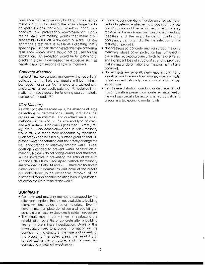
Concrete Masonry If a fire-distressed concrete masonry wall is free of large deflections, it is likely that repairs will be minimal. Damaged mortar can be removed and tuckpointed, and cracks can be readily patched. For detailed infor- mation on crack repair, the following source material can be referenced .(14,24)
Clay Masonry As with concrete masonry walls, the absence of large deflections or deformations usually indicates that repairs will be minimal. For cracked walls, repair methods will depend on the size and type of crack and wall surface. Fine cracks (less than 1.6 mm (1/16 in)) are not very conspicuous and in brick masonry would often be made more noticeable by repointing. Such cracks can be filled by surface grouting that will prevent water penetration and not greatly change the wall appearance of relatively smooth walls. Clear coatings intended to prevent water penetration of masonry typically do not bridge cracks and, therefore, will be ineffective in preventing the entry of Additional details on crack repair methods for masonry are provided in Refs. 14 and 26. If there are no severe deflections or deformations and none of the cracks are considered to be excessive, removal of the distressed mortar and tuckpointing is usually sufficient for complete restoration of the
SUMMARY Concrete and masonry members damaged by fire offer repair options that are not available to building elements constructed of other materials. Even in severe fires, complete demolition and rebuilding of concrete and masonry structures is seldom necessary. The single most important item in evaluating the rehabilitation potential of concrete after a building fire is the preliminary investigation. Goals of this investigation are to provide information on the condition of the structure, the type and severity of the problems in affected areas, the feasibility of rehabilitating the structure, and the need for conducting a detailed investigation.
Economic considerations must be weighed with other factors to determine whether insitu repairs of concrete construction should be performed, or removal a n d replacement is more feasible. Existing architectural features and the importance of continuing occupancy can often dictate the selection of the restoration process. Nonprestressed concrete and reinforced masonry members whose cover protection has remained in place after fire exposure are unlikely to have suffered any significant loss of structural strength, provided that no major deformations or misalignments have occurred. No field tests are generally performed in conducting investigations to assess fire-damaged masonry walls. Post-fire investigations typically consist only of visual inspections. If no severe distortion, cracking or displacement of masonry walls is present, complete reinstatement of the wall can usually be accomplished by patching cracks and tuckpointing mortar joints.
12
REFERENCES
1.
2.
3.
4.
5.
6.
7.
8.
9.
10.
11.
Fitzgerald, Robert W., “Structural Integrity During Fire,” Fire Protection Handbook, 16th edition, National Fire Protection Association, Quincy, MA,
Structural Fire Protection: Manual of Practice, T.T. Lie, editor, prepared by the ASCE Committee on Fire Protection - Structural Division, American Society of Civil Engineers, New York, NY, 1992, P. 70. Reinforced Concrete Fire Resistance, First edition, prepared by the CRSl Committee on Fire Ratings, Concrete Reinforcing Steel Institute, Chicago, IL,
Gustaferro, Armand H., “Experiences From Evaluating Fire-Damaged Concrete Structures,” Fire Damaged Structures, ACI SP 80-10, American Concrete Institute, Detroit, MI, P. 276. ACI Committee 364, “Guide for Evaluation of Con c ret e St r u c t u res Prior to Re h a b i I it at i on, ” Report 364.1R3, published in ACI MateriaIs Journal, Sept.-Oct. 1993, American Concrete Institute, Detroit, MI, 1993. I’ C o n c re t e S t r u c t u re s Aft e r F i re , ” Concrete Construction, March 1972, Vol. 17, Number 3, Concrete Construction Publications, Inc., Addison, IL, 1972, P. 101. Krampf, L. and Haksever, A,, “Possibilities of Assessing the Temperatures Reached by Concrete Building Elements During a Fire,”Evaluation and Repair of Fire Damage to Concrete, T.Z. Harmathy, editor, ACI SP 92, American Concrete Institute, Detroit, MI, 1986, P. 127. Tovey, A.K., “Assessment and Repair of Fire- Damaged Concrete Structures-an Update,” Evaluation a n d Repair of Fire Damage to Concrete, T.Z. Harmathy, editor, ACI SP 92, American Concrete Institute, Detroit, MI, 1986, P. 50. Lin, T.D., Ellingwood, Bruce, and Piet, Olivier, Flexural and Shear Be ha vior of Rein forced Concrete Beams During Fire Tests, PCA Research and Development Bulletin RDOSlT, Portland Cement Association, Skokie, IL, 1987. ASTM Designation E 1 19-88, “Standard Methods of Fire Tests of Building Construction and
Materials,” Section 4, Vol. 4.07, American Society for Testing and Materials, Philadelphia, PA, 1 993. Reinforced Concrete Fire Resistance, First edition, prepared by the CRSl Committee on Fire
1986, P. 7-103.
1980, P. 5-1.
12.
13.
14.
15.
16.
17.
18.
19.
20.
21.
22.
23.
Ratings, Concrete Reinforcing Steel Institute, Chicago, IL, 1980, P. 8-4. Menzel, Carl A,, Tests of the Fire Resistance and Strength of Walls of Concrete Masonry Units, Portland Cement Association, Chicago, IL, 1934. Evaluation of Concrete Masonry Walls After Being Subjected to Fire, NCMA TEK 7-5 (formerly TEK 11 7), National Concrete Masonry Association, Herndon, Virginia, 1980. Grimm, C.T., “Masonry Cracks: A Review of the Literature,”Masonry: Materials, Design, Construc- tion, and Maintenance, ASTM STP 992, Harry A. Harris, editor, American Society for Testing and Materials, Philadelphia, PA, 1988, P. 257-280. Gustaferro, Armand H., and Martin, Leslie D., Design for Fire Resistance of Precast Prestressed Concrete, Second edition, PCI MNL-124, Prestressed Concrete institute, Chicago, IL, 1989, P. 65. Muenow, Richard A,, and Abrams, Melvin S., “ N on destructive Testing Methods for Eva1 uat i n g Damage and Repair of Concrete Exposed to Fire,” Evaluation and Repair of Fire Damage to Concrete, T.Z. Harmathy, editor, ACI SP 92, American Concrete Institute, Detroit, MI, P. 63-86. ASTM Designation C 597-83 (Reapproved 1991), “Standard Test Method for Pulse Velocity Through Concrete, Section 4, Vol. 4.02, American Society for Testing and Materials, Philadelphia, PA, 1993. Abrams, M.S., Behavior of Inorganic Materials in Fire, PCA Research and Development Bulletin RD067.01 M, Portland Cement Association, Skokie, IL, 1980, P. 7. “Assessment and Reinstatement of Fire Damaged Concrete Structures,” Concrete for Fire Resistant Construction - Cembureau report published by the Cement and Concrete Association, Wexham Springs, Slough, 1979, P. 35-36. Abrams, M.S., and Erlin, B., Estimating Post-Fire Strength a n d Exposure Temperature of Prestressing Steel by a Metallographic Method, PCA Research Dept. Bulletin 219, Portland Cement Association, Skokie, IL, 1967. ACI Committee 31 8, “Building Code Requirements for Reinforced Concrete, (ACI 31 8-89) (Revised 1992),” American Concrete Institute, Detroit, MI, 1992. Gnanakrishnan, N. and Lawther, R., “Performance of Masonry Walls Exposed to Fire,” Proceedings, Fifth North American Masonry Conference, Vol. I l l , University of Illinois at Champaign/Urbana, June 3-6, 1990, P. 901-914. “Reinstating Fire-Damaged Structures,” Concrete
13

Construction, May 1972, Vol. 17, Number 5, Concrete Construction Publications, Inc., Addison, IL, 1972.
24. Maintenance of Concrete Masonry Walls, NCMA TEK 8-1 (formerly TEK 44), National Concrete Masonry Association, Herndon, Virginia, 1972.
25. Colorless Coatings for Brick Masonry, BIA Technical Notes on Brick Construction 7E, Brick Institute of America, Reston, Virginia, Reissued February 1987.
26. Moisture Resistance of Brick Masonry- Maintenance, BIA Technical Notes on Brick Construction 7F, Brick Institute of America, Reston, Virginia, Reissued February 1987.
27. Bricks - Their Properties and Use, The Brick Development Association, The Construction Press Ltd., Lancaster, England, 1974, P. 204.
14

Member organizations of the NATIONAL CODES AND STANDARDS COUNCIL:
AC I ASCC BIA ESCSI NAA NCMA NRMCA NSA PCA PC I TCA WRI
American Concrete Institute American Society for Concrete Construction Brick Institute of America Expanded Shale Clay & Slate Institute National Aggregates Association National Concrete Masonry Association National Ready Mixed Concrete Association National Stone Association Portland Cement Association Precast/Prestressed Concrete Institute Tilt-up Concrete Association Wire Reinforcement Institute
This publication is intended for the use of professional personnel competent to evaluate the significance and limitations of its contents and who will accept responsibility for the application of the material it contains. The National Codes and Standards Council of the Concrete and Masonry Industries disclaims any and all responsibility for the application of the stated principles or for the accuracy of the sources other than work performed or information developed by the Council.
National Codes and Standards Council o€ the Concrete and Masonry Industries 5420 Old Orchard Road, Skokie, Illinois 60077-1083
Printed in U.S.A. 33322.01 B