Embed Size (px)
Citation preview
Assessment of earthquake-related geohazards
and seismic design of onshore and offshore pipelines
by
Prodromos PSARROPOULOS
Andreas ANTONIOU
31 March 2016
Geneva, Switzerland
IPLOCA
Novel Construction Spring Plenary Session
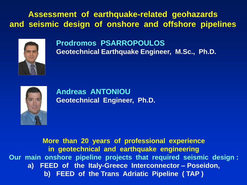
Prodromos PSARROPOULOS Geotechnical Earthquake Engineer, M.Sc., Ph.D.
Andreas ANTONIOU Geotechnical Engineer, Ph.D.
Assessment of earthquake-related geohazards
and seismic design of onshore and offshore pipelines
More than 20 years of professional experience
in geotechnical and earthquake engineering
Our main onshore pipeline projects that required seismic design :
a) FEED of the Italy-Greece Interconnector – Poseidon,
b) FEED of the Trans Adriatic Pipeline ( TAP )

Presentation Contents
1. Introduction
2. Quantitative assessment and treatment of geohazards
• Strong ground motion
• Active-fault rupture
• Soil liquefaction
• Slope instability
3. Proposals and general conclusions

Presentation Contents
1. Introduction
2. Quantitative assessment and treatment of geohazards
• Strong ground motion
• Active-fault rupture
• Soil liquefaction
• Slope instability
3. Proposals and general conclusions
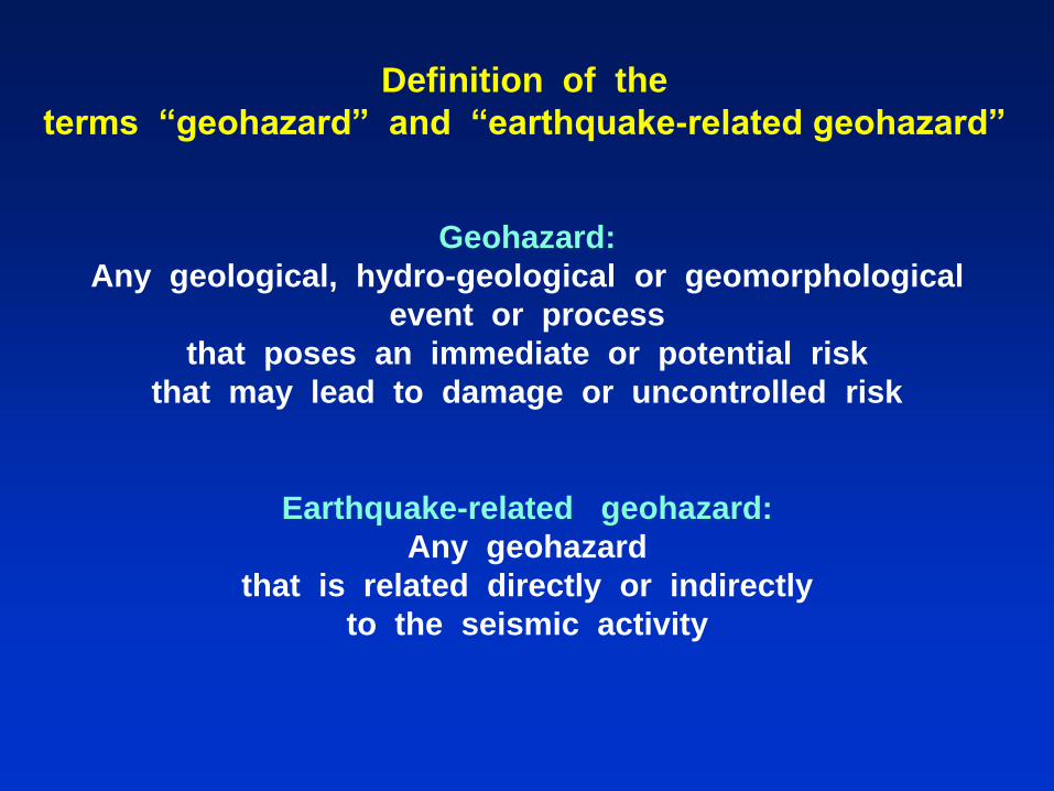
Geohazard:
Any geological, hydro-geological or geomorphological
event or process
that poses an immediate or potential risk
that may lead to damage or uncontrolled risk
Earthquake-related geohazard:
Any geohazard
that is related directly or indirectly
to the seismic activity
Definition of the
terms “geohazard” and “earthquake-related geohazard”

To assess global oil and gas deposits,
major onshore ( and/or offshore ) pipelines
will traverse remote regions with extreme terrains
( and/or seabeds ).
Many pipeline projects, constructed or planned,
are in tropical jungles, mountains and deserts, in permafrost
and wetlands ( or deep waters ).
Each of these natural environments is associated
with a range of geohazards,
which may include landslides, soil erosion, karst,
river migration, and seismic or volcanic activity.
At the same time, society demands
increasing availability and reliability of supply,
together with improved environmental standards,
all making for substantial challenges.
Motivation of the presentation (1/3)

According to the Road to Success ( RtS ) of IPLOCA:
a) Terrain, soil types, and geohazards
traversed by an onshore pipeline are key factors to consider
in the design, construction, operation and maintenance
of a pipeline project.
b) Earthquakes and fault lines are included
in the list of geohazard types for onshore pipelines.
Nevertheless, since in many areas
characterized by moderate or high seismicity
the avoidance of a “problematic area” is not feasible,
the quantitative assessment and effective treatment
of an earthquake-related geohazard
is a demanding and challenging issue
directly related to the pipeline integrity.
Motivation of the presentation (2/3)
On the other hand,
the simplistic provisions of the seismic standards / norms
( e.g. ISO, PRCI, EN )
are rather incapable to cover sufficiently all the issues
of the seismic design of onshore pipelines.
Important note:
For the time being,
there exists no standard / norm worldwide
that covers the seismic design of offshore pipelines !
Motivation of the presentation (3/3)
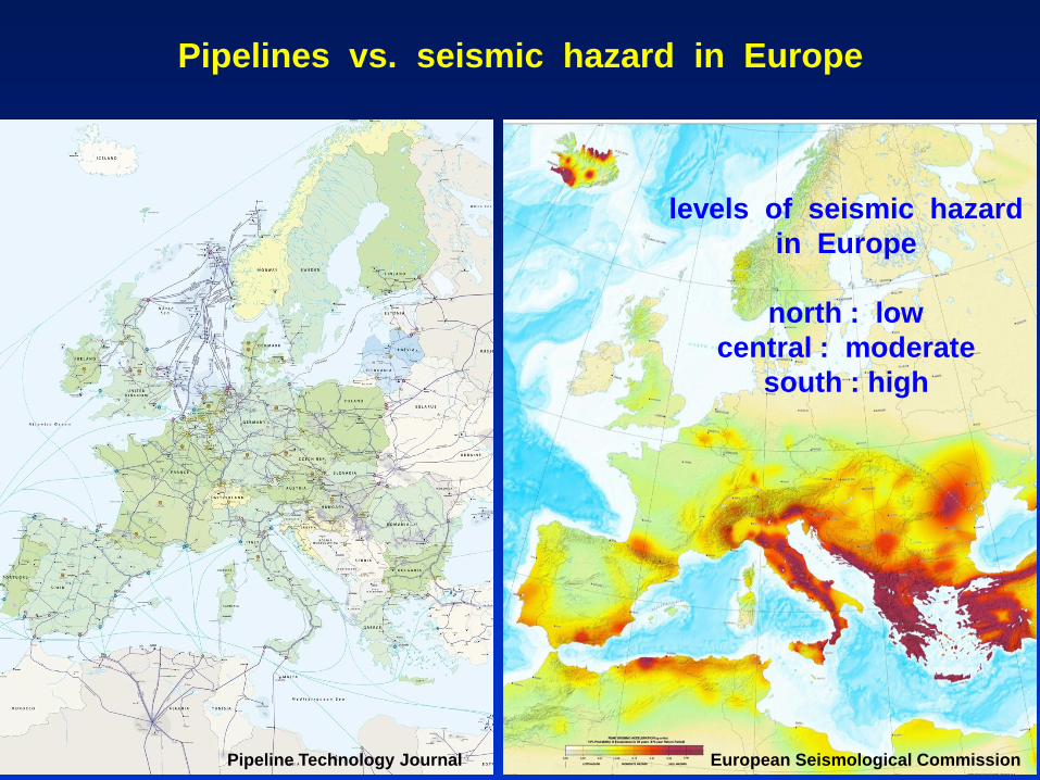
Pipelines vs. seismic hazard in Europe
European Seismological Commission Pipeline Technology Journal
levels of seismic hazard
in Europe
north : low
central : moderate
south : high

low
moderate
high
Global seismic hazard map
in terms of peak ground acceleration at the rock outcrop
Note that local site conditions may alter the picture…
hard rock
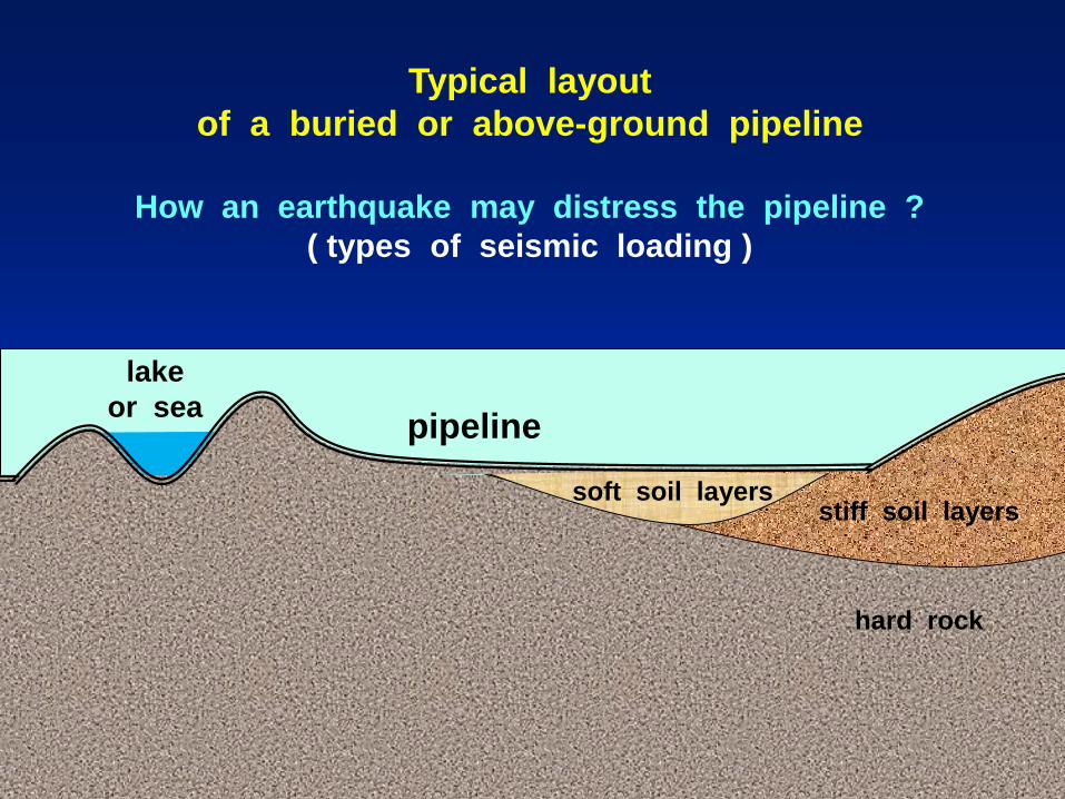
Typical layout
of a buried or above-ground pipeline
How an earthquake may distress the pipeline ?
( types of seismic loading )
stiff soil layers
lake
or sea
soft soil layers
pipeline
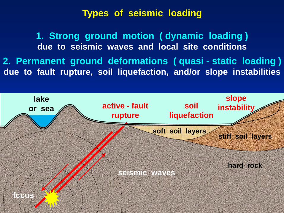
Types of seismic loading
1. Strong ground motion ( dynamic loading ) due to seismic waves and local site conditions
2. Permanent ground deformations ( quasi - static loading ) due to fault rupture, soil liquefaction, and/or slope instabilities
focus
hard rock
active - fault
rupture
stiff soil layers
lake
or sea
soft soil layers
slope
instability soil
liquefaction
seismic waves

hard rock
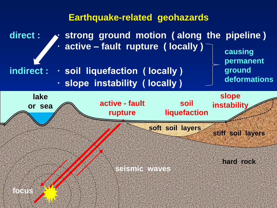
Earthquake-related geohazards
direct : ∙ strong ground motion ( along the pipeline )
∙ active – fault rupture ( locally )
active - fault
rupture
stiff soil layers
lake
or sea
soft soil layers
slope
instability soil
liquefaction
focus
seismic waves
hard rock
Earthquake-related geohazards
direct : ∙ strong ground motion ( along the pipeline )
∙ active – fault rupture ( locally )
indirect : ∙ soil liquefaction ( locally )
∙ slope instability ( locally )
active - fault
rupture
stiff soil layers
lake
or sea
soft soil layers
slope
instability soil
liquefaction
focus
seismic waves
causing
permanent
ground
deformations
Case histories of damaged pipelines
Observed damages of pipelines in the past have shown that
pipelines ( especially the buried ones ) are sensitive to permanent ground deformations (PGDs)
Reminder:
Strong ground motion is an indirect cause of PGDs as it causes ground failures
( i.e. soil liquefaction, slope instability )
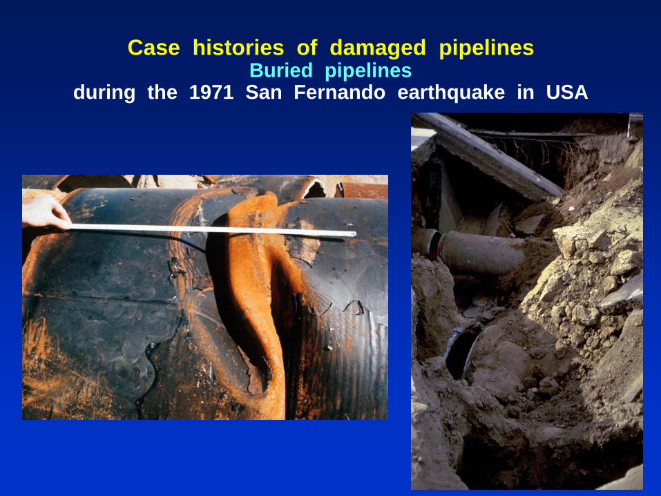
Case histories of damaged pipelines Buried pipelines
during the 1971 San Fernando earthquake in USA

Case histories of damaged pipelines
Fault‐induced damage of a buried pipeline
during the Manjil earthquake 1990, Iran
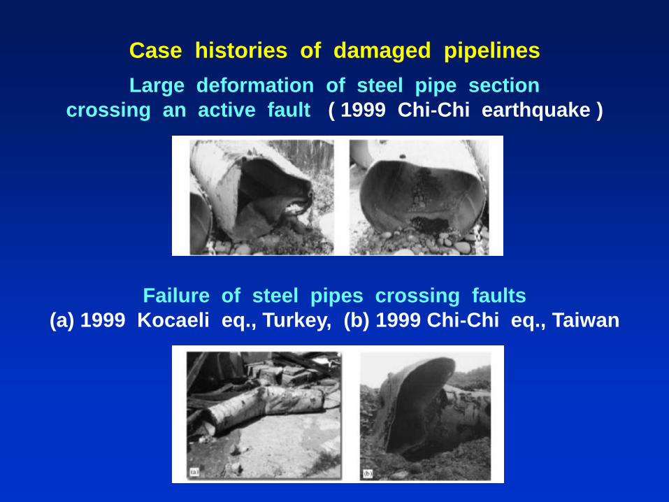
Case histories of damaged pipelines
Large deformation of steel pipe section
crossing an active fault ( 1999 Chi‐Chi earthquake )
Failure of steel pipes crossing faults
(a) 1999 Kocaeli eq., Turkey, (b) 1999 Chi‐Chi eq., Taiwan

Liquefaction-induced failures to concrete pipelines
during the 1993 Nansei-Oki Earthquake ( Japan )
Case histories of damaged pipelines
Presentation Contents
1. Introduction
2. Quantitative assessment and treatment of geohazards
• Strong ground motion
• Active-fault rupture
• Soil liquefaction
• Slope instability
3. Proposals and general conclusions

Structural distress and mitigation measures
Αny structure may be distressed by:
a) external loading, and/or
b) induced permanent ground deformations ( PGDs )
A D C
B A D C B
external
loading p
induced PGD
u

Structural distress and mitigation measures
( Capacity )
( Safety ) =
( Geohazard )
S can be increased by :
a) decreasing G ( by geotechnical mitigation measures ), or
b) increasing C ( by structural mitigation measures ), or
c) decreasing G and increasing C in parallel
( by a combination of geotechnical and structural measures )
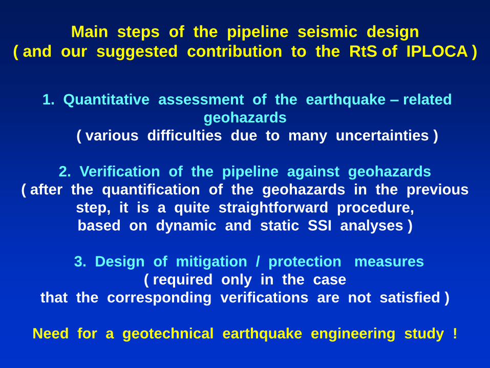
Main steps of the pipeline seismic design
( and our suggested contribution to the RtS of IPLOCA )
1. Quantitative assessment of the earthquake – related
geohazards
( various difficulties due to many uncertainties )
2. Verification of the pipeline against geohazards
( after the quantification of the geohazards in the previous
step, it is a quite straightforward procedure,
based on dynamic and static SSI analyses )
3. Design of mitigation / protection measures
( required only in the case
that the corresponding verifications are not satisfied )
Need for a geotechnical earthquake engineering study !
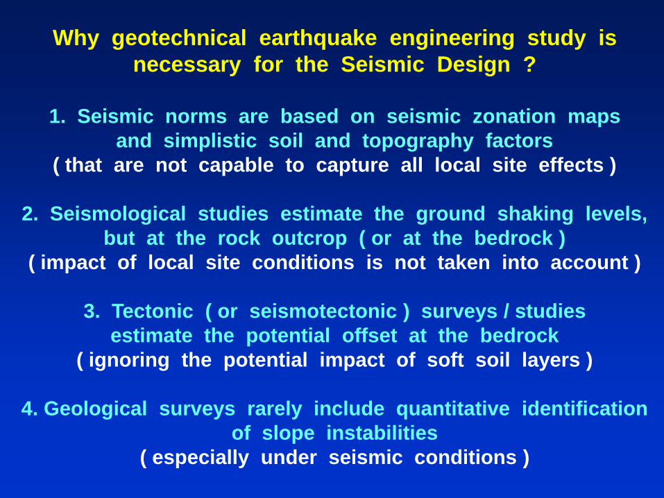
Why geotechnical earthquake engineering study is
necessary for the Seismic Design ?
1. Seismic norms are based on seismic zonation maps
and simplistic soil and topography factors
( that are not capable to capture all local site effects )
2. Seismological studies estimate the ground shaking levels,
but at the rock outcrop ( or at the bedrock )
( impact of local site conditions is not taken into account )
3. Tectonic ( or seismotectonic ) surveys / studies
estimate the potential offset at the bedrock
( ignoring the potential impact of soft soil layers )
4. Geological surveys rarely include quantitative identification
of slope instabilities
( especially under seismic conditions )

Prerequisites of the
geotechnical earthquake engineering study
Topographic ( or bathymetric ) survey
( topographic features of the area under examination )
Geological mapping / survey
( qualitative identification of the potential geohazards )
Tectonic ( or seismotectonic ) survey / study
( active-fault identification and potential offset at bedrock )
Seismological study
( estimation of the acceleration levels at rock outcrop )
Geotechnical ( and geophysical ) study / investigation
( identification of the soil properties / local site conditions )
Presentation Contents
1. Introduction
2. Quantitative assessment and treatment of geohazards
• Strong ground motion
• Active-fault rupture
• Soil liquefaction
• Slope instability
3. Proposals and general conclusions
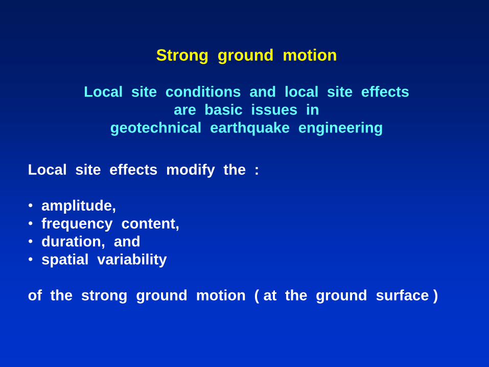
Strong ground motion
Local site conditions and local site effects
are basic issues in
geotechnical earthquake engineering
Local site effects modify the :
• amplitude,
• frequency content,
• duration, and
• spatial variability
of the strong ground motion ( at the ground surface )

rock
soil layer
soil layer
rock
soil
Strong ground motion
Categorization of local site conditions
rock
stratigraphy (1-D)
geomorphology of
the bedrock (2D or 3D) surface topography
(2D or 3D)
note: all of them coexist in nature !
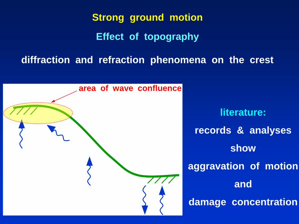
Strong ground motion
Effect of topography
diffraction and refraction phenomena on the crest
area of wave confluence
literature:
records & analyses
show
aggravation of motion
and
damage concentration

< 300 m
Strong ground motion
area 2 area 3
30ο 40 m
heavily damaged
area
1999 Athens eq.

-0.4
-0.2
0
0.2
0.4
0 0.4 0.8 1.2
-0.4
-0.2
0
0.2
0.4
0 0.4 0.8 1.2
-0.4
-0.2
0
0.2
0.4
0 0.4 0.8 1.2
0.10 g
Α
0.29 g 0.37 g
2. Strong ground motion Response to pulse excitation
Α
t
Α
t
0.4
0.2
0
-0.2
-0.4
0.4
0.2
0
-0.2
-0.4
0.2
0.1
0
-0.1
-0.2
0 0.4 0.8 1.2 t
0 0.4 0.8 1.2 0 0.4 0.8 1.2
Ricker
pulse

x
x (m)
H
H
2 - D
1 - D
a
a
Strong ground motion
Spatial variability of topographic aggravation
horizontal motion at the ground surface
1.5
1.0
0.5
0
300 200 100 0
0
0.5
1.0
1.5
0100200300

x : m
x : m
y : m
a m
ax :
g amax : g
Assessment of local site effects ( topography and soil )
( prerequisite for the slope stability assessment )
Acceleration distribution along a slope of IGI-Poseidon
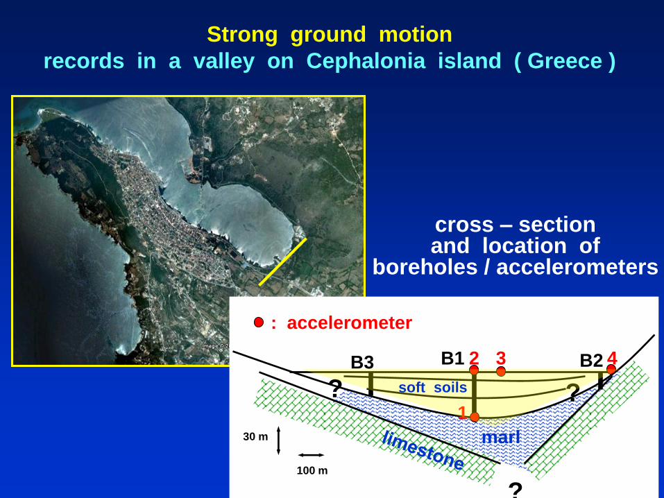
cross – section and location of
boreholes / accelerometers
Strong ground motion
records in a valley on Cephalonia island ( Greece )
100 m
30 m marl
B3 B1 B2
: accelerometer
2 3 4
1
?
? ? soft soils

4E
1E
3E2E
100 m30 m
Vs = 250 m/s
Vs = 320 m/s
Vs = 150 m/s
MARLVs = 500 m/s
Vs = 1000-1500 m/s
LIMESTONE
Strong ground motion
records in a valley on Cephalonia island ( Greece )
EF4E
-240
-160
-80
0
80
160
240
0 2 4 6 8 10t : seca
: c
m/s
/s
EF1E
-240
-160
-80
0
80
160
240
0 2 4 6 8 10t : sec
a :
cm
/s/s
1
4
EF3E
-240
-160
-80
0
80
160
240
0 2 4 6 8 10t : sec
a :
cm
/s/s
EF2E
-240
-160
-80
0
80
160
240
0 2 4 6 8 10t : sec
a :
cm
/s/s
2 3 0.24 g
0.04 g
0.06 g
substantial amplification: AF ≈ 4
( PGSA : 0.24g vs. PGBA : 0.06g )
spatial variability on the surface
( 0.24g vs. 0.04g )
0.24 g

Strong ground motion
Main danger of valley amplification
small earthquake ( linear soil behavior ) :
PGBA ≈ 0.06g & AF ≈ 4 → PGSA ≈ 0.24g
moderate earthquake ( non-linear soil behavior ) :
PGBA ≈ 0.12g & AF ≈ 2 → PGSA ≈ 0.24g
strong earthquake ( very non-linear soil behavior ) :
PGBA ≈ 0.24g & AF ≈ 1 → PGSA ≈ 0.24g
Note: due to local site conditions a moderate ( or even a small earthquake ) may lead to surface acceleration levels comparable to them of a strong earthquake

Strong ground motion
In areas characterized
by moderate seismicity the seismic risk may be high
( depending on the circumstances )
low
moderate
high

Verification against strong ground motion
Should be based on the
estimation of the maximum developed strains for both the
pipeline straight sections and the pipeline bends.
According to the current state of practice,
the strains induced due to seismic wave propagation
on the pipeline
could be calculated utilizing the analytical methods
described in the corresponding design guidelines / provisions,
as well as in the relative literature.

Presentation Contents
1. Introduction
2. Quantitative assessment and treatment of geohazards
• Strong ground motion
• Active-fault rupture
• Soil liquefaction
• Slope instability
3. Proposals and general conclusions

Active-fault rupture
Categorization of active faults
depending on the tectonic movement
normal
( tension )
reverse
( compression )
strike-slip
( shear )

Categorization of active faults
depending on their location and the geological conditions:
a) outcropped
b) covered ( blind )
Note:
The rupture of an outcropped fault is
a direct threat to a crossing pipeline,
while in a covered fault the ground ( or seabed ) conditions
may alter the fault rupture propagation and the PGD
pattern at the ground surface ( or seafloor ).
Assessment of PGDs due to fault rupture
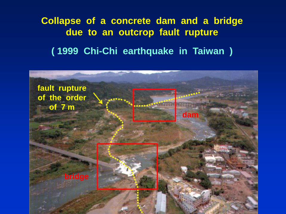
Collapse of a concrete dam and a bridge
due to an outcrop fault rupture
( 1999 Chi-Chi earthquake in Taiwan )
fault rupture
of the order
of 7 m
bridge
dam
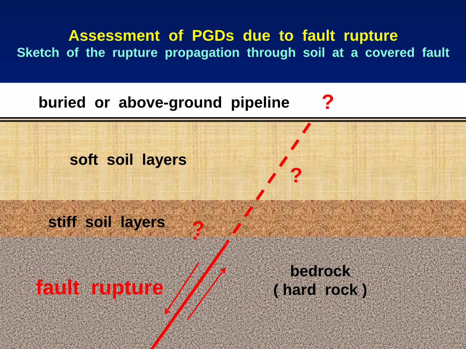
bedrock
( hard rock )
soft soil layers
stiff soil ? stiff soil layers
buried or above-ground pipeline
?
fault rupture
?
?
Assessment of PGDs due to fault rupture Sketch of the rupture propagation through soil at a covered fault
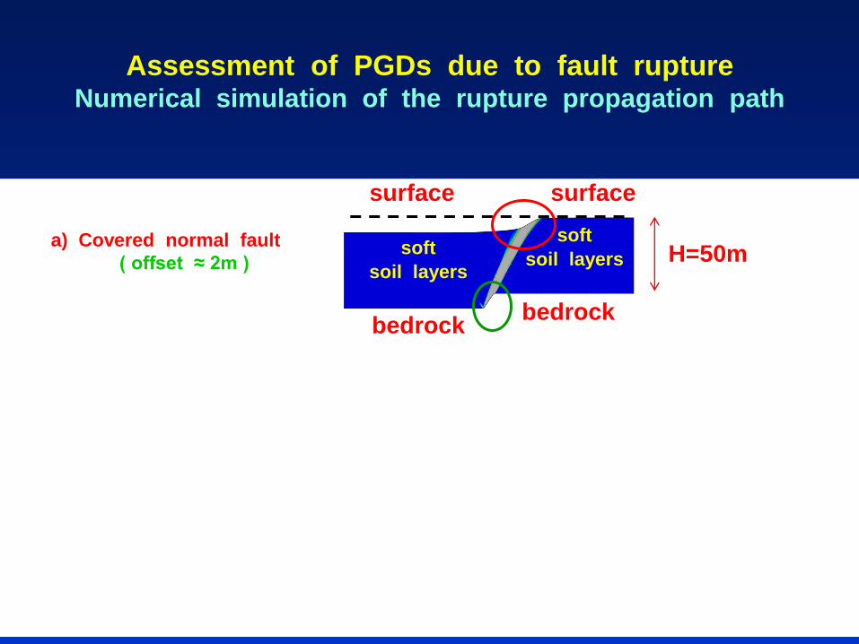
Assessment of PGDs due to fault rupture Numerical simulation of the rupture propagation path
a) Covered normal fault
( offset ≈ 2m ) soft
soil layers
bedrock
H=50m
surface
soft soil layers
bedrock
surface

Assessment of PGDs due to fault rupture Numerical simulation of the rupture propagation path
soft
soil layers
b) Covered reverse fault
( offset ≈ 2m )
a) Covered normal fault
( offset ≈ 2m ) soft
soil layers
bedrock
bedrock
H=80 m
H=50m
surface
soft soil layers
bedrock
bedrock
surface surface
surface

The pattern of PGDs at the surface depends on:
a) the geometrical and mechanical properties of geomaterials,
b) the fault type, and
c) the induced offset at the bedrock
Note:
The PGDs will be the imposed displacements to the pipeline
( as a quasi – static loading )
Assessment of PGDs due to fault rupture Numerical simulation of the rupture propagation path

Verification of a pipeline
crossing an active outcrop fault
FEED phase of Italy-Greece Interconnector (IGI) – Poseidon
excessive strains &
need for mitigation measures

Mitigation measures for active-fault rupture
In case of excessive pipeline strains due PGDs,
the following mitigation measures should be adopted :
a) an increase in pipe wall thickness
b) reduction of the angle of interface friction between the
pipeline and the soil. The reduction of the angle of interface
friction may be achieved through various techniques
c) backfilling the surrounding of the pipeline with a loose to
medium granular soil without cobbles or boulders.
The backfill could be either soil or a synthetic smooth
material with similar mechanical behavior
d) construction of a soft embankment above the fault
The final solution(s) should be verified in order the pipeline
to comply with the strain limits imposed by the norms

Mitigation measures for active-fault rupture
If a slight relocation of the pipeline is possible,
then the pipeline crossing a fault should be oriented in such
a way as to place the pipeline in tension
( and not in compression )
Additionally,
in fault zones the depth at which the pipeline is buried
should be minimized
in order to reduce soil restraint on the pipeline
during fault movement
Mitigation measures for active-fault rupture
Important note:
If the final solution proposes exclusively modifications of the
pipeline mechanical and/or geometrical properties,
the pipeline should be re-verified to comply with the strain
limits imposed by the norms and standards
Otherwise, in the case of new backfill,
a re-assessment of the fault rupture propagation
should have preceded of any pipeline re-verification
in order to estimate the impact of the backfill material
properties on the PGDs at the ground surface
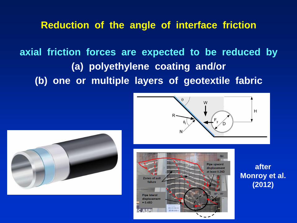
Reduction of the angle of interface friction
axial friction forces are expected to be reduced by
(a) polyethylene coating and/or
(b) one or multiple layers of geotextile fabric
after
Monroy et al.
(2012)

Mitigation measures
soft embankment above the trace of an outcrop fault
in the cases of a normal and a reverse active fault
normal fault 45ο
reverse fault 45ο
wide fault zone
narrow fault zone

Mitigation measures applied for IGI-Poseidon pipeline that crosses an active fault
( oversized trench )
fau
lt t
race
normal trench
oversized trench
normal trench
pipe
15 m 15 m
normal
trench
oversized trench
ground level
pipe
4 m
5 m
plan view
cross section
a loose to medium granular
soil (e.g. fine sand) without
cobbles or boulders in an
L =
S =
D = rock
Note: the width of fault zone W
(trace) has to be defined

A famous example of an innovative
( and successful ) pipeline seismic design
2002 Denali – Alaska earthquake :
seismic isolation of the Trans-Alaska pipeline against
the rupture of a pre-existing active strike – slip fault
The special footings allow the pipe to move
6m laterally and 1.5m vertically

Presentation Contents
1. Introduction
2. Quantitative assessment and treatment of geohazards
• Strong ground motion
• Active-fault rupture
• Soil liquefaction
• Slope instability
3. Proposals and general conclusions

Soil liquefaction phenomena
Soil liquefaction is
an extreme consequence of strong ground motion
which leads to
practically total loss of shear strength
in relatively loose cohesionless soil formations
below the water table

Soil liquefaction phenomena
a) Uplifting and liquefaction-induced settlements
( i.e. almost vertical PGDs )
b) Lateral spreading
( i.e. almost horizontal PGDs )
1999 Izmit earthquake
( Turkey )
2011 Christchurch earthquake
( N. Zealand )

Assessment of PGDs
of soil liquefaction phenomena
In the literature
there exist various analytical and empirical methods
for the realistic estimation
of vertical and horizontal PGDs

Mitigation measures for lateral spreading
In the case of excessive lateral spreading,
the “isolation” of the pipeline
from the damaging horizontal PGDs can be achieved by:
re-routing or HDD method
In case of lateral spreading being developed
in a relatively small ( spatially ) area,
an alternative solution is to apply retaining structures,
such as bored-pile walls or sheet-pile walls.

Mitigation measures for uplifting
Concrete coating, rings or other anchoring systems
should be installed
in order to avoid the pipeline uplifting
due to pore-pressure built-up

Mitigation measures for vertical PGDs
In areas where the distress of the pipeline
due to vertical PGDs is excessive,
there are three commonly-used methodologies
to protect the pipeline:
a) reduce PGDs by various means,
b) increase the pipe wall thickness,
c) “isolate” the pipeline from the damaging PGDs
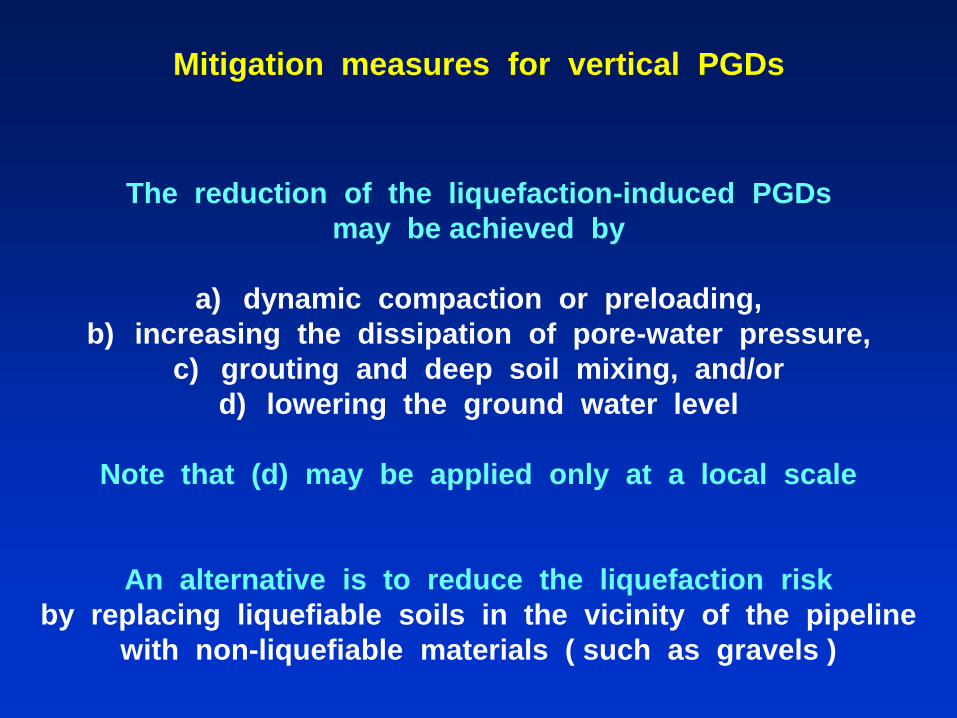
Mitigation measures for vertical PGDs
The reduction of the liquefaction-induced PGDs
may be achieved by
a) dynamic compaction or preloading,
b) increasing the dissipation of pore-water pressure,
c) grouting and deep soil mixing, and/or
d) lowering the ground water level
Note that (d) may be applied only at a local scale
An alternative is to reduce the liquefaction risk
by replacing liquefiable soils in the vicinity of the pipeline
with non-liquefiable materials ( such as gravels )

Mitigation measures for vertical PGDs
In the cases where the aforementioned methods
are considered as inappropriate,
the placement of the pipeline below the hazardous area
( achieved by horizontal directional drilling – HDD )
is a more practical methodology
( apart from rerouting )
Note that, if the final solution proposes the isolation of the
pipeline, there is no need for re-verification of the pipeline
for liquefaction.
In any other case a re-assessment of the improved
mechanical soil properties should have preceded of any
pipeline re-verification.
Presentation Contents
1. Introduction
2. Quantitative assessment and treatment of geohazards
• Strong ground motion
• Active-fault rupture
• Soil liquefaction
• Slope instability
3. Proposals and general conclusions

Slope instabilities under static and seismic conditions
and pipeline distress - failures
Many static ( as well as seismic ) slope instabilities
have been observed worldwide in the past.
Nevertheless, few pipeline failures have been recorded
during only static slope instabilities.
This is attributed to the fact that up to date very
limited pipelines have been constructed
in mountainous areas characterized by high seismicity.
The pipeline construction
on a high slope subjected to seismic loading may lead to
pipeline failure due to earthquake-triggered slope instabilities
( i.e. pre-existing landslides or first-time slope failures )
( unless appropriate seismic design has been adopted ).
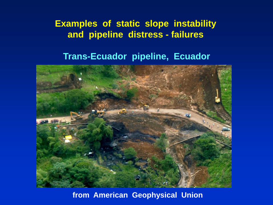
Examples of static slope instability
and pipeline distress - failures
Trans-Ecuador pipeline, Ecuador
from American Geophysical Union

Examples of static slope instability
and pipeline distress - failures
Camisea pipeline, Peru
after Lee et al. 2009
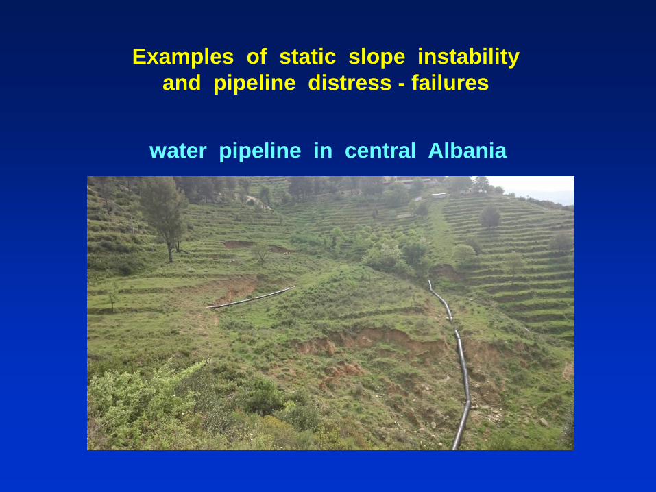
Examples of static slope instability
and pipeline distress - failures
water pipeline in central Albania
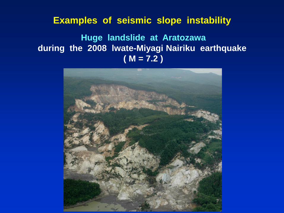
Examples of seismic slope instability
Huge landslide at Aratozawa
during the 2008 lwate-Miyagi Nairiku earthquake
( M = 7.2 )

Examples of seismic slope instability
Great mountainous landslides
caused by the 2008 Wenchuan earthquake in southwest China
( Mw = 7.9 )

Examples of seismic slope instability
two landslides during the 2014 earthquake on Cefalonia island, Greece
( Μ = 6 )

Slope instability and pipeline distress:
a soil – structure interaction problem
If pipeline routing is parallel to the induced PGD,
the pipeline is subjected to tension and compression
If the pipeline is transverse to the induced PGD,
the pipeline is subjected to bending
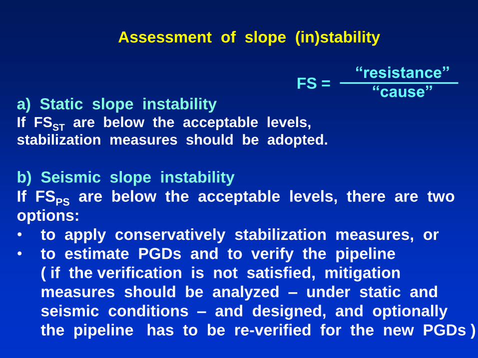
Assessment of slope (in)stability
a) Static slope instability If FSST are below the acceptable levels,
stabilization measures should be adopted.
b) Seismic slope instability
If FSPS are below the acceptable levels, there are two
options:
• to apply conservatively stabilization measures, or
• to estimate PGDs and to verify the pipeline
( if the verification is not satisfied, mitigation
measures should be analyzed – under static and
seismic conditions – and designed, and optionally
the pipeline has to be re-verified for the new PGDs )
FS = “resistance”
“cause”

Modern philosophy of seismic design
(a) earthquakes are accidental phenomena
with an estimated possibility of occurrence
(b) most of the steel pipelines may accommodate
certain levels of strain without failure ( i.e. rupture )
Therefore, a balance between safety and economy
may be achieved by applying
the concept of “strain – based design” and
the “modern philosophy of seismic design”,
according to which repairable damages to a structure
( i.e. exceedance of yield strain ) may be allowed or
accepted in the case of the design earthquake,
provided that the non-failure requirement has been
fulfilled ( i.e. non exceedance of failure strain ).
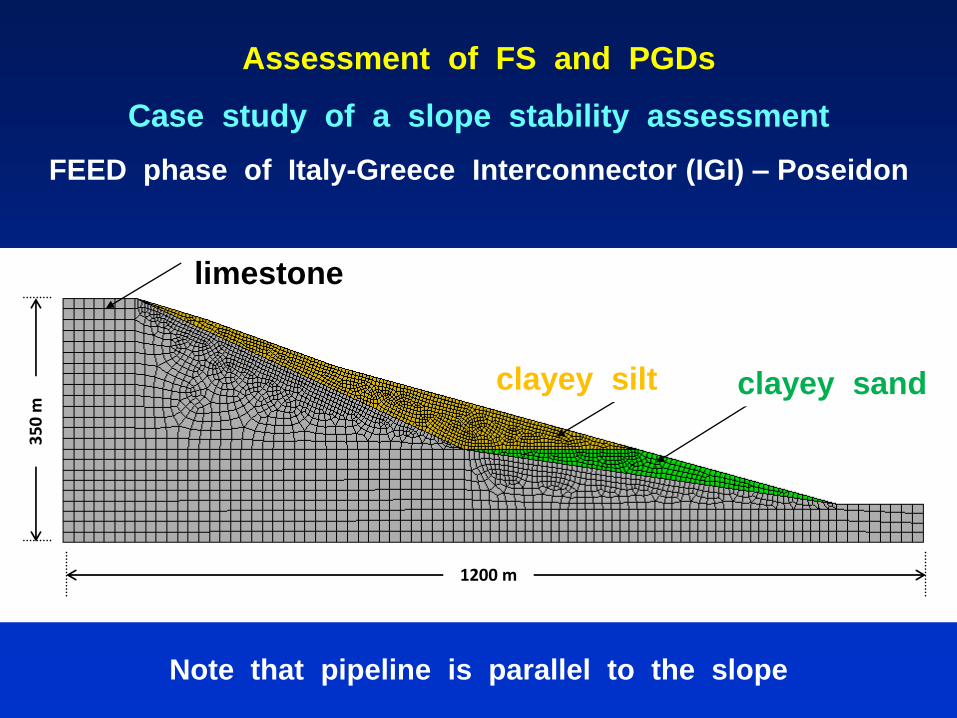
1200 m
35
0 m
clay – silt clayey sand
limestone
Assessment of FS and PGDs
Case study of a slope stability assessment
FEED phase of Italy-Greece Interconnector (IGI) – Poseidon
limestone
clayey silt clayey sand
Note that pipeline is parallel to the slope
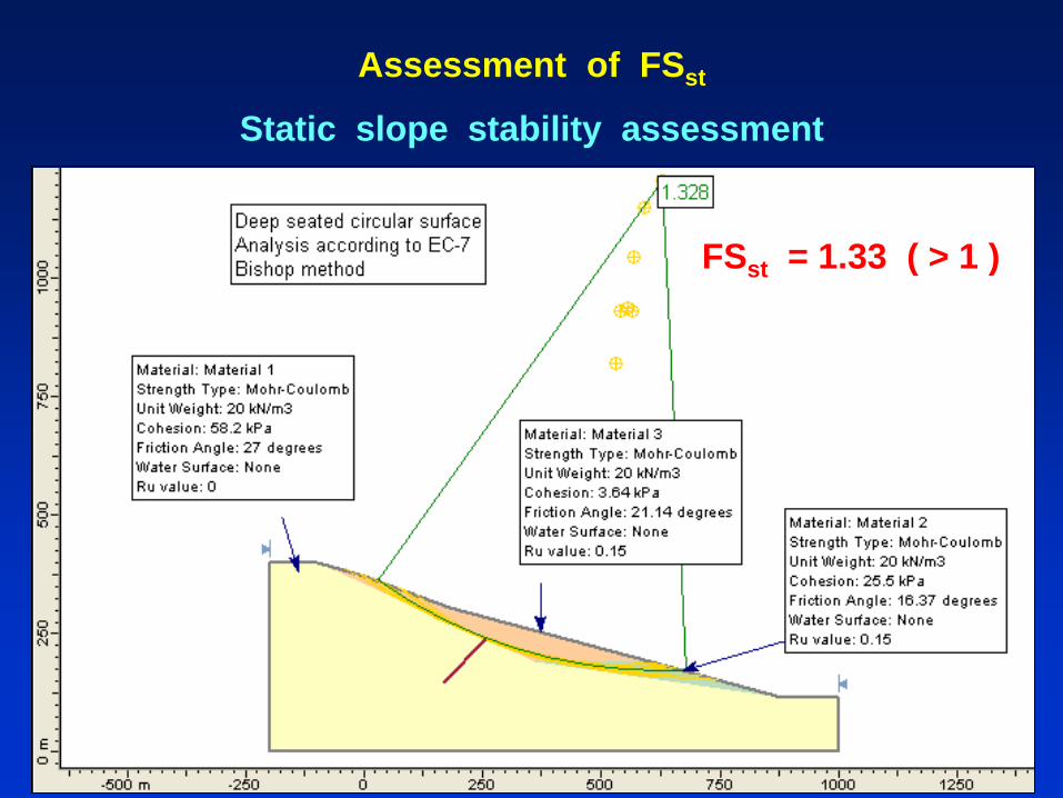
Assessment of FSst
Static slope stability assessment
FSst = 1.33 ( > 1 )

Assessment of FSps
Pseudo – static slope stability assessment
ULS ( TR = 2475 yr )
Ah = 0.30g & Av = + 0.15g FSps = 0.80
Ah = 0.30g & Av = - 0.15g FSps = 0.65
DLS ( TR = 475 yr )
Ah = 0.20g & Av = + 0.10g FSps = 0.96
Ah = 0.20g & Av = - 0.10g FSps = 0.86
Since FSPS < 1 in all cases, slope may be regarded as
unstable and stabilization measures may be applied

Assessment of slope instability
seismic ( dynamic ) slope stability assessment
estimation of AC ( A that corresponds to FSPS = 1 )
AC = 0.16g

-0.3
-0.2
-0.1
0
0.1
0.2
0.3
0 1 2 3 4 5 6 7 8 9 10
1985 Kalamata eq.,
Greece
-0.3
-0.2
-0.1
0
0.1
0.2
0.3
0 2 4 6 8 10 12 14 16 18 20
-0.3
-0.2
-0.1
0
0.1
0.2
0.3
0 5 10 15 20 25
Assessment of slope instability
selected excitations ( recorded time histories )
1973 Lefkada eq.,
Greece
1999 Duzce eq.,
Turkey
( all scaled to 0.25g )

kala
mata
lefk
ad
ad
uzce
model S3 – DLS – circular deep
kala
mata
lefk
ad
ad
uzce
model S3 – DLS – circular deep
Assessment of slope instability
Seismic slope stability assessment
ULS: PGD = 27 cm DLS: PGD = 9 cm
At the verification phase it was examined ( with SSI analyses )
whether the pipeline under design
is capable to withstand these deformations.
Finally, no stabilization measures are required.
kala
mata
lefk
ad
ad
uzce
model S3 – ULS – circular deep
kala
mata
lefk
ad
ad
uzce
model S3 – ULS – circular deep

Assessment of slope instability
According to the
guidelines of California Geological Survey ( CGS, 2008 )
for evaluating and mitigating seismic hazards,
referring to slope movements:
PGDs < 15 cm
no serious slope movement, slope is regarded stable
PGDs > 100 cm
slope is regarded unstable
15 cm < PGDs < 100 cm
requires good engineering judgment
( in the case of a pipeline, verification is required )
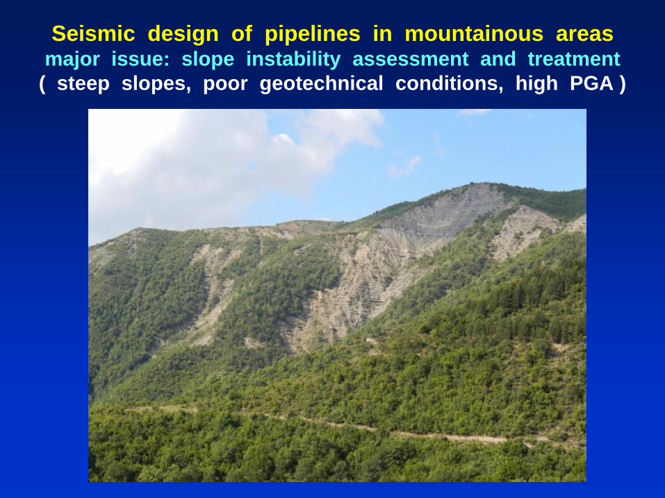
Seismic design of pipelines in mountainous areas major issue: slope instability assessment and treatment
( steep slopes, poor geotechnical conditions, high PGA )

Seismic design of pipelines in mountainous areas
seismic slope stability analysis
if instability is located on the ground surface
topography effects are important
( light stabilization measures )
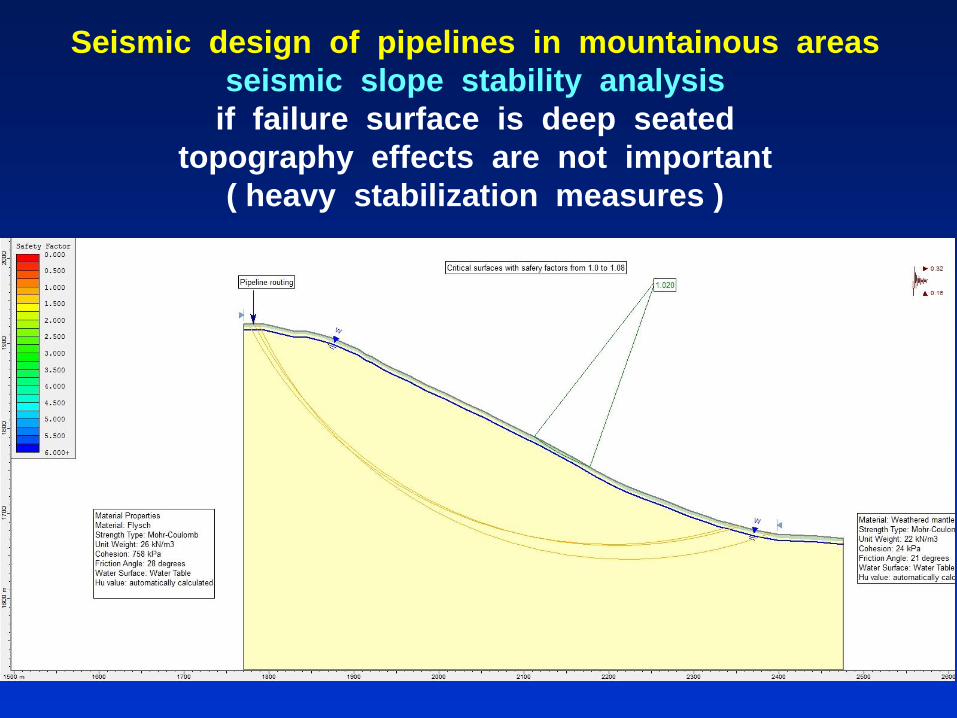
Seismic design of pipelines in mountainous areas
seismic slope stability analysis
if failure surface is deep seated
topography effects are not important
( heavy stabilization measures )
Given the special characteristics of the problematic area,
the selection of the optimum mitigation measure
should take into consideration various parameters
( e.g. environmental impact, constructability, accessibility,
cost, etc. )
The very final geometrical and mechanical properties
of any adopted measure,
along with its impact on the pipeline distress,
should be verified by detailed geotechnical investigation
and simulations on a case-by-case basis
Potential mitigation measures
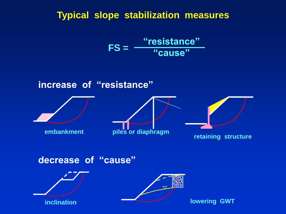
Typical slope stabilization measures
FS = “resistance”
“cause”
decrease of “cause”
lowering GWT inclination
embankment piles or diaphragm retaining structure
increase of “resistance”
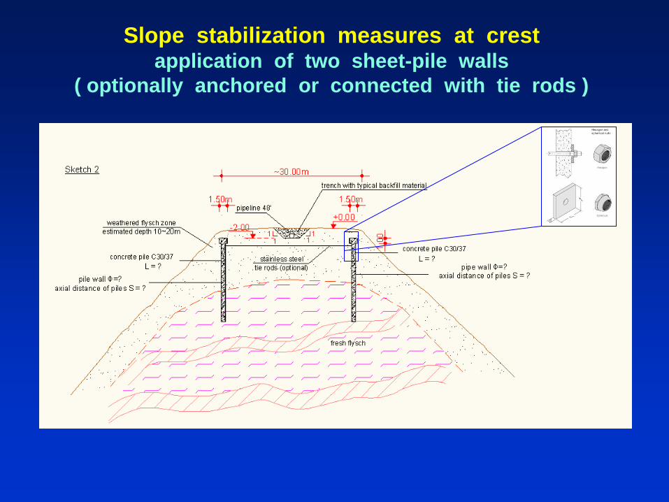
Slope stabilization measures at crest application of two sheet-pile walls
( optionally anchored or connected with tie rods )

Slope stabilization measures at crest application of passive anchors,
optionally with piles underneath the pipe

Modern philosophy of seismic design
Repairable damages to any structure are allowed,
provided that the non-collapse requirement
has been fulfilled.
Nevertheless, since the mainshock may have caused
serious damages to the pipeline, the pipeline may be
vulnerable even to an aftershock of smaller magnitude
Therefore, field monitoring would help to identify
immediately the pipeline damages due to a strong
earthquake in order to repair it as fast as possible.
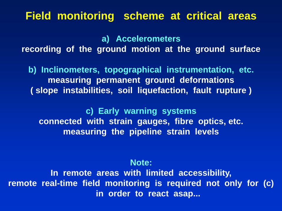
Field monitoring scheme at critical areas
a) Accelerometers
recording of the ground motion at the ground surface
b) Inclinometers, topographical instrumentation, etc.
measuring permanent ground deformations
( slope instabilities, soil liquefaction, fault rupture )
c) Early warning systems
connected with strain gauges, fibre optics, etc.
measuring the pipeline strain levels
Note:
In remote areas with limited accessibility,
remote real-time field monitoring is required not only for (c)
in order to react asap...

Presentation Contents
1. Introduction
2. Quantitative assessment and treatment of geohazards
• Strong ground motion
• Active-fault rupture
• Soil liquefaction
• Slope instability
3. Proposals and general conclusions

Traditional practice against geohazards
1. Avoidance of the problematic area(s)
by pipeline re-routing ( horizontally or vertically )
Note that it is not always feasible
due to various technical and/or environmental constraints
( or even time limitations )
2. Various geotechnical mitigation measures
aiming to minimize the expected PGDs
Usually geotechnical mitigation measures have a substantial
cost, depending on the geohazard type and extent
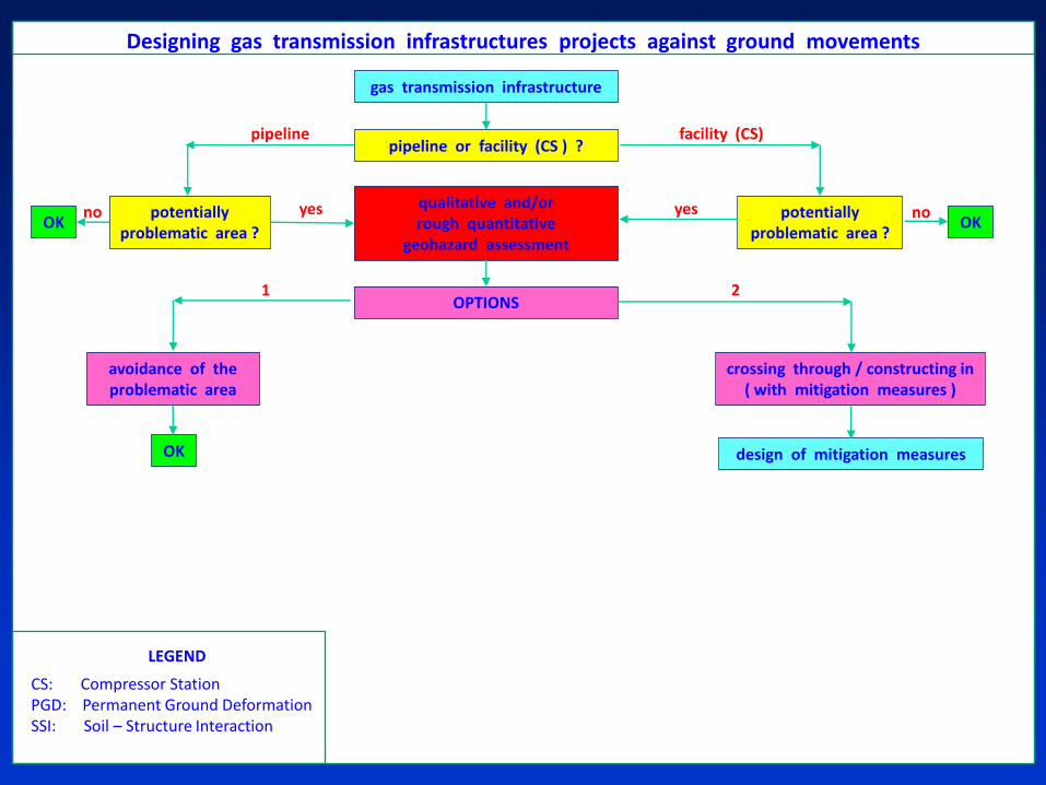
no OK
yes no
gas transmission infrastructure
pipeline or facility (CS ) ?
potentially problematic area ?
OK qualitative and/or rough quantitative
geohazard assessment
yes potentially problematic area ?
pipeline facility (CS)
OPTIONS
avoidance of the problematic area
crossing through / constructing in ( with mitigation measures )
OK design of mitigation measures
1 2
LEGEND
CS: Compressor Station PGD: Permanent Ground Deformation SSI: Soil – Structure Interaction
Designing gas transmission infrastructures projects against ground movements
Modern practice against geohazards
A third option
may be the most cost-effective in many cases:
3. Crossing through the problematic area(s)
without mitigation measures
( provided that pipeline has been checked that it is capable
to accommodate the expected PGDs )

Modern practice against geohazards
In the case of the third option
the design should include:
a) Detailed PGD assessment, and
b) Soil – structure interaction analyses,
in order to assess the structural capability of the structure
under examination to accommodate the expected PGDs
( “strain-based design” )
Basic prerequisites:
a) Specifications and supervision
in order to achieve in practice the high-strain capacity
b) Monitoring of the geohazard and the structure (i.e. pipeline)
simultaneously

no
yes
no OK
yes no
gas transmission infrastructure
pipeline or facility (CS) ?
potentially problematic area ?
OK rough PGD assessment and
preliminary SSI analyses
yes potentially problematic area ?
pipeline facility (CS)
OPTIONS
avoidance of the problematic area
crossing through / constructing in ( without mitigation measures )
crossing through / constructing in ( with mitigation measures )
OK design of mitigation measures
advanced SSI analyses
acceptable strain ? ( strain -based design )
detailed PGD assessment
OK (with monitoring)
no
1
3
2
LEGEND
CS: Compressor Station PGD: Permanent Ground Deformation SSI: Soil – Structure Interaction
Designing of gas transmission infrastructures projects against ground movements
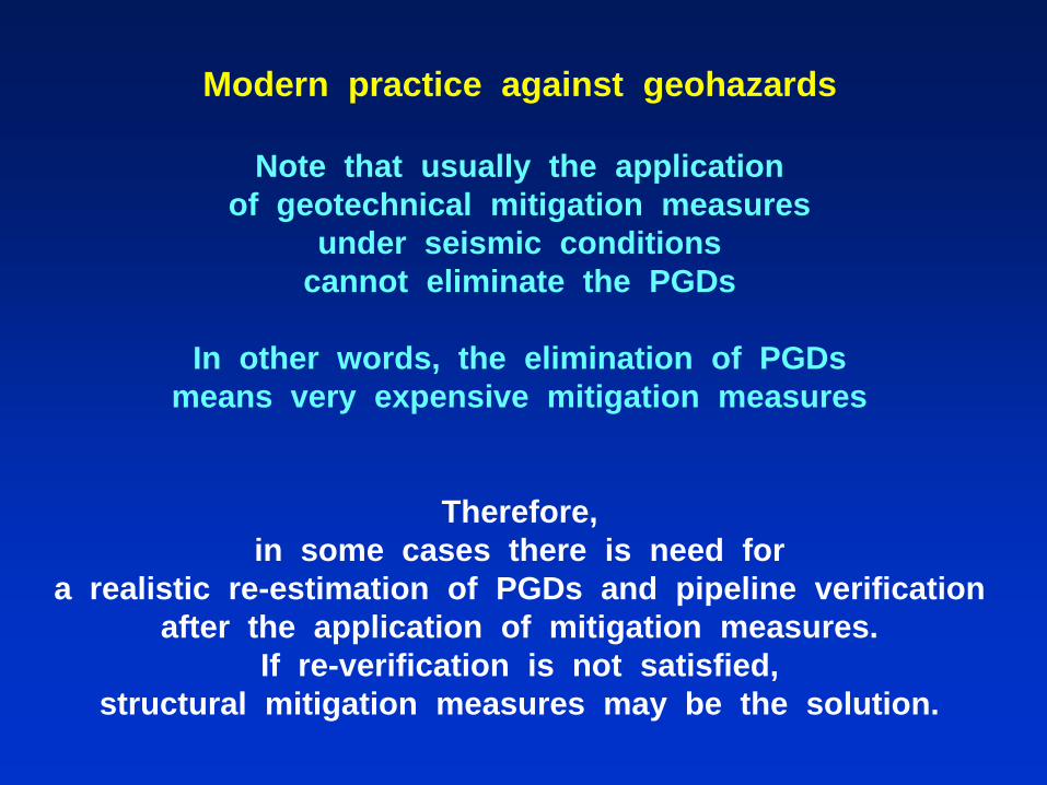
Modern practice against geohazards
Note that usually the application
of geotechnical mitigation measures
under seismic conditions
cannot eliminate the PGDs
In other words, the elimination of PGDs
means very expensive mitigation measures
Therefore,
in some cases there is need for
a realistic re-estimation of PGDs and pipeline verification
after the application of mitigation measures.
If re-verification is not satisfied,
structural mitigation measures may be the solution.
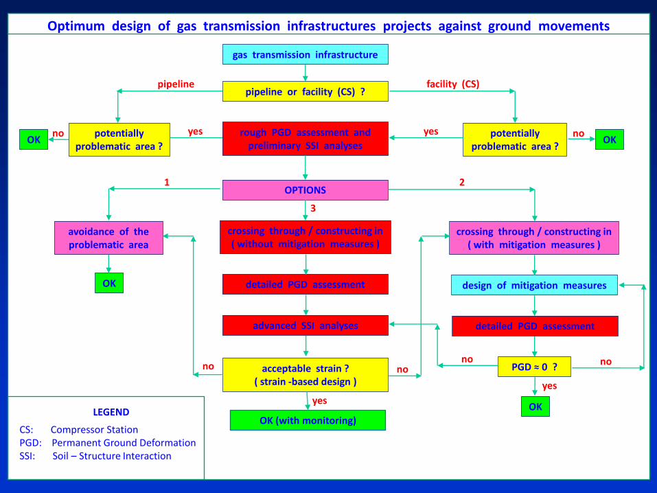
no
yes
no OK
yes no
gas transmission infrastructure
pipeline or facility (CS) ?
potentially problematic area ?
OK rough PGD assessment and
preliminary SSI analyses
yes potentially problematic area ?
pipeline facility (CS)
OPTIONS
avoidance of the problematic area
crossing through / constructing in ( without mitigation measures )
crossing through / constructing in ( with mitigation measures )
OK design of mitigation measures
advanced SSI analyses
acceptable strain ? ( strain -based design )
detailed PGD assessment
PGD ≈ 0 ?
detailed PGD assessment
OK (with monitoring)
yes
OK
no
1
3
2
no no
LEGEND
CS: Compressor Station PGD: Permanent Ground Deformation SSI: Soil – Structure Interaction
Optimum design of gas transmission infrastructures projects against ground movements

General conclusions ( 1 / 2 )
Earthquake-related geohazards
are potentially serious threats to
all new or existing onshore and offshore pipelines
( and the related infrastructures )
The simplistic provisions
of the seismic standards / norms
are rather incapable to cover sufficiently
all the issues of the seismic design of pipelines
The realistic estimation of
(a) strong ground motion, and
(b) permanent ground deformations
is a prerequisite for reliable pipeline seismic design
The seismic design of pipelines
( and the design of mitigation measures )
is a demanding step of engineering design
( especially when cost-effectiveness is desired )
It requires reliable data and realistic modeling of
the pipeline, the soil, and the soil-pipeline interaction
General conclusions ( 2 / 2 )
Thank you very much
for your attention
Prodromos PSARROPOULOS Geotechnical Earthquake Engineer, M.Sc., Ph.D.