Embed Size (px)
Citation preview

Assessment of Impacts on Radar/IR Assessment of Impacts on Radar/IR Detection Vulnerability and EA/ISR Detection Vulnerability and EA/ISR
EffectivenessEffectiveness
Prof Ken DavidsonProf Ken DavidsonDepartment of MeteorologyDepartment of Meteorology
Root 231Root 231
19 January 2006\19 January 2006\

Propagation ModelsEM: APMIR: EOSTAR
Continuous, 3-D RefractivityExtinctionScintillation
Near-Surface Collected:
Vessel / Buoy Airflow Waves
Atmospheric Numerical Predictions:
Mesoscale
COAMPS
Satellite sensor collected:
Duct Top Height SST
In situ Upper-Air Soundings:
Rawinsondes Microwave/Lidar
Upper-Air COAMPS profilesDuct Fields
= examined/applied
Near-Surface NPS Bulk Model
Wireless Link LandIR
Sea
RF
100%
80%
60%
30%
0%
100%
Effects Models AREPS TAWS
Integrated Approach for RF/IR Impact Assessment:Integrated Approach for RF/IR Impact Assessment:
Capabilities Location When
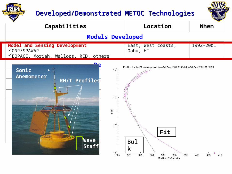
Models DevelopedModel and Sensing Development ONR/SPAWAREOPACE, Moriah, Wallops, RED, others
East, West coasts, Oahu, HI
1992-2001
Demonstrated
Developed/Demonstrated METOC Technologies Developed/Demonstrated METOC Technologies
RH/T Profiles
WaveStaff
Sonic Anemometer
Bulk
Fit

Capabilities Location When
Models DevelopedModel and Sensing Development ONR/SPAWAREOPACE, Moriah, Wallops, RED, others
East, West coasts, Oahu, HI
1992-2001
Demonstrated
Developed/Demonstrated METOC Technologies Developed/Demonstrated METOC Technologies
RH/T Profiles
WaveStaff
Sonic Anemometer
Capabilities Location When
DevelopedModel and Sensing Development ONR/SPAWAR (EOPACE, Moriah, Wallops, RED, others)
East, west coasts, Oahu, HI 1992-2001
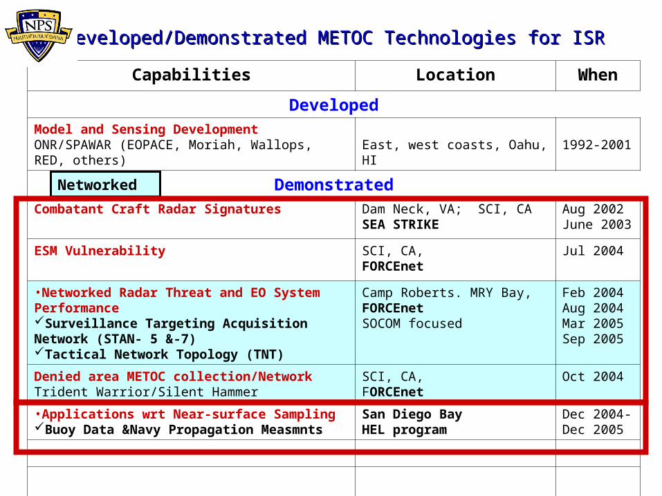
DemonstratedCombatant Craft Radar Signatures Dam Neck, VA; SCI, CA
SEA STRIKEAug 2002 June 2003
ESM Vulnerability SCI, CA, FORCEnet
Jul 2004
•Networked Radar Threat and EO System Performance Surveillance Targeting Acquisition Network (STAN- 5 &-7) Tactical Network Topology (TNT)
Camp Roberts. MRY Bay, FORCEnet SOCOM focused
Feb 2004Aug 2004 Mar 2005Sep 2005
Denied area METOC collection/NetworkTrident Warrior/Silent Hammer
SCI, CA, FORCEnet
Oct 2004
•Applications wrt Near-surface Sampling Buoy Data &Navy Propagation Measmnts
San Diego BayHEL program
Dec 2004- Dec 2005
Developed/Demonstrated METOC Technologies for ISRDeveloped/Demonstrated METOC Technologies for ISR
Networked

Experiment Area & Measurement Points
NPS Buoy
7.2 km path
IR Detector
IR Source

NPS Buoy Deployments
1) 1 Dec 04 – 9 Mar 05
2) 17 Mar 05 - 6 Jun 05
3) 9 Jun 05 – 25 Jul 05
4) 27 Jul 05 – 17 Oct 05
5)20 Oct 05 – ~15 Dec 05

Propagation Loss for Standard AtmospherePropagation Loss for Standard Atmosphere
M increases with height
Effects

Predicts atmospheric properties that affect radar propagation (modified refractivity profile) from basic met measurements
NPS Evaporation Duct Model
Measured parameters (WS, Tair, Tsea, RH)
Evap Duct
Height
Radar waves bend down
Radar waves bend up
NPS Model computes profiles

Propagation Loss for Evaporation DuctPropagation Loss for Evaporation Duct
Greatly Increased Detection Ranges Possible
Duct Ht = 65 ft, radar @ 55 ft
Duct
Effects

Effects of Different Ducting Types on Radar Detection EVS Test Example, SCI, 17 July 2004

Propagation Loss for Surface-Based DuctPropagation Loss for Surface-Based Duct
Skip Zone
Increased Detection Ranges Possible
Top of Trapping Layer
Duct

No Skip Zone
Complex Interference Zone
Sfc-Based Duct
EvapDuct
Propagation Loss for Evaporation & Propagation Loss for Evaporation & Surface-Based DuctsSurface-Based Ducts
Effects

Rf Effects Field Tests with Propagation, Observed and Satellite/COAMPS Data
Location / Year Field Test / Exercise COAMPS Data Source
1) Wallops Island, VA, 2000
NAVSEA Spy-1 Radar TestsNAVSEA/ONR
NRL-MRY (Burk)
2) Oahu, HI, 2001
RED EM/EO TestsONR
NRL-DC (Caffrey& Shi)
3) Dam Neck, VA, 2002
Combatant Craft Signature NSW
NPS/MR Miller)
4) San Clemente Is, CA, 2004
Vulnerability Studies (EVS) JHU-APL/CSDS-12
NRL-MRY (Doyle)
5) San Clemente Is, CA, 2004
Silent Hammer Flt EXNETWARCOM/NSW
NAWC (Eddington)
6) Port Everglades, FL 2005
Vulnerability Studies (LANTSECEX) CSDS-12
FNMOC (Keeter)

Electro-Optical Systems
• Forward Looking Infrared imagers, sensors (FLIR)
• Night Vision Goggles (NVG)
• TV systems• Laser systems
– Designator– Detector– Rangefinder
Overview Components Verification Operations
Target Aquisition Weapons System
(TAWS) Thesis topics

Goal of our Support
• Performance Prediction System to enable operators to exploit mission environment
• TAWS & IRTSS optimize mission effectiveness while minimizing threat exposure
Approach axis & timingOptimum altitudeSensor cueingThermal crossoverPolarityIllumination (Wx -impacted)
Dynamic imageryCircular loopLevel approach
Infrared Target Scene Simulation(IRTSS)
Visualizations Simulation of cockpit displaySituational awareness
Overview Components Verification Operations

Components
Sensor models• NVTHERM• CCDCAM• FLIR 92• Developer
updates
• Target / Background
• New targets• Target
optimization• Background
analysis• Automated
analysis– Seasonal
variations– Satellite
support
Environment• Atmospheric
transmission• Aerosols• Turbulence

Verification
– Types of analysis• Detection• Recognition• Identification
– Time series– Angle series– Solar effects
• Target/background thermal models
– Cloud effects• Cloud types• Cloud density• Cloud concentration
Overview Components Verification Operations

Questions


![[XLS]minsvyaz.ruminsvyaz.ru/common/upload/docs/2007061917193vq.xls · Web viewINTRALINK IDR-38 INTRALINK ISR-71 INTRALINK ISR-81 INTRALINK ISR-13 INTRALINK ISR-15 INTRALINK ISR-18](https://img.pdfslide.net/doc/110x75/5b1d3ffb7f8b9acf678b6c15/xls-web-viewintralink-idr-38-intralink-isr-71-intralink-isr-81-intralink-isr-13.jpg)