Embed Size (px)
Citation preview
PNNL-22290
Prepared for the U.S. Department of Energy under Contract DE-AC05-76RL01830
Assessment of Materials Issues for Light-Water Small Modular Reactors Primary Authors: Dave Sandusky, XGEN Engineering Wayne Lunceford, Alliance Engineering Contributing Authors: S. M. Bruemmer and M. A. Catalan Pacific Northwest National Laboratory February 2013


iii
Assessment of Materials Issues for Light-Water Small Modular Reactors Primary Authors: Dave Sandusky, XGEN Engineering Wayne Lunceford, Alliance Engineering Contributing Authors: S. M. Bruemmer and M. A. Catalan Pacific Northwest National Laboratory February 2013 Prepared for the U.S. Department of Energy under Contract DE-AC05-76RL01830 Pacific Northwest National Laboratory Richland, Washington 99352
iv
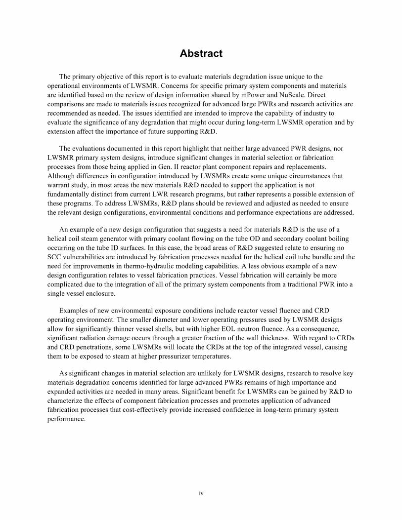
Abstract
The primary objective of this report is to evaluate materials degradation issue unique to the operational environments of LWSMR. Concerns for specific primary system components and materials are identified based on the review of design information shared by mPower and NuScale. Direct comparisons are made to materials issues recognized for advanced large PWRs and research activities are recommended as needed. The issues identified are intended to improve the capability of industry to evaluate the significance of any degradation that might occur during long-term LWSMR operation and by extension affect the importance of future supporting R&D.
The evaluations documented in this report highlight that neither large advanced PWR designs, nor LWSMR primary system designs, introduce significant changes in material selection or fabrication processes from those being applied in Gen. II reactor plant component repairs and replacements. Although differences in configuration introduced by LWSMRs create some unique circumstances that warrant study, in most areas the new materials R&D needed to support the application is not fundamentally distinct from current LWR research programs, but rather represents a possible extension of these programs. To address LWSMRs, R&D plans should be reviewed and adjusted as needed to ensure the relevant design configurations, environmental conditions and performance expectations are addressed.
An example of a new design configuration that suggests a need for materials R&D is the use of a helical coil steam generator with primary coolant flowing on the tube OD and secondary coolant boiling occurring on the tube ID surfaces. In this case, the broad areas of R&D suggested relate to ensuring no SCC vulnerabilities are introduced by fabrication processes needed for the helical coil tube bundle and the need for improvements in thermo-hydraulic modeling capabilities. A less obvious example of a new design configuration relates to vessel fabrication practices. Vessel fabrication will certainly be more complicated due to the integration of all of the primary system components from a traditional PWR into a single vessel enclosure.
Examples of new environmental exposure conditions include reactor vessel fluence and CRD operating environment. The smaller diameter and lower operating pressures used by LWSMR designs allow for significantly thinner vessel shells, but with higher EOL neutron fluence. As a consequence, significant radiation damage occurs through a greater fraction of the wall thickness. With regard to CRDs and CRD penetrations, some LWSMRs will locate the CRDs at the top of the integrated vessel, causing them to be exposed to steam at higher pressurizer temperatures.
As significant changes in material selection are unlikely for LWSMR designs, research to resolve key materials degradation concerns identified for large advanced PWRs remains of high importance and expanded activities are needed in many areas. Significant benefit for LWSMRs can be gained by R&D to characterize the effects of component fabrication processes and promotes application of advanced fabrication processes that cost-effectively provide increased confidence in long-term primary system performance.

v
Acknowledgments
This report would not have been possible without the generous assistance provided by SMR vendors, mPower and NuScale. The authors appreciate the interactions with mPower and NuScale staff helping clarify individual SMR design aspects and enabling the assessment of potential materials issues.
vi
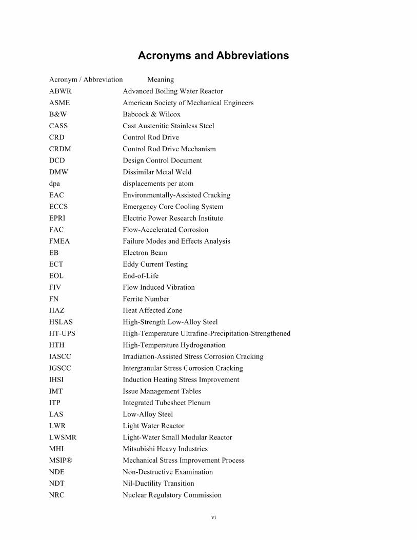
Acronyms and Abbreviations
Acronym / Abbreviation Meaning ABWR Advanced Boiling Water Reactor ASME American Society of Mechanical Engineers B&W Babcock & Wilcox CASS Cast Austenitic Stainless Steel CRD Control Rod Drive CRDM Control Rod Drive Mechanism DCD Design Control Document DMW Dissimilar Metal Weld dpa displacements per atom EAC Environmentally-Assisted Cracking ECCS Emergency Core Cooling System EPRI Electric Power Research Institute FAC Flow-Accelerated Corrosion FMEA Failure Modes and Effects Analysis EB Electron Beam ECT Eddy Current Testing EOL End-of-Life FIV Flow Induced Vibration FN Ferrite Number HAZ Heat Affected Zone HSLAS High-Strength Low-Alloy Steel HT-UPS High-Temperature Ultrafine-Precipitation-Strengthened HTH High-Temperature Hydrogenation IASCC Irradiation-Assisted Stress Corrosion Cracking IGSCC Intergranular Stress Corrosion Cracking IHSI Induction Heating Stress Improvement IMT Issue Management Tables ITP Integrated Tubesheet Plenum LAS Low-Alloy Steel LWR Light Water Reactor LWSMR Light-Water Small Modular Reactor MHI Mitsubishi Heavy Industries MSIP® Mechanical Stress Improvement Process NDE Non-Destructive Examination NDT Nil-Ductility Transition NRC Nuclear Regulatory Commission
vii
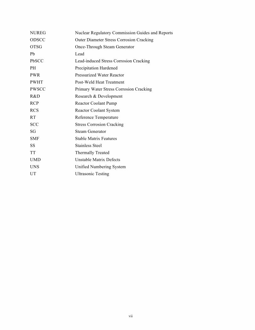
NUREG Nuclear Regulatory Commission Guides and Reports ODSCC Outer Diameter Stress Corrosion Cracking OTSG Once-Through Steam Generator Pb Lead PbSCC Lead-induced Stress Corrosion Cracking PH Precipitation Hardened PWR Pressurized Water Reactor PWHT Post-Weld Heat Treatment PWSCC Primary Water Stress Corrosion Cracking R&D Research & Development RCP Reactor Coolant Pump RCS Reactor Coolant System RT Reference Temperature SCC Stress Corrosion Cracking SG Steam Generator SMF Stable Matrix Features SS Stainless Steel TT Thermally Treated UMD Unstable Matrix Defects UNS Unified Numbering System UT Ultrasonic Testing
viii
Definitions
The following set of definitions is provided to clarify terminology used within this report. This listing is not intended to be a comprehensive glossary of technical terms, but rather a key listing of terms helpful to a knowledgeable reader.
Advanced PWRs (or large advanced PWRs)
Refers to the set of advanced PWR designs currently being evaluated for commercial deployment in the U.S. Includes the Westinghouse AP1000, AREVA U.S. EPR™, and Mitsubishi Heavy Industries (MHI) APWR designs.
Alloy 52, Alloy 152, and Alloy 52M
Common designations used by industry for UNS N06052 (SFA- 5.14, ERNiCrFe-7), UNS W86152 (SFA 5.11, ENiCrFe-7), or UNS N06054 (SFA-5.14, ERNiCrFe-7A), respectively.
Alloy 625 Common designation used by industry for a Nickel-Chromium alloy with additions of Niobium (Columbium) and Molybdenum identified by UNS N06625.
Alloy 690 Common designation used by industry for the Ni-Cr-Fe alloy identified by UNS N06690.
Alloy A-286 Common designation used by industry for the precipitation-hardenable, austenitic Fe-Ni-Cr alloy identified by UNS S66286.
Alloy X-750 Common designation used by industry for a Ni-Cr alloy made precipitation-hardenable by additions of Aluminum and Titanium. Alloy X-750 is identified by designation UNS N07750.
Alloy D9
Modified type 316 stainless steel with controlled additions of titanium and silicon. It has also reduced chromium content and increased nickel content. Its swelling resistance to neutron irradiation, and irradiation creep behavior are better than those of type 316 stainless steel.
Beltline
Region of the reactor vessel (shell material including welds, heat affected zones, and plates or forgings) as defined in 10 CFR 50.61(a)(3), that directly surrounds the effective height of the active core and adjacent regions of the reactor vessel that are predicted to experience sufficient neutron radiation damage to be considered in the selection for the most limiting material with regard to radiation damage.
Fluence Time-integrated neutron flux. Neutron flux is the number of neutrons passing through a unit area per unit time. Neutron fluence is typically expressed as neutrons/cm2.
Forging Plastically deforming metal, usually hot, into a desired shape by means of localized compressive forces exerted by presses, special forging machines, or by manual or power hammers.
Gen. II Refers to designs associated with operating reactors in the U.S. Gen. II may be used interchangeably with “operating plant”.
Gen. III Indicates advanced reactor designs having active safety systems. Gen. III PWR designs being evaluated for commercial deployment in the U.S include the AREVA U.S.EPR™ and APWR designs.
Gen. III+ Indicates advanced reactor designs having passive safety systems. The Westinghouse AP1000 is the only large Gen. III+ PWR design being considered for commercial deployment in the U.S.
High-Temperature Creep-resistant wrought stainless steel originally developed by the DOE
ix
Ultrafine-Precipitation-Strengthened (HT-UPS) stainless steel
advanced reactor materials program current being considered for application to LWRs.
Light Water Small Modular Reactor (LWSMR)
Refers to reactor designs having capacities less than 350 MWe. Although the B&W mPower and NuScale LWSMR designs also fit into the Gen III+ reactor design category, in the context of this report, Gen. III or Gen. III+ is used in the context of large plant designs and the LWSMR is used to broadly describe small reactors that are derived from light-water PWR technologies.1
Nickel-Base Alloy
Refers to alloys whose primary constituent is nickel. Examples include Alloy 600, 690, and X-750. In some cases, space constraints result in the use of the term Ni-Alloy instead of nickel-base alloy. The terms are used interchangeably within this report.
Nozzles
Defined to include full penetration welded vessel penetrations, sometimes with thermal sleeves or other features. The IMTs distinguish between full penetration welded nozzles and other vessel penetrations using partial penetration welds. See “penetrations” below. Examples of nozzles include reactor vessel inlet and outlet nozzles, pressurizer surge and safety nozzles, and steam generator channel head primary inlet and outlet nozzles.
Piping Components General term used to describe pipe segments and fittings, branch connections, welded attachments, thermowell bosses and thermowells.
Tcold Refers to the core inlet temperature. Thot Refers to the core outlet temperature. TPZR Refers to the pressurizer operating temperature.
Type 17-4PH Precipitation-hardenable martensitic stainless steel with Cu and Nb⁄Cb additions (17Cr-4Ni-3Cu) identified by UNS S17400.
Type XM-19 Nitrogen strengthened austenitic stainless steel that has approximately twice the yield strength of 300 series stainless steels. XM-19 is identified by the designation UNS S20910.
Welded Attachment Refers to components that are welded to the interior or exterior surfaces of primary pressure-retaining components.
1 Note: sometimes referred to as iPWRs
x
Contents
Abstract ................................................................................................................................................. iv Acknowledgments ................................................................................................................................. v Acronyms and Abbreviations ................................................................................................................ vi 1.0 Introduction ................................................................................................................................... 1-1 2.0 Approach ....................................................................................................................................... 2-1
2.1 Scope of Components Evaluated .......................................................................................... 2-1 2.2 Use of Failures Modes and Effect Analysis (FMEA) .......................................................... 2-1
3.0 Evaluation of Large Advanced PWRs .......................................................................................... 3-1 3.1 Component Descriptions and General Discussion ............................................................... 3-1
3.1.1 Primary System Pressure Retaining Components ..................................................... 3-1 3.1.2 Reactor Internals ........................................................................................................ 3-6 3.1.3 Control Rod Drives (Housings & Drive Mechanisms) ............................................. 3-13 3.1.4 Steam Generators ...................................................................................................... 3-15
3.2 FMEA Summary .................................................................................................................. 3-19 4.0 Evaluation of B&W mPowerTM Reactor .................................................................................... 4-1
4.1 Component Descriptions and General Discussion ............................................................... 4-1 4.1.1 mPower Primary System Pressure Boundary Components ...................................... 4-3 4.1.2 Reactor Internals ........................................................................................................ 4-5 4.1.3 Control Rod Drive Mechanisms ................................................................................ 4-9 4.1.4 Steam Generator ........................................................................................................ 4-10 4.1.5 Reactor Coolant Pumps ............................................................................................. 4-12
4.2 FMEA Comparison to Large Advanced PWRs ................................................................... 4-13 5.0 Evaluation of NuScale Reactor ..................................................................................................... 5-17
5.1 Component Descriptions and General Discussion ............................................................... 5-17 5.1.1 Primary System Pressure-Retaining Components ..................................................... 5-20 5.1.2 Reactor Internals ........................................................................................................ 5-24 5.1.3 Control Rod Drives ................................................................................................... 5-26 5.1.4 Steam Generator ........................................................................................................ 5-26 5.1.5 Containment Vessel ................................................................................................... 5-29
5.2 FMEA Comparison to Large Advanced PWRs ................................................................... 5-29 6.0 Materials R&D Gap Assessment Results ..................................................................................... 6-1
6.1 Large Advanced PWR Baseline Materials R&D Needs ...................................................... 6-1 6.1.1 Performance of High Chromium, Nickel-Base Alloys 690, 52 and 152 ................... 6-1 6.1.2 Reactor Vessel Integrity ............................................................................................ 6-2 6.1.3 Residual Stress Evaluation - SCC Mitigation Capabilities & Guidance ................... 6-2 6.1.4 Environmental Effects on Fatigue Resistance ........................................................... 6-3
xi
6.1.5 Effects of Material Composition and Fabrication Processes on Irradiation-Induced Degradation ............................................................................................................... 6-4
6.1.6 Steam Generator Long-Term Performance ............................................................... 6-5 6.2 LWSMR Design Comparison .............................................................................................. 6-5 6.3 LWSMR Materials R&D Needs .......................................................................................... 6-9
6.3.1 Performance of Alloy 690 and its Weld Metals ........................................................ 6-9 6.3.2 Reactor Vessel Embrittlement ................................................................................... 6-9 6.3.3 Assessment of Environmental Fatigue Effects .......................................................... 6-10 6.3.4 Highly Irradiated Materials Performance Data ......................................................... 6-10 6.3.5 Steam Generator Design ............................................................................................ 6-10 6.3.6 Flow-Induced Vibration Evaluation .......................................................................... 6-12
7.0 Conclusions ................................................................................................................................... 7-1 7.1 Large Advanced PWRs ........................................................................................................ 7-1 7.2 LWSMRs .............................................................................................................................. 7-2 7.3 Summary .............................................................................................................................. 7-3
8.0 References ..................................................................................................................................... 8-1 9.0 APPENDIX A: ADVANCED PWR MATERIALS LISTS ......................................................... 9.1
xii
Figures
Figure 2-1 Overview of FMEA Elements ............................................................................................. 2-2 Figure 3-1 Typical Advanced PWR Reactor Pressure Vessel .............................................................. 3-2 Figure 3-2 Example of the CE Design Welded Shroud. ....................................................................... 3-8 Figure 3-3 Illustration of Welded Shroud Construction ....................................................................... 3-8 Figure 3-4 Heavy Reflector and Core Barrel Assembly ....................................................................... 3-9 Figure 3-5 Lower Internals Illustration ................................................................................................. 3-11 Figure 3-6 Illustration of Advanced PWR Reactor Internals High Strength Fastener / Hardware
Applications .................................................................................................................................. 3-13 Figure 3-7 AP1000 CRDM ................................................................................................................... 3-16 Figure 3-8 U.S. EPR CRDM ................................................................................................................. 3-16 Figure 3-9 AP1000 Steam Generator .................................................................................................... 3-18 Figure 4-1 B&W mPower Reactor Cutaway ........................................................................................ 4-2 Figure 4-2 B&W mPower Pressure-Retaining Components ................................................................ 4-4 Figure 4-3 mPower Internals Illustration .............................................................................................. 4-8 Figure 4-4 mPower Steam Generator Details ....................................................................................... 4-12 Figure 5-1 NuScale Reactor System Major Components ..................................................................... 5-19 Figure 5-2 NuScale Section Drawing with Pressure Boundary Components Annotated ..................... 5-20 Figure 5-3 Helical Coil Heat Exchanger Example ................................................................................ 5-27
xiii
Tables
Table 3-1 FMEA Conclusions for Large Advanced PWR Pressure Boundary Components ............... 3-20 Table 3-2 FMEA Conclusions for Advanced PWR Reactor Internals ................................................. 3-20 Table 3-3 FMEA Conclusions for Advanced PWR Control Rod Drives ............................................. 3-21 Table 3-4 FMEA Conclusions for Advanced PWR Steam Generators ................................................ 3-21 Table 4-1 FMEA Comparison for mPower Reactor Vessel Shells, Heads, Nozzles, & Welds ........... 4-14 Table 4-2 FMEA Comparison for mPower PWR Reactor Internals .................................................... 4-15 Table 4-3 FMEA Comparison for mPower Control Rod Drives .......................................................... 4-15 Table 4-4 FMEA Comparison for mPower Steam Generator ............................................................... 4-16 Table 5-1 FMEA Comparison for NuScale Primary System Pressure Boundary Components ........... 5-30 Table 5-2 FMEA Comparison for NuScale Reactor Internals .............................................................. 5-30 Table 5-3 FMEA Comparison for NuScale Steam Generator .............................................................. 5-32 Table 5-4 FMEA Comparison for NuScale Containment Vessel ......................................................... 5-32 Table 6-1 Design Comparison – Material Selection / Environmental Conditions ............................... 6-6 Table 6-2 Design Comparison – Primary System Characteristics ........................................................ 6-8 Table A-1 Primary Pressure Retaining Materials ................................................................................. 9.1 Table A-2 Reactor Vessel Internals Materials ...................................................................................... 9.2 Table A-3 Control Rod Drive Materials (Housings and Drive Mechanisms) ...................................... 9.3 Table A-4 Steam Generator Materials .................................................................................................. 9.4
1-1
1.0 Introduction
Years of materials research have resulted in an expanding knowledge base regarding the materials performance issues associated with light water reactor (LWR) designs. In particular, materials research and development (R&D) conducted over the last two decades has been focused on managing degradation issues and resolving materials vulnerabilities for Generation II reactor designs.2
Since the late 1990s a number of advanced Generation III and III+ LWR designs have been developed, and these designs (e.g., Westinghouse AP1000) are now being constructed in the U.S. In most cases, the significant materials performance vulnerabilities found to exist for 2nd generation reactor designs (and that are a focus of ongoing materials R&D programs) are simply not relevant to advanced reactors. Examples include irradiation-assisted stress corrosion cracking (IASCC) of baffle bolts (addressed by design modifications that replace bolted core former assemblies with either welded or stacked ring core former assemblies) and primary water stress corrosion cracking (PWSCC) susceptibility (largely addressed through replacement of Alloys 600, 82 and 182 with Alloys 690, 52 and 152). However, in other cases, new R&D needs may be suggested by the introduction of new materials or as a result of changes in component service environment. Examples include substantial increases in end of life (EOL) neutron fluence for many near core components and replacement of cast stainless steel piping components with large stainless steel forgings. In the first case, development of additional high fluence materials property data, including characterization of void swelling, has become a relevant materials research need. In the second case, replacement of cast materials for the purpose of improved inspectability suggests a need to ensure no new vulnerabilities are introduced by the use of large stainless steel forgings.
More recently, small modular reactor (SMR) designs have been proposed as a means to address some of the barriers to deployment of large reactors (e.g., water resource limitations and high capital costs). In the context of light water SMR (LWSMR3) primary systems material selection and application, LWSMR technologies represent a further refinement of large Gen III and Gen. III+ PWRs, with relatively few changes to materials selection or materials processing and fabrication practices anticipated.
As a result, evaluation of more mature advanced PWR designs represents a useful starting point for evaluation of LWSMR designs. This approach is a reasonable method to address the lack of public LWSMR design details since it is known that component design, material selection/processing and fabrication approaches used for larger advanced PWR designs are very likely to be adapted for LWSMR designs and a significant amount of public information available for advanced PWR designs as a result of U.S. NRC licensing submittals.
With specific regard to materials R&D, recent efforts have been largely focused on operating Gen. II reactor designs and specifically on the fixed set of materials and design configurations applicable to Gen. II reactors. For advanced LWRs (both large advanced PWRs and LWSMRs), opportunities exist to study material variants or variations in fabrication practices, both of which can benefit long-term performance. Additionally, changes in design may also affect the degradation phenomena representing the most significant challenges to component integrity or serviceability. For example, changes to core design may cause void swelling to replace IASCC as the primary degradation concern for near-core reactor internals. A more subtle example is a shift in vessel embrittlement mechanism. In contrast with Gen. II beltline materials, the most
2 Refers to the class of commercial reactors built up to the end of the 1990s. 3 Note: LWSMRs are sometimes referred to as iPWRs
1-2
significant embrittlement effects in advanced reactors may be late occurring embrittlement phenomena, since embrittlement due to Cu or Ni precipitates has been addressed by improved material controls. Finally, even for cases where material selection and fabrication processes are not changed substantially, variations in component configuration or service environment may suggest additional R&D needs.
Materials R&D issues are identified through a systematic review of both large advanced PWR and selected LWSMR designs (mPower and NuScale) where information regarding the primary system design approach could be obtained. Agreements to share information were established with mPower and NuScale, but could not be set up with other LWSMR vendors. The resulting materials R&D needs identified are drawn not only from the perspective of long-term vulnerabilities, but also address uncertainties associated with materials processing and fabrication and with new component configurations and service environments.
2-1
2.0 Approach
Using lessons learned from the operating PWR fleet as described in the Introduction, many of the common materials degradation concerns associated with operating reactors have been mitigated. As a result, when compared to equivalent components in operating PWRs, the safety, economic, and operational risks associated with materials degradation for advanced PWRs (and similarly LWSMRs) are generally low for all primary system components. However, these designs are not immune to materials degradation, especially over an extended service life (designs are for a minimum of 60 years) or where substantial changes exist in component configuration or service environment.
2.1 Scope of Components Evaluated
In general, the scope of systems and components evaluated is limited to the nuclear steam supply system (NSSS). The primary system scope includes the core support internals, control rod drives and supporting internals, the reactor vessel, primary system pumps and piping components, the pressurizer, and interfacing system connections out to an isolating valve. Secondary system components include only the steam generators, specifically including heat transfer tubes, tube supports, and the secondary-side shell (with the boundary drawn at the feedwater inlet and main steam outlet nozzles). Although variations in primary system configuration introduce some differences, the overall functionality of the components evaluated is similar for all designs. As a part of describing each reactor design in Sections 3, 4 and 5, specific discussion is included for the scope of components evaluated.
The notable addition to the typical scope evaluated is the NuScale containment vessel in Section 5. This component was added to the scope of evaluation for the NuScale design because of the nontraditional function of the containment vessel.
2.2 Use of Failures Modes and Effect Analysis (FMEA)
In assessing the primary system components, Failure Modes and Effect Analysis (FMEA) represents a useful framework to identify potential material performance concerns. The general approach is given in Figure 2-1 and illustrates how primary system component degradation concerns can be prioritized according to how serious their consequences are (step 2), how frequently they might occur (step 3), and how easily they can be detected by in-service inspection (step 4).
In the context of advanced PWR and LWSMR primary system components, each of the three FMEA evaluation elements is recognized to be low in comparison with operating Gen. II PWRs. As a result, a relative approach is applied, such that assessments are based on relative comparison with other primary system components within the same design. The following general guidelines can be applied for evaluating each of the elements of FMEA: probability (occurrence), severity, and detection.

2-2
Figure 2-1 Overview of FMEA Elements
(Source: Wikipedia)
The occurrence element is evaluated in the context of confidence in continued system integrity, such that inspection programs need not be extensive and are primarily confirmatory in nature. There should be high confidence that the primary system components will provide long-term, problem free service and will retain adequate margins against degradation that leads to loss of component function under all anticipated service conditions. Where uncertainties exist regarding the capabilities of the primary system components to meet the criteria, R&D needs are suggested.
Evaluation of the severity element includes consideration of not only safety consequences, but also economic consequences and the potential for increased regulatory scrutiny. Where the consequences of component degradation are greater, increased confidence in resistance to degradation or in component structural margin against failure is warranted.
Evaluation of the detection element focuses on the capability to detect degradation prior to a significant impact on component function. Where detection capabilities are limited or in-service inspection is unlikely to be performed, increased confidence in resistance to degradation or in component structural margin against failure is warranted.
Although the focus of this project is to identify research that will improve the capability of industry to evaluate step 3 (probability of occurrence), the other two elements of FMEA, severity (consequence of failure) and detection (probability of detection by NDE) are also discussed, as they affect the significance of any degradation that might occur and by extension affect the importance of supporting R&D.
Sections 3, 4 and 5 in this report summarize evaluations of large advanced PWRs, the B&W mPower LWSMR design and the NuScale LWSMR design. Each of these sections describes the primary system configuration, materials of construction, and any details known regarding materials processing and fabrication controls. It is important to note that certain aspects are considered proprietary and/or still evolving for the LWSMR designs. Although some of these aspects were shared by vendors during the review process, they are not included in the evaluation. Using the available information, a summary level FMEA is performed. Section 6 contains the resulting set of materials R&D needs suggested by the evaluations.
3-1
3.0 Evaluation of Large Advanced PWRs
3.1 Component Descriptions and General Discussion
The scope of large advanced PWR components evaluated includes the reactor vessel, reactor internals, pressurizer, reactor coolant pump casings, steam generators and ASME Class 1 piping components. Several designs have been collectively considered in this evaluation.4 Since the intent of this Section 3 evaluation is to leverage data associated with more mature large advanced PWR designs as a starting point for evaluation of LWSMRs, the assessment focuses on components with more direct applicability to LWSMRs. Although some assessment of piping systems is included, large diameter piping components are not a primary focus of the assessment. This is appropriate given that the current design approach for LWSMRs is to consolidate the reactor vessel, pressurizer and steam generator functions into a single “integrated” vessel with relatively little external piping.
Design, materials selection, fabrication approaches and primary system environmental conditions are based on review of the current revisions of Design Control Documents (DCDs) for advanced PWRs.
3.1.1 Primary System Pressure Retaining Components
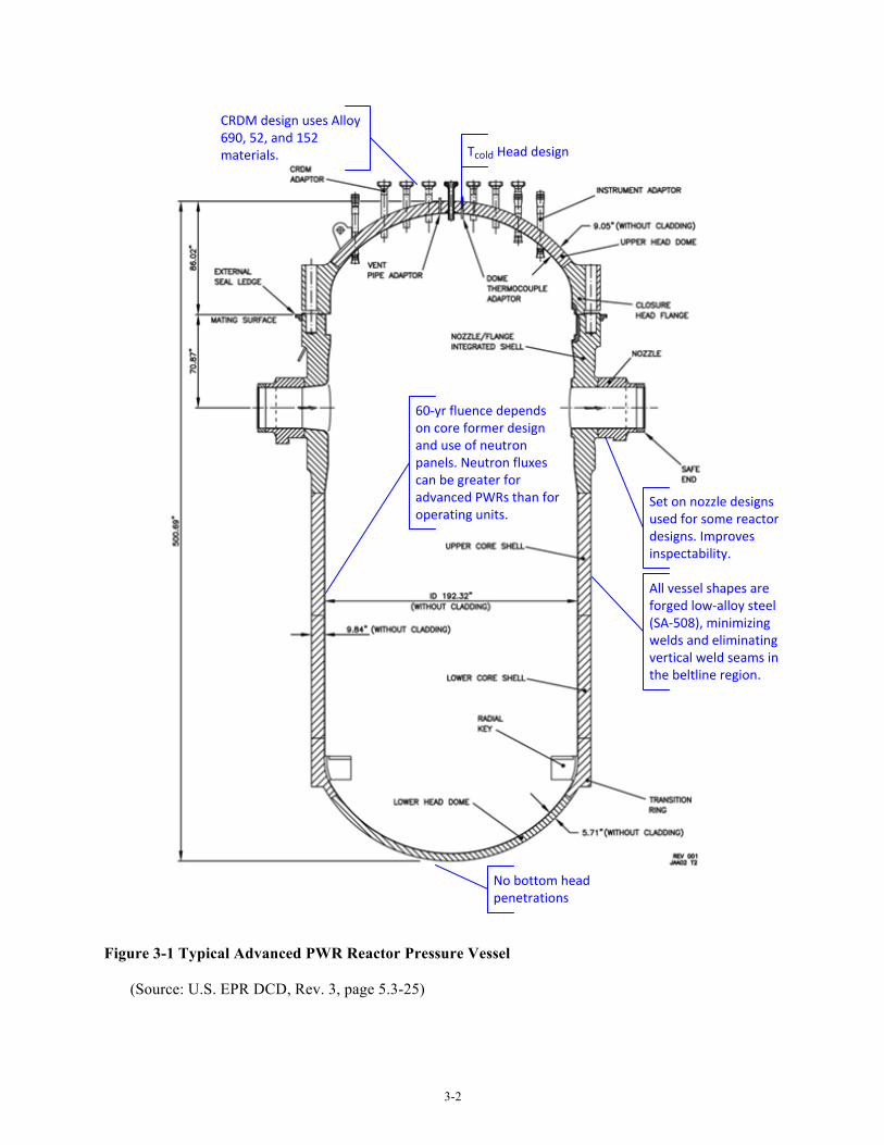
Given the objective of leveraging conclusions based on advanced PWR designs for LWSMRs, the focus of the primary system pressure boundary evaluation is the reactor vessel. An example advanced PWR reactor vessel with key design features annotated is shown in Figure 3-1. Key features of advanced PWR vessel designs include:
• Elimination of vertical seam welds through use of full circumference ring forgings rather than rolled plate sections,
• Elimination of reactor vessel penetrations and nozzles from the lower vessel head (instrumentation is routed through the upper head),
• Replacement of lower Cr, Alloy 600, 82 and 182 nickel-base materials with higher Cr, Alloy 690, 52, and 152 materials,
• Tcold vessel head design, where some cold leg flow is routed to the vessel upper head plenum so that upper head penetrations are subject to lower service temperatures.
4 Advanced PWR designs considered in the evaluation include designs for which Design Control Documents have been submitted to NRC such that significant public information on the design is available. These include the Westinghouse AP1000, AREVA U.S. EPR, and Mitsubishi APWR designs.
3-2
Set on nozzle designs used for some reactor designs. Improves inspectability.
All vessel shapes are forged low-‐alloy steel (SA-‐508), minimizing welds and eliminating vertical weld seams in the beltline region.
60-‐yr fluence depends on core former design and use of neutron panels. Neutron fluxes can be greater for advanced PWRs than for operating units.
No bottom head penetrations
Tcold Head design
CRDM design uses Alloy 690, 52, and 152 materials.
Figure 3-1 Typical Advanced PWR Reactor Pressure Vessel
(Source: U.S. EPR DCD, Rev. 3, page 5.3-25)
3-3
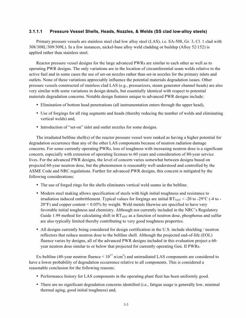
3.1.1.1 Pressure Vessel Shells, Heads, Nozzles, & Welds (SS clad low-alloy steels)
Primary pressure vessels are stainless steel clad low alloy steel (LAS), i.e. SA-508, Gr. 3, Cl. 1 clad with 308/308L/309/309L). In a few instances, nickel-base alloy weld cladding or buildup (Alloy 52/152) is applied rather than stainless steel.
Reactor pressure vessel designs for the large advanced PWRs are similar to each other as well as to operating PWR designs. The only variations are in the location of circumferential seam welds relative to the active fuel and in some cases the use of set-on nozzles rather than set-in nozzles for the primary inlets and outlets. None of these variations appreciably influence the potential materials degradation issues. Other pressure vessels constructed of stainless clad LAS (e.g., pressurizers, steam generator channel heads) are also very similar with some variations in design details, but essentially identical with respect to potential materials degradation concerns. Notable design features unique to advanced PWR designs include:
• Elimination of bottom head penetrations (all instrumentation enters through the upper head),
• Use of forgings for all ring segments and heads (thereby reducing the number of welds and eliminating vertical welds) and,
• Introduction of “set-on” inlet and outlet nozzles for some designs.
The irradiated beltline shell(s) of the reactor pressure vessel were ranked as having a higher potential for degradation occurrence than any of the other LAS components because of neutron radiation damage concerns. For some currently operating PWRs, loss of toughness with increasing neutron dose is a significant concern, especially with extension of operating licenses to 60 years and consideration of 80-year service lives. For the advanced PWR designs, the level of concern varies somewhat between designs based on projected 60-year neutron dose, but the phenomenon is reasonably well understood and controlled by the ASME Code and NRC regulations. Further for advanced PWR designs, this concern is mitigated by the following considerations:
• The use of forged rings for the shells eliminates vertical weld seams in the beltline.
• Modern steel making allows specification of steels with high initial toughness and resistance to irradiation induced embrittlement. Typical values for forgings are initial RTNDT < -20 to -29°C (-4 to -20°F) and copper content < 0.05% by weight. Weld metals likewise are specified to have very favorable initial toughness and chemistry. Although not currently included in the NRC’s Regulatory Guide 1.99 method for calculating shift in RTNDT as a function of neutron dose, phosphorus and sulfur are also typically limited thereby contributing to very good toughness properties.
• All designs currently being considered for design certification in the U.S. include shielding / neutron reflectors that reduce neutron dose to the beltline shell. Although the projected end-of-life (EOL) fluence varies by designs, all of the advanced PWR designs included in this evaluation project a 60-year neutron dose similar to or below that projected for currently operating Gen. II PWRs.
Ex-beltline (40-year neutron fluence < 1017 n/cm2) and unirradiated LAS components are considered to have a lower probability of degradation occurrence relative to all components. This is considered a reasonable conclusion for the following reasons:
• Performance history for LAS components in the operating plant fleet has been uniformly good.
• There are no significant degradation concerns identified (i.e., fatigue usage is generally low, minimal thermal aging, good initial toughness) and,
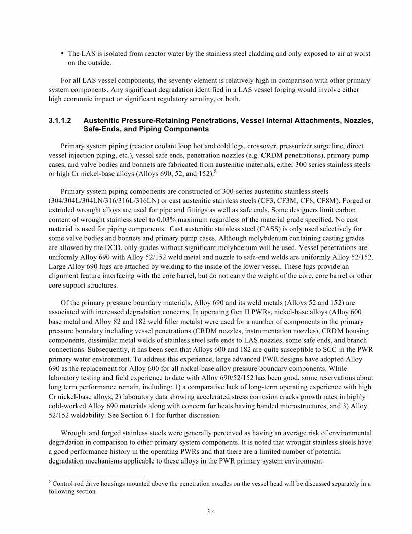
3-4
• The LAS is isolated from reactor water by the stainless steel cladding and only exposed to air at worst on the outside.
For all LAS vessel components, the severity element is relatively high in comparison with other primary system components. Any significant degradation identified in a LAS vessel forging would involve either high economic impact or significant regulatory scrutiny, or both.
3.1.1.2 Austenitic Pressure-Retaining Penetrations, Vessel Internal Attachments, Nozzles, Safe-Ends, and Piping Components
Primary system piping (reactor coolant loop hot and cold legs, crossover, pressurizer surge line, direct vessel injection piping, etc.), vessel safe ends, penetration nozzles (e.g. CRDM penetrations), primary pump cases, and valve bodies and bonnets are fabricated from austenitic materials, either 300 series stainless steels or high Cr nickel-base alloys (Alloys 690, 52, and 152).5
Primary system piping components are constructed of 300-series austenitic stainless steels (304/304L/304LN/316/316L/316LN) or cast austenitic stainless steels (CF3, CF3M, CF8, CF8M). Forged or extruded wrought alloys are used for pipe and fittings as well as safe ends. Some designers limit carbon content of wrought stainless steel to 0.03% maximum regardless of the material grade specified. No cast material is used for piping components. Cast austenitic stainless steel (CASS) is only used selectively for some valve bodies and bonnets and primary pump cases. Although molybdenum containing casting grades are allowed by the DCD, only grades without significant molybdenum will be used. Vessel penetrations are uniformly Alloy 690 with Alloy 52/152 weld metal and nozzle to safe-end welds are uniformly Alloy 52/152. Large Alloy 690 lugs are attached by welding to the inside of the lower vessel. These lugs provide an alignment feature interfacing with the core barrel, but do not carry the weight of the core, core barrel or other core support structures.
Of the primary pressure boundary materials, Alloy 690 and its weld metals (Alloys 52 and 152) are associated with increased degradation concerns. In operating Gen II PWRs, nickel-base alloys (Alloy 600 base metal and Alloy 82 and 182 weld filler metals) were used for a number of components in the primary pressure boundary including vessel penetrations (CRDM nozzles, instrumentation nozzles), CRDM housing components, dissimilar metal welds of stainless steel safe ends to LAS nozzles, some safe ends, and branch connections. Subsequently, it has been seen that Alloys 600 and 182 are quite susceptible to SCC in the PWR primary water environment. To address this experience, large advanced PWR designs have adopted Alloy 690 as the replacement for Alloy 600 for all nickel-base alloy pressure boundary components. While laboratory testing and field experience to date with Alloy 690/52/152 has been good, some reservations about long term performance remain, including: 1) a comparative lack of long-term operating experience with high Cr nickel-base alloys, 2) laboratory data showing accelerated stress corrosion cracks growth rates in highly cold-worked Alloy 690 materials along with concern for heats having banded microstructures, and 3) Alloy 52/152 weldability. See Section 6.1 for further discussion.
Wrought and forged stainless steels were generally perceived as having an average risk of environmental degradation in comparison to other primary system components. It is noted that wrought stainless steels have a good performance history in the operating PWRs and that there are a limited number of potential degradation mechanisms applicable to these alloys in the PWR primary system environment.
5 Control rod drive housings mounted above the penetration nozzles on the vessel head will be discussed separately in a following section.
3-5
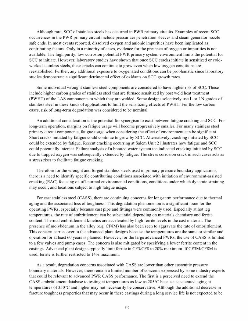
Although rare, SCC of stainless steels has occurred in PWR primary circuits. Examples of recent SCC occurrences in the PWR primary circuit include pressurizer penetration sleeves and steam generator nozzle safe ends. In most events reported, dissolved oxygen and anionic impurities have been implicated as contributing factors. Only in a minority of cases, evidence for the presence of oxygen or impurities is not available. The high purity, low corrosion potential PWR primary system environment limits the potential for SCC to initiate. However, laboratory studies have shown that once SCC cracks initiate in sensitized or cold-worked stainless steels, these cracks can continue to grow even when low oxygen conditions are reestablished. Further, any additional exposure to oxygenated conditions can be problematic since laboratory studies demonstrate a significant detrimental effect of oxidants on SCC growth rates.
Some individual wrought stainless steel components are considered to have higher risk of SCC. These include higher carbon grades of stainless steel that are furnace sensitized by post weld heat treatment (PWHT) of the LAS components to which they are welded. Some designs selectively use L or LN grades of stainless steel in these kinds of applications to limit the sensitizing effects of PWHT. For the low carbon cases, risk of long-term degradation was considered to be nominal.
An additional consideration is the potential for synergism to exist between fatigue cracking and SCC. For long-term operation, margins on fatigue usage will become progressively smaller. For many stainless steel primary circuit components, fatigue usage when considering the effect of environment can be significant. Short cracks initiated by fatigue could continue to grow by SCC. Alternatively, cracking initiated by SCC could be extended by fatigue. Recent cracking occurring at Salem Unit 2 illustrates how fatigue and SCC could potentially interact. Failure analysis of a borated water system tee indicated cracking initiated by SCC due to trapped oxygen was subsequently extended by fatigue. The stress corrosion crack in such cases acts as a stress riser to facilitate fatigue cracking.
Therefore for the wrought and forged stainless steels used in primary pressure boundary applications, there is a need to identify specific contributing conditions associated with initiation of environment-assisted cracking (EAC) focusing on off-normal environmental conditions, conditions under which dynamic straining may occur, and locations subject to high fatigue usage.
For cast stainless steel (CASS), there are continuing concerns for long-term performance due to thermal aging and the associated loss of toughness. This degradation phenomenon is a significant issue for the operating PWRs, especially because cast pipe and fittings were commonly used. Especially at hot leg temperatures, the rate of embrittlement can be substantial depending on materials chemistry and ferrite content. Thermal embrittlement kinetics are accelerated by high ferrite levels in the cast material. The presence of molybdenum in the alloy (e.g. CF8M) has also been seen to aggravate the rate of embrittlement. This concern carries over to the advanced plant designs because the temperatures are the same or similar and operation for at least 60 years is planned. However, for the large advanced PWRs, the use of CASS is limited to a few valves and pump cases. The concern is also mitigated by specifying a lower ferrite content in the castings. Advanced plant designs typically limit ferrite in CF3/CF8 to 20% maximum. If CF3M/CF8M is used, ferrite is further restricted to 14% maximum.
As a result, degradation concerns associated with CASS are lower than other austenitic pressure boundary materials. However, there remain a limited number of concerns expressed by some industry experts that could be relevant to advanced PWR CASS performance. The first is a perceived need to extend the CASS embrittlement database to testing at temperatures as low as 285°C because accelerated aging at temperatures of 350°C and higher may not necessarily be conservative. Although the additional decrease in fracture toughness properties that may occur in these castings during a long service life is not expected to be

3-6
a significant concern, there may be a need for additional data to demonstrate saturation in the degradation of properties through 80 years of operation. As a second consideration, because existing databases are skewed toward Mo containing CASS (CF8M) coupled with high ferrite fractions that suffer the greatest thermal aging embrittlement, there is a potential need to extend the database to include the less susceptible CASS materials that will be used in advanced PWR primary systems. It becomes progressively more difficult to demonstrate saturation of fracture toughness values for the less susceptible CASS materials.
3.1.1.3 Pressure-Retaining Bolting
High strength LAS (HSLAS) is widely used for flange closure bolting. Reactor vessel head closure bolting is commonly SA-540 Gr. B23 or B24, while for other flanged closures SA-193 Gr. B7 is often used. In these applications, the material is not exposed to reactor water during operation except in the event of flange or other leakage. Operating experience with these alloys has been generally quite good, but these alloys are subject to general corrosion, boric acid corrosion and, in the event of alternate wet and dry conditions, SCC. There is also a postulated thermal aging potential for long-term exposure (60+ years). Of these degradation mechanisms, boric acid corrosion from leakage is probably the biggest concern, but is largely addressed by boric acid management programs. Historically there have also been failures associated with contamination with aggressive species (e.g. molybdenum disulfide lubricant), but the known contaminants of concern are barred from use in the new plant systems. The SCC concern is mitigated in new plants by specifying a maximum hardness of 40 Rockwell C. Additionally, Regulatory Guide 1.65 limits the ultimate strength of reactor vessel closure studs to 170 ksi (1172 MPa) maximum as a further control on SCC susceptibility. In general, the overall risk of degradation of HSLAS bolting was considered to be a low probability in comparison with other primary system components. HSLAS (SA-193, Gr. B7 or B16) is also used for external bolting in the steam generator secondary shells for retaining various access hole covers. Because there is no potential for boric acid exposure, the risk of degradation to this bolting was generally considered to be somewhat lower than for primary system external bolting.
Some high-strength stainless steel alloys are also used for external bolting. These are primarily an austenitic precipitation hardened alloy, A-286 (SA-453, Gr. 660) and a martensitic precipitation hardened alloy, 17-4PH (SA-564, Type 630). These stainless steel alloys are resistant to general corrosion and boric acid corrosion. The main degradation concern for these alloys is SCC from periodic wetting in long-term operation. There is also some concern that long-term thermal aging may degrade SCC resistance. Although performance history for the stainless alloys has been generally good, the potential for SCC to occur in fasteners having higher hardness/strength or subject to thermal aging embrittlement causes the degradation risk to be somewhat greater than for the HSLAS fastener materials discussed above. Among high-strength stainless steel fasteners, Alloy A-286 was considered to be at a slightly greater risk of degradation than 17-4PH. Where 17-4PH is used in the new plant designs, it is specified to be in a heat treatment condition that is considered to be resistant to SCC (H1050, H1100, or H1150).
3.1.2 Reactor Internals
Materials performance improvements associated with advanced PWR reactor internals are primarily associated with design modifications rather than improved materials of construction or fabrication processes. This approach is reasonable since austenitic stainless steels have generally performed well in the operating Gen. II PWRs to date and the expectation is that they will do the same in the advanced plant designs. As will be detailed in the following discussion, the primary modification has been to eliminate the use of bolted core formers replacing these bolted designs with either welded core shrouds or stacked ring neutron reflectors.
3-7
However, there was some variation in the assessment of likelihood of degradation depending on component location, fabrication (welded vs. no welding), and level of neutron irradiation.
3.1.2.1 Structures & Welds
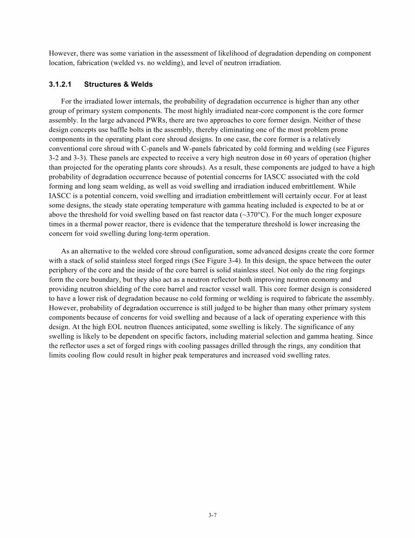
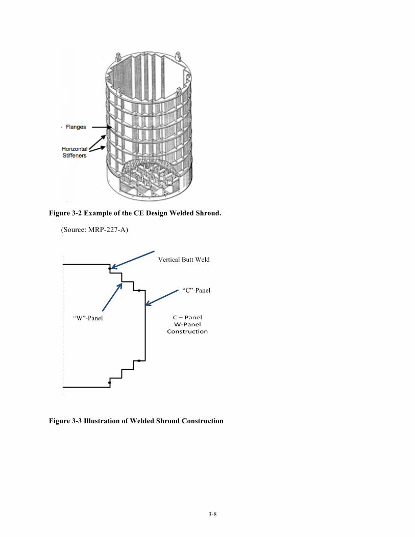
For the irradiated lower internals, the probability of degradation occurrence is higher than any other group of primary system components. The most highly irradiated near-core component is the core former assembly. In the large advanced PWRs, there are two approaches to core former design. Neither of these design concepts use baffle bolts in the assembly, thereby eliminating one of the most problem prone components in the operating plant core shroud designs. In one case, the core former is a relatively conventional core shroud with C-panels and W-panels fabricated by cold forming and welding (see Figures 3-2 and 3-3). These panels are expected to receive a very high neutron dose in 60 years of operation (higher than projected for the operating plants core shrouds). As a result, these components are judged to have a high probability of degradation occurrence because of potential concerns for IASCC associated with the cold forming and long seam welding, as well as void swelling and irradiation induced embrittlement. While IASCC is a potential concern, void swelling and irradiation embrittlement will certainly occur. For at least some designs, the steady state operating temperature with gamma heating included is expected to be at or above the threshold for void swelling based on fast reactor data (~370°C). For the much longer exposure times in a thermal power reactor, there is evidence that the temperature threshold is lower increasing the concern for void swelling during long-term operation.
As an alternative to the welded core shroud configuration, some advanced designs create the core former with a stack of solid stainless steel forged rings (See Figure 3-4). In this design, the space between the outer periphery of the core and the inside of the core barrel is solid stainless steel. Not only do the ring forgings form the core boundary, but they also act as a neutron reflector both improving neutron economy and providing neutron shielding of the core barrel and reactor vessel wall. This core former design is considered to have a lower risk of degradation because no cold forming or welding is required to fabricate the assembly. However, probability of degradation occurrence is still judged to be higher than many other primary system components because of concerns for void swelling and because of a lack of operating experience with this design. At the high EOL neutron fluences anticipated, some swelling is likely. The significance of any swelling is likely to be dependent on specific factors, including material selection and gamma heating. Since the reflector uses a set of forged rings with cooling passages drilled through the rings, any condition that limits cooling flow could result in higher peak temperatures and increased void swelling rates.
3-8
Figure 3-2 Example of the CE Design Welded Shroud.
(Source: MRP-227-A)
Figure 3-3 Illustration of Welded Shroud Construction
C – PanelW-‐Panel
Construction
“C”-Panel
“W”-Panel
Vertical Butt Weld
3-9
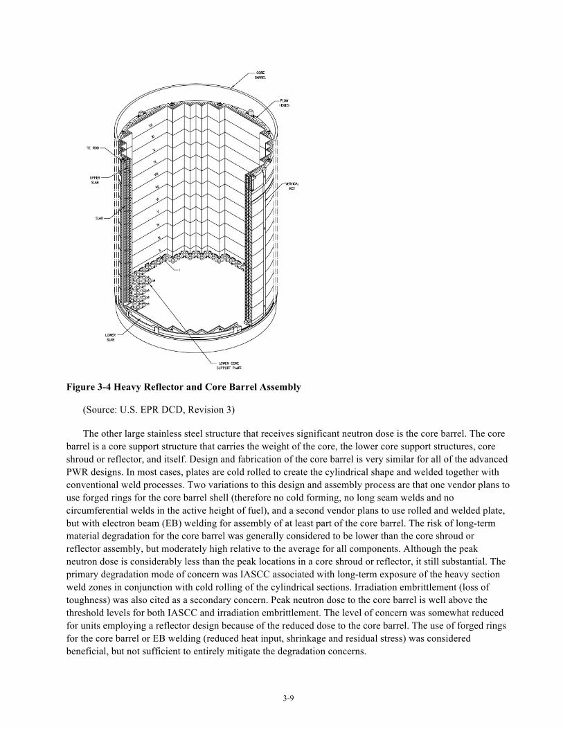
Figure 3-4 Heavy Reflector and Core Barrel Assembly
(Source: U.S. EPR DCD, Revision 3)
The other large stainless steel structure that receives significant neutron dose is the core barrel. The core barrel is a core support structure that carries the weight of the core, the lower core support structures, core shroud or reflector, and itself. Design and fabrication of the core barrel is very similar for all of the advanced PWR designs. In most cases, plates are cold rolled to create the cylindrical shape and welded together with conventional weld processes. Two variations to this design and assembly process are that one vendor plans to use forged rings for the core barrel shell (therefore no cold forming, no long seam welds and no circumferential welds in the active height of fuel), and a second vendor plans to use rolled and welded plate, but with electron beam (EB) welding for assembly of at least part of the core barrel. The risk of long-term material degradation for the core barrel was generally considered to be lower than the core shroud or reflector assembly, but moderately high relative to the average for all components. Although the peak neutron dose is considerably less than the peak locations in a core shroud or reflector, it still substantial. The primary degradation mode of concern was IASCC associated with long-term exposure of the heavy section weld zones in conjunction with cold rolling of the cylindrical sections. Irradiation embrittlement (loss of toughness) was also cited as a secondary concern. Peak neutron dose to the core barrel is well above the threshold levels for both IASCC and irradiation embrittlement. The level of concern was somewhat reduced for units employing a reflector design because of the reduced dose to the core barrel. The use of forged rings for the core barrel or EB welding (reduced heat input, shrinkage and residual stress) was considered beneficial, but not sufficient to entirely mitigate the degradation concerns.
3-10
For stainless steel reactor internals structures and welds without significant neutron fluence exposure, the probability of degradation occurrence is judged to be significantly lower. However, some concern is expressed relative to flow-induced vibration in the upper internals for the top mounted instrument conduit and supports since there is no operating experience with these new designs. Another concern is the potential for SCC of welded assemblies after long-term operation. One upper internals component having a higher probability degradation is the control rod guide card. This is a wear concern commonly observed in the operating plants. Although some of the new designs incorporated thicker guide cards as a mitigation, this component is judged to have relatively high risk of degradation occurrence, at least until such time as the new designs have been proven. However, this concern is related to design specifics and there are no related materials R&D needs.
3-11
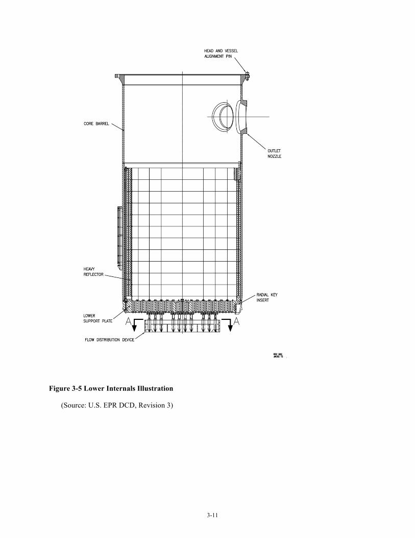
Figure 3-5 Lower Internals Illustration
(Source: U.S. EPR DCD, Revision 3)
3-12
3.1.2.2 High-Strength Fasteners
Iron-base stainless steel and nickel-base alloys are used for internals bolting and pins because of their good resistance to general corrosion in water environments. These alloys are used for reactor internals applications in both irradiated and non-irradiated locations. The most commonly used material in advanced PWR internals is strain hardened Type 316 stainless steel (allowed for core support use in ASME Code Case N-60-5). This material is used for threaded fasteners and locating pins, as well as for tie rods used to assemble the reflector assemblies. It is considered to be relatively resistant to SCC and IASCC in primary water environments. As a replacement bolting material in operating PWRs, this alloy has performed well to date. Strain hardening is limited by controlling the room temperature yield strength to 90 ksi (621 MPa) maximum. Nevertheless because of limited field experience, risk of degradation was generally considered to be well above the average for all bolting and pin applications.
Nickel Alloy X-750 (and the option of Alloy 718) will be used for some bolting applications, often in the case where the designer desired to match the thermal expansion coefficient of mating Alloy 690. Alloy X-750 has experienced PWSCC in operating PWRs, but it was concluded the material used at the time was not in an optimum heat treatment condition. For the advanced plant designs, the heat treatment condition will be optimized for PWSCC resistance (high temperature anneal, single step age per ASME SB-637, N07750, Type 3 or similar). Even so, it is known that this alloy can suffer SCC, even when in the optimum heat treatment condition if sustained tensile stresses are too high or if the component design includes sharp discontinuities that create localized stress concentrations. For this reason, X-750 in internals bolting applications was considered to be at a somewhat higher risk of degradation than the strain hardened Type 316 material.
For either material risk of degradation was considered somewhat elevated if the bolting received a significant neutron dose. Although there is no highly irradiated internals bolting in the new plant designs, some internals bolting will receive significant a neutron dose in a 60-year exposure (to near 3 dpa). Consequently, IASCC is a potential degradation mode with loss of ductility and toughness as secondary degradation concerns. Irradiation-enhanced relaxation will also contribute to loss of preload.
For units having stacked neutron reflectors, these designs include strain hardened Type 316 stainless steel tie rods that extends the full length of the neutron reflector assembly. Because of its location, the tie rod will receive significantly higher neutron fluence than any other internals bolting. The primary function of the tie rods is to facilitate assembly of the reflector stack and insertion of the assembly into the core barrel. However, at least one vendor has re-categorized these tie rods as core support based on NRC questions regarding seismic loading. As a result, there is some need to evaluate the function of the tie rods over a long service life. Since these rods will be subject to significant neutron fluence (although the specific EOL value depends on where the rods are located relative to the ID of the reflector rings), loss of preload due to stress relaxation is a potential degradation concern. Although stress relaxation is likely to occur, the concern is mitigated by the relatively low consequences since these tie rods are credited only as a secondary feature to address potential uplift of the reflector assembly during a seismic event. Conversely, should the tie rod preload be high, IASCC is a possibility.
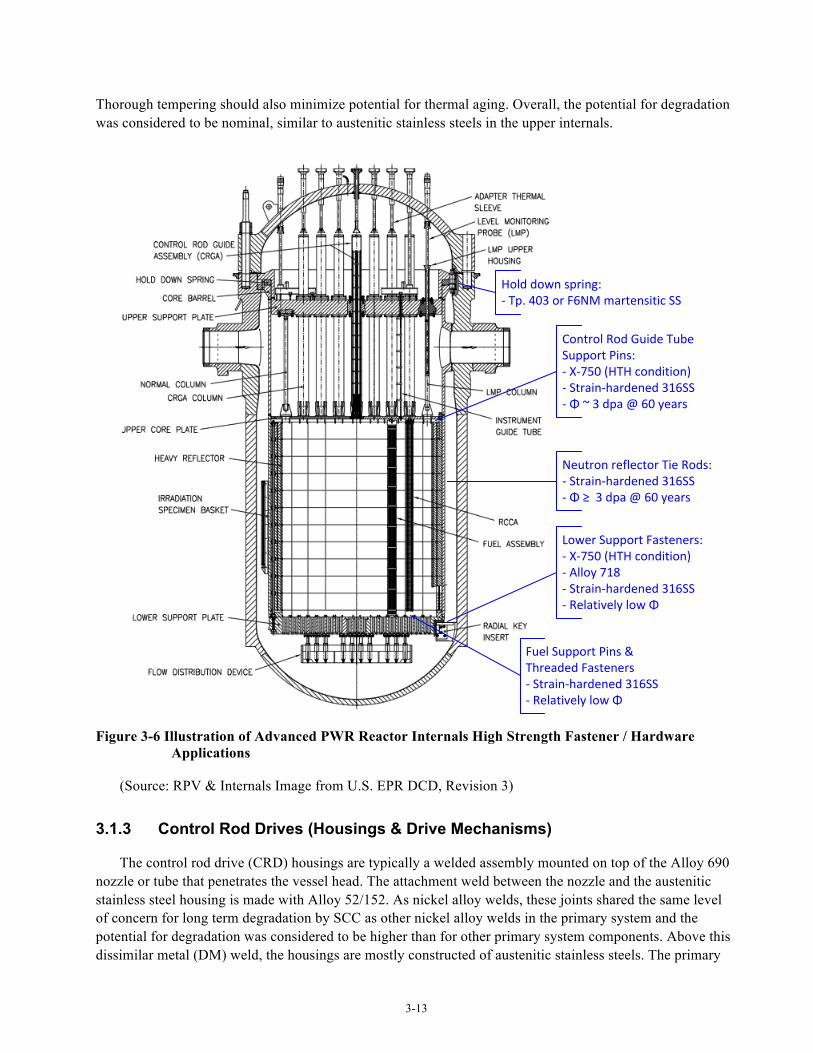
Although not strictly a fastener, moderately high strength martensitic stainless steel, typically Type 403 Mod. is used for the internals hold down spring. The primary concern for this material is embrittlement by long-term thermal aging. SCC is also a potential degradation mechanism, but in all cases the material for this component is deployed in a heat treatment condition considered optimum for SCC resistance (i.e. H1100).
3-13
Thorough tempering should also minimize potential for thermal aging. Overall, the potential for degradation was considered to be nominal, similar to austenitic stainless steels in the upper internals.
Hold down spring: -‐ Tp. 403 or F6NM martensitic SS
Control Rod Guide Tube Support Pins:-‐ X-‐750 (HTH condition)-‐ Strain-‐hardened 316SS-‐ Φ ~ 3 dpa @ 60 years
Neutron reflector Tie Rods:-‐ Strain-‐hardened 316SS-‐ Φ ≥ 3 dpa @ 60 years
Lower Support Fasteners:-‐ X-‐750 (HTH condition)-‐ Alloy 718-‐ Strain-‐hardened 316SS-‐ Relatively low Φ
Fuel Support Pins & Threaded Fasteners-‐ Strain-‐hardened 316SS-‐ Relatively low Φ
Figure 3-6 Illustration of Advanced PWR Reactor Internals High Strength Fastener / Hardware
Applications
(Source: RPV & Internals Image from U.S. EPR DCD, Revision 3)
3.1.3 Control Rod Drives (Housings & Drive Mechanisms)
The control rod drive (CRD) housings are typically a welded assembly mounted on top of the Alloy 690 nozzle or tube that penetrates the vessel head. The attachment weld between the nozzle and the austenitic stainless steel housing is made with Alloy 52/152. As nickel alloy welds, these joints shared the same level of concern for long term degradation by SCC as other nickel alloy welds in the primary system and the potential for degradation was considered to be higher than for other primary system components. Above this dissimilar metal (DM) weld, the housings are mostly constructed of austenitic stainless steels. The primary
3-14
degradation concern is intergranular SCC (IGSCC) driven by elevated oxygen levels resulting from air trapped in the top end of the housing during filling of the reactor vessel. Advanced PWR designs have addressed this concern by using materials resistant to weld sensitization (low carbon grades such as 304L, 304LN, 316LN, and stabilized 347 with carbon limited to 0.04%) and therefore more resistant to IGSCC in oxygenated water. In addition, the advanced plant designs include provision for vacuum filling or vented filling of the reactor vessel to limit the potential for entrapment of oxygen. Consequently, the potential for long-term degradation was considered to be no different from other pressure boundary stainless steel components (i.e., about average compared to other primary system components). Some drive housings also include a martensitic stainless steel section of F6NM or Type 415. This tube is welded to austenitic stainless steel sections on either side using Alloy 52/152. The welds were considered to be at risk of long term degradation, similar to other nickel alloy welds. The martensitic material is used in a heat treatment condition generally considered resistant to SCC and consequently the potential for degradation is judged to be no different than for the austenitic stainless steel pressure housing components. Degradation of mechanical properties by long-term thermal aging is also possible for martensitic stainless steels, but the likelihood of significant embrittlement is very low because this alloy is expected to be thermodynamically very stable in the high temperature temper condition (H1100) specified by vendors. Further, all advanced PWRs incorporate a Tcold reactor vessel head design. This design approach limits the operating temperature of CRD components to a temperature near the cold leg temperature (550 °F), instead of a temperature near the hot leg temperature (>600°F). Although not specifically introduced to address thermal embrittlement concerns, it has that effect since thermal embrittlement is a temperature dependent, solid-state diffusion driven process.
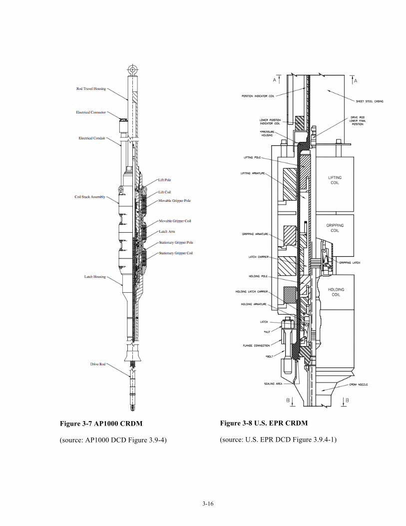
The control rod drive mechanism (CRDM) resides inside the drive housing and is exposed to reactor coolant. The materials of construction are similar to those in operating plants that have performed very well over time. For the large advanced PWRs, these materials are for the most part the same as those used for other components in the primary system including austenitic stainless steels (unstabilized 304/304L/316/316L and stabilized 316Ti/347), martensitic stainless steels (Type 403 Mod. or Type 410) and high strength nickel-base Alloy X-750. However, drives do include use of a wear resistant cobalt base alloy (Haynes 25) and a moderate strength nickel-base alloy (Alloy 625).
By comparison to the same or similar alloys used elsewhere in the primary systems, it can be observed that the austenitic stainless steel components of the drive are about average with respect to potential for long-term degradation with SCC as the most likely degradation mode. The SCC potential can vary somewhat within the drive depending on whether the individual component is welded and the level of sustained tensile stress. In any case, austenitic stainless steels generally perform well in PWR primary water provided oxygen is not entrapped in stagnant regions. Likewise, martensitic stainless steels in an optimum heat treatment condition perform well in PWR primary water, so that the potential for long-term degradation, primarily due to SCC, is considered to be similar to the stainless steel pressure housing components. Alloy X-750 components are considered to have a somewhat higher potential for degradation. The probability of degradation conclusions and associated rationales are similar to those for unirradiated reactor internals X-750 hardware. Again, the potential for SCC is the main concern and can vary depending on the level of sustained tensile stress including consideration of stress concentrations.
For the materials used in CRDs that are not used elsewhere in the primary system, projection of potential for long-term materials degradation may be made considering performance experience. Haynes 25 has been commonly used in CRDs in both PWRs and BWRs over the operating life of the plants to date. Although a wear resistant alloy, there may be some potential for wear concerns in long-term operation, but based on operating experience the risk appears to be nominal. Alloy 625 (UNS N06625) is somewhat more difficult to rank with respect to potential for long-term degradation. Alloy 625 is a Ni-Cr-Mo alloy with the chromium
3-15
content falling between Alloy 600 and Alloy 690. The alloy is also stabilized with a significant niobium addition (3.15-4.15%). It is commonly used in aerospace and chemical processing applications. In the solution-annealed condition, room temperature strength is somewhat greater than Alloy 690. It is being used for various small parts in the CRD that were formerly made of Alloy 600. If the potential for PWSCC to occur in this application is considered to be similar to Alloy 690 reactor internals components, then the relative risk may be projected to be somewhat higher than for other primary system components. As with Alloy 690, the risk is based on long-term performance uncertainties associated with the use of high Cr nickel alloys, not with any specific vulnerabilities observed in service.
Finally, the CRDM is an active assembly. That is, there are moving parts during plant operation at least at certain intervals. For long-term operation then, there is some potential for degradation by wear and fatigue. Although the major wear locations are addressed by use of hardfacing and wear resistant alloys, operation for very long times may result in wear in other components in the assembly. Likewise, operation for 60+ years may introduce fatigue and/or environmentally assisted fatigue issues in components that are not normally considered to be susceptible to degradation by fatigue.
3.1.4 Steam Generators
Steam generator designs for the large advanced PWRs are similar with respect to materials of construction although there is some variation in the internals. In evaluating expected materials performance, it is useful to divide the steam generator into component groups based on environment and function. These groups include 1) tubes, 2) tube supports and internals, and 3) secondary-side shells and head. The channel head and tubesheet are not specifically included in this section. These components are considered to be in the same category as other primary system pressure boundary components (evaluated in Section 3.1.1). This is reasonable because the materials are the same (LAS clad with stainless steel or nickel-base alloy), as is the environment. Therefore, the vulnerabilities to materials degradation may be considered to be the same as those discussed for other unirradiated pressure vessels in the primary system. Internal to the channel head assembly an Alloy 690 divider plate is welded between the channel head and tube sheet. The degradation concerns for this component are similar to other Alloy 690 structural components with the perceived risk above average relative to all components. The primary degradation mode is PWSCC with long-term exposure. As a unique feature, the AP1000 design has the primary recirculation pumps attached directly to the channel head outlet nozzles. However, this novel configuration was not considered to introduce any new or different materials degradation concerns relative to other channel head designs.
All the large advanced PWR steam generators use Alloy 690 in the thermally treated (TT) heat treatment condition for the U-tubes. These tubes are exposed to primary system water on the inside and secondary system water on the outside. Therefore, these tubes see two different environments with different degradation concerns. Historically Alloy 600 in the same application has been seen to be susceptible to SCC on the secondary side and, to a lesser extent, on the primary side. Although Alloy 690 has been developed and qualified as the preferred material for replacement and new steam generators, the relative risk of long-term degradation was considered to be well above average. As with other Alloy 690 applications, this concern was primarily driven by the lack of long-term operating experience.
3-16
Figure 3-7 AP1000 CRDM
(source: AP1000 DCD Figure 3.9-4)
Figure 3-8 U.S. EPR CRDM
(source: U.S. EPR DCD Figure 3.9.4-1)
3-17
In addition to SCC concerns for cold-worked alloy 690 in primary water (Section 3.1.1.2), it has been shown to be susceptible to SCC in high pH, lead-contaminated second-side environments in laboratory tests. Based on experience in operating steam generators, such an environment may form at line-contact crevices in the new systems as well. High cycle fatigue and wear were cited as additional contributing factors in the assessment. Notably, detection risk is judged to be relatively low due to the robust NDE capabilities that have been developed over many years to address degradation of steam generator tubing.
Materials selection is somewhat mixed for other steam generator secondary-side internals, but with some general trends. Plain carbon steel is used for some components, as was commonly the case for the operating plant steam generators. Carbon steel is susceptible to general corrosion, pitting and flow-accelerated corrosion. Consequently, the new plant steam generator designs apply other alloys selectively for components considered to be at risk of these degradation phenomena. Tube spacers and braces are fabricated of ferritic stainless steel (Type 405), martensitic stainless steel (Type 410), or austenitic stainless steel (Type 304) to address the previous concern for tube denting generated by the corrosion of plain carbon steel spacers. For these components, the main degradation concern was wear with high-cycle fatigue as a related potential issue. SCC concerns are low since these materials have performed well in service to date and do not contain any welds.
The feedwater systems employ low alloy steels (e.g. SA-335, P11 or P22), austenitic stainless steels (316, 316L), and some Alloy 690. Potential for materials degradation was generally considered to be near average to below average for most of these materials in this application. The potential degradation concerns were pitting and corrosion for the LAS components and SCC for the austenitic alloys. The alloy content in the LAS, particularly the chromium, was considered sufficient to mitigate flow-accelerated corrosion. Primary and secondary moisture separators remain mostly plain carbon steel with some use of LAS in specific locations in some designs. Carbon steel components in high flow areas (e.g. the moisture separators) were generally considered to be at above average risk of degradation in long term operation because of concerns for flow-accelerated corrosion. Carbon steel for other components such as tube bundle wrappers in relatively low flow environments were considered to be below average with respect to potential for long term degradation.
Steam generator shells, heads and nozzles are fabricated of unclad LAS (predominately SA-508, Gr. 3, Cl. 2). Historically steam generator secondary shells have performed well with few, if any, significant materials degradation issues. Some early designs have concerns for relatively high fatigue usage at the feedwater nozzles, but this issue is considered to be adequately managed by monitoring of thermal cycles. Even so, the feedwater nozzles for the advanced plant steam generators were considered to be at a somewhat higher risk of degradation than the balance of the secondary shell components. Nevertheless, the feedwater nozzle risk compared to all components was only about average with the balance of the shell components falling well below average. This includes the access hole covers and some carbon steel instrument penetrations. All of the advanced plant designs reviewed include an Alloy 690 flow restrictor welded into the steam outlet nozzle. In this application (very low applied loads), the flow restrictor and the attaching welds were considered to be at a low risk of degradation with SCC cited as the primary potential concern.
3-18
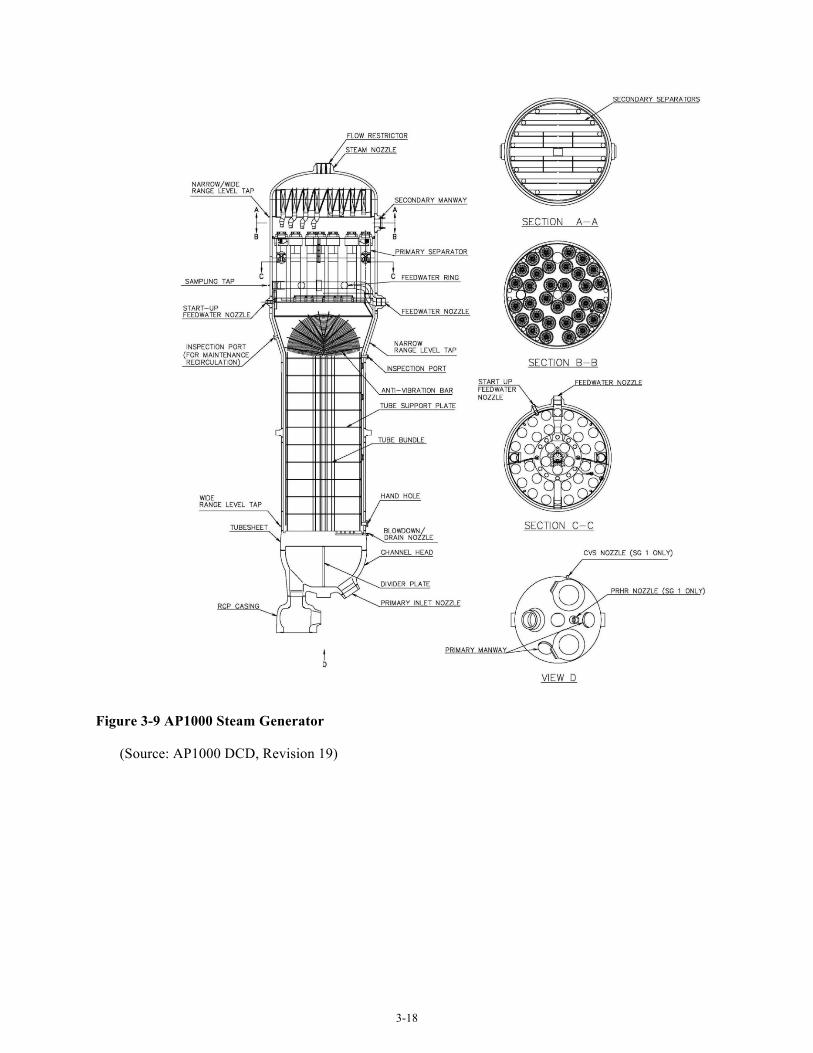
Figure 3-9 AP1000 Steam Generator
(Source: AP1000 DCD, Revision 19)
3-19
3.2 FMEA Summary
Tables 3-1 through 3-4 provide a summary of FMEA conclusions for advanced PWR primary system components. In these summary tables, note that the results presented are in comparison with other components/materials used in advanced PWRs. On an absolute scale, there are no truly high risk components in comparison with the older materials and component configurations used in Gen. II reactor designs.
The most significant primary pressure boundary component degradation concerns occur for beltline shells and for Alloy 690/52/152 components. In this area, ongoing R&D focused on resolving PWSCC uncertainties for Gen. II reactor repair and replacement applications is directly applicable to large advanced PWR designs, although to address new plants a significant increase in service life must be considered. Whereas Alloy 690, 52 and 152 materials used in repairs and replacements will have service lives approaching 60 years, the expectation for any new plant is that 80 years of service should be attainable for primary system structural components.
With regard to beltline shells and welds, the predicted EOL fluence is not significantly different than that expected for Gen. II reactors and is, in most cases, actually lower. The use of high toughness materials and specification of material chemistry controls substantially reduces irradiation embrittlement concerns. However, long-term performance is considered particularly important for vessel shells considering the high safety, economic and regulatory impacts that would result from identification of in-service degradation.
The most significant degradation concerns associated with reactor internals include core shroud structures exposed to high neutron dose and high strength fasteners. For core shroud structures, the high EOL neutron dose results in some concern associated with long-term performance. EOL neutron dose will be significantly higher than in Gen. II plants, and depending on peak temperatures resulting from gamma heating, significant void swelling could occur. IASCC remains a general concern for stainless steel internals and becomes a significant concern ror welded core shroud designs. All high-strength reactor internal fasteners are considered to be at somewhat higher risk of degradation, regardless of fluence exposure. Current research efforts have been primarily focused on high fluence baffle bolting. For advanced PWR designs, the elimination of high fluence bolting suggests that future research should focus on understanding critical margins to SCC susceptibility, SCC initiation and related factors.
The most significant degradation concerns associated with CRD components occur for nickel-base alloy components, including Alloys 690, 52, 152 and X-750. The primary degradation concern is PWSCC, although the potential for corrosion fatigue interaction is also noted.
For the steam generators, the Alloy 690TT tubing specified for use in all large advanced PWR designs has performed well in service for more than 20 years. Regardless, there are some remaining concerns related to vulnerabilities resulting from off-normal chemistry conditions, particularly occluded chemistries containing lead. This concern results in a somewhat higher than average risk of degradation for the tubing material when considering that the baseline expectation is 60 or more years of good performance. Given that 60 or more years of service is expected from these steam generators, there is some concern regarding the corrosion margins included in the carbon steel materials used for steam generator upper internals (steam separator and dryer assemblies). Should corrosion estimates be inadequate, significant repair costs could result.
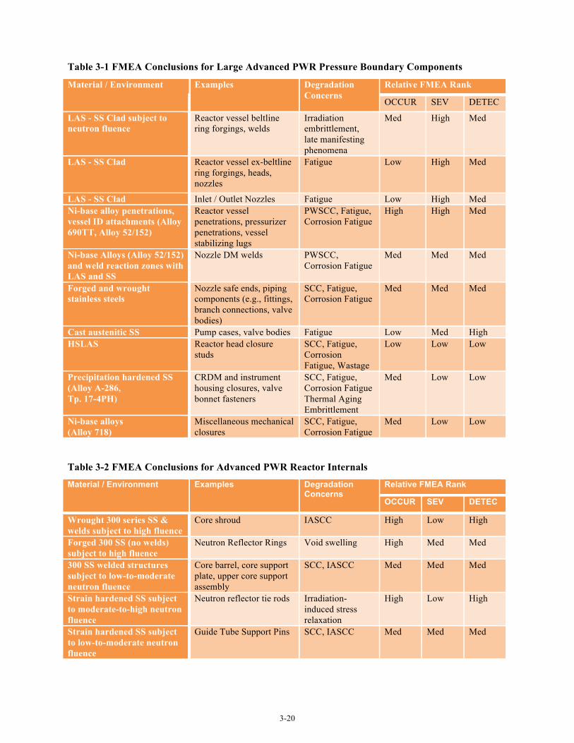
3-20
Table 3-1 FMEA Conclusions for Large Advanced PWR Pressure Boundary Components
Material / Environment Examples Degradation Concerns
Relative FMEA Rank
OCCUR SEV DETEC
LAS - SS Clad subject to neutron fluence
Reactor vessel beltline ring forgings, welds
Irradiation embrittlement, late manifesting phenomena
Med High Med
LAS - SS Clad Reactor vessel ex-beltline ring forgings, heads, nozzles
Fatigue Low High Med
LAS - SS Clad Inlet / Outlet Nozzles Fatigue Low High Med Ni-base alloy penetrations, vessel ID attachments (Alloy 690TT, Alloy 52/152)
Reactor vessel penetrations, pressurizer penetrations, vessel stabilizing lugs
PWSCC, Fatigue, Corrosion Fatigue
High High Med
Ni-base Alloys (Alloy 52/152) and weld reaction zones with LAS and SS
Nozzle DM welds PWSCC, Corrosion Fatigue
Med Med Med
Forged and wrought stainless steels
Nozzle safe ends, piping components (e.g., fittings, branch connections, valve bodies)
SCC, Fatigue, Corrosion Fatigue
Med Med Med
Cast austenitic SS Pump cases, valve bodies Fatigue Low Med High HSLAS Reactor head closure
studs SCC, Fatigue, Corrosion Fatigue, Wastage
Low Low Low
Precipitation hardened SS (Alloy A-286, Tp. 17-4PH)
CRDM and instrument housing closures, valve bonnet fasteners
SCC, Fatigue, Corrosion Fatigue Thermal Aging Embrittlement
Med Low Low
Ni-base alloys (Alloy 718)
Miscellaneous mechanical closures
SCC, Fatigue, Corrosion Fatigue
Med Low Low
Table 3-2 FMEA Conclusions for Advanced PWR Reactor Internals
Material / Environment Examples Degradation Concerns
Relative FMEA Rank
OCCUR SEV DETEC
Wrought 300 series SS & welds subject to high fluence
Core shroud IASCC High Low High
Forged 300 SS (no welds) subject to high fluence
Neutron Reflector Rings Void swelling High Med Med
300 SS welded structures subject to low-to-moderate neutron fluence
Core barrel, core support plate, upper core support assembly
SCC, IASCC Med Med Med
Strain hardened SS subject to moderate-to-high neutron fluence
Neutron reflector tie rods Irradiation-induced stress relaxation
High Low High
Strain hardened SS subject to low-to-moderate neutron fluence
Guide Tube Support Pins SCC, IASCC Med Med Med
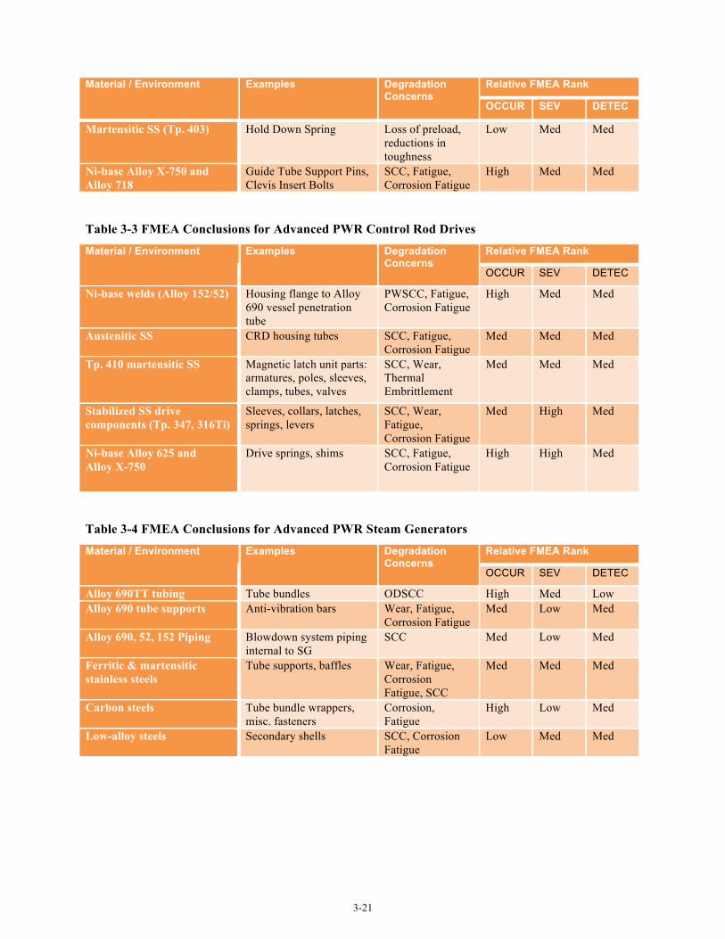
3-21
Material / Environment Examples Degradation Concerns
Relative FMEA Rank
OCCUR SEV DETEC
Martensitic SS (Tp. 403) Hold Down Spring Loss of preload, reductions in toughness
Low Med Med
Ni-base Alloy X-750 and Alloy 718
Guide Tube Support Pins, Clevis Insert Bolts
SCC, Fatigue, Corrosion Fatigue
High Med Med
Table 3-3 FMEA Conclusions for Advanced PWR Control Rod Drives
Material / Environment Examples Degradation Concerns
Relative FMEA Rank
OCCUR SEV DETEC
Ni-base welds (Alloy 152/52) Housing flange to Alloy 690 vessel penetration tube
PWSCC, Fatigue, Corrosion Fatigue
High Med Med
Austenitic SS CRD housing tubes SCC, Fatigue, Corrosion Fatigue
Med Med Med
Tp. 410 martensitic SS Magnetic latch unit parts: armatures, poles, sleeves, clamps, tubes, valves
SCC, Wear, Thermal Embrittlement
Med Med Med
Stabilized SS drive components (Tp. 347, 316Ti)
Sleeves, collars, latches, springs, levers
SCC, Wear, Fatigue, Corrosion Fatigue
Med High Med
Ni-base Alloy 625 and Alloy X-750
Drive springs, shims SCC, Fatigue, Corrosion Fatigue
High High Med
Table 3-4 FMEA Conclusions for Advanced PWR Steam Generators
Material / Environment Examples Degradation Concerns
Relative FMEA Rank
OCCUR SEV DETEC
Alloy 690TT tubing Tube bundles ODSCC High Med Low Alloy 690 tube supports Anti-vibration bars Wear, Fatigue,
Corrosion Fatigue Med Low Med
Alloy 690, 52, 152 Piping Blowdown system piping internal to SG
SCC Med Low Med
Ferritic & martensitic stainless steels
Tube supports, baffles Wear, Fatigue, Corrosion Fatigue, SCC
Med Med Med
Carbon steels Tube bundle wrappers, misc. fasteners
Corrosion, Fatigue
High Low Med
Low-alloy steels Secondary shells SCC, Corrosion Fatigue
Low Med Med
4-1
4.0 Evaluation of B&W mPowerTM Reactor
This section provides a preliminary assessment of materials issues and R&D needs for the B&W mPower reactor which is still under active design at the time this report was prepared. Consequently, the design configurations and materials selections shown in this report are potentially subject to changes as the design evolves. The approach and conclusions reached in this section are built on the evaluation of large advanced PWRs from Section 3. Although there are some fundamental differences between the mPower configuration and that of traditional PWRs, from the perspective of materials selection, fabrication practices and environmental exposure, the mPower design closely resembles that of large advanced PWRs. Where there are significant differences, these aspects are highlighted in the following sections.
4.1 Component Descriptions and General Discussion
Most of the functional components of large PWR designs are retained. The mPower primary pressure boundary includes a reactor pressure vessel, pressurizer, steam generator, and primary coolant pumps. The reactor vessel houses reactor internals, and control rod drives. A key design change is an “integration” of the reactor vessel, steam generator, and pressurizer functions into a single vessel assembly. A second notable design change is placing the CRDMs completely inside the reactor pressure vessel. The overall assembly of the mPower reactor primary/secondary system is illustrated in Figure 4-1. The upper and lower pressure vessel sections are joined by a bolted connection at a “mid” flange.
The “lower vessel” section contains the core, core support structures, CRDMs, and control rod guides. The lower vessel itself is similar in configuration and function to a traditional PWR reactor vessel, with the notable exception that the CRDMs themselves are contained within the vessel. The remaining elements of the primary system (i.e., steam generator, pressurizer and reactor coolant pumps) are consolidated into the “upper vessel” that mounts above the lower vessel. Over the length of the steam generator section, the vessel outer shell forms the steam generator secondary side pressure boundary and includes both the feedwater inlet and steam outlet nozzles. The steam generator is a once-through design, with tubes arranged around a central riser. This riser functions as the primary system “hot leg” and provides a flow path from core exit region to the reactor coolant pump intake plenum. The plenum also functions as a shelf for supporting eight canned motor RCPs. Above this plenum, a connected dome region provides the pressurizer function.
The primary “hot leg” flow exits the top of the core in the mPower design and is directed to the upper end of the steam generator section by the central riser. As such, the riser is primary pressure boundary even though it is in the center of the upper vessel. At the upper end of the riser, flow is directed radially outward, pumped through eight RCP inlets, and discharged downward into the steam generator upper plenum and through the upper tubesheet and tube bundle. At the lower tubesheet, the cold leg flow is directed radially outward into the lower vessel section annulus region between the core basket and lower vessel wall, then turns at the vessel lower head and proceeds upward into and through the core.
It should be noted that in contrast with large advanced PWRs, the B&W mPower reactor uses control rods to suppress excess reactivity rather than soluble boron to control reactivity. From a materials corrosion and EAC perspective, relatively little is affected by this change in primary chemistry due to the low electrochemical potential in the hydrogenated water coolant similar to that for PWR primary circuits.
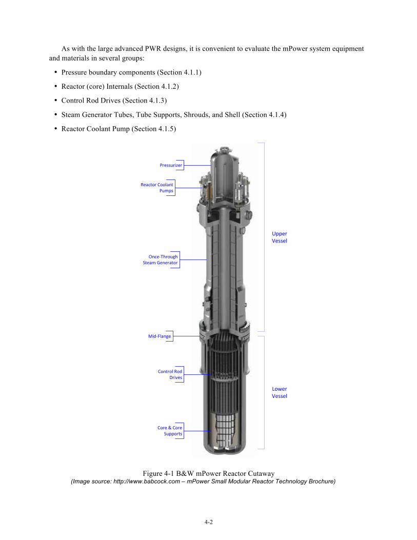
4-2
As with the large advanced PWR designs, it is convenient to evaluate the mPower system equipment and materials in several groups:
• Pressure boundary components (Section 4.1.1)
• Reactor (core) Internals (Section 4.1.2)
• Control Rod Drives (Section 4.1.3)
• Steam Generator Tubes, Tube Supports, Shrouds, and Shell (Section 4.1.4)
• Reactor Coolant Pump (Section 4.1.5)
Figure 4-1 B&W mPower Reactor Cutaway (Image source: http://www.babcock.com – mPower Small Modular Reactor Technology Brochure)
Upper Vessel
Lower Vessel
Pressurizer
Reactor Coolant Pumps
Once-‐Through Steam Generator
Mid-‐Flange
Core & Core Supports
Control Rod Drives
4-3
4.1.1 mPower Primary System Pressure Boundary Components
The mPower reactor system pressure boundary components are illustrated in Figure 4-2.
4.1.1.1 Pressure Vessel Shells, Heads, Flanges, Nozzles and Welds
Primary pressure boundary components include the lower vessel shell and bottom head, flanges, upper and lower tubesheets, riser shell, pump annulus shell, pressurizer/pump shelf, pressurizer shell and head, and the pump housing. Based on design information, the main materials of construction for these components are expected to be LAS forgings according to SA-508, Gr. 3, Class 1 or Class 2. Class 1 and Class 2 are identical chemically, but Class 2 has somewhat higher strength owing to variations in heat treatment. Class 1 will be used for the beltline region of the reactor vessel. The balance of both the primary and secondary pressure retaining components will be either Class 1 or Class 2. This includes the integrated lower tubesheet/upper vessel flange, mid flange, upper tubesheet, secondary shells, pressurize shell and dome, main steam and feedwater nozzles, steam generator riser, etc. Manway covers, handhold covers, and inspection port covers will be fabricated of SA-533, Type B LAS plate.
Components that are not exclusively primary system pressure boundary include the steam generator upper and lower tubesheets, which are an interface between the primary and secondary systems, as is the steam generator riser. The upper vessel outer shell and associated access ports, and steam and feedwater nozzles, are secondary pressure boundary only.
Surfaces in primary side exposed to reactor coolant will be clad with stainless steel (308L/309L) or with Alloy 52/152. The mid flange is an SA-508, Gr. 3 forging sandwiched between the lower vessel flange and the upper vessel flange. Structural welds will be made with compatible LAS weld filler. These materials are the same as used for large advanced PWR designs so given similar water chemistry and operating temperatures, materials degradation concerns are essentially the same.
The mPower beltline shell ring design calls for low alloy steel, SA-508, Gr. 3, Cl. 1, the same as for all the large advanced PWRs. Chemistry for the beltline shell and adjacent welds will be controlled to limit embrittlement by neutron irradiation and the initial RTNDT is specified to be -10°F (-23°C) similar to the large PWR units. The estimated 60 year fluence for the mPower design is enveloped by the large advanced PWR designs. Current calculations for the mPower design predict a peak inside surface fluence to be at the low end of the range projected for large advanced PWRs. However, additional refinement in the calculation may allow for further reduction in the estimated EOL fluence. This is a reasonable result given that the mPower design uses a solid stainless steel reflector assembly as the core former inside the core basket (a.k.a. core barrel in large units). This is a similar design to the large advanced PWRs that have predicted EOL fluence to the low side of the range. The neutron reflector assembly provides significant shielding of the reactor vessel beltline forgings. Beltline copper content will be limited to low levels, similar to the large advanced PWR designs. As a result, the shift in RTNDT and adjusted reference temperature (ART) for 60 year operation is expected to be enveloped by the large advanced PWR designs.
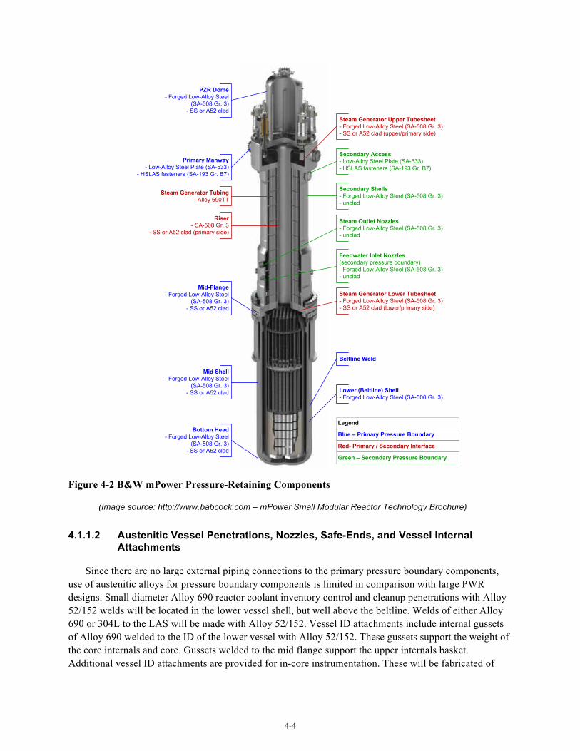
4-4
Steam Generator Upper Tubesheet- Forged Low-Alloy Steel (SA-508 Gr. 3)- SS or A52 clad (upper/primary side)
Mid-Flange- Forged Low-Alloy Steel
(SA-508 Gr. 3)- SS or A52 clad
Lower (Beltline) Shell- Forged Low-Alloy Steel (SA-508 Gr. 3)
Secondary Shells- Forged Low-Alloy Steel (SA-508 Gr. 3)- unclad
Steam Outlet Nozzles- Forged Low-Alloy Steel (SA-508 Gr. 3)- unclad
Feedwater Inlet Nozzles(secondary pressure boundary)- Forged Low-Alloy Steel (SA-508 Gr. 3)- unclad
Steam Generator Lower Tubesheet- Forged Low-Alloy Steel (SA-508 Gr. 3)- SS or A52 clad (lower/primary side)
Beltline Weld
Mid Shell- Forged Low-Alloy Steel
(SA-508 Gr. 3)- SS or A52 clad
Bottom Head- Forged Low-Alloy Steel
(SA-508 Gr. 3)- SS or A52 clad
PZR Dome- Forged Low-Alloy Steel
(SA-508 Gr. 3)- SS or A52 clad
Steam Generator Tubing- Alloy 690TT
Riser- SA-508 Gr. 3
- SS or A52 clad (primary side)
Primary Manway- Low-Alloy Steel Plate (SA-533)
- HSLAS fasteners (SA-193 Gr. B7)
Secondary Access- Low-Alloy Steel Plate (SA-533)- HSLAS fasteners (SA-193 Gr. B7)
Legend
Blue – Primary Pressure Boundary
Red- Primary / Secondary Interface
Green – Secondary Pressure Boundary
Figure 4-2 B&W mPower Pressure-Retaining Components
(Image source: http://www.babcock.com – mPower Small Modular Reactor Technology Brochure)
4.1.1.2 Austenitic Vessel Penetrations, Nozzles, Safe-Ends, and Vessel Internal Attachments
Since there are no large external piping connections to the primary pressure boundary components, use of austenitic alloys for pressure boundary components is limited in comparison with large PWR designs. Small diameter Alloy 690 reactor coolant inventory control and cleanup penetrations with Alloy 52/152 welds will be located in the lower vessel shell, but well above the beltline. Welds of either Alloy 690 or 304L to the LAS will be made with Alloy 52/152. Vessel ID attachments include internal gussets of Alloy 690 welded to the ID of the lower vessel with Alloy 52/152. These gussets support the weight of the core internals and core. Gussets welded to the mid flange support the upper internals basket. Additional vessel ID attachments are provided for in-core instrumentation. These will be fabricated of
4-5
either 304L stainless steel or Alloy 690. Penetration attachments and attachments to interior surfaces of the primary pressure boundary of stainless steel or Alloy 690 will be welded using Alloy 52/152.
Low carbon austenitic stainless steels in PWR primary service have performed well and are considered to be about average with respect to potential for long-term materials degradation compared to all components in a new design PWR. Alloy 690 and its weld metals have been used for the past ~25 years with an excellent operating record. Nevertheless, Alloy 690 and its weld metals are generally considered to be at somewhat higher risk of long term degradation because operating experience with these alloys is comparatively limited and some laboratory testing has shown crack growth rates of concern for selected material conditions.
4.1.1.3 Pressure-Retaining Bolting
The mPower reactor vessel main closure bolting will be fabricated from SA-540, Gr. B24, Class 3. This is the same high strength low alloy steel as used by most of the large advanced PWR designs. Bolting for smaller flanged closures such as manway covers and inspection ports on both the primary and secondary side will be SA-193, Grade B7, also commonly used in the large unit designs. Since the bolting materials are the same as for the large PWRs, the discussion of potential degradation concerns from the large advanced PWR evaluation section applies. The mPower design currently plans to control hardness of the SA-540 materials according to the ASME specification in addition to the 150 ksi yield strength limit required by R.G 1.65. This may create a minor SCC concern, since hardness levels up to approximately Rockwell C-42 could be allowed for some bolt diameters. All of the large advanced PWRs limit hardness to Rockwell C-40 or less to mitigate potential for SCC from periodic wetting. This concern is offset by the fact that for the mPower design there is no potential for boric acid corrosion of the primary pressure boundary bolting. In consideration of the difference in hardness limits, potential for long term materials degradation of the mPower main closure bolting is considered to be slightly elevated compared to the large unit reactor vessel head closure bolting, but still considered to be below average compared to all components. For the SA-193, Gr. B7 bolting hardness will be limited by the specification to well below Rockwell C-40. At this time, no high strength corrosion-resistant alloys (e.g. 17-4PH, A-286, X-750) have been identified as being used for pressure boundary bolting in the mPower design.
4.1.2 Reactor Internals
The design of mPower core internals (Figure 4-3) is very similar to design approaches being used in large advanced PWRs. The core former will be created with a stack of stainless steel forged rings machined to the shape of the core boundary. Figure 3-4 in the large advanced PWR evaluation section illustrates a stacked ring core former. In this design, the space between the outer periphery of the core and the inside of the core barrel is solid stainless steel. Not only do the ring forgings form the core boundary, but they also provide neutron shielding of the core barrel and reactor vessel wall.
However a few reactor internals features are different than large advanced PWRs:
• The mPower design does not employ tie rods in the core former assembly. For the large advanced PWRs using a reflector assembly of stacked rings, tie rods that extend vertically through the stack are included to facilitate assembly and insertion into the core barrel. In one case, these tie rods are currently given credit for some core support function.

4-6
• Since the CRDMs are entirely contained within the reactor vessel, additional internals structure to guide and support the CRDMs (described as the “CRDM Region” by B&W) above the control rod guide frame, and CRDM power must be routed inside the vessel.
• Since the core exit “hot leg” is a vertical riser (instead of radially oriented outlets), core barrel outlets are eliminated and a “riser cone” assembly is added above the upper internals basket that carries CRDMs and the CRD guide assembly. The riser cone provides the separation between the hot leg flow rising from the core and the downward cold leg flow exiting the lower tubesheet.
4.1.2.1 Structures & Welds
The materials list for the mPower reactor internals structures and welds is expected to be very short, with virtually all the structural components being made of 304L stainless steel, with 304 as an option for a few selected items. If Type 304 is used for a welded assembly, the carbon content will be restricted to 0.03 wt% maximum. Product forms of these alloys used include plate, bar, forgings, pipe, tube, and bolting. Some of the major components or component assemblies made of 304/304L are as follows with the order approximately from the bottom of the core support to the top of the internals where the riser cone directs core flow into the steam generator riser:
• Lower core plate
• Core Basket (called the Core Barrel in large PWRs)
• Core Former Rings (analogous to the reflector rings in U.S. EPR and APWR)
• Control Rod Guide Frames
• CRDM
• Upper Internals Basket
• Riser Transition
• Riser Cone
In addition, a number of pins, aligners, guide blocks, etc. will be 304L where the higher strength of the strain hardened material is not required. Above the steam generator riser inside the pressurizer and pump annulus shell there are additional internal components that will be fabricated using 304L or 316L stainless steel, or Alloy 690.
Weld filler metals for assembly of the reactor internals will be predominately 308L stainless steel with optional use of 316L or 309L. Ferrite in stainless steel filler metals is controlled to the range of 5 to 20 FN (ferrite number). For welding of stainless steel to Alloy 690 or Alloy 690 to itself, Alloys 52/152 will be used. It is intended to use variants of these alloys that provide improved weldability. Any welding of stainless steel or Alloy 690 to LAS pressure-retaining material (such as the upper internals basket to the mid flange) will also be performed using Alloy 52/152.
In assessing long-term material performance for the mPower reactor internals, it should first be noted that all of the materials used in the design are also used widely in the large advanced PWRs. Consequently, direct comparisons can be made and expected performance in the large PWR designs can be applied to the analogous components in the mPower design. For the unirradiated internals, austenitic stainless steels have performed well in operating PWRs and are expected to do so in the advanced PWR
4-7
designs. Overall, most of these stainless steel components were considered to be about average with respect to potential long-term degradation when compared to all primary system components. Degradation concerns focus primarily on the potential for SCC, especially in the event of off-normal water chemistry (e.g. oxygen intrusion or trapped oxygen in stagnant regions) and excessive cold work introduced in fabrication. These concerns nominally also apply to the mPower design. Although the potential for off-normal chemistry events cannot be well characterized based on the limited design information available, the compact design (including internally mounted CRDMs) and lack of external primary piping systems, would seem to limit the potential for entrapped oxygen. Fabrication processes that can introduce cold work (cold bending and forming) will not be used, with the possible exception that the core basket shells may be fabricated by cold rolling. Machining practices that limit introduction of surface cold work will be applied. The overall level of concern is mitigated by the use of low carbon stainless steel throughout for welded components. Since the core outlet temperature in this design is relatively low (606°F), the material performance expectations are enveloped by the large PWR units. This peak temperature also mitigates the concern for thermal aging of stainless steel weld filler metals, which has already been addressed by the limitation on maximum ferrite content and carbon content. It is noted that the large PWRs do apply a stricter ferrite limit to 316/316L filler metals (usually 14 or 16 FN maximum) because molybdenum accelerates thermal aging embrittlement.
For the highly irradiated internals (mainly the 304L core former rings and the core basket), the concerns for long-term material degradation (void swelling, IASCC and neutron embrittlement) are the same as for the large PWRs. For the large PWRs, the highly irradiated internals were considered to have well above average potential for degradation in comparison with other primary system components. It can be assumed that the core former will be well over the threshold fluence for void swelling at least in some locations similar to large advanced PWRs. Fluence levels will certainly be reached for IASCC susceptibility and for neutron embrittlement and the associated loss of toughness. However, since it is currently assumed the mPower core former will be assembled from stacked rings without cold forming or welding, the concern for IASCC is somewhat reduced, as it is for the large units that also employ this type of core former design. There remains some uncertainty with respect to potential for void swelling and how it may affect the stacked ring design. A preliminary analysis of gamma heating in the core former suggests that peak temperatures will not exceed 660°F (349°C). While this is below the nominal lower bound temperature for void swelling in fast reactors, there is evidence that void swelling will occur in PWRs at lower temperatures, and some void swelling at PWR operating conditions has in fact been observed. It is therefore reasonable to assume that some degree of void swelling will occur in the core former ring forgings at areas of highest dose and temperature. The consequences to the mPower design are presently unclear, but are expected to be similar to those for large PWRs. The core basket, being outboard of the core former ring assembly, will experience significantly lower neutron exposure. As a result, fluence exposures for all areas of the structure are expected to be too low to induce significant void swelling. However, the peak fluence areas will certainly experience some neutron-induced embrittlement and may receive sufficient dose to induce some IASCC susceptibility. Consequently, the overall risk of degradation of the core basket is also considered to be somewhat above average similar to the core barrel in large advanced PWRs.
Long-term performance concerns for the other alloys used in the reactor internals should follow that for the same materials in the large PWRs. Alloy 690 and its weld metals were consistently ranked as having potential for degradation well above average for all components. As with pressure boundary components, this concern is driven by the relative lack of long exposure history for these alloys and some laboratory data demonstrating accelerated crack growth rates under some circumstances.
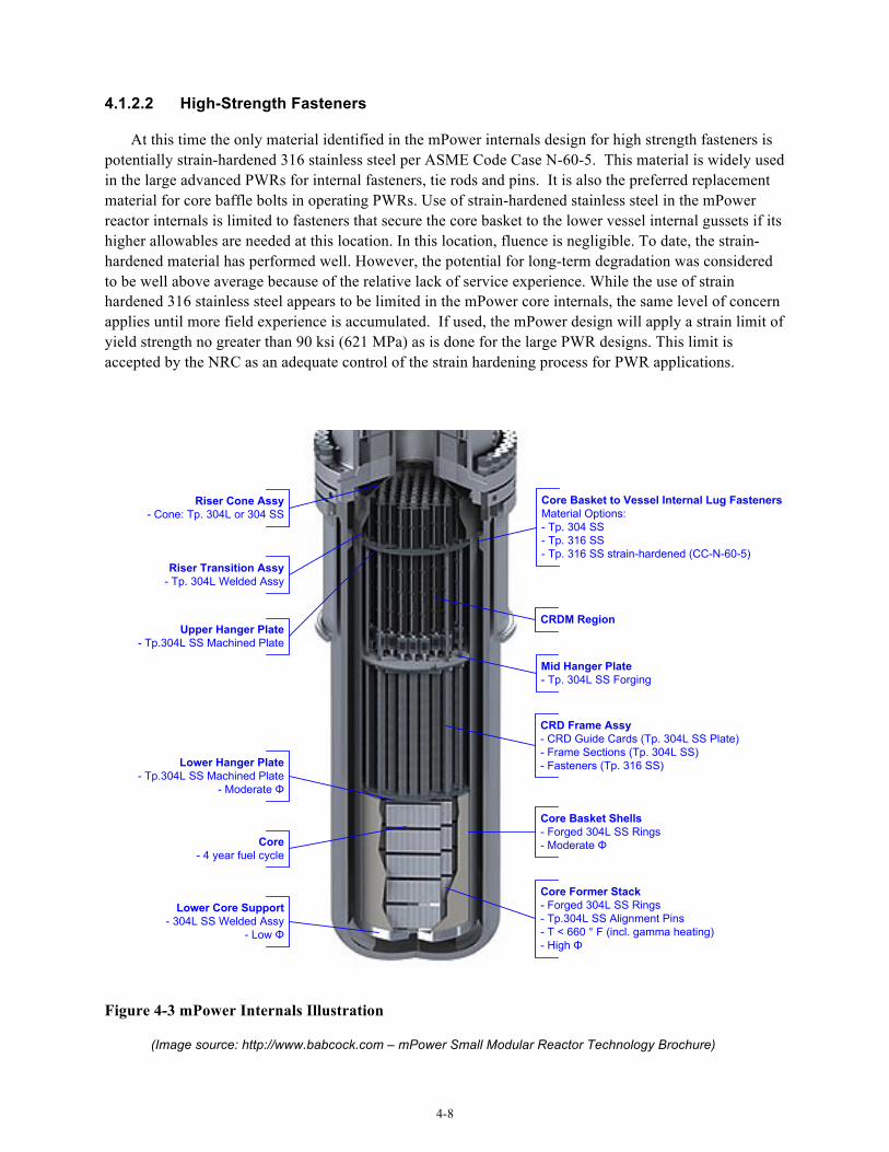
4-8
4.1.2.2 High-Strength Fasteners
At this time the only material identified in the mPower internals design for high strength fasteners is potentially strain-hardened 316 stainless steel per ASME Code Case N-60-5. This material is widely used in the large advanced PWRs for internal fasteners, tie rods and pins. It is also the preferred replacement material for core baffle bolts in operating PWRs. Use of strain-hardened stainless steel in the mPower reactor internals is limited to fasteners that secure the core basket to the lower vessel internal gussets if its higher allowables are needed at this location. In this location, fluence is negligible. To date, the strain-hardened material has performed well. However, the potential for long-term degradation was considered to be well above average because of the relative lack of service experience. While the use of strain hardened 316 stainless steel appears to be limited in the mPower core internals, the same level of concern applies until more field experience is accumulated. If used, the mPower design will apply a strain limit of yield strength no greater than 90 ksi (621 MPa) as is done for the large PWR designs. This limit is accepted by the NRC as an adequate control of the strain hardening process for PWR applications.
Core Basket to Vessel Internal Lug FastenersMaterial Options:- Tp. 304 SS- Tp. 316 SS- Tp. 316 SS strain-hardened (CC-N-60-5)
Core Former Stack- Forged 304L SS Rings- Tp.304L SS Alignment Pins- T < 660 ° F (incl. gamma heating)- High Φ
Core Basket Shells- Forged 304L SS Rings- Moderate Φ
Lower Core Support- 304L SS Welded Assy
- Low Φ
CRDM Region
Mid Hanger Plate- Tp. 304L SS Forging
Upper Hanger Plate- Tp.304L SS Machined Plate
Lower Hanger Plate- Tp.304L SS Machined Plate
- Moderate Φ
Riser Cone Assy- Cone: Tp. 304L or 304 SS
CRD Frame Assy- CRD Guide Cards (Tp. 304L SS Plate)- Frame Sections (Tp. 304L SS)- Fasteners (Tp. 316 SS)
Riser Transition Assy- Tp. 304L Welded Assy
Core- 4 year fuel cycle
Figure 4-3 mPower Internals Illustration
(Image source: http://www.babcock.com – mPower Small Modular Reactor Technology Brochure)
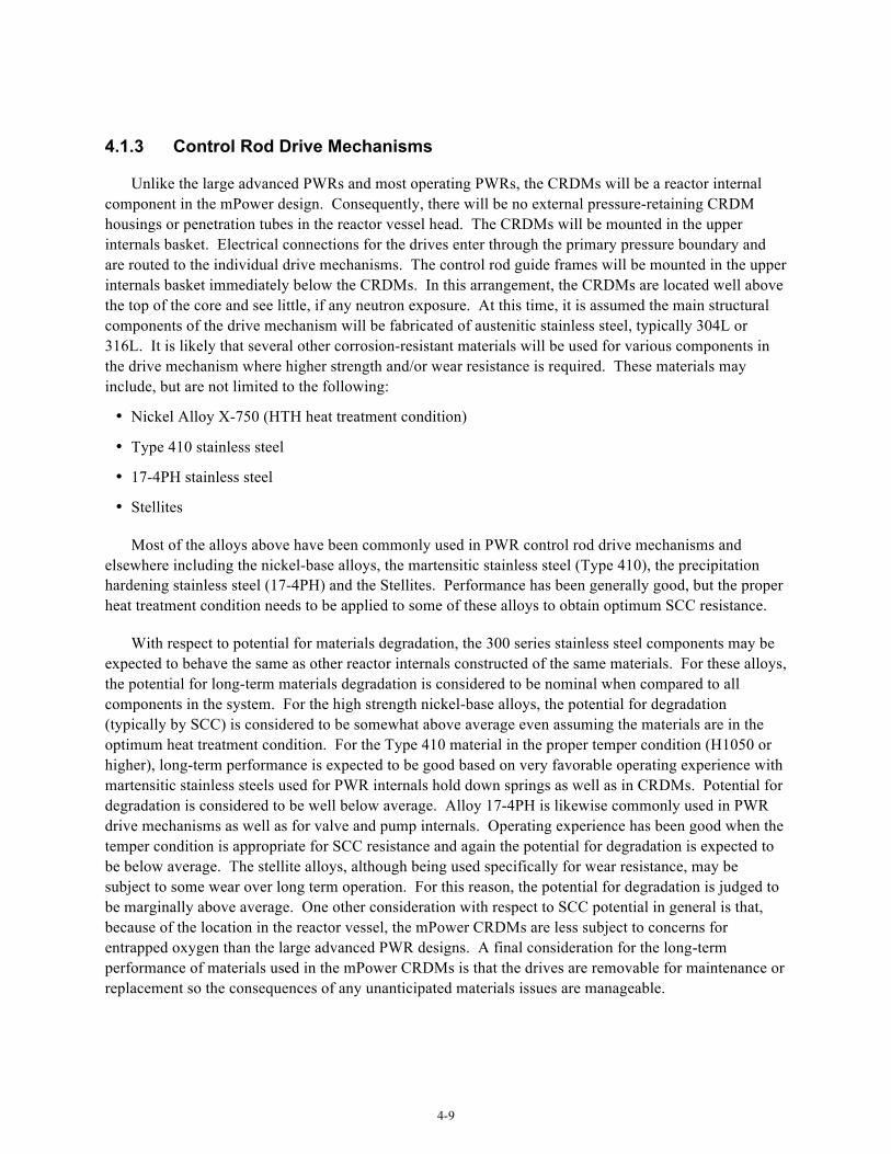
4-9
4.1.3 Control Rod Drive Mechanisms
Unlike the large advanced PWRs and most operating PWRs, the CRDMs will be a reactor internal component in the mPower design. Consequently, there will be no external pressure-retaining CRDM housings or penetration tubes in the reactor vessel head. The CRDMs will be mounted in the upper internals basket. Electrical connections for the drives enter through the primary pressure boundary and are routed to the individual drive mechanisms. The control rod guide frames will be mounted in the upper internals basket immediately below the CRDMs. In this arrangement, the CRDMs are located well above the top of the core and see little, if any neutron exposure. At this time, it is assumed the main structural components of the drive mechanism will be fabricated of austenitic stainless steel, typically 304L or 316L. It is likely that several other corrosion-resistant materials will be used for various components in the drive mechanism where higher strength and/or wear resistance is required. These materials may include, but are not limited to the following:
• Nickel Alloy X-750 (HTH heat treatment condition)
• Type 410 stainless steel
• 17-4PH stainless steel
• Stellites
Most of the alloys above have been commonly used in PWR control rod drive mechanisms and elsewhere including the nickel-base alloys, the martensitic stainless steel (Type 410), the precipitation hardening stainless steel (17-4PH) and the Stellites. Performance has been generally good, but the proper heat treatment condition needs to be applied to some of these alloys to obtain optimum SCC resistance.
With respect to potential for materials degradation, the 300 series stainless steel components may be expected to behave the same as other reactor internals constructed of the same materials. For these alloys, the potential for long-term materials degradation is considered to be nominal when compared to all components in the system. For the high strength nickel-base alloys, the potential for degradation (typically by SCC) is considered to be somewhat above average even assuming the materials are in the optimum heat treatment condition. For the Type 410 material in the proper temper condition (H1050 or higher), long-term performance is expected to be good based on very favorable operating experience with martensitic stainless steels used for PWR internals hold down springs as well as in CRDMs. Potential for degradation is considered to be well below average. Alloy 17-4PH is likewise commonly used in PWR drive mechanisms as well as for valve and pump internals. Operating experience has been good when the temper condition is appropriate for SCC resistance and again the potential for degradation is expected to be below average. The stellite alloys, although being used specifically for wear resistance, may be subject to some wear over long term operation. For this reason, the potential for degradation is judged to be marginally above average. One other consideration with respect to SCC potential in general is that, because of the location in the reactor vessel, the mPower CRDMs are less subject to concerns for entrapped oxygen than the large advanced PWR designs. A final consideration for the long-term performance of materials used in the mPower CRDMs is that the drives are removable for maintenance or replacement so the consequences of any unanticipated materials issues are manageable.
4-10
4.1.4 Steam Generator
The mPower steam generator shown in Figure 4-4 is a simple once-through design (OTSG). Alloy 690TT tubes will extend in a straight run from an upper tubesheet to the lower tubesheet. The tubes will be sealed to the tubesheet by autogenous welding and hydraulically expanded into the tubesheet. The tubes reside in an annular space between the central steam generator riser (primary pressure boundary) and the secondary shell. Feedwater nozzles and steam nozzles will be in the secondary shell with carbon steel safe ends welded to the nozzles. The nozzles and secondary shell will be fabricated from forged SA-508, Gr. 3 LAS. As typical for SG for large PWRs, the inside of the secondary shell, the nozzles and the secondary side of the tubesheets will not be clad. Between the tubes and the secondary shell is a divider plate that separates the upward feedwater flow around the tubes from the downward steam flow. The divider plate and tube spacers are fabricated of carbon steel plate (SA-516).
Since the same materials are used for the mPower steam generator as are used in all of the large advanced PWR steam generators, any concerns for long-term materials degradation are directly applicable. Therefore potential for degradation of the Alloy 690 steam generator tubes is considered to be well above average (as it is for the large advanced PWRs) compared to other primary system components due to uncertainties surrounding the lack of long exposure experience with Alloy 690 combined with ongoing concerns regarding the vulnerability of Alloy 690 to SCC in off-normal environments resulting from deposit buildup. Susceptibility to lead containing deposits is currently a significant concern in the research community. Degradation modes of concern are PWSCC, ODSCC, wear and high cycle fatigue. It is noted however, that unlike the large advanced PWR steam generators, for the mPower design there is no cold bending and stress relief of the tubes to create a U-bend configuration. This eliminates one area of potential degradation concern.
None of the large advanced PWRs (which all include recirculating steam generators) use carbon steel for spacers (aka tube support plates) because of the tube denting experience in some early design recirculating steam generators. Therefore, the mPower steam generator design represents a departure from large advanced PWRs. In recirculating steam generators, tube denting and associated cracking occurred relatively early in service life because of the buildup of carbon steel corrosion products between the spacers and the nickel-base alloy tubes. To mitigate this degradation mode, ferritic or martensitic (and some austenitic) stainless steels are used instead in the large PWRs both for advanced plant designs and replacement steam generators. Unlike operating PWRs having recirculating steam generators, mPower uses an OTSG design. To date, B&W experience with the use of carbon steel support plates in the original OTSGs of operating B&W 177-FA PWRs is reported to be good. Excessive corrosion or tube denting has not been a problem in OTSGs with carbon steel spacers with 30 years of operation. Further, the carbon steel specified for the mPower OTSG design includes a small amount of chromium to reduce rates of general corrosion and flow-accelerated corrosion (FAC). Normal specifications for SA-516 neither require nor limit Cr content.
Although B&W reports good experience with carbon steel support plates, from a perspective of long-term serviceability, there could be performance issues. Experience with long service times remains limited because many steam generators were replaced due to tubing SCC. With early life tubing SCC mitigated by Alloy 690, concerns may now extend to other potential vulnerabilities that could result in significant degradation before the end of the unit’s design life. Experience with recirculating steam generators indicates that denting of tubes at the tubesheet can occur after long service times, even though the tubesheet material is alloy steel. Should a similar phenomenon occur for the mPower design after 30 or 40 years of operation, denting could cause an adverse trend in performance before late in life. A second area
4-11
of concern could be flow-induced vibration. Broad industry experience highlights the need for improved modeling capabilities to minimize flow induced vibration (FIV) and tube wear concerns. These points are not intended to imply that the mPower steam generator may be more susceptible to degradation than advanced large PWRs. To the contrary, there are reasons to anticipate that performance will be just as good or even better considering the lower flow velocity in mPower OTSG. Rather, the primary observation is that, with regard to materials R&D to support advanced reactor designs, the mPower steam generator design is notably different than all large advanced PWRs. Ongoing or planned research focused on SCC mitigation in recirculating plants will involve evaluation of deposits, dispersants, and water chemistry refinements that may not be applicable to mPower OTSGs. Modeling and confirmatory testing programs addressing FIV vulnerabilities for large recirculating SGs will also be of limited value to the mPower design due to the substantial difference in configuration and flow pattern.
Finally, it is noted that carbon steel is used liberally for other components in the large PWR steam generators for such things as tube bundle shrouds and steam dryer components. The carbon steel divider plate in the mPower design probably falls into this category of equipment. The main degradation concern for carbon steel used for such applications is FAC in areas where fluid velocities could be significant. There is also some minor concern for general corrosion and pitting. In the mPower arrangement, it appears unlikely that the divider plate will be subjected to excessive velocities. Perceived potential for degradation of the secondary shell and nozzles is well below average as the LAS material has performed very well in this application. This conclusion applies equally to manway covers and handhold covers in the secondary shell.
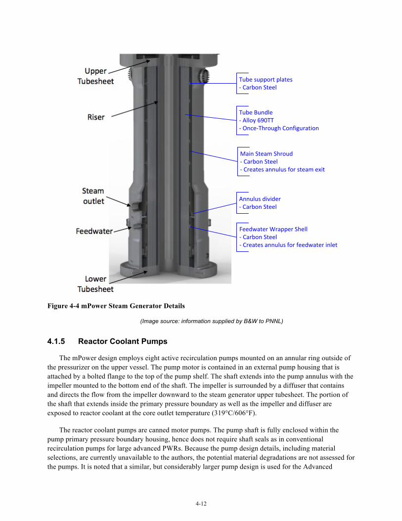
4-12
Tube support plates-‐ Carbon Steel
Main Steam Shroud-‐ Carbon Steel-‐ Creates annulus for steam exit
Feedwater Wrapper Shell-‐ Carbon Steel-‐ Creates annulus for feedwater inlet
Annulus divider-‐ Carbon Steel
Tube Bundle-‐ Alloy 690TT-‐ Once-‐Through Configuration
Figure 4-4 mPower Steam Generator Details
(Image source: information supplied by B&W to PNNL)
4.1.5 Reactor Coolant Pumps
The mPower design employs eight active recirculation pumps mounted on an annular ring outside of the pressurizer on the upper vessel. The pump motor is contained in an external pump housing that is attached by a bolted flange to the top of the pump shelf. The shaft extends into the pump annulus with the impeller mounted to the bottom end of the shaft. The impeller is surrounded by a diffuser that contains and directs the flow from the impeller downward to the steam generator upper tubesheet. The portion of the shaft that extends inside the primary pressure boundary as well as the impeller and diffuser are exposed to reactor coolant at the core outlet temperature (319°C/606°F).
The reactor coolant pumps are canned motor pumps. The pump shaft is fully enclosed within the pump primary pressure boundary housing, hence does not require shaft seals as in conventional recirculation pumps for large advanced PWRs. Because the pump design details, including material selections, are currently unavailable to the authors, the potential material degradations are not assessed for the pumps. It is noted that a similar, but considerably larger pump design is used for the Advanced

4-13
Boiling Water Reactor (ABWR). However, unlike the ABWR, for mPower the pumps are attached to the upper vessel by a bolted connection. For the ABWR the pump case is attached to the reactor vessel by a nickel alloy weld. Since there is general concern for degradation of nickel alloy welds in either BWRs or PWRs, use of a bolted connection for the mPower design would appear to represent a reduced level of risk, at least for this one aspect. This does introduce a risk factor for the high strength bolting, but it is little different from that for other external pressure boundary bolting. As discussed in Paragraph 4.1.1.3, perceived risk of degradation for this type of bolting is generally below average and main flange bolting on large advanced PWR recirculation pumps was considered to have substantially below average risk.
4.2 FMEA Comparison to Large Advanced PWRs
Tables 4-1 thru 4-4 provide a comparison of the FMEA conclusions for the mPower primary system components to the relative risk conclusions reached for large advanced PWRs (Section 3). It is important to note that on an absolute scale, there are no truly high-risk components in either large advanced PWRs or LWSMR designs in comparison with older materials and component configurations used in Gen. II reactor designs. These conclusions are presented in the context of relative risk associated with other advanced (Gen III / III+) reactor designs.
Similar to large advanced PWRs, the most significant degradation concerns in primary pressure boundary components occur for beltline shells and for Alloy 690 / 52 / 152 components. With regard to beltline shells and welds, the predicted EOL fluence will be enveloped by that estimated for large advanced PWRs, and therefore the beltline degradation concern is expected to be enveloped by the large advance PWRs. The use of high toughness LAS materials and specification of material chemistry controls substantially limits the effect of Cu and Ni embrittlement mechanisms, and may cause other embrittlement phenomena to dominate, especially for very long exposure times. However, this concern for potential development of long term embrittlement mechanisms is exactly the same as for large advanced PWRs.
Additionally, the beltline forgings will be thinner in the mPower design than occurs for other reactor designs due to a smaller vessel diameter and a lower design pressure. As a result, significant neutron fluence occurs through a greater fraction of the forging thickness. The importance of this aspect is unclear and further study may be needed to determine implications on degradation mechanisms.
For the high chromium, nickel-base materials, current vulnerabilities are similar to those described for large advanced PWRs (See Section 3). Of note for mPower is the particular application of Alloy 690/52/152. The weight of the core basket and the core are supported by a set of Alloy 690 lugs welded to the vessel ID. In large PWR designs, the weight of the core and supporting structure is carried not by a set of ID attachment lugs, but rather by the reactor vessel flange. Therefore the mPower design introduces a new core support application for Alloy 690/52/152 which is used in pressure boundary or secondary core support applications in reactor vessels of large advanced PWRs. While it is recognized the projected applied loads on this component are low, there is a particular need to ensure that the specific material processing and fabrication procedures do not introduce PWSCC vulnerability. Stress corrosion crack initiation and crack growth studies may be needed on representative materials (Alloy 690, Alloy 52/152 and weld dilution zones) to ensure that no vulnerability exists. Also, consideration may be given to surface stress mitigation by one of the various methods that have been developed for the operating PWRs.
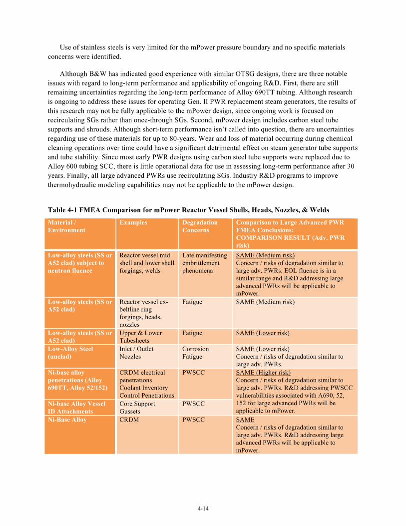
4-14
Use of stainless steels is very limited for the mPower pressure boundary and no specific materials concerns were identified.
Although B&W has indicated good experience with similar OTSG designs, there are three notable issues with regard to long-term performance and applicability of ongoing R&D. First, there are still remaining uncertainties regarding the long-term performance of Alloy 690TT tubing. Although research is ongoing to address these issues for operating Gen. II PWR replacement steam generators, the results of this research may not be fully applicable to the mPower design, since ongoing work is focused on recirculating SGs rather than once-through SGs. Second, mPower design includes carbon steel tube supports and shrouds. Although short-term performance isn’t called into question, there are uncertainties regarding use of these materials for up to 80-years. Wear and loss of material occurring during chemical cleaning operations over time could have a significant detrimental effect on steam generator tube supports and tube stability. Since most early PWR designs using carbon steel tube supports were replaced due to Alloy 600 tubing SCC, there is little operational data for use in assessing long-term performance after 30 years. Finally, all large advanced PWRs use recirculating SGs. Industry R&D programs to improve thermohydraulic modeling capabilities may not be applicable to the mPower design.
Table 4-1 FMEA Comparison for mPower Reactor Vessel Shells, Heads, Nozzles, & Welds
Material / Environment
Examples Degradation Concerns
Comparison to Large Advanced PWR FMEA Conclusions: COMPARISON RESULT (Adv. PWR risk)
Low-alloy steels (SS or A52 clad) subject to neutron fluence
Reactor vessel mid shell and lower shell forgings, welds
Late manifesting embrittlement phenomena
SAME (Medium risk) Concern / risks of degradation similar to large adv. PWRs. EOL fluence is in a similar range and R&D addressing large advanced PWRs will be applicable to mPower.
Low-alloy steels (SS or A52 clad)
Reactor vessel ex-beltline ring forgings, heads, nozzles
Fatigue SAME (Medium risk)
Low-alloy steels (SS or A52 clad)
Upper & Lower Tubesheets
Fatigue SAME (Lower risk)
Low-Alloy Steel (unclad)
Inlet / Outlet Nozzles
Corrosion Fatigue
SAME (Lower risk) Concern / risks of degradation similar to large adv. PWRs.
Ni-base alloy penetrations (Alloy 690TT, Alloy 52/152)
CRDM electrical penetrations Coolant Inventory Control Penetrations
PWSCC SAME (Higher risk) Concern / risks of degradation similar to large adv. PWRs. R&D addressing PWSCC vulnerabilities associated with A690, 52, 152 for large advanced PWRs will be applicable to mPower.
Ni-base Alloy Vessel ID Attachments
Core Support Gussets
PWSCC
Ni-Base Alloy CRDM PWSCC SAME Concern / risks of degradation similar to large adv. PWRs. R&D addressing large advanced PWRs will be applicable to mPower.
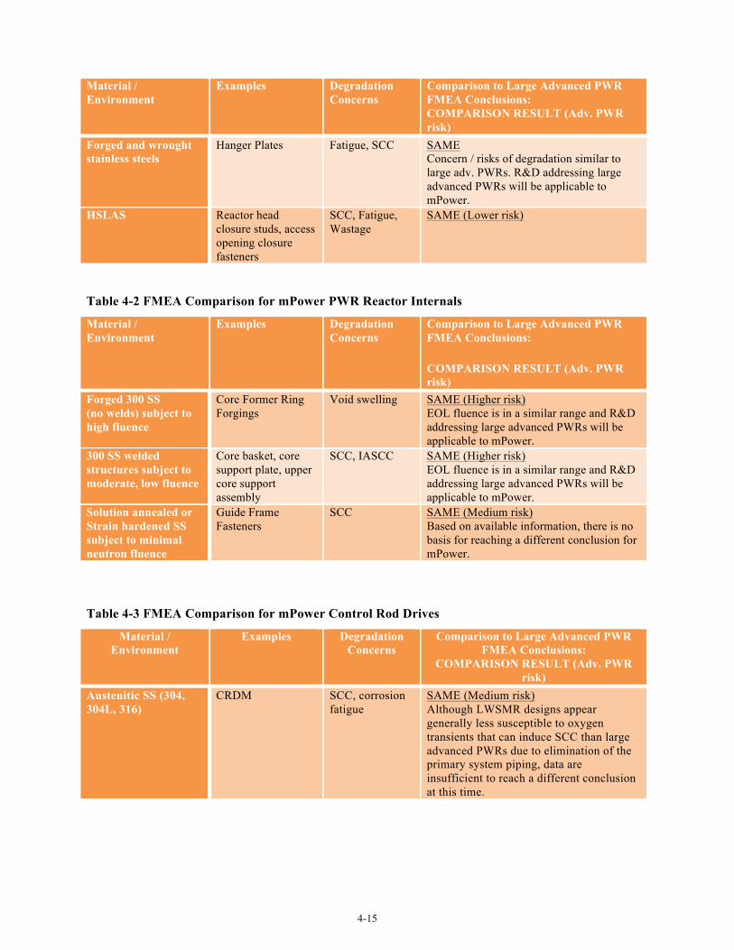
4-15
Material / Environment
Examples Degradation Concerns
Comparison to Large Advanced PWR FMEA Conclusions: COMPARISON RESULT (Adv. PWR risk)
Forged and wrought stainless steels
Hanger Plates Fatigue, SCC SAME Concern / risks of degradation similar to large adv. PWRs. R&D addressing large advanced PWRs will be applicable to mPower.
HSLAS Reactor head closure studs, access opening closure fasteners
SCC, Fatigue, Wastage
SAME (Lower risk)
Table 4-2 FMEA Comparison for mPower PWR Reactor Internals
Material / Environment
Examples Degradation Concerns
Comparison to Large Advanced PWR FMEA Conclusions:
COMPARISON RESULT (Adv. PWR risk)
Forged 300 SS (no welds) subject to high fluence
Core Former Ring Forgings
Void swelling SAME (Higher risk) EOL fluence is in a similar range and R&D addressing large advanced PWRs will be applicable to mPower.
300 SS welded structures subject to moderate, low fluence
Core basket, core support plate, upper core support assembly
SCC, IASCC SAME (Higher risk) EOL fluence is in a similar range and R&D addressing large advanced PWRs will be applicable to mPower.
Solution annealed or Strain hardened SS subject to minimal neutron fluence
Guide Frame Fasteners
SCC SAME (Medium risk) Based on available information, there is no basis for reaching a different conclusion for mPower.
Table 4-3 FMEA Comparison for mPower Control Rod Drives
Material / Environment
Examples Degradation Concerns
Comparison to Large Advanced PWR FMEA Conclusions:
COMPARISON RESULT (Adv. PWR risk)
Austenitic SS (304, 304L, 316)
CRDM SCC, corrosion fatigue
SAME (Medium risk) Although LWSMR designs appear generally less susceptible to oxygen transients that can induce SCC than large advanced PWRs due to elimination of the primary system piping, data are insufficient to reach a different conclusion at this time.
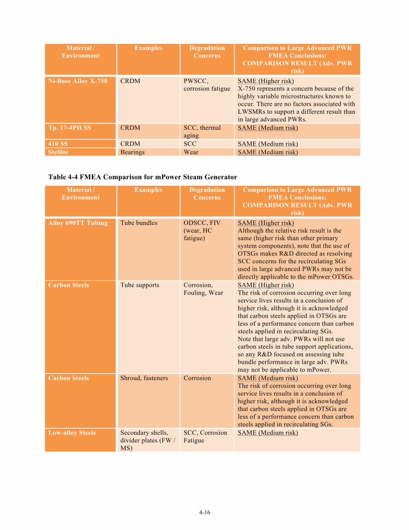
4-16
Material / Environment
Examples Degradation Concerns
Comparison to Large Advanced PWR FMEA Conclusions:
COMPARISON RESULT (Adv. PWR risk)
Ni-Base Alloy X-750 CRDM PWSCC, corrosion fatigue
SAME (Higher risk) X-750 represents a concern because of the highly variable microstructures known to occur. There are no factors associated with LWSMRs to support a different result than in large advanced PWRs.
Tp. 17-4PH SS CRDM SCC, thermal aging
SAME (Medium risk)
410 SS CRDM SCC SAME (Medium risk) Stellite Bearings Wear SAME (Medium risk)
Table 4-4 FMEA Comparison for mPower Steam Generator
Material / Environment
Examples Degradation Concerns
Comparison to Large Advanced PWR FMEA Conclusions:
COMPARISON RESULT (Adv. PWR risk)
Alloy 690TT Tubing Tube bundles ODSCC, FIV (wear, HC fatigue)
SAME (Higher risk) Although the relative risk result is the same (higher risk than other primary system components), note that the use of OTSGs makes R&D directed as resolving SCC concerns for the recirculating SGs used in large advanced PWRs may not be directly applicable to the mPower OTSGs.
Carbon Steels Tube supports Corrosion, Fouling, Wear
SAME (Higher risk) The risk of corrosion occurring over long service lives results in a conclusion of higher risk, although it is acknowledged that carbon steels applied in OTSGs are less of a performance concern than carbon steels applied in recirculating SGs. Note that large adv. PWRs will not use carbon steels in tube support applications, so any R&D focused on assessing tube bundle performance in large adv. PWRs may not be applicable to mPower.
Carbon Steels Shroud, fasteners Corrosion SAME (Medium risk) The risk of corrosion occurring over long service lives results in a conclusion of higher risk, although it is acknowledged that carbon steels applied in OTSGs are less of a performance concern than carbon steels applied in recirculating SGs.
Low-alloy Steels Secondary shells, divider plates (FW / MS)
SCC, Corrosion Fatigue
SAME (Medium risk)
5-17
5.0 Evaluation of NuScale Reactor This section provides a preliminary assessment of materials issues and R&D needs for the NuScale
reactor which is still under active design at the time this report was prepared. Consequently, the design configurations and materials selections shown in this report are subject to changes as the design evolves. In addition, a number of aspects related to the design were judged to be proprietary and are not included in this evaluation. The approach and conclusions reached in this section are built on the evaluation of large advanced PWRs from Section 3. Although there are some fundamental differences between the NuScale design configuration and that of traditional PWRs, from the perspective of materials selection, fabrication practices and environmental exposure, the NuScale design has many similarities with large advanced PWRs. Where there are significant differences, these are highlighted in the discussion.
5.1 Component Descriptions and General Discussion
The NuScale design retains most of the functional components of large PWR designs and uses an integrated vessel concept that is broadly similar to other LWSMRs. The overall assembly of the NuScale reactor primary/secondary system is illustrated in Figure 5-1.
The primary pressure boundary includes a reactor pressure vessel, pressurizer and steam generator. The reactor vessel houses reactor internals and control rods. Control rod drive and rod travel housings are mounted to the top head of the reactor vessel which houses the integral pressurizer dome. However, there are a number of elements that set the NuScale design apart from advanced large PWRs. These include:
• Passive primary system operation: All prior PWR designs include primary system pumps. Although some designs have been termed “passive”, this refers to emergency safety system design, such that the reactor can be safely shutdown without the need for safety system pumps. In the case of the NuScale reactor design, natural convection provides the driving force for primary coolant flow through the reactor vessel. NuScale estimates that primary system fluid velocities will be relatively low (~ 1 m/s).
• Helical coil steam generator: Primary to secondary heat transfer is accomplished via a helical coil steam generator having two independent sets of coils. Notably, primary coolant flow occurs on the tubing OD and secondary-side flow / steam generation occurs on the coil tube ID.
• Adaptation of control rods to include “extensions” that span the considerable distance from the vessel upper dome to the core region.
• Wetted containment vessel design: The containment vessel is submerged in a large pool of water, termed the containment cooling pool. This large volume of water functions as the ultimate heat sink for the design.
Although there are significant differences in primary system design, the approach toward primary system component materials selection and fabrication is similar to other LWSMR designs. The vessel design involves a relatively tall and narrow primary pressure vessel constructed from forged LAS rings that are clad with stainless steel. The vessel includes three principle regions, a lower region that houses the core and control rods, a mid-region that containing the steam generator, and an upper plenum that
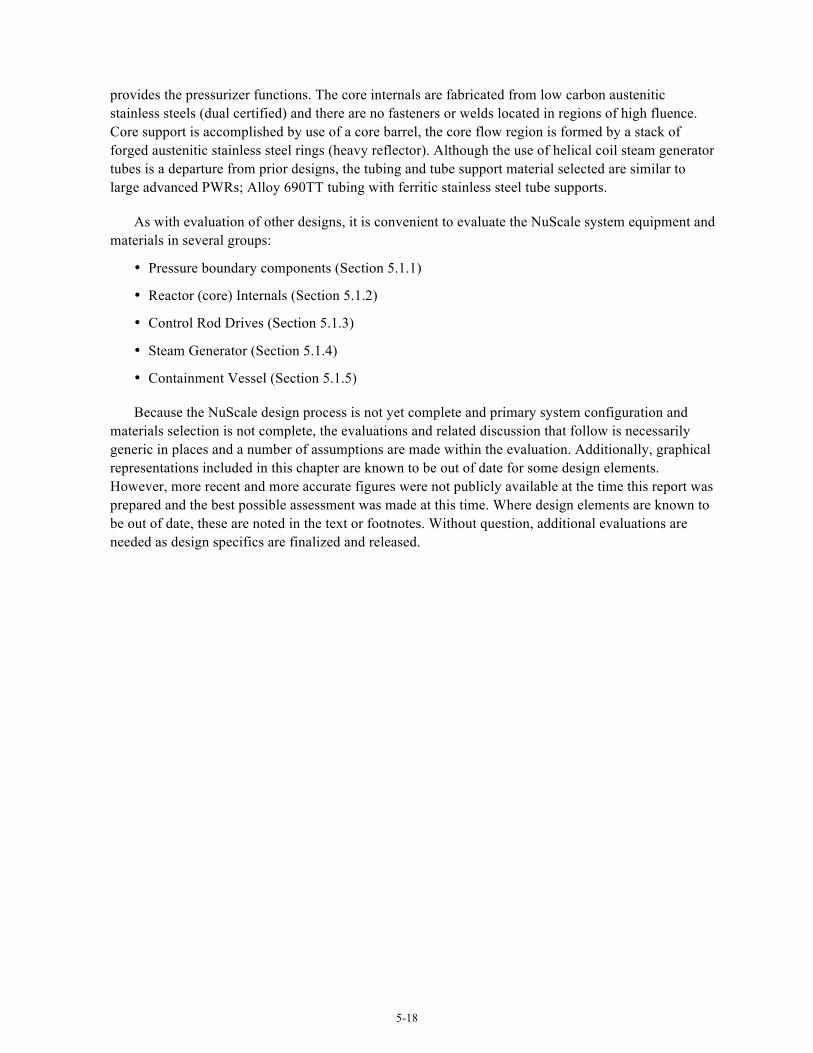
5-18
provides the pressurizer functions. The core internals are fabricated from low carbon austenitic stainless steels (dual certified) and there are no fasteners or welds located in regions of high fluence. Core support is accomplished by use of a core barrel, the core flow region is formed by a stack of forged austenitic stainless steel rings (heavy reflector). Although the use of helical coil steam generator tubes is a departure from prior designs, the tubing and tube support material selected are similar to large advanced PWRs; Alloy 690TT tubing with ferritic stainless steel tube supports.
As with evaluation of other designs, it is convenient to evaluate the NuScale system equipment and materials in several groups:
• Pressure boundary components (Section 5.1.1)
• Reactor (core) Internals (Section 5.1.2)
• Control Rod Drives (Section 5.1.3)
• Steam Generator (Section 5.1.4)
• Containment Vessel (Section 5.1.5)
Because the NuScale design process is not yet complete and primary system configuration and materials selection is not complete, the evaluations and related discussion that follow is necessarily generic in places and a number of assumptions are made within the evaluation. Additionally, graphical representations included in this chapter are known to be out of date for some design elements. However, more recent and more accurate figures were not publicly available at the time this report was prepared and the best possible assessment was made at this time. Where design elements are known to be out of date, these are noted in the text or footnotes. Without question, additional evaluations are needed as design specifics are finalized and released.
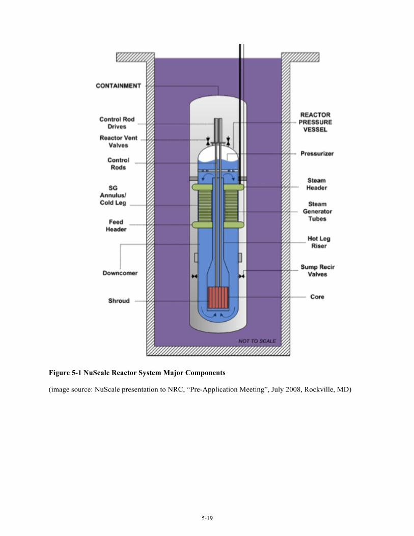
5-19
Figure 5-1 NuScale Reactor System Major Components
(image source: NuScale presentation to NRC, “Pre-Application Meeting”, July 2008, Rockville, MD)
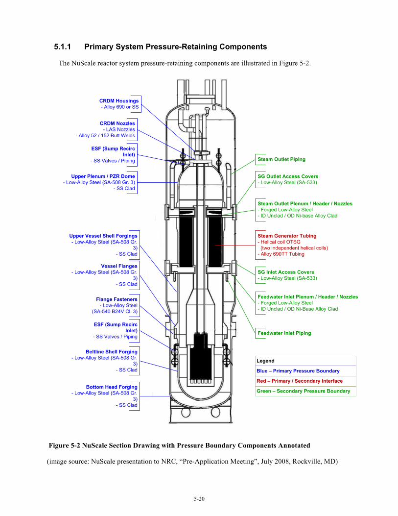
5-20
5.1.1 Primary System Pressure-Retaining Components
The NuScale reactor system pressure-retaining components are illustrated in Figure 5-2.
Beltline Shell Forging- Low-Alloy Steel (SA-508 Gr.
3)- SS Clad
Bottom Head Forging- Low-Alloy Steel (SA-508 Gr.
3)- SS Clad
Upper Plenum / PZR Dome- Low-Alloy Steel (SA-508 Gr. 3)
- SS Clad
Steam Generator Tubing- Helical coil OTSG (two independent helical coils)- Alloy 690TT Tubing
CRDM Nozzles- LAS Nozzles
- Alloy 52 / 152 Butt Welds
Legend
Blue – Primary Pressure Boundary
Red – Primary / Secondary Interface
Green – Secondary Pressure Boundary
ESF (Sump Recirc Inlet)
- SS Valves / Piping
Vessel Flanges- Low-Alloy Steel (SA-508 Gr.
3)- SS Clad
Upper Vessel Shell Forgings- Low-Alloy Steel (SA-508 Gr.
3)- SS Clad
ESF (Sump Recirc Inlet)
- SS Valves / Piping
Steam Outlet Plenum / Header / Nozzles- Forged Low-Alloy Steel- ID Unclad / OD Ni-base Alloy Clad
Feedwater Inlet Plenum / Header / Nozzles- Forged Low-Alloy Steel- ID Unclad / OD Ni-Base Alloy Clad
SG Inlet Access Covers- Low-Alloy Steel (SA-533)
CRDM Housings- Alloy 690 or SS
SG Outlet Access Covers- Low-Alloy Steel (SA-533)
Flange Fasteners - Low-Alloy Steel
(SA-540 B24V Cl. 3)
Steam Outlet Piping
Feedwater Inlet Piping
Figure 5-2 NuScale Section Drawing with Pressure Boundary Components Annotated
(image source: NuScale presentation to NRC, “Pre-Application Meeting”, July 2008, Rockville, MD)
5-21
5.1.1.1 Pressure Vessel Shells, Heads, Flanges, Nozzles and Welds
The NuScale reactor vessel includes two major sections with a flange connection located near the bottom of the vessel, above the top of the core region. The lower vessel section houses the core and core supports and includes one or more beltline shell forgings and a lower head. The upper vessel houses the integral steam generator, the pressurizer and contains several shell ring forgings, feedwater and main steam headers / nozzles, and access openings. Primary pressure boundary components include the lower vessel shell and bottom head, flanges, upper vessel shells and upper plenum (pressurizer) dome, and the upper and lower steam generator plenums. The material of construction for the vessel LAS components is SA-508, Grade 3, Class 1 or 2. Assuming the design is consistent with other advanced PWRs, manway covers, handhold covers and inspection port covers are fabricated of SA-533, type B LAS plate. In the NuScale design, not only are the reactor vessel ID surfaces clad (with stainless steel or nickel-base stainless alloy), the OD surfaces are also clad (with nickel-base stainless alloy). This is necessary to facilitate refueling activities, which entail flooding the annulus space between the reactor vessel and containment vessel.
Components that are not exclusively primary system pressure boundary include the steam generator upper and lower plenums, which are an interface between the primary and secondary systems, and the feedwater and main steam nozzles / headers. For both feedwater inlet and main steam outlets, the vessel contains four inlet nozzles connected to headers that provide flowpaths to the steam generator plenums. Although details regarding this configuration are limited, these headers are assumed to be LAS construction. Within the vessel enclosure, the outer surface of these headers is primary pressure boundary with secondary-side fluid on the header inner surface. Each header has a flanged access for steam generator tube inspection and maintenance.
These materials are the same as used for large advanced PWR designs, so given similar water chemistry and operating temperatures, materials degradation concerns are very similar. In general, clad LASs rank below average with respect to risk of long-term materials degradation. The exception is the core beltline shell ring.
The NuScale reactor vessel beltline shell ring is forged LAS, which is the same as for all the large advanced PWRs. Although details regarding material chemistry for the beltline shell and adjacent welds are not available, modern controls on material chemistry to limit embrittlement by neutron irradiation and ensure a low initial RTNDT can be assumed. The estimated 60 year fluence for the NuScale design is similar to estimates for large PWRs. Therefore, the overall risk of material degradation is considered to be similar to large advanced PWRs, somewhat above average compared with other primary system components, but not dramatically so. One difference of note is the relatively thinner vessel thickness compared with large PWRs. The smaller diameter and lower pressure allow for a significantly thinner vessel. Thinner forgings will result in better initial fracture toughness properties. However, thinner vessels also result in a higher neutron dose at the vessel 3/4T and OD locations. This is noted in the context of being different than a large PWR. It is not presently clear if there are any implications of this condition on long-term degradation risk.
The only vessel ID attachments specifically indicated by NuScale in the design are two sets of stabilizing lugs, one located at the upper end of the reactor internals assembly at the vessel flange and a second set near the bottom of the internals core support assembly. These lugs are described by NuScale as “bumpers” that function only to restrain lateral motion. In the current design, these lugs will be fabricated from LAS (clad with stainless steel or nickel-base stainless alloy). Although not specifically
5-22
confirmed by NuScale, a set of attachment pads are assumed to exist in the vessel bottom head region since they indicated that the reactor internals will be supported from the bottom head and not the vessel flange.6 Material selection and joint configuration details for these support lugs were not available at the time this report was prepared.
5.1.1.2 Austenitic Pressure-Retaining Penetrations, Nozzles, Safe Ends and Piping Components
Since there are no large external piping connections to the primary pressure boundary components, use of austenitic alloys for pressure boundary components is limited in comparison with large PWR designs. The NuScale design does include 16 upper head penetrations for CRD access. However instead of a penetration tube with J-groove weld configuration, the NuScale design uses LAS nozzles integrally forged/machined into the vessel upper head. The transition to the low carbon stainless steel CRD housing is accomplished by Alloy 52/152 dissimilar metal butt welds. Information provided by NuScale also indicates the use of Ni-Cr-Fe “safe ends,” presumed to be Alloy 690, which are welded between the LAS nozzle stubs and the stainless steel CRD housings. The upper head region also includes LAS vent valve nozzles, described as having a configuration similar to the CRD nozzles. Lower in the reactor vessel, there are connections for reactor coolant recirculation and cleanup and for emergency inlet valves. For these primary system connections, the nozzles likely will be separate LAS forgings, rather than integrally forged into the vessel shell. Otherwise, the nozzle configuration will be similar to the upper head penetrations with Alloy 52/152 dissimilar metal butt welds, Ni-Cr-Fe safe ends and a transition to stainless steel piping.
Consistent with conclusions reached for other advanced PWR designs, some increased risk of degradation is judged to exist for Alloy 690/52/152 locations based on remaining uncertainties regarding long-term performance. However, the NuScale CRD nozzle design does merit some additional discussion. The use of CRDs that penetrate the pressurizer upper head results in exposure of Alloy 690/52/152 to a higher service temperature than occurs for large advanced PWRs (Tcold vessel head designs, with resulting CRDM penetration operating temperatures around 540°F). The NuScale pressurizer temperature is approximately 630°F. Given the temperature dependence of PWSCC that occurs for Alloy 600 and cold-worked Alloy 690 materials, exposure at pressurizer temperatures does result in some increased risk of degradation. The use of Alloy 690 safe ends represents an additional uncertainty because some laboratory testing has shown PWSCC growth rates of concern for selected material conditions. Additionally, this design configuration seems to require an additional set of Alloy 52/152 dissimilar metal welds (i.e., both LAS nozzle to Alloy 690 safe end welds and Alloy 690 safe end to the stainless steel housing welds). However, this increased risk is potentially offset to some extent by the elimination of penetration tube and j-groove weld design. In operating plants, nozzle design using penetration tubes and j-groove welds has been a significant factor for many PWR primary system SCC occurrences where high residual stresses and strains occur at the weld to penetration tube interface. Although use of higher Cr materials significantly mitigates the PWSCC concerns, the exclusive use of butt welded configurations simplifies the weld joint and likely will result in fewer weld repairs, a more favorable distribution of residual stresse, and improved inspectability (since the joint design eliminates the need to perform in-service examinations using surface techniques).
6 Note that Figure 5-1 and 5-2 show an older design configuration concept where the reactor vessel internals were supported at the vessel flange.
5-23
Apart from cladding of LAS surfaces exposed to primary coolant, use of austenitic stainless steels in the NuScale vessel design appears to be limited. Applications likely include CRD pressure housings, vent and recirculation valves and attached piping (very short piping runs), feedwater piping, main steam piping, and small diameter instrumentation lines. NuScale plans to specify austenitic stainless steels as low carbon with dual certification, an approach used successfully in the past for BWR designs. Stainless steel weld metal will also be low carbon with ferrite content controlled to a limited range. Austenitic stainless steels have performed well in primary water service unless subject to significant cold work or exposed to oxidizing conditions. In addressing oxidizing conditions, there is potentially some increased risk of SCC associated with the stainless steel CRD housings located in the upper head region. In traditional PWR designs, this area is known to be at risk for oxygen entrapment and special procedures are implemented to ensure oxidizing conditions do not occur. The NuScale design introduces a unique issue in that these housings are exposed to the pressurizer steam space, an area that tends to collect non-condensable gases, including oxygen. The design suggests that oxygen removal issues may be different than for large advanced PWR designs. This concern is mitigated by the use of low carbon stainless steel, but data on operation at pressurizer temperatures is limited.
Austenitic stainless steels components planned in feedwater and main steam applications are worthy of note. Although stainless steels are used in some secondary-side pressure boundary applications in other advanced PWRs, the main process piping components are consistently carbon steel or LAS. In the NuScale design, use of austenitic stainless steel in this application results from the same refueling flood-up process that causes the reactor vessel OD to require stainless steel clad. Exposure to the high temperature feedwater inlet and main steam outlet flows introduces the potential for SCC. However, SCC has not been a significant problem for stainless steels exposed to similar environments in Gen. II reactors and use of low carbon materials provides additional margin particularly if oxidizing conditions are possible. As a result, a significant change to the risk assessment doesn’t appear warranted to address this effect alone. Another issue that would seem to be relevant is secondary-side SCC. Repeated exposure to borated water during each refueling flood up, followed by drying and high-temperature exposure at unit startup, could concentrate contaminants on the OD surfaces. Such a condition could potentially lead to SCC in austenitic stainless steel. Some further investigation of this observation may be required to determine if this is a genuine concern. Given that the transient coolant exposure conditions aren’t well defined by the available information, some consideration of the long-term performance risks for these piping components would seem reasonable.
5.1.1.3 Pressure-Retaining Bolting
The NuScale reactor vessel main closure bolting is fabricated from SA-540 Grade B24V Class 3 LAS. The measured maximum yield strength of the bolting material will be limited 150 ksi as required in Reg. Guide 1.65. This high strength LAS is used in similar pressure boundary applications by the large advanced PWR designs. Bolting for smaller flanged closures (e.g., access covers and inspection ports on both the primary and secondary side) was not specified by NuScale. However if applied in a non-wetted location, it is reasonable to assume that SA-193, Grade B7 will be used. Since the bolting materials are the same as for the large PWRs, the discussion of potential degradation concerns in Section 3.1 applies and the potential for long-term materials degradation is judged to be similar to the large advanced PWRs. The potential for degradation is low in comparison with other primary system components. At this time, the only high-strength corrosion resistant alloy specified for use as primary system pressure retaining bolting is 17-4PH. Where specified with a limit on hardness, SCC performance has been good. One notable condition applicable only to the NuScale design is the
5-24
periodic submergence that will occur due to the need to flood the annulus between the reactor vessel and containment vessel for refueling. Some additional risk of SCC would seem reasonable given the exposure to a wet/dry cycle at each refueling interval.
5.1.2 Reactor Internals
The NuScale core support system includes a core barrel and a stacked solid stainless steel neutron reflector that forms the core outline, improves neutron economy, and provides some neutron shielding to the core barrel and reactor vessel shell. Core support of reactor internals is achieved by a core support cylinder mounted on the bottom of the reactor vessel head. Horizontal restraints located at the RPV flange provide for lateral restraint. This design is different from large advanced PWRs as vertical loads are transmitted through the RPV bottom head as opposed to the RPV closure flange. Horizontal restraints located at the bottom as well as at the RPV flange ensure high seismic resistance of the core support structures and minimizes seismic and other dynamic loading on the fuel assemblies. This alternate core support configuration does not conceptually introduce any new or different material performance concerns. Importantly, this configuration would eliminate the need for a high-strength compression ring type spring at the vessel flange, a simplification that eliminates any concerns regarding long-term suitability of the martensitic stainless steels typically used.
Above the core support structure, additional structures exist to house, guide and support the neutron absorbing control rods and control rod extensions that connect the control rods themselves to the CRDMs located above the vessel top dome. Above the control rod guide assembly is a partial cone that reduces the flow area exiting the core into a riser cylinder that functions as a hot leg, directing core outlet flow vertically upward through the center region of the vessel to an area just below the pressurizer region. Since this design is pumped by natural circulation, this central riser is in effect a chimney that passes through the center of the helical coil steam generator. At the top of the riser chimney, the core flow is directed radially outward, then downward through the steam generator section.
5.1.2.1 Structures & Welds
Although detailed information regarding the reactor internals structures is not available, it is known that NuScale intends to fabricate most of the reactor internals structures from low carbon, dual certified austenitic stainless steels (Type 304/304L). Although specific values are not available, the carbon content and ferrite level of weld metal will be controlled. The primary degradation concern associated with welded stainless steel reactor internals structures in the unirradiated or moderately irradiated condition is SCC. This concern would be enhanced in the event of off-normal water chemistry (e.g. oxygen intrusion or trapped oxygen in stagnant regions) and/or excessive cold work introduced in fabrication. For the NuScale design, an evaluation of material performance risks is difficult with limited information on materials or fabrication methods defined. Assuming no special attention during fabrication to minimize cold work, a somewhat elevated risk of SCC may exist. However, this concern is likely offset by a configuration that offers little opportunity for regions of entrapped oxygen. The potential in this design for other off-normal water chemistry transients is not presently apparent. Although not confirmed, final NuScale material controls are expected for stainless steel strength levels and on ferrite content in the stainless steel weld metals similar to those for the advanced PWRs.
5-25
For the highly irradiated internals (core former rings and the core barrel), the concerns for long-term material performance are similar to those for the large PWRs, i.e. void swelling, IASCC and embrittlement. Highly irradiated internals were considered to have well above average potential for degradation in the large PWRs. Given the peak fluence estimate at the reactor vessel wall for the NuScale design, it can be assumed that the core former (reflector assembly) will be well over the threshold fluence for void swelling and IASCC at least in some locations. Irradiation embrittlement and the associated loss of toughness are certain. However since it is currently assumed the NuScale core former is assembled from stacked rings without cold forming or welding, the concern for IASCC is somewhat reduced as it is for the large units that employ this type of core former design. There remains some uncertainty with respect to potential for void swelling and how it may affect the stacked ring design. The reflector assembly will include flow passageways, allowing for bypass of some core flow through the reflector, but gamma heating within the reflector is anticipated. A preliminary estimate of gamma heating in the core former suggests that peak temperatures will be around 650°F. If peak temperatures are significantly higher than 650°F, swelling will be a definite concern. Mitigating this issue is that the reflector assembly design is under a very low stress state and allows for free expansion if swelling occurs. Further complicating the evaluation is that NuScale has indicated that some thought is being given to alternate neutron reflector materials with the objective of improving neutron economy. As the alternative materials were not specifically identified, no additional review and evaluation can be performed.
Current core barrel fabrication is by cold rolling and welding stainless steel plate material. While this is similar construction to the large PWR design, the cold work effects on thinner plate rolled to a significantly smaller radius may be different. While the thinner material may offset the tighter bend radius, the overall effects on bulk and surface cold work are not immediately apparent. Welding will likely introduce residual stresses sufficient to promote IASCC. However, the reflector provides some neutron shielding so dose to the core barrel is limited compared to designs that use a more conventional core shroud. NuScale indicates that the core barrel may be fabricated of forged rings to offset the potential negative effects of cold working and weld residual stress on IASCC resistance if necessary.
5.1.2.2 High-Strength Fasteners
At the current level of design detail, no specifics regarding reactor internals fastener application are known. NuScale has indicated that where high strength fasteners are needed, the material of choice is likely to be strain-hardened 316, presumably consistent with ASME Code Case N-60-5 or -6. This material is widely used in the large advanced PWRs for internal fasteners, tie rods, and pins. It is also the preferred replacement material for core baffle bolts in operating PWRs. Conventionally, the amount of cold work introduced is controlled to keep the room temperature yield strength below 90 ksi. This is a limit preferred by the NRC and appears in the licensing documents for the large advanced PWRs. To date, strain-hardened 316 has performed well in PWR service. However because of the relative lack of experience, the potential for long-term degradation was considered to be above average for the large advanced PWR designs. While the use of this material in reactor internals will likely be limited in the NuScale design and specific locations relative to the active fuel are unknown, a similar level of concern applies until more field experience is accumulated. There is an additional caution in this case in that NuScale’s limit for strain-hardened 316 is 20% maximum cold work. Publically available data suggest that 20% cold work in Type 316 will result in room temperature yield strength of about 98 ksi which is slightly above the 90 ksi limit preferred by the NRC and applied by the large advanced PWRs.
5-26
5.1.3 Control Rod Drives
No information is available at this time regarding the materials of construction for the CRD housings and mechanisms. Making an assumption that the materials of construction are similar to other reactor designs, materials in use could include austenitic stainless steels, Type 410 martensitic stainless steel and Alloy 690 along with various higher-strength materials such as nitrogen strengthened austenitic stainless steels (XM-19), nickel-base alloys (Alloy 718 and Alloy X-750), and precipitation hardened martensitic stainless steel (17-4PH).
As discussed for other designs, performance of materials typically selected for CRDs has been historically good. For the NuScale design, the lack of any materials information prevents any meaningful assessment of material-specific performance. However, the unique design configuration used by the NuScale design does merit brief discussion. As summarized in Section 5.1.1 above with regard to pressure retaining components, the use of CRDs that penetrate the pressurizer upper head results in exposure to a higher service temperature than for other LWR designs. Large advanced PWRs include Tcold vessel head designs, with resulting CRDM penetration operating temperatures around 550 °F. The NuScale pressurizer temperature is expected to be 630°F. Depending on material selection, this higher operating temperature could substantially increase thermal embrittlement rates for susceptible materials (e.g., Type 17-4PH stainless steel) or increase the risk of PWSCC initiation for nickel-base alloys (e.g., Alloy X-750 and Alloy 690). Therefore, evaluation of the NuScale design generically introduces some additional risk of degradation due to the uncertainty of operating CRD materials at a higher service temperature.
Finally, some uncertainties appear to exist regarding the CRD configuration. In the NuScale design, the rods attaching the neutron absorbing section to the drives located above the vessel are considerably longer than in other PWR designs. This occurs because of the added height of the steam generator and pressurizer sections that the rods must travel through. Although the NuScale design primary-side fluid velocities are known to be relatively low, unanticipated flow-induced effects occurring in PWR upper plenum components and BWR steam dryers illustrate the complexities involved. Even in regions of relatively low fluid velocity and turbulence, significant wear has occurred at a few operating plants.
5.1.4 Steam Generator
NuScale employs a once-through, vertical helical coil steam generator design. With this design, feedwater enters into a lower integrated tubesheet plenum (ITP), flows upward through the tube bundle where it is converted to steam that exits through the upper ITP. One significant difference from a standard once-through design is that the secondary fluid (feedwater/steam) flows through the inside diameter (ID) of the tubes and primary water flows on the outside diameter (OD).
Figure 5-3 is an illustration of flowpaths for the helical coil design provided for the purpose of general illustration only. In this illustration, the center element (18) is the riser. The riser is described in the reactor internals section above as a structure that functions as a hot leg, directing core outlet flow upward through the center region of the vessel where the core flow is directed radially outward, then downward through the steam generator section. The lower integrated tubesheet / plenum (ITP) directs feedwater flow through into the tube bundles (at 20A & 20B). The tube bundles represented by items 23 & 24 carry fluid to the upper ITP. Current plans include two independent tube bundles. Feedwater

5-27
and steam flows may be independently controlled to the independent bundles to allow for continued operation in the event of a failure of a tube in one of the steam generator bundles.
Figure 5-3 Helical Coil Heat Exchanger Example
(Image source: US Patent Application 2012/0111287)
5-28
NuScale indicates that tubes will be hydraulically expanded into the tubesheet, although the specific details of this design do not appear to be finalized. The tubesheet connection is likely to be significantly thinner than prior designs and would need either to be clad with an austenitic material such as Alloy 52 or constructed from an Alloy 690 plate or forging. In addition, evaluation remains in progress to determine if connecting welds can be seal welds only or if the welds must have a structural function. Regardless of the specific configuration, the tube to tubesheet design configuration will be different in some respects from traditional tube to tubesheet connections. If a low-alloy tubesheet is used, then the tubesheet must be clad on the tube side, since primary water containing boric acid flows on the OD of the tubes. If the tubesheets are fabricated from Alloy 690 plate or forgings, this will be a relatively new application of Alloy 690 in a LWR. An additional configuration detail of note is the need to install flow orifices at in the tube inlets for the purpose of precluding density wave flow oscillations within the tubes. These orifices must be removable to facilitate inspection from the inlet end of the tubes.
Notably, the risk of PWSCC within the steam generator should be somewhat reduced in comparison with large advanced PWRs. Operating temperatures associated with the NuScale design are lower; Thot for the NuScale design is approximately 590°F, compared with hot leg temperatures at or above 600°F for all Gen. II and advanced PWR designs. Additionally, the large radius of curvature of the helical coil reduces the potential for high fabrication-induced stresses, as can occur at recirculating steam generator U-bends. However, it has not yet been determined if the helical coil bends will be heat treated after forming. Consequently, the amount of cold strain in the thermally treated Alloy 690 tubes will need to be considered relative to existing data on PWSCC growth rates in cold worked material. Given the relatively large radius of the coils, this is not expected to be a concern.
The major concern of alloy 690 SCC in secondary water due to concentrated impurities (lead in particular) should also be reduced since line-contact crevices are eliminated on the tube ID. There have been some issues in advanced gas-cooled reactor steam generators where secondary water is boiled into steam and superheated on the tube ID with a tendency for fouling and concentration of impurities in the boiling crisis zone. It is important to note that the NuScale steam generator is expected to operate quite differently. More detailed analysis is recommended for the SCC potential in the alloy 690 tubing as the steam generator design evolves further.
Materials of construction for the tube supports have not yet been finalized, but will likely be Type 405 stainless steel. Selection of materials for this application introduces a significant new application of ferritic stainless steel as a passive, long-lived structure within the primary system. Type 405 stainless steel has been used extensively in secondary-side tube support applications, but not in the primary system. Although the application does not raise any significant degradation concerns, some investigation to ensure no vulnerabilities exist seems reasonable.
To summarize the steam generator evaluation, no specific materials performance concerns were identified. However, the NuScale steam generator design differs significantly from the recirculating or straight tube once-through designs used for PWRs. As a result, research focused on mitigating SCC risk in large advanced PWRs will not be relevant to the NuScale design. There may also be unique considerations associated with the tube-to-tubesheet connections. Additional materials R&D with a focus on the NuScale design specifics would be needed to demonstrate long-term performance.
5-29
5.1.5 Containment Vessel
The NuScale design configuration includes a containment vessel that encloses the reactor vessel and provides a boundary for the passive emergency core cooling system (ECCS). Under normal operating conditions, the containment vessel is submerged in water (OD exposed to borated water) and the interior is evacuated. Although this component is outside of the typical NSSS scope, the proximity of the containment vessel to the reactor vessel, the containment vessel’s unique core support and ECCS functions, and the unique service conditions warrant inclusion in this evaluation.
The containment vessel provides support for the reactor vessel, including the core and core support structures. A second function of the containment vessel is to provide a barrier for ECCS. When actuated, vent valves located in the reactor vessel pressurizer space open, filling the containment vessel with steam that condenses and collects in the bottom portion of the containment vessel. Recirculation inlet valves located just above the top of the core are subsequently opened, providing a means to reflood the core region. During refueling, the containment vessel is flooded to facilitate fuel transfer.
Plans are to use the same LAS materials for the containment vessel shells as used for the RPV (SA-508 forged rings). As with the reactor vessel, both sides will be clad with stainless steel. Due to its close proximity to the reactor vessel and evacuation of the interstitial space between the reactor vessel and containment vessel during normal operations, the region of the containment vessel adjacent to the core region is exposed to significant 60-yr neutron fluence; approximately 4x10¹⁸ n/cm2 (E > 1.0 MeV). The containment vessel will operate at a temperature of ~120°F. Although there have been no significant degradation issues, the introduction of a LAS vessel irradiated at a relatively low temperature is of some concern. Irradiation embrittlement data are very limited for LWR neutron spectra at this temperature to characterize the effect. Additionally because the containment vessel will be relatively thin, the entire thickness of the vessel will be exposed to significant fluence, potentially producing significant neutron embrittlement through the entire vessel thickness. As a result of these uncertainties, the risk of degradation is judged to be medium rather than low. This issue is limited to the LAS base metal. The current design does not include any welds subject to significant fluence. Finally, NuScale will implement some type of surveillance program to monitor containment vessel embrittlement. Over time, relevant data will become available from this activity. Additional testing and analysis is warranted to supplement the surveillance data.
5.2 FMEA Comparison to Large Advanced PWRs
Tables 5-1 through 5-5 provide a comparison of the FMEA conclusions for the NuScale primary system components to the relative risk conclusions reached for large advanced PWRs (Section 3). It is important to note that on an absolute scale, there are no truly high risk components in either large advanced PWRs or the NuScale LWSMR design in comparison with the older materials and component configurations used in Gen. II reactor designs. The conclusions presented in this section are in the context of relative risk associated with other advanced (Gen III / III+) reactor designs.
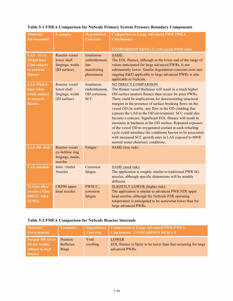
5-30
Table 5-1 FMEA Comparison for NuScale Primary System Pressure Boundary Components
Material / Environment
Examples Degradation Concerns
Comparison to Large Advanced PWR FMEA Conclusions:
COMPARISON RESULT (Advanced PWR risk) LAS - SS or Nickel-base Clad subject to neutron fluence
Reactor vessel lower shell forgings, welds (ID surface)
Irradiation embrittlement, late manifesting phenomena
SAME: The EOL fluence, although in the lower end of the range of values anticipated for large advanced PWRs, is not substantially lower. Similar degradation concerns exist and ongoing R&D applicable to large advanced PWRs is also applicable to NuScale.
LAS (Nickel-base Alloy Clad) subject to neutron fluence
Reactor vessel lower shell forgings, welds (ID surface)
Irradiation embrittlement, OD corrosion, SCC
NO DIRECT COMPARISON The thinner vessel thickness will result in a much higher OD surface neutron fluence than occurs for prior PWRs. There could be implications for demonstrating structural margins in the presence of surface breaking flaws on the vessel OD (in reality, any flaw in the OD cladding that exposes the LAS to the OD environment. SCC could also become a concern. Significant EOL fluence will result in increases in hardness at the OD surface. Repeated exposure of the vessel OD to oxygenated coolant at each refueling cycle could introduce the conditions known to be associated with increased SCC growth rates in LAS exposed to BWR normal water chemistry conditions.
LAS (SS clad) Reactor vessel ex-beltline ring forgings, heads, nozzles
Fatigue SAME (low risk)
LAS (unclad) Inlet / Outlet Nozzles
Corrosion fatigue
SAME (med risk): The application is roughly similar to traditional PWR SG nozzles, although specific dimensions will be notably different.
Ni-base alloy nozzles (Alloy 690TT, Alloy 52/152)
CRDM upper head nozzles
PWSCC, corrosion fatigue
SLIGHTLY LOWER (higher risk): The application is similar to advanced PWR PZR upper head nozzles, although the NuScale PZR operating temperature is anticipated to be somewhat lower than for large advanced PWRs.
Table 5-2 FMEA Comparison for NuScale Reactor Internals
Material / Environment
Examples Degradation Concerns
Comparison to Large Advanced PWR FMEA Conclusions: COMPARISON RESULT
Forged 300 series SS (no welds) subject to high fluence
Neutron Reflector Rings
Void swelling
LOWER EOL fluence is likely to be lower than that occurring for large advanced PWRs.
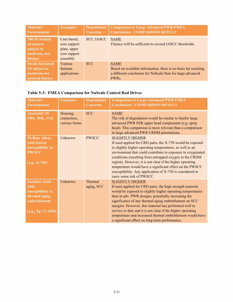
5-31
Material / Environment
Examples Degradation Concerns
Comparison to Large Advanced PWR FMEA Conclusions: COMPARISON RESULT
300 SS welded structures subject to moderate, low fluence
Core barrel, core support plate, upper core support assembly
SCC, IASCC SAME Fluence will be sufficient to exceed IASCC thresholds.
Strain hardened SS subject to moderate-low neutron fluence
Various fastener applications
SCC SAME Based on available information, there is no basis for reaching a different conclusion for NuScale than for large advanced PWRs.
Table 5-3: FMEA Comparison for NuScale Control Rod Drives
Material / Environment
Examples Degradation Concerns
Comparison to Large Advanced PWR FMEA Conclusions: COMPARISON RESULT
Austenitic SS (304, 304L, 316)
Housing, connectors, various forms
SCC SAME: The risk of degradation would be similar to thatfor large advanced PWR PZR upper head components (e.g. spray head). This comparison is more relevant than a comparison to large advanced PWR CRDM penetrations.
Ni-Base Alloys with known susceptibility to PWSCC
(e.g., X-750)
Unknown PWSCC SLIGHTLY HIGHER If used applied for CRD parts, the X-750 would be exposed to slightly higher operating temperatures, as well as an environment that could contribute to exposure to oxygenated conditions (resulting from entrapped oxygen in the CRDM region). However, it is not clear if the higher operating temperature would have a significant effect on the PWSCC susceptibility. Any application of X-750 is considered to carry some risk of PWSCC.
Stainless steels with susceptibility to thermal aging embrittlement
(e.g., Tp. 17-4PH)
Unknown Thermal aging, SCC
SLIGHTLY HIGHER If used applied for CRD parts, the high strength material would be exposed to slightly higher operating temperatures than in adv. PWR designs, potentially increasing the significance of any thermal aging embrittlement on SCC margins. However, this material has performed well in service to date and it is not clear if the higher operating temperature and increased thermal embrittlement would have a significant effect on long-term performance.
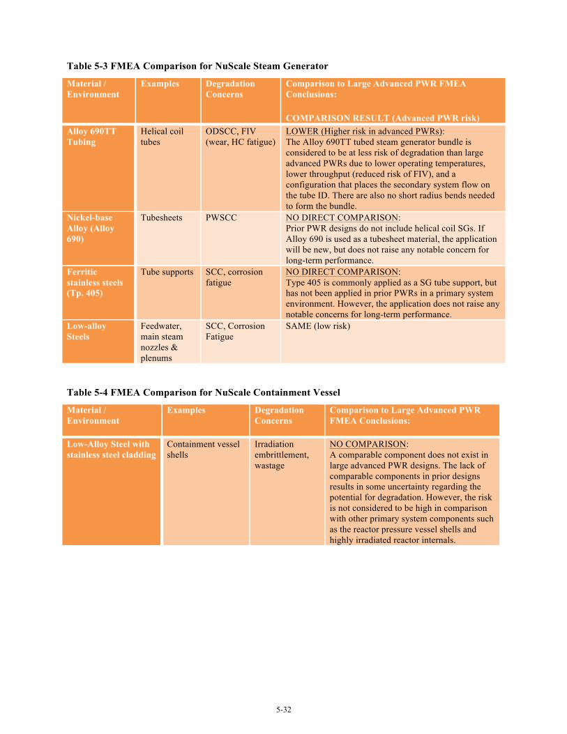
5-32
Table 5-3 FMEA Comparison for NuScale Steam Generator
Material / Environment
Examples Degradation Concerns
Comparison to Large Advanced PWR FMEA Conclusions:
COMPARISON RESULT (Advanced PWR risk) Alloy 690TT Tubing
Helical coil tubes
ODSCC, FIV (wear, HC fatigue)
LOWER (Higher risk in advanced PWRs): The Alloy 690TT tubed steam generator bundle is considered to be at less risk of degradation than large advanced PWRs due to lower operating temperatures, lower throughput (reduced risk of FIV), and a configuration that places the secondary system flow on the tube ID. There are also no short radius bends needed to form the bundle.
Nickel-base Alloy (Alloy 690)
Tubesheets PWSCC NO DIRECT COMPARISON: Prior PWR designs do not include helical coil SGs. If Alloy 690 is used as a tubesheet material, the application will be new, but does not raise any notable concern for long-term performance.
Ferritic stainless steels (Tp. 405)
Tube supports SCC, corrosion fatigue
NO DIRECT COMPARISON: Type 405 is commonly applied as a SG tube support, but has not been applied in prior PWRs in a primary system environment. However, the application does not raise any notable concerns for long-term performance.
Low-alloy Steels
Feedwater, main steam nozzles & plenums
SCC, Corrosion Fatigue
SAME (low risk)
Table 5-4 FMEA Comparison for NuScale Containment Vessel
Material / Environment
Examples Degradation Concerns
Comparison to Large Advanced PWR FMEA Conclusions:
Low-Alloy Steel with stainless steel cladding
Containment vessel shells
Irradiation embrittlement, wastage
NO COMPARISON: A comparable component does not exist in large advanced PWR designs. The lack of comparable components in prior designs results in some uncertainty regarding the potential for degradation. However, the risk is not considered to be high in comparison with other primary system components such as the reactor pressure vessel shells and highly irradiated reactor internals.
6-1
6.0 Materials R&D Gap Assessment Results In presenting gap assessment results, gaps identified for large advanced PWRs are used as a
baseline for evaluation of LWSMR materials R&D needs. Section 6.1 provides a summary discussion of significant materials R&D gaps associated with large advanced PWRs. Unless noted otherwise in Sections 6.2 or 6.3, these gaps are generally applicable to LWSMRs. Section 6.2 provides a high-level comparison of materials selection, environmental conditions and design configuration between large advanced PWRs and the mPower and NuScale LWSMR designs examined. Section 6.3 summarizes the materials performance concerns and materials R&D opportunities identified for LWSMRs.
6.1 Large Advanced PWR Baseline Materials R&D Needs
Six broad areas of materials R&D were identified by the evaluation of large advanced PWRs and are summarized in Sections 6.1.1 through 6.1.6. The identified R&D needs do not represent deficiencies in design, but rather represent opportunities for margin improvement or optional approaches for improved probabilities of long-term resistance to materials degradation. In some cases, there are areas where available industry guidance is lacking, even if specific vendor practices may have addressed the concern.
6.1.1 Performance of High Chromium, Nickel-Base Alloys 690, 52 and 152
Alloy 690 and its weld metals normally exhibit extremely low PWSCC growth rates in laboratory testing, but data has shown that accelerated stress corrosion crack growth rates can occur in cold-worked material. For the tests in question, cold working was applied to the material to simulate the strains introduced by weld shrinkage. As a result, there is some concern that the data showing accelerated crack growth rates could be applicable to weld heat affected zones. There is also a lack of long-term operating experience with this alloy, especially in thick sections such as CRDM nozzles. While operating experience to date has been successful, some experts remain of the opinion that longer operating periods with no problems and/or additional test data relevant to plant component configurations are needed to have adequate confidence in Alloy 690 for operation to 60 or more years.
When produced in heavy sections, Alloy 690 (as well as other nickel alloys) has a tendency to form microstructural banding. This banding can be in the form of grain size banding, carbide banding, chemistry banding (e.g. bands of higher or lower carbon content), or impurity banding. Although banding can be avoided with proper material processing, it has been commonly observed in material produced for nuclear applications, particularly in forged billet and plate. There is some suspicion that crack growth rates could be accelerated in some of the banded structures. In addition, severe banding may affect mechanical properties 90 degrees to the banding. Finally, although not specifically a materials degradation issue, coarse grain banding can cause difficulties in performing adequate ultrasonic examinations. As a result, there is a need to address these uncertainties, preferably through near-term testing, such that any inherent material vulnerabilities are identified and addressed as early as possible in the “service life” of Alloys 690, 52 and 152.
In addition to concerns regarding long-term PWSCC vulnerability, there are concerns related to machinability and weldability of Alloys 690, 52 and 152. It has been observed that machining these
6-2
high chromium nickel alloys can result in fissuring and tearing of the surface. Fabricators that have been actively involved in using Alloy 690 for building replacement components have developed in-house procedures to avoid this problem, but there is no general recognition of the concern outside these relatively few vendors. Consequently there is no publically available guidance on how to machine Alloy 690/52/152 in a way that avoids surface tearing. Weldability of these high chromium alloys also remains an issue, with both ductility dip cracking and hot cracking being concerns. Various attempts at adjusting the formulation have not been totally successful at simultaneously addressing both cracking phenomena. In addition, applying these alloys to other materials (e.g. stainless steels) having moderate sulfur levels has been problematic. Further work on improved chemical formulations is needed as well as industry guidance on acceptable levels of sulfur in mating materials.
6.1.2 Reactor Vessel Integrity
There is some evidence of damage phenomena that manifest at neutron fluences > ~5x10¹⁹ n/cm2 (E > 1.0 MeV) resulting in additional embrittlement not previously considered or anticipated by predictive models. Depending on flux conditions, these embrittlement phenomena likely include a combination of Ni-Mn-Si clustering, stable matrix features, and thermally unstable matrix defects. If nearly pure manganese/nickel-rich precipitates do eventually form, significant additional embrittlement could occur, even in the low-copper steels used for advanced PWR reactor vessel construction. These additional embrittlement phenomena are not sufficiently characterized or well represented in current power reactor embrittlement models. Development of additional data through testing programs that provide data in relatively short time periods and that address the effects of neutron flux is viewed to be a strategic issue for the industry for PWRs of all vintages. Although concerns are significantly mitigated in advanced large PWRs by the use of material having good chemistry and unirradiated toughness, understanding the significance of late occurring embrittlement phases is of value for new plants.
A related fabrication concern is the potential for macro-segregation to result in overly conservative embrittlement estimates. Due to macro-segregation, significant differences in carbon content can occur between the center of a beltline shell forging and the bottom or top edge of the forging. While it was demonstrated that this did not appreciably affect mechanical or toughness properties, if similar segregation occurs in elements that influence the rate and extent of radiation damage, surveillance specimens taken from the edges of the forging may not accurately represent the center of the beltline. At the least, any variations in chemistry within the forging should be determined and recorded.
6.1.3 Residual Stress Evaluation - SCC Mitigation Capabilities & Guidance
There is a need to better understand the relative vulnerabilities to SCC associated with high tensile residual stresses and to quantify/demonstrate the benefits of 1) fabrication processes that reduce or eliminate surface tensile residual stresses and 2) mitigation techniques. In particular for new plant designs, the long-term benefits of stress improvement techniques have not been comprehensively evaluated. Given that there are few data that can be used to assess the long-term SCC performance of materials that have performed relatively well in service thus far, most new plant vendors do not plan to include stress reduction technologies in their standard designs. R&D that identifies, matures and quantifies the benefits of low added cost or even cost-neutral stress reduction technologies is needed. With specific regard to surface stress improvement techniques (e.g., laser peening, water jet peening), the thickness of the resulting compressive stress layer can be relatively thin. If the benefits of stress
6-3
improvement are reduced or lost over many operating cycles due to fatigue cycling, for example, SCC could eventually occur. As a result, there is an additional need to assess the potential that mitigations performed prior to unit startup might not remain effective for the entire plant service live, particularly given that load follow capability will be desirable.
In addition to the fundamental R&D needs described above, there are some specific areas where industry guidance would appear to be needed:
• Primary System Piping and Dissimilar Metal Weld Process Control and Optimization: Conventional pipe welding produces high degrees of tensile residual stresses on the inside of the weld joint (the surface normally exposed to reactor coolant). Weld processes have been developed that are capable of reducing tensile residual stresses or reversing stresses to compressive on the pipe inside surface. Additionally, post weld processes have been developed and applied to operating plants that can provide stress reversal (IHSI, MSIP®) or otherwise put the inside of the pipe in a compressive stress state (various peening/polishing processes). However, there is currently no industry guidance to apply any of these processes to construction of new plants.
• Weld and HAZ Surface Condition Guidance: It is known that the surface condition of weld zones can influence susceptibility to environmentally induced cracking, particularly SCC. Surface cold work and stress state are both potentially damaging. Surface cold work can readily be introduced by common fabrication processes (machining, grinding, cold forming, etc.). These processes may simultaneously introduce tensile stresses to the surface. Currently there is no industry guidance to address process qualification and control, or application of mitigating processes such as polishing to remove surface cold work or peening to produce compressive surface stresses.
6.1.4 Environmental Effects on Fatigue Resistance
Initial design of primary system components has in the past included a basic assumption that, for most cases, exposure to the environment does not significantly affect fundamental material mechanical properties. Although there has been significant industry debate in recent years, it is now generally accepted that exposure to the coolant environment does have some effect on material properties. With regard to fatigue resistance, the design curves that provide the basis for fatigue assessment of primary system components have traditionally not explicitly accounted for an effect of environment. With Regulatory Guide 1.207, NRC now requires designs to consider environmental effects. R.G. 1.207 is based on data obtained from laboratory tests on small specimens in simulated LWR environments. These data are developed in the same way as data for fatigue in air were previously developed and clearly indicate that environmental effects are real and that fatigue resistance in a reactor water environment is lower than previously assumed based on testing in “dry air.” This conclusion is reasonable based on the significant database resulting from laboratory tests on small specimens in simulated primary coolant system environments, regardless of the good field performance observed to date.
The consequence of generic application of the R.G. 1.207 fatigue environmental factors is that some component designs that conform to the ASME requirement of fatigue usage less than 1.0, fail to meet the criterion when the environmental factors of the Regulatory Guide are applied. This situation is complicated by a lack of clarity regarding how the environmental factors are to be applied with respect
6-4
to such topics as fatigue cycle counting, load application rates, enveloping of components to minimize new analyses, etc. At this time, the system designers are each applying their own approach, so there is no industry consensus on methodology. There is also an industry concern that the environmental factors are based mainly on laboratory testing of uniaxial specimens that don’t accurately represent the behavior of actual, three dimensional, plant component configurations.
There are substantial conservatisms already included in the fatigue analyses from both the ASME Code design curves and design transient assumptions applied by vendors. Application of R.G. 1.207 environmental factors is likely overly conservative and could result in arbitrary limits on operation. With the economic desirability of plant operation for 80 years and load-follow capability, there is a clear need for industry to better understand the effect of environment on actual plant components.
6.1.5 Effects of Material Composition and Fabrication Processes on Irradiation-Induced Degradation
Material chemistry can influence the tendency to various forms of irradiation-induced degradation (IASCC, embrittlement and void swelling). However, there is little publically available data that can be used to associate different material chemical compositions with relative susceptibility to the various irradiation-induced degradation phenomena. Work to identify desirable material compositions, or conversely, undesirable species for new plant construction would be of considerable benefit to the industry. Additionally, uncertainties remain regarding the influence of material processing on long-term susceptibility to irradiation-induced degradation. The effects of cold work (bulk and surface) and weld residual strain (essentially warm work) on these phenomena are not well characterized. Consequently, there are insufficient data to support a specific set of recommendations for process controls or for application of mitigation processes (e.g., surface peening and/or polishing). Work to clarify the effects of cold work and strain in irradiated materials with respect to the impact on degradation phenomena and long-term performance would be beneficial to the industry.
In addition to the materials R&D issues, there are at least two areas where some additional industry guidance would be beneficial.
• Boron in stainless steel can generate helium under neutron irradiation. Elevated levels of helium will cause cracking of stainless steel during welding. This can become an issue in the event that welded repairs of stainless steel reactor internals are needed.7 Relative weldability of irradiated stainless steel can be determined by calculation if the initial boron content and neutron fluence are known. However, currently there are no limitations on boron levels in stainless steel or even any requirement that the boron content be measured and recorded. While not directly a materials performance concern, this gap observes that guidance on the limitation or at least documentation of boron levels in irradiated stainless steel internals would be beneficial to the industry.
• Currently, there is no industry guidance on appropriate and optimized weld processes for reactor internals construction. Stainless steel welds made with flux shielded processes are known to have lower toughness than non-flux processes. Additionally, there is some evidence that welds made with flux shielded processes experience greater reductions in toughness with neutron irradiation. Modern application of non-flux processes by automated systems in conjunction with narrow gap welding can provide high quality joints (few, if any, defects) that compete with the high
7 The most likely location for application of a welded repair solution in any advanced PWR would be the core barrel shell circumferential welds.
6-5
deposition rates of flux shielded processes. Industry guidance on selection and application of weld processes for reactor internals would be beneficial to the industry, especially for irradiated components where structural margins are reduced over time due to irradiation embrittlement.
6.1.6 Steam Generator Long-Term Performance
Currently it is supposed that the use of Alloy 690TT tubing will eliminate the primary life limiting degradation concern in steam generators from previous generation plants that had Alloy 600 tube bundles. While this may be the case for primary-side SCC, secondary-side SCC remains a significant concern for many experts due to impurity concentration (particularly lead) at line-contact crevices). It is also possible that a new or different degradation phenomenon may become the next life limiting issue. This gap proposes evaluation of steam generator design for enhancements in configuration and materials selection that can address other life limiting concerns; such as debris and loose parts, flow-accelerated corrosion, and fouling by corrosion product deposition. The objective would be to provide increased confidence in long-term integrity and serviceability of steam generators for advanced PWRs, ensuring service through a 60-year design life and potentially supporting an 80-year service life.
Steam generator modeling capabilities represents a related area of R&D need. Operating experience has shown that unexpected fluid flow conditions in new steam generator designs can result in FIV and subsequent tube failures. Whether caused by unidentified harmonics in newly installed generators or by redistribution of flow caused by fouling at tube-tube support flow channels, it is known that current analysis tools available to the industry have limitations and need to be improved. Regardless of design, flow conditions in some parts of steam generators are not well understood or well predicted by the current code (EPRI’s Steam Generator Fatigue/Wear). Further, these analysis tools were developed to address Gen II plant designs and cannot be directly applied to most large advanced PWR steam generator designs.
6.2 LWSMR Design Comparison
To provide a starting point for identifying materials R&D needs for LWSMRs, it is valuable to compare LWSMRs with large advanced PWRs with regard to materials selection, environmental conditions and design configurations. Although this type of comparison is acknowledged to be a relatively rudimentary approach, there are few additional data to use in distinguishing differences between large advanced PWRs and LWSMRs. Factors such as specific joint configurations or the specified welding processes, fabrication process controls, and any mitigations planned are either beyond the level of detail currently available in these designs or are deemed confidential by the vendor until a design certification application is made to NRC. In addition, where new design configurations are introduced that necessarily will involve new or modified materials fabrication and processing procedures, there is a possibility of introducing unanticipated materials performance vulnerabilities, even when the material of construction and environmental exposure is similar to prior plant designs.
Table 6-1 compares materials selection/fabrication and environmental conditions between a typical large advanced PWR and the mPower and NuScale LWSMR designs. Bold text highlights cases where either LWSMR designs potentially are not enveloped by the large advanced designs reviewed. Italicized text indicates areas where the LWSMR designs are clearly bounded by large plant designs. Table 6-2 provides a high-level comparison of design and operational characteristics between a typical large advanced PWR and the mPower and NuScale LWSMR designs. These tabular comparisons are
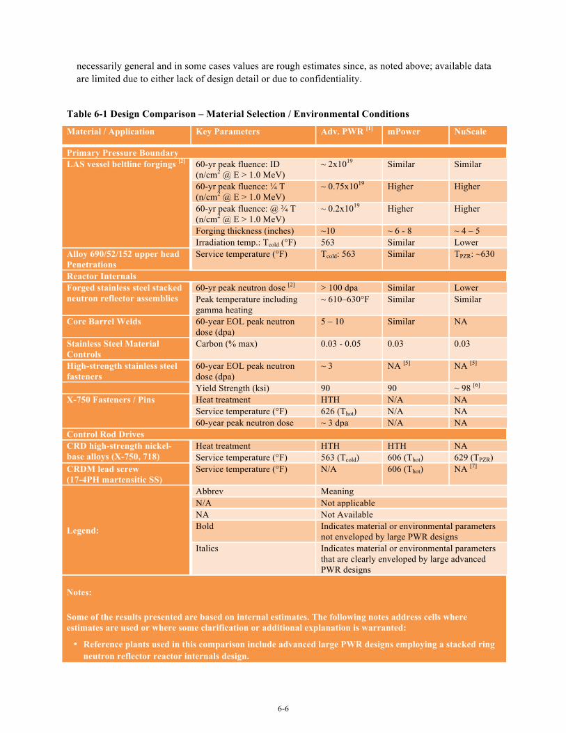
6-6
necessarily general and in some cases values are rough estimates since, as noted above; available data are limited due to either lack of design detail or due to confidentiality.
Table 6-1 Design Comparison – Material Selection / Environmental Conditions
Material / Application Key Parameters Adv. PWR [1] mPower NuScale
Primary Pressure Boundary LAS vessel beltline forgings [2] 60-yr peak fluence: ID
(n/cm2 @ E > 1.0 MeV) ~ 2x10¹⁹ Similar Similar
60-yr peak fluence: ¼ T (n/cm2 @ E > 1.0 MeV)
~ 0.75x10¹⁹ Higher Higher
60-yr peak fluence: @ ¾ T (n/cm2 @ E > 1.0 MeV)
~ 0.2x10¹⁹ Higher Higher
Forging thickness (inches) ~10 ~ 6 - 8 ~ 4 – 5 Irradiation temp.: Tcold (°F) 563 Similar Lower
Alloy 690/52/152 upper head Penetrations
Service temperature (°F) Tcold: 563 Similar TPZR: ~630
Reactor Internals Forged stainless steel stacked neutron reflector assemblies
60-yr peak neutron dose [2] > 100 dpa Similar Lower Peak temperature including gamma heating
~ 610–630°F Similar Similar
Core Barrel Welds 60-year EOL peak neutron dose (dpa)
5 – 10 Similar NA
Stainless Steel Material Controls
Carbon (% max) 0.03 - 0.05 0.03 0.03
High-strength stainless steel fasteners
60-year EOL peak neutron dose (dpa)
~ 3 NA [5] NA [5]
Yield Strength (ksi) 90 90 ~ 98 [6] X-750 Fasteners / Pins Heat treatment HTH N/A NA
Service temperature (°F) 626 (Thot) N/A NA 60-year peak neutron dose ~ 3 dpa N/A NA
Control Rod Drives CRD high-strength nickel-base alloys (X-750, 718)
Heat treatment HTH HTH NA Service temperature (°F) 563 (Tcold) 606 (Thot) 629 (TPZR)
CRDM lead screw (17-4PH martensitic SS)
Service temperature (°F) N/A 606 (Thot) NA [7]
Legend:
Abbrev Meaning N/A Not applicable NA Not Available Bold Indicates material or environmental parameters
not enveloped by large PWR designs Italics Indicates material or environmental parameters
that are clearly enveloped by large advanced PWR designs
Notes:
Some of the results presented are based on internal estimates. The following notes address cells where estimates are used or where some clarification or additional explanation is warranted:
• Reference plants used in this comparison include advanced large PWR designs employing a stacked ring neutron reflector reactor internals design.
6-7
• Vessel thickness and fluence information for the LWSMRs was limited. However, sufficient data were available to develop rough estimates of fluence that occurs through the vessel thickness in the LWSMR designs evaluated. Rough estimates of vessel thickness were developed using known design information (design pressure and temperature, vessel diameter). Estimates of fluence attenuation for LWSMRs were made by assuming an attenuation rate similar to that known to exist for large advanced PWRs.
• The 60-year peak dose for a heavy reflector varies by design. For large PWRs, this value will certainly exceed 100 dpa and may be as high as 150 dpa. For the mPower design, a somewhat higher EOL dose is anticipated based on the higher 60-year fluence estimate provided by B&W for the vessel shell.
• NuScale provided a core reflector 60-yr neutron dose estimate 50 – 80 dpa. This value seems low in comparison with the typical values known to exist for large advanced PWR designs.
• The mPower core basket is assumed to have rolled and welded plate construction, with 60-year neutron dose estimates similar to those occurring in large advanced PWRs.
• Minimal fluence exposure is anticipated for any high-strength fasteners used.
• NuScale specifies high-strength fasteners to have a limit of 20% cold work. As a general approximation, this limit equates to a yield strength of 97 – 98 ksi, in excess of the typical limit of 90 ksi placed on high-strength stainless steel fasteners in other designs.
• A detailed list of materials associated with the NuScale CRDs is not available.
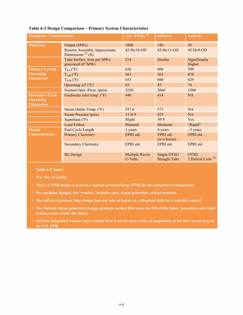
6-8
Table 6-2 Design Comparison – Primary System Characteristics
Parameter / Characteristic Adv. PWRs [1] mPower NuScale
Plant Size Output (MWe) 1600 180 45 Reactor Assembly Approximate Dimensions [1] (ft)
42-Hx18-OD 83-Hx13-OD 45-Hx9-OD
Tube Surface Area per MWe generated (ft2/MW)
214 Similar Significantly Higher
Primary System Operating Parameters
Thot (°F) 626 606 590 Tcold (°F) 563 563 478 TPZR (°F) 653 660 629 Operating ΔT (°F) 63 43 74
Normal Oper. Press. (psia) 2250 2060 1500 Secondary Cycle Operating Parameters
Feedwater inlet temp. (°F) 446 414 NA
Steam Outlet Temp. (°F) 557.6 571 NA Steam Pressure (psia) 1110.9 825 NA Superheat (°F) Slight 50°F Yes Load Follow Minimal Moderate “Rapid” Design Characteristics
Fuel Cycle Length 2 years 4 years ~3 years Primary Chemistry EPRI std. EPRI std.
(w/o boron) EPRI std.
Secondary Chemistry EPRI std. EPRI std. EPRI std.
SG Design Multiple Recirc U-Tube
Single OTSG Straight Tube
OTSG 2 Helical Coils [3]
Table 6-2 Notes:
• NA: Not Available
• The U.S. EPR design is used as a typical advanced large PWR for the purposes of comparison.
• For modular designs, the “reactor” includes core, steam generator, and pressurizer.
• The mPower primary loop design does not rely on boron as a chemical shim for reactivity control.
• The NuScale steam generator design, primary coolant flow is on the OD of the tubes. Secondary-side fluid boiling occurs inside the tubes.
• mPower integrated reactor mass coolant flow is on the same order of magnitude as the flow in one loop of the U.S. EPR.
6-9
6.3 LWSMR Materials R&D Needs
In most all cases, the R&D needs summarized in Section 6.1 above are also applicable to the LWSMR designs evaluated. Relatively few unique materials R&D issues were identified for LWSMRs. This result is reasonable, given that materials application and environmental conditions for LWSMR primary systems will be largely the same as those occurring for large advanced PWRs. However in a few cases, there are issues unique to LWSMR designs that warrant some consideration in future LWR R&D plans. These are summarized in Sections 6.3.1 through 6.3.6 below.
6.3.1 Performance of Alloy 690 and its Weld Metals
Concerns related to Alloy 690, 52 and 152 long-term PWSCC resistance are generally the same for both large advanced PWRs and LWSMRs. However, at least one LWSMR design will include a component configuration/environmental exposure condition that is different than those used in large advanced PWRs. Specifically, this vessel design includes a number of CRD nozzles located in the upper dome of the reactor vessel. The nozzle design includes low-alloy steel nozzles welded to an Alloy 690 extension tube, which is then welded to the stainless steel CRD housing. Welds are made with Alloy 52/152 materials. Although not dramatically different than used for Gen III / III+ pressurizer upper head nozzles, the configuration does include an Alloy 690 extension tube and subjects the connection to steam at a pressurizer temperature of ~630°F. Given this configuration, R&D that improves the industry state of knowledge related to the effects of welding (residual stress/strain, effects on base metal microstructure), demonstrates benefits associated with compressive stress welding, or improves the capability to assess PWSCC initiation risk would be beneficial.
6.3.2 Reactor Vessel Embrittlement
Radiation embrittlement from long-term exposure of reactor vessels has not been considered to be a significant issue for the large advance PWRs. Use of modern LASs with low copper levels and low initial RTNDT maintains the shift in transition temperature to a manageable level over the life of the unit, even when considering the potential for operation beyond the 60-year design life. LWSMR designs will employ similar controls on the material chemistry of the LAS beltline shells and will likely have EOL fluence values similar to large advanced PWRs. As a result, no unique concern exists for LWSMRs with regard to this specific issue. However because the thickness of LWSMR reactor vessels is considerably less than large PWR units, significant radiation damage occurs through a greater fraction of the total wall thickness. As a result, some study may be necessary to determine if this observation is significant, most likely in the context of demonstrating structural margins for all design conditions (for example, the current industry issue related to postulation of small surface breaking flaws in pressurized thermal shock evaluations). Although not likely to be a significant materials R&D need, some evaluation is warranted ensure that there are no unexpected challenges to structural integrity margins.
Additionally, note that the macro-segregation concerns highlighted in Section 6.1.2 are substantially mitigated by the thinner forging thickness used in LWSMR designs.
6-10
6.3.3 Assessment of Environmental Fatigue Effects
Environmental fatigue margins could be of increased significance for any LWSMR design, due to operating economics that make load-follow capability important, if not critical, to the design. Whereas large plants at present are typically deployed for base load in the U.S. and likely will never be subject to high levels of load follow, SMRs will necessarily be operated with at least moderate load follow. Although the designs likely will address both load follow assumptions and environmental effects through 60 years of operation, there would be some question as to the margin available in fatigue evaluations for more substantial load follow, operation beyond 60 years, or some combination of these two scenarios. Conversely, LWSMR installations that involve multiple reactors could provide flexibility in meeting load demands that are not available for a large plant site and thus mitigate load follow concerns. Therefore, there is a need to ensure that materials R&D plans include consideration of LWSMRs to ensure that R&D results are adequate to address specific LWSMR component configurations and the operational assumptions.
6.3.4 Highly Irradiated Materials Performance Data
Based on the estimated neutron dose to the reactor vessel wall, it appears the highly irradiated internals in some LWSMR designs could have EOL neutron fluence at the upper end of the range known to exist for large advanced PWRs. Additionally, the peak temperature considering gamma heating will be sufficiently high to make void swelling a possibility under the long-term exposure conditions. Although the stacked ring structure used by the LWSMR designs evaluated mitigates IASCC concerns, it is not clear that ongoing research focused on characterizing void swelling in Gen. II PWRs will envelope LWSMR operating conditions. Specifically, the EPRI co-sponsored Gondol Phase 2 project is presently focused on irradiation conditions expected for the operating fleet of PWRs. It appears that both large advanced PWRs and LWSMR designs will go beyond the fluence levels in the current test matrix and will be operating with peak temperatures to the high side of the range (if not beyond), for the current test matrix. Since Gondol Phase 2 is currently planned to run through 2018, there may be some opportunity to join the project and add specimens to the matrix that will more closely represent advanced PWR and LWSMR irradiation conditions.
The risk of heavy reflector swelling could be mitigated by selection of one or more advanced austenitic stainless steel alloys, such as Alloy D9 or HT-UPS. Although originally developed with the objective of providing advanced materials for next generation (Gen IV) high-temperature nuclear designs and high temperature fossil applications, these alternative materials are being studied as part of a recent EPRI initiative to identify and develop new stainless steel alloys for highly irradiated reactor internals. These materials may provide higher resistance to irradiation creep, void swelling, and IASCC. However, additional work is needed to characterize performance in a LWR environment. R&D efforts in this area should be balanced against the likely benefits obtained. Given the relatively good performance of “standard” stainless steels in PWR service to date and considering the significant improvements to core former design, there may be a rather limited need for these advanced alloys in LWSMR applications.
6.3.5 Steam Generator Design
Evaluation of available LWSMR designs indicates that steam generator design will be an area of significant difference from large advanced PWRs. Although in most cases similar materials are used,
6-11
there are some cases of new applications for the materials and differences in configuration that will result in different fabrication approaches.
Helical Coil Tube Configuration The NuScale design will include a helical coil steam generator. Fabrication of the helical coil configuration requires a significant change in fabrication approach. Organizations familiar with optimizing Alloy 690 for use in LWR steam generator service may not have this experience. Conversely, organizations that are familiar with helical coil heat exchanger fabrication may not have significant experience with optimizing tube microstructure and surface condition for LWR service. Additionally, it is not known if it will be possible to apply the thermal treatment that normally occurs after the steam generator tubes have been cold formed. If it is necessary to put the formed Alloy 690 helical coil tubes in service without post forming thermal treatment, this will represent new material condition for a PWR steam generator. There will be no service experience and laboratory data supporting use of Alloy 690 in this condition may be limited or non-existent. This concern may be mitigated somewhat because the amount of cold strain required to form the helical coil may be less than that to form U-tubes for a conventional steam generator. Nonetheless, it still will be a material condition that has not been proven by prior LWR operating experience.
Ferritic SS Tube Supports The NuScale design includes use of ferritic SS tube supports. Although not a new material, use of ferritic SS in a PWR primary water environment is an application that has not been used in previous PWR designs. As a result, some evaluation of material performance may be justified.
Carbon Steel Tube Supports The mPower design includes use of carbon steel spacers in the steam generator. This a departure from recent large plant design as none of the large advanced PWR steam generator designs use carbon steel tube supports. The EPRI Utility Requirements Document for Advanced Light Water Reactors flatly prohibits the use of carbon steel spacers based on the tube denting experience in earlier designs. B&W notes that there have been no problems with use of carbon steel spacers in their OTSG designs while increased wear was observed when martensitic stainless steel (Type 410) was used with Alloy 690 tubes and that there are fundamental performance differences between once-through designs and recirculating designs. In addition, the carbon steel for spacer fabrication will be ordered with about 0.1% chromium content to provide a modest level of resistance to corrosion and flow accelerated corrosion. Regardless, it is considered that the continued use of carbon steel should be approached with some caution considering 60 year operating life and the prior experience of tube denting in other steam generator designs. Within commercial LWR operation, there is no experience with very long steam generator service times with carbon steel tube supports (since most early Gen. II designs were replaced due to Alloy 600 tubing SCC). Additionally, if operation beyond 60 years is an important economic consideration for utilities, additional study may be warranted to address long-term performance vulnerabilities. For the mPower design the steam generator is integral to the upper vessel, therefore steam generator replacement would require replacement of the entire upper vessel assembly.
Regardless of the significance or validity of these three examples, they highlight notable differences in design from large advanced PWRs. As a result, materials R&D focused on mitigating degradation in large recirculating steam generators having U-bend tube bundles will not be directly applicable to most LWSMR designs. Development of dispersants targeted for use in recirculating SGs will not be applicable to once-through designs. Finally, improved thermohydraulic models focused on large recirculating steam
6-12
generators will not be useful for evaluation of LWSMRs. As a result, steam generator design represents an area where there could be several opportunities for materials R&D targeted at LWSMR designs.
6.3.6 Flow-Induced Vibration Evaluation
LWSMRs will introduce significantly different CRD configurations. The mPower reactor design will include CRDMs that are mounted as reactor internal components within the vessel itself. The NuScale CRD design includes relatively long connecting rods attaching the neutron absorbing section to the drives located above the vessel. These connecting rods are longer than in prior PWR designs, simply because the added height of the steam generator and pressurizer sections. Although there are no specific concerns for either of these design configurations, unanticipated flow-induced effects occurring in PWR upper plenum components and BWR steam dryers illustrate the complexities involved. Even in regions of relatively low fluid velocity and turbulence significant wear has occurred at a few plants due to harmonics/oscillations.
The NuScale helical coil steam generators represent a second example. Flow patterns through the tube bundle and the approach toward tube support will be dramatically different than either recirculating or once-through steam generator designs. Tube support plates will not be necessary. Rather, tube spacing will likely be established by clamps positioned throughout the tube bundle. Although unique in configuration, it is noted that the NuScale design appears to be less susceptible to FIV than traditional designs, since it essentially eliminates concerns associated with blockage of tube to tube support flow openings. However, some study is potentially needed to confirm this conclusion.
Generically, the potential for FIV is a concern for any new reactor design. Recent experience (i.e., San Onofre, Oconee) indicate that even where configuration is very similar to proven designs there can be significant unanticipated vibratory loading caused by small changes in design or fabrication techniques and that are not well anticipated by current models. As a result, efforts to improve modeling capabilities related to flow-induced loading of reactor internals and steam generators is an area of potential R&D need for LWSMRs. Notably since each LWSMR design will be very different, any R&D must either be narrowly focused on one design or alternatively broadly focused on fundamental mechanistic capabilities that allow for application and extrapolation to many configurations.
7-1
7.0 Conclusions The assessment of materials R&D needs for LWMRs is facilitated by a baseline review of large Gen
III and Gen III+ advanced PWR designs in this report. This approach was found to have substantial merit since LWSMR designs have been heavily influenced by the more mature large advanced PWR designs. The conclusions in this section are organized similarly. Section 7.1 presents conclusions from the baseline evaluation of large advanced PWRs. Section 7.2 presents conclusions for the LWSMR designs evaluated and builds on the results of Section 7.1.
7.1 Large Advanced PWRs
In developing the large Gen III and Gen III+ advanced PWR designs, vendors have taken action to address the most significant materials performance issues faced by operating PWRs through selection of different materials, material specification refinements, and changes in design configuration.
Material selection changes include:
• Replacement of PWSCC susceptible Alloys 600, 82, 182 and 132 by higher Cr Alloys 690, 52 and 152.
• Replacement of stabilized stainless steel fasteners with strain-hardened Type 316 stainless steel fasteners (that typically include a 90 ksi limit on yield strength).
Material specification refinements include:
• Alloy X-750 is treated in the HTH condition and limits on design loads are specified to minimize the potential for PWSCC.
• Austenitic stainless steels specified for primary pressure boundary service and reactor internals are often specified with limits on carbon content and weld metal ferrite content to reduce the risk of SCC and limit thermal aging of welds.
• Pressure vessel LASs are all SA-508, Grade 3 with tight materials chemistry controls applied to mitigate the effects of neutron fluence on material toughness.
Design configuration changes include:
• Bolted core shroud configurations have been replaced either with a welded core shroud or, more commonly, with a stacked neutron reflector. Use of a neutron reflector significantly reduces the potential for IASCC and provides some neutron shielding for the core barrel and reactor vessel wall.
• Application of high-strength fasteners within the core internals is minimized and, where necessary, design and materials processing controls are applied to reduce the potential for SCC.
As a result, the risk of primary system materials performance problems is substantially reduced relative to that of Gen. II operating PWRs. The risk of short-term degradation is all but eliminated since the improvements mentioned above, and others not listed, were direct responses to degradation observed in operating PWRs. However, there remains some uncertainty regarding long-term performance for some
7-2
material applications, typically where there is no direct experience from operating reactors to draw upon. A primary example is thick section Alloy 690 PWSCC resistance, where direct service experience is limited to replacements and repairs installed relatively recently and laboratory studies suggest that the material may have some vulnerability. Laboratory tests have also shown that Alloy 690 is susceptible to SCC in steam generator secondary-side environments with concentrated impurities (i.e. lead) pertinent to line-contact crevices. Another example is late occurring phenomena, such as void swelling and vessel steel embrittlement, where the operating fleet has not yet reached the long service times needed for these phenomena to manifest to a significant extent.
In addition to material performance uncertainties, advanced PWR designers are necessarily seeking to improve unit economics, resulting in designs that operate at the upper end, and in some cases exceed, the bounding environmental conditions associated with prior designs (e.g., neutron dose to the core internals and beltline vessel shells, peak core internals operating temperature). Units are expected to provide high capacity factors and problem-free primary system service over a 60-year design life or longer. Simultaneously, constraints on capital cost limit the application of advanced fabrication technologies in standard designs. For example, the risk of PWSCC occurring in an Alloy 690/52/152 nozzle configuration is considered very low in comparison with Alloy 600/82/182 materials. Although some additional improvement in the margin of PWSCC resistance could be attained by application of low residual stress welding techniques or by surface mitigation technologies, there are no compelling data to justify the additional fabrication costs. As a result, both vendors and purchasing utilities typically choose to apply standard fabrication processes rather than introduce advanced processes having uncertain benefits.
In conclusion for large advanced PWR designs, the primary materials R&D needs are not viewed to be fundamentally different than those existing for operating Gen II reactors. Within the R&D community, focus has already shifted away from early life degradation phenomena and toward long-term performance of repair/replacement materials. Additionally, work that matures and characterizes the benefits of advanced fabrication technologies applicable to Gen III / III+ reactor designs in the context of initial component fabrication and installation are largely applicable to Gen. II reactors in the context of replacement component fabrication and component repairs. Unique needs for advanced PWRs include two areas. First, current R&D programs need to be evaluated to ensure that advanced PWR material performance boundary conditions and component configurations are reflected in and enveloped by R&D plans. Second, current R&D programs should be reviewed in the context of new plants where refinements to material specification and application of advanced fabrication processes are possible (i.e., R&D need not be confined to a very narrow set of materials).
7.2 LWSMRs
LWSMR primary system materials selection and fabrication approaches appear to be closely aligned with those of advanced large PWRs.8 Similar to the discussion provided in Section 7.1 for large advanced PWRs, a significant portion of ongoing R&D associated with Gen. II reactor designs is broadly applicable to LWSMRs. However due to the constraints of designing a modular “integrated” vessel assembly, choices were necessarily made that introduce “new” design configurations and also new environmental exposure conditions.
8 Although each LWSMR design evaluated included a small number of material selection/specification differences, these differences are discussed in Section 6.2 and will not be repeated here.
7-3
An example of a “new” design configuration that suggests a need for materials R&D is the use of a helical coil steam generator with primary coolant flowing on the tube OD and secondary coolant boiling occurring on the tube ID surfaces. In this case, the broad areas of R&D suggested relate to ensuring no SCC vulnerabilities are introduced by fabrication processes needed for the helical coil tube bundle and improvements in thermo-hydraulic modeling capabilities. A less obvious example relates to vessel fabrication practices. Vessel fabrication will certainly be more complicated due to the integration of all of the primary system components from a traditional PWR into a single vessel enclosure.
Examples of “new” environmental exposure conditions include reactor vessel fluence and CRD operating environment. The smaller diameter and lower operating pressures used by LWSMR designs allow for significantly thinner vessel shells. Not only is the EOL neutron fluence at the vessel ID higher than occurs in most advanced PWR designs, the neutron fluence at the vessel OD surface is much higher than occurring in a large PWR design. As a consequence, significant radiation damage occurs through a greater fraction of the wall thickness. Some proactive materials testing and fracture analysis may be warranted as a means to assess the significance of this observation. With regard to CRDs and CRD penetrations, some LWSMRs will locate the CRDs at the top of the integrated vessel. Although the design configuration may be relatively unchanged from a component fabrication perspective, instead of exposure to liquid phase primary coolant at cold leg temperatures, the CRDs will be exposed to steam at higher pressurizer temperatures. This different environmental exposure condition may suggest a need to adapt or extend the current R&D program plans for Alloy 690 (with particular emphasis on the effects of welding - fabrication on HAZ residual stress/strain and microstructure) and Alloy 52/152 weld metals.
Additionally due to the market positioning of LWSMRs in more direct competitive environment with natural gas generation, there are additional performance criteria that may be relevant for LWSMRs that are not considered relevant for large PWRs. A particularly relevant topic is load follow capability. Given that moderate load follow capability will be a necessity for LWSMR designs, current uncertainties regarding the effect of environment on fatigue life are made especially relevant. However, current R&D is largely focused on a paradigm of large plant, where only limited load follow capability is anticipated to be needed. Thermal cycle and loading rates assumed in the research are constrained to those occurring in large plant operation. R&D that investigates the significance of environmental effects for typical load follow scenarios or that aids development of acceptable boundary conditions for load follow would appear beneficial.
A final area of R&D suggested is the potential for application of new materials, particularly for reactor internals service. Advanced alloys can have significantly better resistance to irradiation creep and void swelling, the primary degradation modes of interest for LWSMRs. However, given the good performance of stainless steel structures in PWR service to date, especially where applied without welds, very clear and significant benefits would likely need to be demonstrated in order to influence LWSMR material selection. Nevertheless, ongoing research on advanced alloys for reactor internals should be closely followed.
7.3 Summary
The evaluations documented in this report highlight that neither large advanced PWR designs, nor LWSMR primary system designs, introduce significant changes in material selection or fabrication processes from those being applied in Gen. II reactor plant component repairs and replacements. Although differences in configuration introduced by LWSMRs create some unique circumstances that
7-4
warrant study, in most areas the new materials R&D needed to support the application is not fundamentally distinct from current LWR R&D programs, but rather represents a possible extension of these programs. To address LWSMRs, R&D plans should be reviewed and adjusted as needed to ensure the relevant design configurations, environmental conditions and performance expectations for advanced LWRs are addressed.
As significant changes in material selection are unlikely, even for LWSMR designs, R&D that seeks to characterize the effects of various fabrication processes and promotes application of advanced fabrication processes that cost-effectively provide increased confidence in long-term integrity is viewed to be particularly important with regard to assessing long-term LWSMR primary system performance.
8-1
8.0 References AP1000 Design Control Document, Revision 19, Westinghouse Electric Corporation, June 2011.
U.S. EPR™ Design Control Document, Revision 3, AREVA Nuclear Power, March 2012.
Primary System Corrosion Research Program: EPRI Materials Degradation Matrix, Revision 2, EPRI, Palo Alto, CA: 2010. 1020987.
BWRVIP-167NP, Revision 2, BWR Vessel and Internals Project: Boiling Water Reactor Issue Management Tables, EPRI, Palo Alto, CA: 2010. 1020995.
Materials Reliability Program: Pressurized Water Reactor Issue Management Tables—Revision 2 (MRP-205), EPRI, Palo Alto, CA: 2010. 1021024.
EPRI Materials Management Matrix Project: US-APWR Materials Management Tables - Revision 0, EPRI, Palo Alto, CA: 2011. 1022683. (EPRI Proprietary Report)
EPRI Materials Management Matrix Project: AREVA U.S. EPR™ Materials Management Tables - Revision 0. EPRI, Palo Alto, CA: 2010. 1021089. (EPRI Proprietary Report)
EPRI Materials Management Matrix Project: Westinghouse AP1000 Pressurized Water Reactor Materials Management Tables (MMTs) - Revision 0, EPRI, Palo Alto, CA: 2008. 1016751. (EPRI Proprietary Report)
EPRI Materials Management Matrix Project: Advanced Light-Water Reactor - Pressurized Water Reactor Degradation Matrix (ALWR PWR DM) - Revision 1, EPRI, Palo Alto, CA: 2010. 1021088. (EPRI Proprietary Report)
EPRI Materials Management Matrix Project Gap and Opportunity Assessment - Revision 0, EPRI, Palo Alto, CA: 2011. 1024567. (EPRI Proprietary Report)
Materials Reliability Program: Pressurized Water Reactor Internals Inspection and Evaluation Guidelines (MRP-227-A), EPRI, Palo Alto, CA. 2011. 1022854.
Materials Reliability Program: Primary Water Stress Corrosion Testing of Alloys 690 and Weld Metals (MRP-309), EPRI, Palo Alto, CA. 2011. 1022866. (EPRI Proprietary Report)
Materials Reliability Program: Testing Gap Assessment and Material Identification for PWR Internals (MRP-320), EPRI, Palo Alto, CA. 2011. 1022866. (EPRI Proprietary Report)
Materials Reliability Program: GONDOLE Void Swelling Irradiation and Testing – Phase 1 Results (MRP-327), EPRI, Palo Alto, CA. 2011. 1022872. (EPRI Proprietary Report)
8-2
United States Patent Application Publication: Helical Coil Steam Generator, Application Number 2012/0111287 A1: May 10, 2012.
United States Patent Application Publication: Reactor Vessel Reflector with Integrated Flow-Through, Application Number 2010/0124306 A1: May 20, 2010.
United States Patent Application Publication: Evacuated Containment Vessel for a Nuclear Reactor, Application Number 2009/0161812 A1: June 25, 2009.
BWRVIP-229: BWR Vessel and Internals Project, Alloy X-750 Replacement Roadmap, EPRI, Palo Alto, CA: 2009. 1019064. (EPRI Proprietary Report).
“EPRI Advanced Radiation Resistant Materials Program,” presentation by L. Nelson at EPRI PWR BWR International Materials Reliability Conference, National Harbor, MD, July 2012.
NRC Regulatory Guide 1.207, “Guidelines for Evaluating Fatigue Analyses Incorporating the Life Reduction of Metal Components due to the Effects of the Light-Water Reactor Environment for New Reactors, March, 2007.
INL/EXT-11-24173, “Baseline Fracture Toughness and CGR Testing of Alloys X-750 and XM-19 (EPRI Phase I),” Idaho National Laboratory, February 2012.
“mPower Four-year SMR fuel cycle,” http://www.neimagazine.com, November 2012.
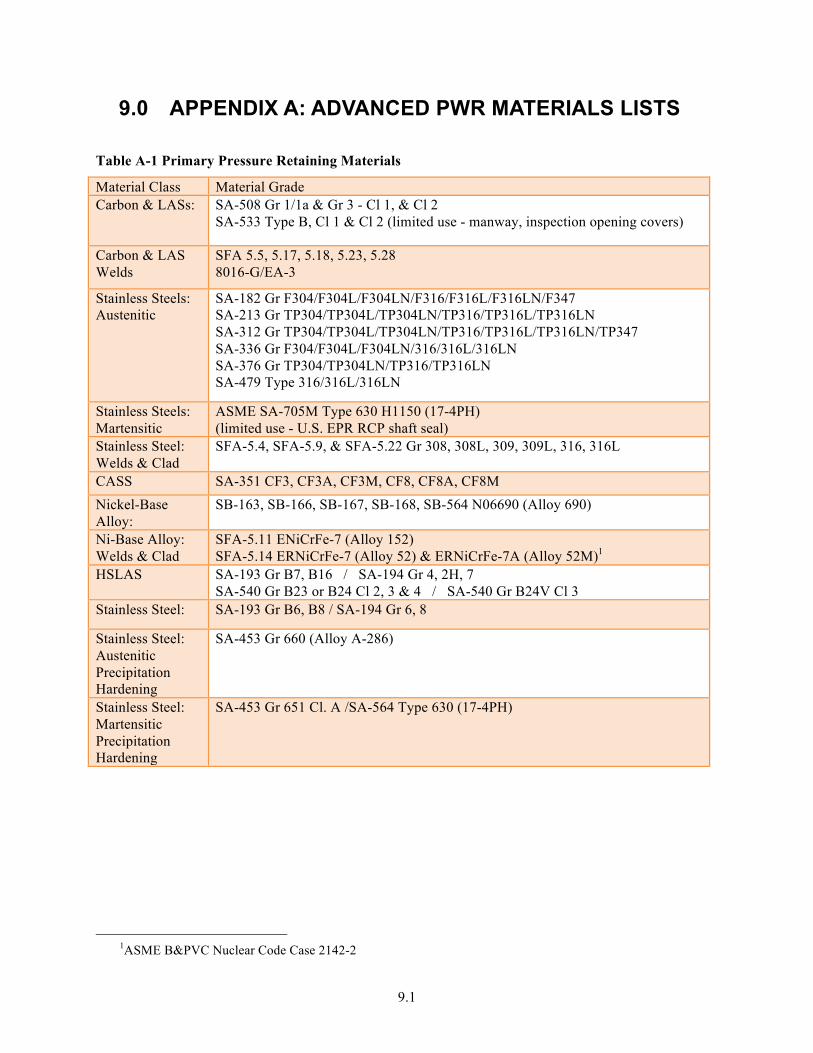
9.1
9.0 APPENDIX A: ADVANCED PWR MATERIALS LISTS
Table A-1 Primary Pressure Retaining Materials
Material Class Material Grade Carbon & LASs: SA-508 Gr 1/1a & Gr 3 - Cl 1, & Cl 2
SA-533 Type B, Cl 1 & Cl 2 (limited use - manway, inspection opening covers)
Carbon & LAS Welds
SFA 5.5, 5.17, 5.18, 5.23, 5.28 8016-G/EA-3
Stainless Steels: Austenitic
SA-182 Gr F304/F304L/F304LN/F316/F316L/F316LN/F347 SA-213 Gr TP304/TP304L/TP304LN/TP316/TP316L/TP316LN SA-312 Gr TP304/TP304L/TP304LN/TP316/TP316L/TP316LN/TP347 SA-336 Gr F304/F304L/F304LN/316/316L/316LN SA-376 Gr TP304/TP304LN/TP316/TP316LN SA-479 Type 316/316L/316LN
Stainless Steels: Martensitic
ASME SA-705M Type 630 H1150 (17-4PH) (limited use - U.S. EPR RCP shaft seal)
Stainless Steel: Welds & Clad
SFA-5.4, SFA-5.9, & SFA-5.22 Gr 308, 308L, 309, 309L, 316, 316L
CASS SA-351 CF3, CF3A, CF3M, CF8, CF8A, CF8M Nickel-Base Alloy:
SB-163, SB-166, SB-167, SB-168, SB-564 N06690 (Alloy 690)
Ni-Base Alloy: Welds & Clad
SFA-5.11 ENiCrFe-7 (Alloy 152) SFA-5.14 ERNiCrFe-7 (Alloy 52) & ERNiCrFe-7A (Alloy 52M)1
HSLAS SA-193 Gr B7, B16 / SA-194 Gr 4, 2H, 7 SA-540 Gr B23 or B24 Cl 2, 3 & 4 / SA-540 Gr B24V Cl 3
Stainless Steel: SA-193 Gr B6, B8 / SA-194 Gr 6, 8
Stainless Steel: Austenitic Precipitation Hardening
SA-453 Gr 660 (Alloy A-286)
Stainless Steel: Martensitic Precipitation Hardening
SA-453 Gr 651 Cl. A /SA-564 Type 630 (17-4PH)
1ASME B&PVC Nuclear Code Case 2142-2
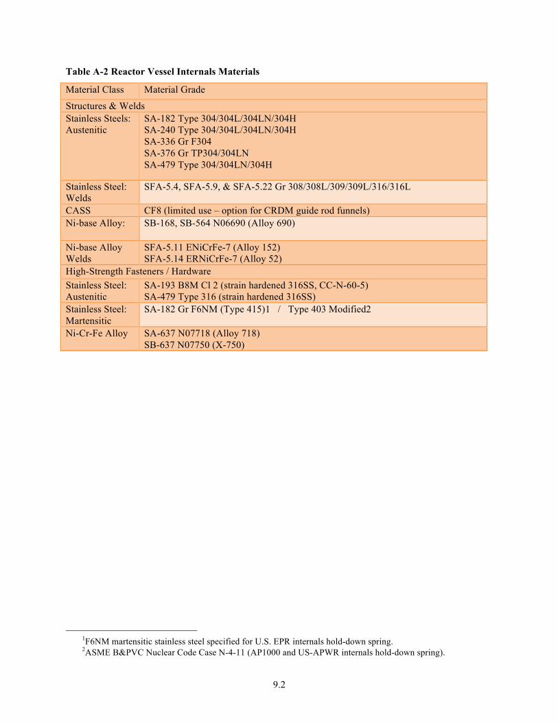
9.2
Table A-2 Reactor Vessel Internals Materials
Material Class Material Grade
Structures & Welds Stainless Steels: Austenitic
SA-182 Type 304/304L/304LN/304H SA-240 Type 304/304L/304LN/304H SA-336 Gr F304 SA-376 Gr TP304/304LN SA-479 Type 304/304LN/304H
Stainless Steel: Welds
SFA-5.4, SFA-5.9, & SFA-5.22 Gr 308/308L/309/309L/316/316L
CASS CF8 (limited use – option for CRDM guide rod funnels) Ni-base Alloy: SB-168, SB-564 N06690 (Alloy 690)
Ni-base Alloy Welds
SFA-5.11 ENiCrFe-7 (Alloy 152) SFA-5.14 ERNiCrFe-7 (Alloy 52)
High-Strength Fasteners / Hardware Stainless Steel: Austenitic
SA-193 B8M Cl 2 (strain hardened 316SS, CC-N-60-5) SA-479 Type 316 (strain hardened 316SS)
Stainless Steel: Martensitic
SA-182 Gr F6NM (Type 415)1 / Type 403 Modified2
Ni-Cr-Fe Alloy SA-637 N07718 (Alloy 718) SB-637 N07750 (X-750)
1F6NM martensitic stainless steel specified for U.S. EPR internals hold-down spring. 2ASME B&PVC Nuclear Code Case N-4-11 (AP1000 and US-APWR internals hold-down spring).
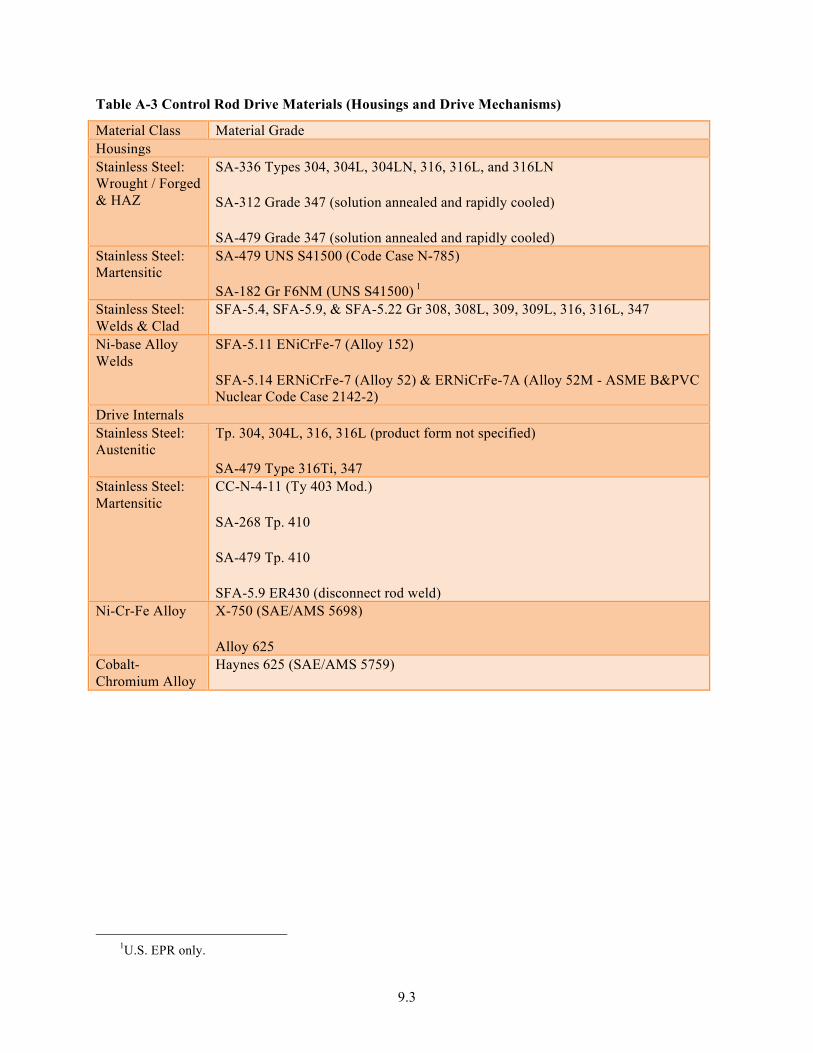
9.3
Table A-3 Control Rod Drive Materials (Housings and Drive Mechanisms)
Material Class Material Grade Housings Stainless Steel: Wrought / Forged & HAZ
SA-336 Types 304, 304L, 304LN, 316, 316L, and 316LN
SA-312 Grade 347 (solution annealed and rapidly cooled)
SA-479 Grade 347 (solution annealed and rapidly cooled) Stainless Steel: Martensitic
SA-479 UNS S41500 (Code Case N-785)
SA-182 Gr F6NM (UNS S41500) 1 Stainless Steel: Welds & Clad
SFA-5.4, SFA-5.9, & SFA-5.22 Gr 308, 308L, 309, 309L, 316, 316L, 347
Ni-base Alloy Welds
SFA-5.11 ENiCrFe-7 (Alloy 152)
SFA-5.14 ERNiCrFe-7 (Alloy 52) & ERNiCrFe-7A (Alloy 52M - ASME B&PVC Nuclear Code Case 2142-2)
Drive Internals Stainless Steel: Austenitic
Tp. 304, 304L, 316, 316L (product form not specified)
SA-479 Type 316Ti, 347 Stainless Steel: Martensitic
CC-N-4-11 (Ty 403 Mod.)
SA-268 Tp. 410
SA-479 Tp. 410
SFA-5.9 ER430 (disconnect rod weld) Ni-Cr-Fe Alloy X-750 (SAE/AMS 5698)
Alloy 625 Cobalt-Chromium Alloy
Haynes 625 (SAE/AMS 5759)
1U.S. EPR only.

9.4
Table A-4 Steam Generator Materials
Material Class Material Grade
Carbon Steel SA-36 SA-105 & SA-106 Gr B SA-234 WPB SA-285 Gr C SA-508 Gr 1A SA-516 Gr 60 &70
Low-Alloy Steel SA-234 P11& WP11 (Piping Components) SA-335 Gr P11 & P22 SA-387 Gr 12 Cl 1 & Gr P22 SA-508 Gr 3 Cl 2 A-517 Gr B SA-739 Gr B11 & B22
Carbon & Low-Alloy Steel Welds
SFA 5.5, 5.17, 5.18, 5.23, 5.28
SS: SA-240 UNS S40500, S40900 and UNS 41000 SA-479 UNS S40500 Type 316 & 316L
SS: Austenitic-Welds & Clad
SFA-5.4, SFA-5.9, & SFA-5.22 – 316, 316L
Ni-base Alloy: SB-163, N06690 (Alloy 690) (Feedwater Spargers, Blowdown Piping, Steam flow restrictor)
Ni-base Alloy Welds & Clad
SFA-5.11 ENiCrFe-7 (Alloy 152) SFA-5.14 ERNiCrFe-7 (Alloy 52) & ERNiCrFe-7A (Alloy 52M - ASME B&PVC Nuclear Code Case 2142-2)
PNNL-22290
Distribution
No. of No. of Copies Copies
Wayne Lunceford (PDF) Dave Sandusky (PDF)
mPower Hongqing Xu (PDF)
NuScale Daniel Ingersoll (PDF)
Local Distribution Pacific Northwest National Laboratory
SM Bruemmer (PDF) MA Catalan (PDF)