Embed Size (px)
Citation preview
1
Assessment of risk factors affecting
mechanical stress on the adjacent
segments after lumbar fusion
Ho-Joong Kim
Department of Medicine
The Graduate School, Yonsei University
2
Assessment of risk factors affecting
mechanical stress on the adjacent
segments after lumbar fusion
Directed by Professor Hwan-Mo Lee
The Doctoral Dissertation
submitted to the Department of Medicine,
the Graduate School of Yonsei University
in partial fulfillment of the requirements for the degree
of Doctor of Philosophy
Ho-Joong Kim
June 2010
3
This certifies that the Doctoral
Dissertation of Ho-Joong Kim is
approved.
------------------------------------
Thesis Supervisor : Hwan-Mo Lee
------------------------------------ (Thesis Committee Member#1)
------------------------------------
(Thesis Committee Member#2)
------------------------------------ (Thesis Committee Member#3)
------------------------------------
(Thesis Committee Member#4)
The Graduate School
Yonsei University
June 2010
4
ACKNOWLEDGEMENTS
First and foremost, I am heartily thankful to my supervisor, professor
Hwan-Mo Lee for the valuable guidance and advice. He has been
inspired me greatly to work in spine research. His willingness to motivate
me contributed tremendously to this study.
Besides, I would like to acknowledge thesis committee members,
professor Kwan-Chul Tark, professor Hwal Suh, professor Heoung-Jae
Chun, professor Seong-Hwan Moon who provided me valuable
information as the guidance of this study. Also, I would like to take this
opportunity to thank Department of Orthopaedic surgery in Yonsei
University College of Medicine and the Intelligent Structure & Integrated
Design Laboratory of School of Mechanical engineering in Yonsei
University for providing me with a good environment and facilities in
performing this study. It gave me an opportunity to participate and learn
about the spine biomechanics related researches. In addition, I would also
like to thank Kyoung-Tak Kang for his devoted work related with this
study.
Finally, I would like to thank my wife, son, parents and parents-in-law
for their understandings and supports on me in completing this study.
Especially, this study is dedicated to the memory of my father, YD Kim.
Without helps of the particular that mentioned above, I would face many
difficulties while doing this study.
5
<TABLE OF CONTENTS>
ABSTRACT ····································································· 1
I. INTRODUCTION ···························································· 3
II. MATERIALS AND METHODS ··········································· 4
1. Finite element (FE) model ··············································· 4
2. Material properties ························································ 6
3. Simulation of preservation of PLC (Pp) and
Sacrifice of PLC (Sp) ··················································· 7
4. Simulation of instrumented posterolateral fusion (WiP) and
posterolateral fusion state without instruments (WoP) ············ 7
5. Boundary and loading conditions ······································· 8
III. RESULTS ·································································· 9
1. Model validation ·························································· 9
2. Comparison of range of motion (ROM) among models ············· 9
3. Changes of disc stress in 4 fusion models ····························· 11
IV. DISCUSSION ······························································ 12
V. CONCLUSION ····························································· 15
REFERENCES ································································· 15
ABSTRACT(IN KOREAN) ················································· 18
PUBLICATION LIST ························································ 20
6
LIST OF FIGURES
Figure 1. The four FE (finite element) models in the current
study ··································································· 5
Figure 2. The comparison between the current intact model and a
previous study ························································ 9
Figure 3. The percent change of the ROM at each corresponding
segment among the four fusion models ·························· 10
Figure 4. The comparison of the percent change of maximal von
Mises stress of the intervertebral disc at each corresponding
segment in the four models ········································ 11
LIST OF TABLES
Table 1. Material properties in the present FE models ·········· 6
1
ABSTRACT
Assessment of risk factors affecting mechanical stress on the adjacent
segments after lumbar fusion
Ho-Joong Kim
Department of Medicine
The Graduate School, Yonsei University
(Directed by Professor Hwan-Mo Lee)
Introduction. The ablation of proximal posterior ligament complex (PLC)
continuity and the presence of pedicle screws have been reported to
affect the biomechanics at adjacent segments after lumbar fusion.
However, there have been few studies regarding the quantitative
assessment of their contribution to overstress at adjacent segments after
lumbar fusion. Therefore, the purpose of this study is to investigate the
changes in the disc stress and range of motion (ROM) at adjacent
segments after lumbar fusion based on the presence of pedicle screws or
the preservation of the proximal PLC.
Methods. In the validated intact lumbar finite element model including
L2 through L5, four types of L3-4 fusion models were simulated. These
models included the preservation of the PLC continuity with pedicle
screws (Pp WiP), the preservation of PLC continuity without pedicle
screws (Pp WoP), the sacrifice of PLC with pedicle screws (Sp WiP),
and the sacrifice of PLC without pedicle screws (Sp WoP). In each
scenario, the ROM and maximal von Mises stress of discs at adjacent
segments were analyzed under 4 pure moments.
Results. Among the 4 models, the Sp WiP yielded the greatest increase in
the ROM and the maximal von Mises stress of the disc at adjacent
segments under four moments. Following the SP WiP, the order of
increase of the ROM and the disc stress was Pp WiP, Sp WoP, and Pp
WoP. Furthermore, the increase of ROM and disc stress at the proximal
adjacent segment was more than at the distal adjacent segment under all
2
4 moments in each model.
Conclusions. The current study suggests that the preservation of the PLC
continuity or the removal of pedicle screws after complete fusion could
decrease the stress at adjacent segments, and their combination could act
synergistically.
----------------------------------------------------------------------------------------
Key words : lumbar fusion, adjacent segment degeneration, pedicle
screws, posterior ligament complex, finite element model
3
Assessment of risk factors affecting mechanical stress on the adjacent
segments after lumbar fusion
Ho-Joong Kim
Department of Medicine
The Graduate School, Yonsei University
(Directed by Professor Hwan-Mo Lee)
I. INTRODUCTION
Adjacent segment degeneration (ASD) is one of the troublesome sequelae
following spinal fusion surgery,1-3
and has become more widespread with the
increase of spinal fusions performed in recent years.3 Even though there have been
conflicting results,4-6
many biomechanical studies have shown that the fusion
process could impose significant amounts of disc stress and increased motion at
the adjacent segment.1,2,7,8
The potential risk factors for ASD have been investigated and were found to
include instrumentation, posterior lumbar interbody fusion, injury to the facet joint
of the adjacent segment, fusion length, age, and sagittal alignment.2,7,9
However,
the actual significance of these risk factors still remains uncertain and
controversial. These divergent views on the risk factors of ASD may be due to
different patient populations and methodologies.2 Even though fusion affects the
motion and disc stress of the adjacent segment, there are significant questions that
remain. To what extent does each risk factor impact ASD? Are there interactions
among the risk factors on ASD?
In order to answer these questions, we investigated the stress and the range of
motion (ROM) at adjacent segments after fusion, using a finite element (FE)
model of the lumbar spine. Two important risk factors were chosen. They were the
4
instrumentation (pedicle screws) and the ablation of proximal posterior ligament
complex (PLC). Therefore, the purpose of this study was to investigate the
changes of the disc stress and ROM at adjacent segments after lumbar fusion
according to whether pedicle screws are removed or not, and whether the
continuity of the proximal PLC is preserved or not.
II. MATERIALS AND METHODS
1. Finite element model
A 3-dimensional (3D) nonlinear FE model of the lumbar spine that consisted of
four lumbar vertebrae, three intervertebral discs, and associated spinal ligaments
was developed. Geometrical details of the human lumbar spine (L2-L5) were
obtained from high-resolution CT images of a forty six-year-old male subject who
had no spinal deformities. Digital CT data were imported to a software program
(Mimics; Materialise Inc., Leuven, Belgium) that was used to generate the
3-dimensional geometrical surface of the lumbar spine. The exported IGES files
from the Mimics software were input into Unigraphics NX 3.0 (Siemens PLM
Software, Torrance, CA, USA) to form solid models for each vertebral segment.
The solid model was then imported into Hypermesh 8.0 (Altair Engineering, Inc.,
Troy, MI, USA) to generate FE meshes. The FE method was analyzed with
commercially available software (ABAQUS 6.6-1; Hibbitt, Karlsson and Sorenson,
Inc., Providence, RI, USA).
Three-dimensional isotropic solid elements were used for modeling the cortical
and cancellous cores, the posterior bony parts of the vertebrae. The anterior
longitudinal ligament, posterior longitudinal ligament, intertransverse ligament,
ligament flavum, capsular ligament, interspinous ligament, and supraspinous
ligament were modeled using tension-only truss elements. Three-dimensional
surface-to-surface contact was used to simulate the interaction between the
articulating surfaces of facet joints. The cartilaginous layer between the facet
surfaces was simulated by ABAQUS’s “softened contact” parameter, which
exponentially adjusted force transfer across the joint. The initial gap between
5
articulating surfaces was based on CT images.
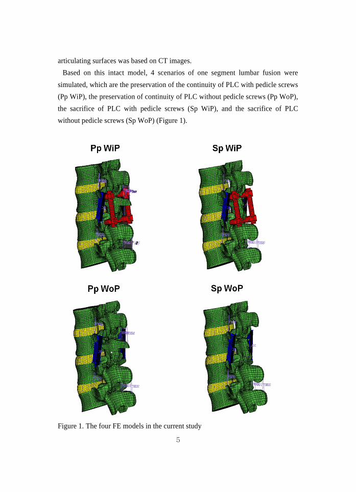
Based on this intact model, 4 scenarios of one segment lumbar fusion were
simulated, which are the preservation of the continuity of PLC with pedicle screws
(Pp WiP), the preservation of continuity of PLC without pedicle screws (Pp WoP),
the sacrifice of PLC with pedicle screws (Sp WiP), and the sacrifice of PLC
without pedicle screws (Sp WoP) (Figure 1).
Figure 1. The four FE models in the current study
6
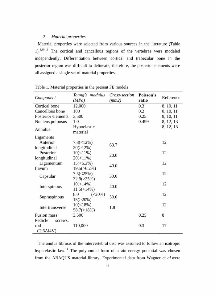
2. Material properties
Material properties were selected from various sources in the literature (Table
1).8,10-13
The cortical and cancellous regions of the vertebrae were modeled
independently. Differentiation between cortical and trabecular bone in the
posterior region was difficult to delineate; therefore, the posterior elements were
all assigned a single set of material properties.
Table 1. Material properties in the present FE models
Component Young’s modulus
(MPa)
Cross-section
(mm2) Poisson’s
ratio Reference
Cortical bone 12,000 0.3 8, 10, 11
Cancellous bone 100 0.2 8, 10, 11
Posterior elements 3,500 0.25 8, 10, 11
Nucleus pulposus 1.0 0.499 8, 12, 13
Annulus Hypoelastic
material
8, 12, 13
Ligaments
Anterior
longitudinal
7.8(<12%)
20(>12%) 63.7
12
Posterior
longitudinal
10(<11%)
20(>11%) 20.0
12
Ligamentum
flavum
15(<6.2%)
19.5(>6.2%) 40.0
12
Capsular 7.5(<25%)
32.9(>25%) 30.0
12
Interspinous 10(<14%)
11.6(>14%) 40.0
12
Supraspinous 8.0 (<20%)
15(>20%) 30.0
12
Intertransverse 10(<18%)
58.7(>18%) 1.8
12
Fusion mass 3,500 0.25 8
Pedicle screws,
rod
(Ti6Al4V)
110,000 0.3 17
The anulus fibrosis of the intervertebral disc was assumed to follow an isotropic
hyperelastic law.14
The polynomial form of strain energy potential was chosen
from the ABAQUS material library. Experimental data from Wagner et al were
7
used.15
The nucleus pulposus was modeled as nearly incompressible. Spinal
ligaments were represented by nonlinear material properties. Naturally changing
ligament stiffness (initially low stiffness at low strains, followed by increasing
stiffness at higher strains) was simulated through the “hypoelastic” material
designation (Table 1). Three- dimensional truss elements were used to simulate
ligaments, which were active only in tension.
3. Simulation of preservation of PLC (Pp) and Sacrifice of PLC (Sp)
In order to simulate the decompression state, a supraspinous ligament and
interspinous ligament between L3 and L4 spinous processes were removed along
with partial removal of L3 and L4 spinous processes. Furthermore, the inferior
portion of L3 lamina, and ligamentum flavum of L3-4 were removed. The Pp
model has the continuity of the proximal PLC between the L2 spinous process and
the remained L3 spinous process, while the L3 spinous process and PLC between
L2 and L3 were totally removed in the Sp model.
4. Simulation of instrumented posterolateral fusion (WiP) and
posterolateral fusion state without instruments (WoP)
The WiP model simulated the scenario of the instrumented posterolateral fusion.
First, posterolateral fusion was represented as bilateral rectangular columns of
fusion mass between the posterior surfaces of the transverse processes of L3 and
L4. The volume of each posterolateral fusion mass was 15 mm x 40 mm x 5 mm
(3.0 cm3) (Figure 1), and the material property of the fusion mass was identical to
the posterior element of the vertebral body. This was consistent with the previous
clinical measures by Ha et al.16
No motion was permitted between the fusion mass
and transverse processes at the fused sites. This would parallel the clinical
situation in that there would be no interface motion with a solid fusion.
A posterior pedicle screw fixation was added to the L3-4 posterolateral fusion.
All screws had a sharp thread to prevent relative motion at the bone-screw
interface. Except for the screw tip, the remaining surface of the screw was fixed to
the bone without allowing relative motion. A “tie” contact condition was used,
8
which enabled the screw threads and vertebrae to be bonded together permanently
by full constraint. The diameter of all pedicle screws was assumed to be 5.0 mm,
the mean diameter of 6.5 mm outer diameter (including thread height) of real
screws. The length of the screws was 40 mm in L3 and L4. The screws were
inserted into the pedicles of L3 and L4. Insertion of the screws was in a horizontal
direction with inward inclination of 10 degrees. The rods were 5.5 mm in diameter.
All instruments were made of titanium alloy (Ti6Al4V).17
The simulation of the WoP model, which represented the clinical scenario of the
posterolateral fusion state with removal of pedicle screws after fusion achievement,
was made by removal of the pedicle screws and rods of the previous WiP model.
5. Boundary and loading conditions
This FE investigation included two types of loading conditions corresponding to
loads used in the experimental part of the study18
for model validation and model
predictions for clinically relevant loading scenarios. Validation included loading
the model with 10 Nm of moments. The nodes of the inferior surfaces of the
inferior-most vertebral body were completely fixed in all directions. To validate
the model, the same loading conditions used in the Yamamoto et al’s study were
applied.18
Nodes on top of the L2 vertebra were defined as the coupling nodes. A
reference node was created and connected to all coupling nodes. A coupling
element was, thus, created to distribute moments on the reference node. Therefore,
10 Nm flexion, 10 Nm extension, 10 Nm torsion, and 10 Nm lateral bending
moment under the 150 N preload were imposed on the L2 vertebral body,
respectively. To reach 10 Nm moments, the five load steps were applied to three
models.
The second type of loading condition was a hybrid testing protocol, which was
implemented during the flexibility testing of the FE models as described by Goel
et al19
for the study of adjacent level biomechanics (ROM and maximal Von mises
stress of the disc). This protocol involved the applied pure moment for the intact
and four fusion models until its L2–L5 rotation (displacement) equaled the intact
load control case values.
9
III. RESULTS
1. Model validation
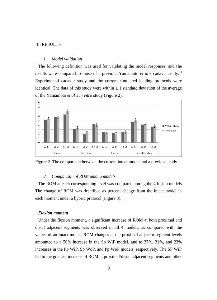
The following definition was used for validating the model responses, and the
results were compared to those of a previous Yamamoto et al’s cadaver study.18
Experimental cadaver study and the current simulated loading protocols were
identical. The data of this study were within ± 1 standard deviation of the average
of the Yamamoto et al’s in vitro study (Figure 2).
Figure 2. The comparison between the current intact model and a previous study
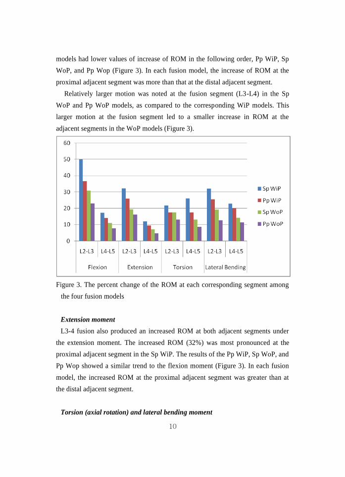
2. Comparison of ROM among models
The ROM at each corresponding level was compared among the 4 fusion models.
The change of ROM was described as percent change from the intact model in
each moment under a hybrid protocol (Figure 3).
Flexion moment
Under the flexion moment, a significant increase of ROM at both proximal and
distal adjacent segments was observed in all 4 models, as compared with the
values of an intact model. ROM changes at the proximal adjacent segment levels
amounted to a 50% increase in the Sp WiP model, and to 37%, 31%, and 23%
increases in the Pp WiP, Sp WoP, and Pp WoP models, respectively. The SP WiP
led to the greatest increase of ROM at proximal/distal adjacent segments and other
10
models had lower values of increase of ROM in the following order, Pp WiP, Sp
WoP, and Pp Wop (Figure 3). In each fusion model, the increase of ROM at the
proximal adjacent segment was more than that at the distal adjacent segment.
Relatively larger motion was noted at the fusion segment (L3-L4) in the Sp
WoP and Pp WoP models, as compared to the corresponding WiP models. This
larger motion at the fusion segment led to a smaller increase in ROM at the
adjacent segments in the WoP models (Figure 3).
Figure 3. The percent change of the ROM at each corresponding segment among
the four fusion models
Extension moment
L3-4 fusion also produced an increased ROM at both adjacent segments under
the extension moment. The increased ROM (32%) was most pronounced at the
proximal adjacent segment in the Sp WiP. The results of the Pp WiP, Sp WoP, and
Pp Wop showed a similar trend to the flexion moment (Figure 3). In each fusion
model, the increased ROM at the proximal adjacent segment was greater than at
the distal adjacent segment.
Torsion (axial rotation) and lateral bending moment
11
Similar patterns of ROM changes at adjacent segments were also noted under
torsion (axial rotation) and the lateral bending moment (Figure 3). The increased
ROM at adjacent segments was most prominent in the Sp WiP model.
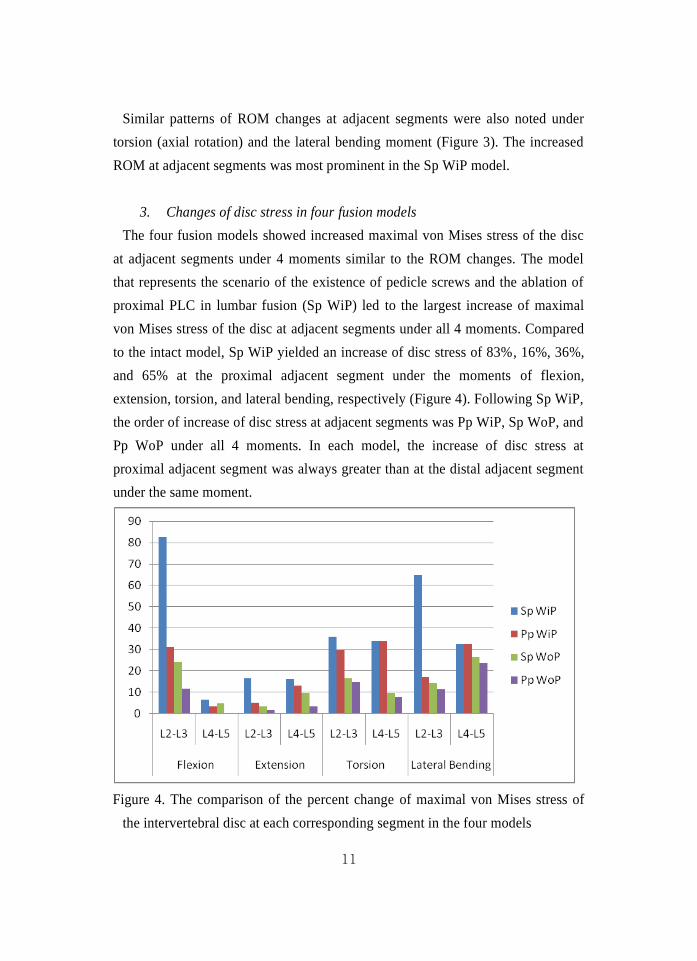
3. Changes of disc stress in four fusion models
The four fusion models showed increased maximal von Mises stress of the disc
at adjacent segments under 4 moments similar to the ROM changes. The model
that represents the scenario of the existence of pedicle screws and the ablation of
proximal PLC in lumbar fusion (Sp WiP) led to the largest increase of maximal
von Mises stress of the disc at adjacent segments under all 4 moments. Compared
to the intact model, Sp WiP yielded an increase of disc stress of 83%, 16%, 36%,
and 65% at the proximal adjacent segment under the moments of flexion,
extension, torsion, and lateral bending, respectively (Figure 4). Following Sp WiP,
the order of increase of disc stress at adjacent segments was Pp WiP, Sp WoP, and
Pp WoP under all 4 moments. In each model, the increase of disc stress at
proximal adjacent segment was always greater than at the distal adjacent segment
under the same moment.
Figure 4. The comparison of the percent change of maximal von Mises stress of
the intervertebral disc at each corresponding segment in the four models
12
IV. DISCUSSION
Many risk factors about ASD have been reported, including instrumentation,
lumbar interbody fusion, injury to the facet joint of the adjacent segment, fusion
length, age, sagittal alignment, and previous arthritic changes at the adjacent facet
joint.1-3,9,20
Authors chose to evaluate the presence of pedicle screw and the
preservation of PLC, because their significance has not yet been fully determined.
Four FE models were used in the present study. The Sp WiP model included both
risk factors (the ablation of PLC and existence of pedicle screws), while the Sp
WoP model and Pp WiP models included only one risk factor of the ablation of
PLC and the presence of pedicle screws, respectively. The Pp WoP model
represented the fusion model having neither of two risk factors.
As expected, the ablation of PLC with disruption of proximal segment continuity,
simulated in Sp WiP and Sp WoP models, caused a greater ROM increase at
adjacent segments, compared to the Pp WiP and Pp WoP models. These results are
consistent with a previous clinical study, in which the group without PLC
preservation showed adjacent instability in more cases than the control group with
PLC preservation.21
Moreover, Cardoso et al have reported that the complete
laminectomy without PLC preservation significantly increased adjacent level
flexion/extension ROM.22
Even though the partial or total removal of the posterior
element, including the lamina, facet joints, and PLC may be necessary for
complete decompression procedures, preservation of the PLC continuity with
proximal adjacent segment is paramount to prevent overstress at the proximal
adjacent segment, especially in instrumented lumbar arthrodesis.
This study also demonstrated that the pedicle screw fixation created greater
mechanical stress at adjacent segments even after fusion. Conversely, in the Pp
WoP and Sp WoP models that simulated the scenario of pedicle screw removal,
relatively more motion was allowed at the fusion segment (L3-4) under 4 moments.
The simultaneously compensatory motion and disc stress were reduced at the
adjacent segments, as compared to corresponding WiP models. This is explained
by the decrease of stiffness of fusion segments resulting from the removal of
13
pedicle screws. These findings are also in line with our previous in vivo study in
which non-instrumented fusion had less ROM at adjacent segments on the
dynamogram than instrumented fusion.9 Moreover, the ROM at the fusion
segment in the Sp WoP and Pp Wop models is consistent with the results of a
previous study in which residual motion of the fusion segment was 2° to 3°.23
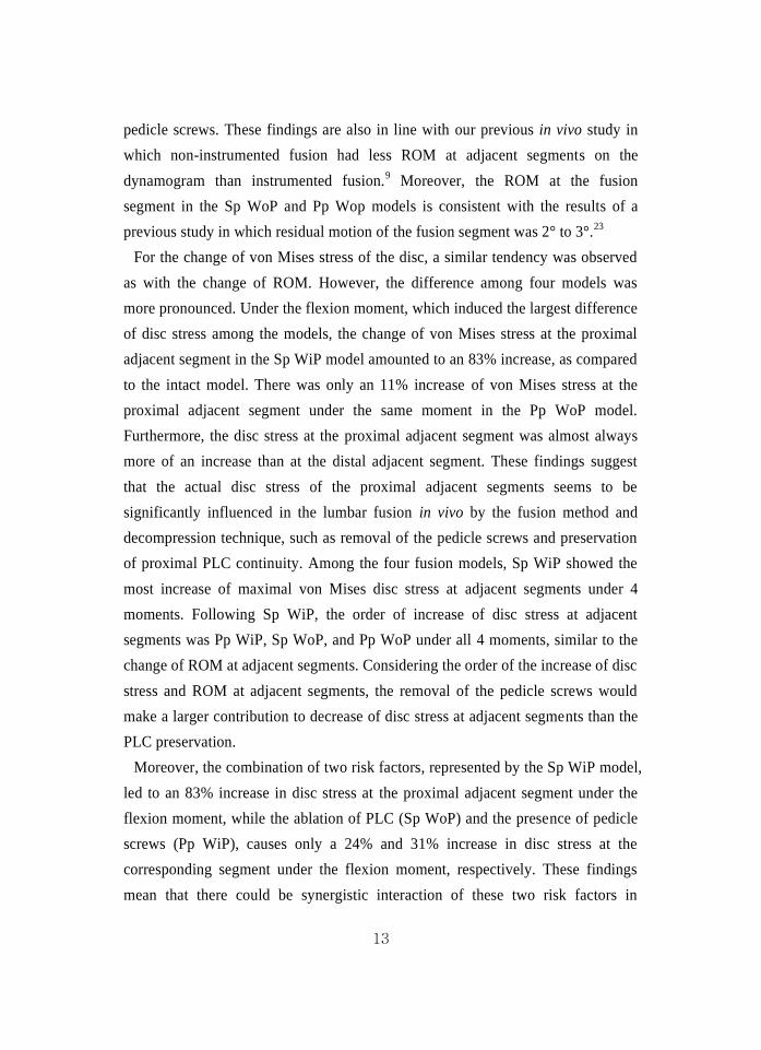
For the change of von Mises stress of the disc, a similar tendency was observed
as with the change of ROM. However, the difference among four models was
more pronounced. Under the flexion moment, which induced the largest difference
of disc stress among the models, the change of von Mises stress at the proximal
adjacent segment in the Sp WiP model amounted to an 83% increase, as compared
to the intact model. There was only an 11% increase of von Mises stress at the
proximal adjacent segment under the same moment in the Pp WoP model.
Furthermore, the disc stress at the proximal adjacent segment was almost always
more of an increase than at the distal adjacent segment. These findings suggest
that the actual disc stress of the proximal adjacent segments seems to be
significantly influenced in the lumbar fusion in vivo by the fusion method and
decompression technique, such as removal of the pedicle screws and preservation
of proximal PLC continuity. Among the four fusion models, Sp WiP showed the
most increase of maximal von Mises disc stress at adjacent segments under 4
moments. Following Sp WiP, the order of increase of disc stress at adjacent
segments was Pp WiP, Sp WoP, and Pp WoP under all 4 moments, similar to the
change of ROM at adjacent segments. Considering the order of the increase of disc
stress and ROM at adjacent segments, the removal of the pedicle screws would
make a larger contribution to decrease of disc stress at adjacent segments than the
PLC preservation.
Moreover, the combination of two risk factors, represented by the Sp WiP model,
led to an 83% increase in disc stress at the proximal adjacent segment under the
flexion moment, while the ablation of PLC (Sp WoP) and the presence of pedicle
screws (Pp WiP), causes only a 24% and 31% increase in disc stress at the
corresponding segment under the flexion moment, respectively. These findings
mean that there could be synergistic interaction of these two risk factors in
14
increasing the disc stress at adjacent segments following lumbar fusion. This
phenomenon was also noted under other moments. In the extension moment, the
Sp WiP model caused a 16% increase in disc stress at the proximal adjacent
segment, while the Pp WiP and Sp WoP models produced a 5% and 3% increase
in disc stress, respectively, at the corresponding segment. Furthermore, in the
lateral bending moment, the Sp WiP model showed a 65% increase in disc stress
at the proximal adjacent segment. The Pp WiP and Sp WoP models produced a
17% and 14% increase in disc stress, respectively, at the proximal adjacent
segment. These results suggest that the overstress of adjacent segments can be
reduced synergistically if these two risk factors would be simultaneously
controlled in the lumbar fusion in vivo.
It is acknowledged that this study has certain limitations. First, the simulations
were performed only under four moments. However, loading conditions are more
complex in the lumbar spine in vivo. Second, we did not simulate lumbar spine
muscles in the current FE model. In the in vivo state, back muscles might have
significant influence on the biomechanical perspective. Third, in spine fusion in
vivo, the stiffness and shape of the fusion mass is not constant. Even though we
assumed the specific shape of the fusion mass and the material properties, the
ROM at the fusion segment in the WoP models is similar to that of a previous in
vivo study and an FE study.9,23
Therefore, the results from the present FE models
could demonstrate a trend similar to that of the clinical findings.
From many previous studies, the fusion itself seems to lead to increased stress at
adjacent segments and be a main factor of ASD.1,2
However, the current study
suggests that fusion would not only be a cause of ASD, but the decompression
procedure, that is the ablation of PLC, could also be a significant factor leading to
increased stress at a proximal adjacent segment. Furthermore, the instrumentation
also imposed an additional stress on adjacent segments due to increased stiffness.
The combination of these two risk factors produced the synergistically adverse
effect on the stress of adjacent discs.
15
V. CONCLUSION
This study demonstrates that the pedicle screws and the injury of continuity of
proximal PLC could produce adverse effects on the disc stress of adjacent
segments, and interact synergistically. However, future study is necessary to
determine the clinical significance. Additionally other in vivo biomechanical
studies should precede clinical application.
REFERENCES
1. Lee CK. Accelerated degeneration of the segment adjacent to a lumbar
fusion. Spine 1988;13:375-7.
2. Park P, Garton HJ, Gala VC, Hoff JT, McGillicuddy JE. Adjacent
segment disease after lumbar or lumbosacral fusion: review of the
literature. Spine 2004;29:1938-44.
3. Harrop JS, Youssef JA, Maltenfort M, Vorwald P, Jabbour P, Bono CM,
et al. Lumbar adjacent segment degeneration and disease after
arthrodesis and total disc arthroplasty. Spine 2008;33:1701-7.
4. Penta M, Sandhu A, Fraser RD. Magnetic resonance imaging assessment
of disc degeneration 10 years after anterior lumbar interbody fusion.
Spine 1995;20:743-7.
5. Wai EK, Santos ER, Morcom RA, Fraser RD. Magnetic resonance
imaging 20 years after anterior lumbar interbody fusion. Spine
2006;31:1952-6.
6. Pellis F, Hernndez A, Vidal X, Minguell J, Martnez C, Villanueva C.
Radiologic assessment of all unfused lumbar segments 7.5 years after
instrumented posterior spinal fusion. Spine 2007;32:574-9.
7. Shono Y, Kaneda K, Abumi K, McAfee PC, Cunningham BW. Stability
of posterior spinal instrumentation and its effects on adjacent motion
segments in the lumbosacral spine. Spine 1998;23:1550-8.
8. Chen CS, Cheng CK, Liu CL, Lo WH. Stress analysis of the disc
16
adjacent to interbody fusion in lumbar spine. Med Eng Phys
2001;23:483-91.
9. Kim HJ, Moon SH, Chun HJ, Kang KT, Kim HS, Moon ES, et al.
Comparison of mechanical motion profiles following instrumented
fusion and non-instrumented fusion at the L4-5 segment. Clin Invest
Med 2009;32:E64-9.
10. Goel VK, Kim YE, Lim TH, Weinstein JN. An analytical investigation
of the mechanics of spinal instrumentation. Spine 1988;13:1003-11.
11. Shirazi-Adl SA, Shrivastava SC, Ahmed AM. Stress analysis of the
lumbar disc-body unit in compression. A three-dimensional nonlinear
finite element study. Spine 1984;9:120-34.
12. Pintar FA, Yoganandan N, Myers T, Elhagediab A, Sances A.
Biomechanical properties of human lumbar spine ligaments. J Biomech
1992;25:1351-6.
13. Wu HC, Yao RF. Mechanical behavior of the human annulus fibrosus. J
Biomech 1976;9:1-7.
14. Guan Y, Yoganandan N, Zhang J, Pintar FA, Cusick JF, Wolfla CE, et al.
Validation of a clinical finite element model of the human lumbosacral
spine. Med Biol Eng Comput 2006;44:633-41.
15. Wagner DR, Lotz JC. Theoretical model and experimental results for the
nonlinear elastic behavior of human annulus fibrosus. J Orthop Res
2004;22:901-9.
16. Ha K, Lee J, Kim K. Bone graft volumetric changes and clinical
outcomes after instrumented lumbar or lumbosacral fusion: a
prospective cohort study with a five-year follow-up. Spine
2009;34:1663-8.
17. Kim Y. Finite element analysis of anterior lumbar interbody fusion:
threaded cylindrical cage and pedicle screw fixation. Spine
2007;32:2558-68.
18. Yamamoto I, Panjabi MM, Crisco T, Oxland T. Three-dimensional
movements of the whole lumbar spine and lumbosacral joint. Spine
17
1989;14:1256-60.
19. Goel VK, Grauer JN, Patel T, Biyani A, Sairyo K, Vishnubhotla S, et al.
Effects of charité artificial disc on the implanted and adjacent spinal
segments mechanics using a hybrid testing protocol. Spine
2005;30:2755-64.
20. Kumar MN, Baklanov A, Chopin D. Correlation between sagittal plane
changes and adjacent segment degeneration following lumbar spine
fusion. Eur Spine J 2001;10:314-9.
21. Lai P, Chen L, Niu C, Fu T, Chen W. Relation between laminectomy and
development of adjacent segment instability after lumbar fusion with
pedicle fixation. Spine 2004;29:2527-32; discussion 32.
22. Cardoso MJ, Dmitriev AE, Helgeson M, Lehman RA, Kuklo TR, Rosner
MK. Does superior-segment facet violation or laminectomy destabilize
the adjacent level in lumbar transpedicular fixation? An in vitro human
cadaveric assessment. Spine 2008;33:2868-73.
23. Bono CM, Khandha A, Vadapalli S, Holekamp S, Goel VK, Garfin SR.
Residual sagittal motion after lumbar fusion: a finite element analysis
with implications on radiographic flexion-extension criteria. Spine
2007;32:417-22.
18
ABSTRACT (In Korean)
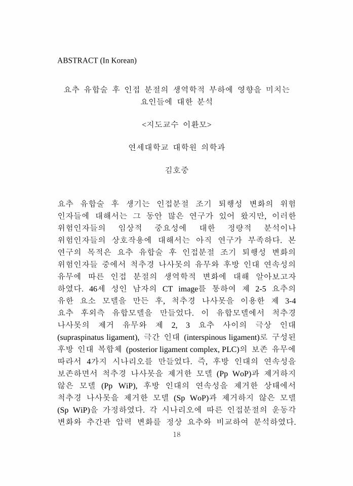
요추 유합술 후 인접 분절의 생역학적 부하에 영향을 미치는
요인들에 대한 분석
<지도교수 이환모>
연세대학교 대학원 의학과
김호중
요추 유합술 후 생기는 인접분절 조기 퇴행성 변화의 위험
인자들에 대해서는 그 동안 많은 연구가 있어 왔지만, 이러한
위험인자들의 임상적 중요성에 대한 정량적 분석이나
위험인자들의 상호작용에 대해서는 아직 연구가 부족하다. 본
연구의 목적은 요추 유합술 후 인접분절 조기 퇴행성 변화의
위험인자들 중에서 척추경 나사못의 유무와 후방 인대 연속성의
유무에 따른 인접 분절의 생역학적 변화에 대해 알아보고자
하였다. 46세 성인 남자의 CT image를 통하여 제 2-5 요추의
유한 요소 모델을 만든 후, 척추경 나사못을 이용한 제 3-4
요추 후외측 유합모델을 만들었다. 이 유합모델에서 척추경
나사못의 제거 유무와 제 2, 3 요추 사이의 극상 인대
(supraspinatus ligament), 극간 인대 (interspinous ligament)로 구성된
후방 인대 복합체 (posterior ligament complex, PLC)의 보존 유무에
따라서 4가지 시나리오를 만들었다. 즉, 후방 인대의 연속성을
보존하면서 척추경 나사못을 제거한 모델 (Pp WoP)과 제거하지
않은 모델 (Pp WiP), 후방 인대의 연속성을 제거한 상태에서
척추경 나사못을 제거한 모델 (Sp WoP)과 제거하지 않은 모델
(Sp WiP)을 가정하였다. 각 시나리오에 따른 인접분절의 운동각
변화와 추간판 압력 변화를 정상 요추와 비교하여 분석하였다.
19
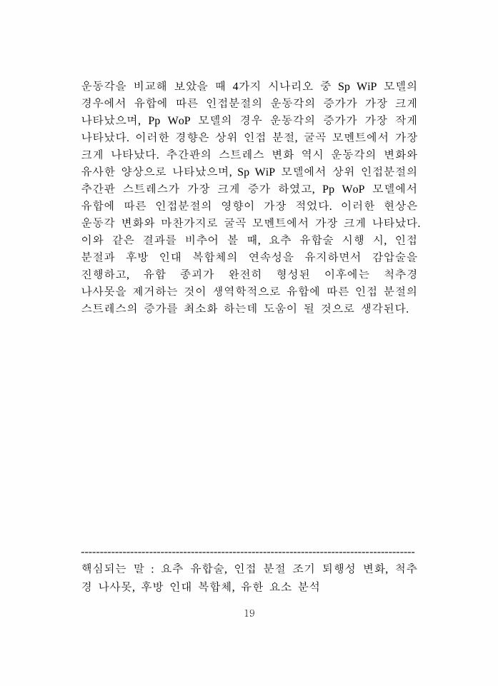
운동각을 비교해 보았을 때 4가지 시나리오 중 Sp WiP 모델의
경우에서 유합에 따른 인접분절의 운동각의 증가가 가장 크게
나타났으며, Pp WoP 모델의 경우 운동각의 증가가 가장 작게
나타났다. 이러한 경향은 상위 인접 분절, 굴곡 모멘트에서 가장
크게 나타났다. 추간판의 스트레스 변화 역시 운동각의 변화와
유사한 양상으로 나타났으며, Sp WiP 모델에서 상위 인접분절의
추간판 스트레스가 가장 크게 증가 하였고, Pp WoP 모델에서
유합에 따른 인접분절의 영향이 가장 적었다. 이러한 현상은
운동각 변화와 마찬가지로 굴곡 모멘트에서 가장 크게 나타났다.
이와 같은 결과를 비추어 볼 때, 요추 유합술 시행 시, 인접
분절과 후방 인대 복합체의 연속성을 유지하면서 감압술을
진행하고, 유합 종괴가 완전히 형성된 이후에는 척추경
나사못을 제거하는 것이 생역학적으로 유합에 따른 인접 분절의
스트레스의 증가를 최소화 하는데 도움이 될 것으로 생각된다.
----------------------------------------------------------------------------------------
핵심되는 말 : 요추 유합술, 인접 분절 조기 퇴행성 변화, 척추
경 나사못, 후방 인대 복합체, 유한 요소 분석
20
PUBLICATION LIST
1. Kim HJ, Moon SH, Chun HJ, Kang KT, Kim HS, Moon ES, et al.
Comparison of mechanical motion profiles following
instrumented fusion and non-instrumented fusion at the L4-5
segment. Clin Invest Med 2009;32:E64-9
2. Kim HJ, Chun HJ, Moon SH, Kang KT, Kim HS, Moon ES, et al.
Analysis of biomechanical changes after removal of
instrumentation in lumbar arthrodesis by finite element analysis.
Med Biol Eng Comput (in press)