Embed Size (px)
Citation preview

Page | 1
Assessment of Technical Requirements for Deploying Off-grid Power Solutions in Health Centers in Nagaland

Page | 2
Assessment of Technical Requirements for Deploying Off-grid Power Solutions in Health Centers in Nagaland
TABLE OF CONTENTS
List of Tables .......................................................................................................................................... 5
List of Figures ......................................................................................................................................... 6
Glossary .................................................................................................................................................. 7
Preface ................................................................................................................................................... 9
Executive Summary .............................................................................................................................. 10
Background .......................................................................................................................................... 12
Energy Requirements ........................................................................................................................... 17
Load Segments ................................................................................................................................. 17
Characteristics of Load Categories .................................................................................................. 21
Category of loads at the Health Centers Considered for Solar PV Backup ...................................... 21
Assessment of Critical Connected Load ....................................................................................... 21
Energy Management Considerations for System Design ............................................................ 22
Other Design Requisites ................................................................................................................... 23
Load Considerations for Different Type of Health Centers ............................................................. 24
Feasible Solar Installation Capacity Based on Available Area ......................................................... 25
Technical Design .................................................................................................................................. 27
Introduction ..................................................................................................................................... 27
Scenario 1 .................................................................................................................................... 27
Scenario 2 .................................................................................................................................... 27
Scenario 3 .................................................................................................................................... 28
Scenario 4 .................................................................................................................................... 28
Scenario 5 .................................................................................................................................... 29
Meteorological and Solar Data ........................................................................................................ 30
Indicative Technical Parameters ...................................................................................................... 31

Page | 3
Assessment of Technical Requirements for Deploying Off-grid Power Solutions in Health Centers in Nagaland
Solar Photovoltaic Module .......................................................................................................... 31
Module Mounting Structure ........................................................................................................ 31
DC Side Equipment ...................................................................................................................... 32
Power Conditioning Unit Including Inverters .............................................................................. 32
Battery Banks ............................................................................................................................... 34
Performance (Efficiency) Matrix ...................................................................................................... 36
Losses in PV Solar systems ........................................................................................................... 37
Reflection Losses ......................................................................................................................... 37
Soiling........................................................................................................................................... 37
Mismatch Effects ......................................................................................................................... 38
Maximum Power Point Tracking (MPPT) Losses ......................................................................... 38
Inverter Efficiency ........................................................................................................................ 38
Solar Plant Design ........................................................................................................................ 38
Mounting Position ....................................................................................................................... 39
Inclination Angle .......................................................................................................................... 39
Module Degradation Due to Aging .............................................................................................. 39
DC-to-AC Derate Factor ............................................................................................................... 39
Derate Factors for AC Power Rating at STC ................................................................................. 39
System Design .................................................................................................................................. 40
SLDs of the Designed Proposed Solar Power Generation Systems for Nagaland Health Centres
..................................................................................................................................................... 41
CAPITAL COST ESTIMATION ................................................................................................................. 49
Operation and Maintenance of solar power system ........................................................................... 50
Scheduled Maintenance .............................................................................................................. 51
Unscheduled Maintenance .......................................................................................................... 51

Page | 4
Assessment of Technical Requirements for Deploying Off-grid Power Solutions in Health Centers in Nagaland
Operation and Maintenance Procedure ...................................................................................... 51
Maintenance and Care ................................................................................................................ 52
Condition of Roof where Solar Power System has been Installed .............................................. 52
Spare Parts Management ............................................................................................................ 53

Page | 5
Assessment of Technical Requirements for Deploying Off-grid Power Solutions in Health Centers in Nagaland
LIST OF TABLES
Table 1: Utility Power Scenario in Nagaland ........................................................................................ 13
Table 2: Type of Equipment Considered for Calculating Solar PV Supported Emergency Electrical
System .................................................................................................................................................. 18
Table 3: Connected Critical Load Considered for Solar PV Hybrid Support in District Health Centre &
Community Health Centres .................................................................................................................. 21
Table 4: Connected Critical Load Considered for Solar PV Support in Primary Health Centres & Sub
Centres ................................................................................................................................................. 22
Table 6: Final Loads Considered for Each Type of Health Centres ...................................................... 24
Table 7: A Projection of Installed Capacity as per Land/Roof Area Available for Solar Project in
Surveyed Health Centres and Health Centres ..................................................................................... 25
Table 8: Recommendations for the Pilot Project ................................................................................. 26
Table 9: Proposed Solar Power Generation System ............................................................................ 30
Table 10: Daily Solar Insolation ............................................................................................................ 30
Table 11: Monthly and Averaged Annual Solar Insolation .................................................................. 30
Table 12: The Technical Parameters of PV Modules ........................................................................... 31
Table 13: Type of PCUs Considered for Systems to be Installed at Sub Centres and Primary Health
Centres ................................................................................................................................................. 33
Table 14: Type of PCUs Considered for Systems to be Installed at Community Health Centres and
District Health Centres ......................................................................................................................... 34
Table 15: Battery Banks Considered for Each of the Solar PV Power Generation Systems ................ 35
Table 16: Derate Factors for AC Power Rating .................................................................................... 39
Table 17: Final System Designed Size and Configuration .................................................................... 40
Table 18: Capital Cost Estimation for the Proposed Solar PV Power Generation Systems in District
Health Centre and Community Health Centres ...................................... Error! Bookmark not defined.
Table 19: Capital Cost Estimation for the Proposed Solar PV Power Generation Systems in Primary
Health Centres and Sub-Centres ............................................................. Error! Bookmark not defined.
Table 20: Maintenance Schedule ......................................................................................................... 51

Page | 6
Assessment of Technical Requirements for Deploying Off-grid Power Solutions in Health Centers in Nagaland
LIST OF FIGURES
Figure 1: Population Coverage under each Health Centre in Nagaland .............................................. 12
Figure 2: Electricity Availability in Health Centres across Nagaland .................................................... 13
Figure 3: Total Connected Loads in DHCs in Surveyed Health Centres ............................................... 13
Figure 4: Total Connected Loads in CHCs in Surveyed Health Centres ................................................ 14
Figure 5: Total Connected Loads in PHCs in Surveyed Health Centres ................................................ 14
Figure 6: Total Connected Loads in Sub Centres in Surveyed Health Centres .................................... 15
Figure 7: Technical Design- Scenario 1 ................................................................................................ 27
Figure 8: Technical Design- Scenario 2 ................................................................................................ 28
Figure 9: Technical Design- Scenario 3 ................................................................................................ 28
Figure 10: Technical Design- Scenario 4 .............................................................................................. 29
Figure 11: Technical Design- Scenario 5 .............................................................................................. 29
Figure 12: Technical Design for DHC System Type-1 ........................................................................... 41
Figure 13: Technical Design for DHC System Type-2 ........................................................................... 42
Figure 14: Technical Design for CHC System Type-1 ............................................................................ 43
Figure 15: Technical Design for CHC System Type-2 ............................................................................ 44
Figure 16: Technical Design for PHC System Type-1 ............................................................................ 45
Figure 17: Technical Design for PHC System Type-2 ............................................................................ 46
Figure 18: Technical Design for Sub Centre System Type-1 ................................................................ 47
Figure 19: Technical Design for Sub Centre System Type-2 ................................................................ 48

Page | 7
Assessment of Technical Requirements for Deploying Off-grid Power Solutions in Health Centers in Nagaland
GLOSSARY
Alternating Current (AC) - An electric current in which the direction of flow
oscillates at frequent, regular intervals.
Amp - A measure of electrical current flow.
Battery - A device that stores energy and makes it available in an
electrical
Capital Cost - The initial cost to purchase and install equipment.
Charge Controller - Controls the flow of current to and from the battery to
protect from over charging or over discharging.
Cold Storage
- System of equipment that attempts to keep vaccines
and blood at proper temperatures as they are
distributed from the manufacturer or supplier to the
locations where they are administered.
Direct Current (DC) - An electric current flowing in one direction.
Durability - The typical system lifetime, expressed either in years or
(for engine generators) in hours of run-time.
Electricity - Energy made available by the flow of electric charge
through a conductor.
Energy - The capacity of a physical system to do work. The units
of energy are kilowatt-hour or joules.
Grid
- The network of transmission lines, distribution lines, and
transformers used in central power systems.
Insolation
- The amount of sunlight falling on an area over the
course of a year, often measured in watts per square
meter.
Inverter - A solid state device that produces an AC output from a
DC input.
Kilowatt (kW) - One thousand watts.

Page | 8
Assessment of Technical Requirements for Deploying Off-grid Power Solutions in Health Centers in Nagaland
Kilowatt Hour (kWh) - The work performed by one kilowatt of electric power in
one hour.
Load - The amount of electric power or energy delivered or
required at any specified point or points on a system.
Operating Cost
- The day-to-day expense of using and maintaining
property.
Photovoltaic (PV) System - The production of electricity from sunlight commonly
referred to as “solar electric”.
Power - The rate of doing work; measured in watts.
Renewable Energy
- Energy derived from non-fossil fuel resources, includes
energy produced from PV, wind turbines, hydro electric
and biomass.
Solar Electric – See
photovoltaic system
- See photovoltaic system.
Volt, Voltage (V) - A unit of electrical force or electric pressure.
Watt, Wattage (W) - A unit of power equal to one joule per second. Watts =
volts x amps.
Yield – Output - The quantity of something that is created (usually within
a given period of time).

Page | 9
Assessment of Technical Requirements for Deploying Off-grid Power Solutions in Health Centers in Nagaland
PREFACE
The National Rural Health Mission (NRHM) was launched with the aim to provide for an accessible, affordable, acceptable and accountable health care through a functional public health system. It also aims to expedite achievements of policy goals set under the National Health Policy and the Millennium Development Goals. The key features, in order to achieve the goals of the Mission, include making the public health delivery system fully functional and accountable to the community, human resources management, community involvement, decentralization, rigorous monitoring & evaluation against standards, convergence of health and related programmes from village level and upwards, innovations and flexible financing and also interventions for improving the health indicators. The mission has led to the formation of India Public Health Standards (IPHS) for various levels of health centers namely – District Health Centers (DHC), Community Health Centers (CHC), Primary Health Centers (PHC) and Sub-Centers (SC) – which are upgraded regularly; such standards are used as reference for planning and up-gradation of public health care infrastructure. The norms are designed to ensure strengthening of infrastructure facilities such as essential equipment, supply of essential drugs & consumable, availability of uninterrupted power supply, construction of buildings, storage facilities (refrigerators), etc. Each of these centers is designated to cater a specific band of facilities and populace:
SC and PHC provide basic services such as immunization, basic curative & preventive
services, maternal and child health services with a small population coverage. Observing
the pattern of resource utilization in these two types of health centers, it can stated that
the primary usage of electricity is for two purposes only – Refrigeration and
Illumination.
CHC and DHC is established to cater to larger communities (towns/villages) in a district
and hence planned to have centralized facilities providing secondary referral level
treatments. In addition to the facilities offered by PHC and SC, CHCs and DHCs also
provide diagnostic and therapeutic services, laboratory (and testing) services and super-
specialty services for high risk diseases such as pulmonary ailments, HIV, cancer etc.
These health centres also need to be ready for epidemic and disaster management at all
times. The electrical demand for such centres is much higher and diverse than SC & PHC,
both in terms of energy (due to presence high power equipment such as X-ray, CT scan,
and MRI etc.) and quality of supply (to be able to undertake critical procedures at any
given time).

Page | 10
Assessment of Technical Requirements for Deploying Off-grid Power Solutions in Health Centers in Nagaland
EXECUTIVE SUMMARY
This report provides a technical assessment for deploying Off-Grid Solar Power to improve Health Service Delivery in Nagaland, as part of World Bank’s Health Nutrition and Population (HNP) Technical Assistance to North Eastern States. A detailed assessment was carried out based on field survey of 24 health centers across 4 districts of Nagaland, to determine the status, gaps and needs assessment of the energy situation in the identified health centers. The objective of this report is to define and recommend the technical requirements, design imperatives and planning investments required to provide appropriate solar power back-up for the health centers. Nagaland has a population of approximately two million, an estimated infant mortality rate of 21 per 1,000 (2011), an estimated maternal mortality ratio of 240 per 100,000 births (2007), and an estimated 39% of under-five children are malnourished (stunted) (2005-06). An assessment of the health centers revealed a direct connection between deficient supplies of quality power with a deficient delivery of health services. The connected load, location and patient footfall in the 24 health centers were studied to assess the shortfall which could be met by installation of solar hybrid power back up system. Further benchmarking against equipment, infrastructure and facilities as outlined by the Indian Public Health Standards (IPHS) revealed that none of the centers met the standard requirements that would fulfill these parameters. Solar power, if tailored to meet the fluctuating demands of the health centers can provide reliable, affordable, clean and de-centralized power supply. Based on a collaborative consultation with World Bank and the Directorate of Health Services & Family Welfare (Govt. of Nagaland), the emergency load requirements were categorized into 4 groups of load combinations – Base load and Critical load 1, 2, 3, thus leading to two types of solar system design for each category of health center. A detailed load assessment has been carried out to determine various types of load levels across different categories of health centers as well as load characteristics of various equipment types and corresponding health services. For example, the District Health Centers have a higher load requirement for each of the categories since these centers handle medical emergencies and more complex, super-specialty and life saving procedures. It has been surmised that energy management by means of minimizing phantom loads (stand-by load) and energy saving settings for all types of equipment, primarily imaging equipment, are important considerations for optimization of the solar power system. Various other design considerations include RF noise, continuous power demand of critical load etc. Power failure in a health centre would result in life threatening conditions for patients undergoing surgery or on life support, i.e. procedures that are reliant on a consistent power supply. Hence, the battery backup power to critical equipment has been incorporated in the design to sustain the critical supply for a reasonable period of time. Battery banks provide additional power during surges created by large medical imaging equipment. A PV Syst software base analysis has been carried out for each of the system configuration, considering the mean of the meteorological and solar data spectrum available for Nagaland.

Page | 11
Assessment of Technical Requirements for Deploying Off-grid Power Solutions in Health Centers in Nagaland
In general, renewable energy options (e.g., photovoltaic (PV) system, in this case) will have higher capital costs than diesel or other fuel-based electricity generating options. However, over the long-term, solar PV systems will have lower operating costs and produce no emissions. However, battery maintenance, occasional cleaning, and theft-prevention will be the recurring costs. A hybrid system using a solar PV system and a traditional diesel generator will have a higher up-front capital cost than a renewable-only system; but shall provide greater flexibility, including the ability for one system to support the other. For illustrative purposes, a PV/diesel hybrid is represented in report below. Indicative capital cost estimation for battery backup solar PV system has also been provided for each of the recommended models. However, it is to be noted that actual price at a specific location may vary considerably from the figures presented in the report. In order to ensure a smooth interface between the proposed solar power installation and the existing electrical circuit, it may be required to undertake partial re-wiring of the current electricity distribution network within the specific health center. For the same purpose certain retro-fit equipment may also be required to enable manual/semi F automatic power management systems. It may be stated that such re-wiring or retro-fits will not have any major cost implication to the project. The exact requirement can only be evaluated and thereafter defined during the actual installation work. Health centers and hospitals are also a major hot water consumer and the demand is round the year. The predominant way of heating is individual geysers in operation theaters, wards etc. Major consumption of hot water in health centres is for bathing of patients and their attendants in wards, hand washing and sterilization of equipment in operation theatre and kitchen purposes. The power supply scenario in the urban areas is unsatisfactory and, considering the demography, cost of electricity is as high. In view of these observations, installation of solar water heaters has been proposed for the identified health centers.

Page | 12
Assessment of Technical Requirements for Deploying Off-grid Power Solutions in Health Centers in Nagaland
BACKGROUND
Currently, Nagaland has a total of 554 public health centers with 396 SCs, 125 PHCs, 21 CHCs and 11 DHCs. While, SC and PHC serve as the first point of contact with community (offering services such as medical consulting, family welfare, vaccination, etc.), CHCs and DHCs serve to deliver critical health services (such as surgeries, diagnostic services, specialty consulting, treatment of high risk ailments, etc.). Also, while the SC and PHC are evenly distributed across the state, CHC and DHC are located in comparatively developed towns of a district, and hence, cater to a larger population. Figure 1 provides details of population coverage under each health centers and is benchmarked against IPHS standard (shown as horizontal line for each health center).
Figure 1: Population Coverage under each Health Centre in Nagaland
As per Central Electric Authority (CEA), Ministry of Power, power requirement in Nagaland in the concurrent period of 2013-2014 would jump to at least 125MW from the current demand (2012) of 80-110MW. As on March 2012, Nagaland has only a small unpredictable hydro peak power generation capacity of 28.67 MW1. Further, about 382 villages in Nagaland are yet to be electrified as on August 2013.
1 Energy Statistics-2013-book by MINISTRY OF STATISTICS AND PROGRAMME IMPLEMENTATION GOVERNMENT OF
INDIA
10
80
00
51
00
0 7
10
00
13
60
00
48
00
0
81
00
0
68
00
0
69
00
0
98
00
0
0
95
00
0
27
00
0
11
00
0
15
00
0
18
00
0
60
00
14
00
0
11
00
0
11
00
0
25
00
0
39
00
0
12
00
0
5000 4000 4000 5000 3000 4000 4000 3000 5000
15000
6000
0
20,000
40,000
60,000
80,000
100,000
120,000
140,000
CHC DHC SC

Page | 13
Assessment of Technical Requirements for Deploying Off-grid Power Solutions in Health Centers in Nagaland
Table 1: Utility Power Scenario in Nagaland2
State Energy demand in MU Peak load demand in MW
Requirement Available Deficit Requirement Available Deficit
Nagaland 591 558 -33(-5.6%) 125 114 -11(-8.8%)
Therefore, the state has frequent load shedding, with health centers observing long power outages. As shown in Figure 2, of the 24 health centers3 surveyed, at least 18 of them observe power outages of above 18 hours per day.
Figure 2: Electricity Availability in Health Centres across Nagaland
The survey indicated that the current loads available at the health centres were far below the required standards across medical procedures as prescribed by the IPHS. The load pattern summary shown in the Figures below demonstrate a severe shortfall particularly in equipment and connected load.
Figure 3: Total Connected Loads in DHCs in Surveyed Health Centres
2 Source-http://www.cea.nic.in/reports/yearly/lgbr_report.pdf
3 The survey was carried out for 3 district DHC, 3 CHCs, 9 PHCs and 9 SCs, located in four districts- Mokokchung,
Kohima, Wokha and Tuensang.
1
18
5
Less than 6 hours 6 hours to 12 hours 12 hours to 18 hours

Page | 14
Assessment of Technical Requirements for Deploying Off-grid Power Solutions in Health Centers in Nagaland
Figure 4: Total Connected Loads in CHCs in Surveyed Health Centres
Figure 5: Total Connected Loads in PHCs in Surveyed Health Centres
28
.84
14
.77
10
.92
9.4
1
32
7.9
5
16
3.3
9
78
.37
99
.39
35
7
17
8.1
6
89
.28
10
8.8
0
100
200
300
400
IPHS Standard Mokokchung DHC Tuensang DHC Wokha DHC
Load
(in
kW
)
Total connected illumination load at 415 V 3PH, AC supply (in kW)
Total connected equipment load at 415 V 3PH, AC supply (in kW)
Total connected load at 415 V 3PH, AC supply (in kW)
7.7
2
3.7
2
3.7
3
1.8
5
42
.53
11
.37
23
.43
20
.76
50
.25
15
.09
27
.16
22
.61
0
10
20
30
40
50
60
IPHS Standard Changtongya CHC Noklak CHC Longkhim CHC
Load
(in
kW
)
Total connected illumination load (in kW) Total connected equipment load (in kW)
Total connected electrical load (in kW)

Page | 15
Assessment of Technical Requirements for Deploying Off-grid Power Solutions in Health Centers in Nagaland
Figure 6: Total Connected Loads in Sub Centres in Surveyed Health Centres
Based on the above figures, it may be concluded that there is lack4 of medical equipment and illumination infrastructure across health centres in Nagaland. The above trend is partially due to lack of reliable power availability to health centres in Nagaland. For example, in Tuensang District, while the DHC has CT scan machine installed for last 5 years, it has never been used as
4 Details of equipment for each health center can be referred in Annexure II, III and IV.
2.1
1
3.1
6
1.2
2.5
5
2.0
5
1.3
2
0.7
7
1.2
7
0.6
6
11
.82
14
.6
6.4
1
5.1
5
5.1
1
3.8
5
2.9
1
3.3
2
2.1
2.7
5
13
.93
18
8
8
8
6
5
5
4
4
02468
101214161820
Load
(in
kW
)
Total connected illumination load Total connected equipment load
Total connected electrical load
0.3
8
0.1
6
0.1
8
0.1
6
0.4
1
0.1
1
0.2
8
0.1
8
0.2
0.1
3
0.2
2
2.7
1
1.4
6
0.2
0.1
0.2
0.1
0.2
0.2
0
0.2
1.0
5
3.0
9
1.6
2
0.4
0.3
0.7
0.3
0.5
0.4
0.2
0.4
1.3
0
0.5
1
1.5
2
2.5
3
3.5
Load
(in
kW
)
Total connected illumination load Total connected equipment load
Total connected electrical load

Page | 16
Assessment of Technical Requirements for Deploying Off-grid Power Solutions in Health Centers in Nagaland
there was lack of quality of power (and uncertainty of availability of power) in the Health Centre.

Page | 17
Assessment of Technical Requirements for Deploying Off-grid Power Solutions in Health Centers in Nagaland
ENERGY REQUIREMENTS
In health centers, poor infrastructure leads to poor delivery quality of health services and an unreliable energy source further adds to such challenges. Lack of readily available and assured supply of energy, impedes the efforts of the state government to upgrade the infrastructure and facilities of the health centers. Currently, each health center covers the gap in energy requirements through Diesel- only during extremely critical activities such as surgeries, and inverter/battery system is installed for cold storage. However, such energy sources are either high in operational cost or unreliable in case of large outages. In order to meet the critical and urgent requirements of assured, affordable and universal access to health services, particularly in the far reaches of districts in Nagaland, it is imperative that the current energy deficits be met using solar energy, which was identified as the sustainable energy source appropriate for mitigating the challenges inherent in operating a health center in Nagaland5.
Load Segments
On analyzing energy systems and electrical loads of various health facilities in Nagaland, a need to divide loads into different levels based on their medical significance arose, so as to facilitate sound management of energy. Further, each load has a unique demand with respect to quality of power required, for instance some loads can endure minor voltage fluctuations, while some cannot. Hence, to develop a sustainable solution aiming to provide an un-interrupted supply, a detailed load assessment was carried out to categorize loads considering all the stated factors. As an outcome, loads were categorized into two groups across different categories of health centres based on collaborative consultation with World Bank and the Directorate of Health Services and Family Welfare (Govt. of Nagaland). Following are the categories:
1. Non-critical loads: Loads which do not pose immediate risk to patients or substantially disrupt facility operation in case of no power supply. Equipments such as room heaters, air conditioners and similar peripheral equipments are categorized under ‘Non-critical loads’.
2. Critical loads: Loads which are critical in operations of a health facility, such as lighting, laboratory equipment, emergency and operating rooms, information systems and computers are categorized under ‘Critical Loads’. Critical loads are further categorized by their need for high-quality, uninterrupted power:
Contact critical loads: Loads which can endure minor fluctuations in voltage and brief loss of power are categorized under ‘Contact critical loads’. Loads in this category can include lighting or vaccination refrigeration and some labor room equipment.
No-contact critical loads: Loads for which any interruption in power will result in damage to the equipment or loss of data are categorized under ‘No-contact
5 Kindly refer to technical assessment report for the analysis between various alternate power sources.

Page | 18
Assessment of Technical Requirements for Deploying Off-grid Power Solutions in Health Centers in Nagaland
critical loads’. Loads in this category can include sensitive laboratory instruments, medical equipment such as x-rays, and data acquisition systems.
An identification of every facility's total load as contact or no-contact load is made to envisage the backup solar PV power system for an uninterruptible power supply sized to cover all essential no-contact loads. Under the real life scenario it is unlikely that all electrical equipment at a health facility will be turned on at the same time. It is generally observed that different equipment operate at different times of the day. During health facility's normal operating hours (usually between 10am- 5pm), the load profile shows higher total loads, because computers, lab equipment and other devices are being used at the same time. In the evening (usually after 5pm), or during off-peak hours, loads are reduced because the facility is supporting less activity. To provide quality health service under above stated- varied power requirement situations, and load analysis it is essential that power support system with degree of reliability, durability, maintainability, efficiency, and economy as appropriate are developed such that minimum emergency un-interrupted power supply for following types of equipment/facility are maintained in each type of health center: Further, an assessment was carried out to determine the required load levels across types of health centers. As it is evident from table below, DHCs have a much higher requirement of critical load (level 1 and 2) as they cater to health emergencies and life saving procedures such as child birth, neo-natal care, cardiac incidents etc.
Table 2: Type of Equipment Considered for Calculating Solar PV Supported Emergency Electrical System
DH Type I & Type II CHC Type I & Type II PHC Type I & Type II Sub Centres Cat-A Cat-B
Base Load:
Emergency lighting load (about 40% of total lighting load)
Emergency lighting load (about 35% of total lighting load)
Emergency lighting load 8 No’s 36 W CFL
3 No’s 22 W CFL
Administrative load (80% of total load including Teaching)
Comp+Xerox+FAX+TV Administrative load (Refrigerator, Computer, Modem)
Mobile charger 7 DTH
Pump and auxiliaries One small pump of 1/2 HP (0.375+overload of 30%)
Pump 200W & 50 W auxiliary) Pump 200W
Critical Load Level 1:
Blood bank, DF, ILR, Refrigerator & AC
Blood bank DF large & Refrigerator 200L
Blood bank DF large & Refrigerator
Small Refrigerator
OPD (only emergency load)
Slit Lamp Suction Syringe Needle Destroyer
Distant Vision Charts Otoscope
Dental Chair motorized
Air Rotor
Compressor oil free medical grade (noise-free)
Needle cutter/Hub cutter
Dental X-ray IOP/OPG X-ray viewer

Page | 19
Assessment of Technical Requirements for Deploying Off-grid Power Solutions in Health Centers in Nagaland
DH Type I & Type II CHC Type I & Type II PHC Type I & Type II Sub Centres Cat-A Cat-B
with LED light.
Labour room (Normal delivery)
Pulse Oxymeter baby & adult Incubator Water Heater (immersion) small immersion water heater
Baby Incubators Shadow less lamps for labour room
Suction machine
Radiant Warmer Resuscitator Oxygen generator
Vacuum extractor metal Laproscope Resuscitator
Suction Machine Infant radiant warmer-2 Infant radiant warmer-1
Cardiopulmonary Equipment
ECG machine computerized ECG ECG machine ordinary
ECG machine ordinary ECG machine ordinary
12 Channel stress ECG test equipment Tread Mill*
Cardiac Monitor with defibrillator 1
Echocardiography Machine Infusion pump 1
Cardiac Monitor Water Heater (immersion)
Cardiac Monitor with defibrillator Diathermy machine
Ventilators (Adult)
Ventilators (Pediatrics)
Pulse Oximeter
Pulse Oximeter with NIB.P*
Infusion pump
Incinerator and mortuary including waste management
Critical Load Level 2:
USG
Color Doppler Ultrasound machine with 4 probes: Abdomen, Pediatric, So. Parts and Intra-Cavitory Ultra Sonogram
Incubators Incubators Infant warmer (Only in Cat-A)
Portable ultrasound
Incubators
OT
Anesthesia Equipment Anesthesia Surgical cutter
Auto Clave HP Horizontal Lamps shadow less Shadow less lamps for labour room
Operation Table Hydraulic Major Sterilizer Anesthesia
Shadow less lamp ceiling type major* Suction pump
Sterilizer (Big instruments)
Computer+printer+UPS+TV, etc Computer, printer, communication system
Two Computer, printer, Fax Computer, printer
Critical Load Level 3:
Labour & SNCU ward advanced equipment

Page | 20
Assessment of Technical Requirements for Deploying Off-grid Power Solutions in Health Centers in Nagaland
DH Type I & Type II CHC Type I & Type II PHC Type I & Type II Sub Centres Cat-A Cat-B
Double Sided Blue Light Phototherapy
Water Heater (immersion) Photo therapy Unit
Pulse Oxymeter baby & adult Lamp for new born baby
Infusion pump or syringe pump
Cardiac monitor baby & adult
CFL Phototherapy
Phototherapy Unit
Cardio Toco Graphy Monitor
Nebulizer baby
Newborn Care Equipment
Suction Machine
Infantometer
Servo-controlled Radiant Warmer
Operation additional
Auto Clave HP Vertical (2 bin) Drum, sterilizing cylindrical - 275 mm Dia x 132 mm
Autoclave vertical single bin
Shadow less lamp ceiling type minor*
Sterilizer (Small instruments)
Bowl Sterilizer Medium
Diathermy Machine (Electric Cautery)
Suction Apparatus - Electrical
Dehumidifier*
Ultrasonic cutting and coagulation device
Laboratory
Electric microscope Bath, water, serological, with racks, cover, thermostat, 240 v
Lab Incubator Microscope, binocular
Electricentrifuge, table top-3 Illuminator
Blood gas analyser Microscope Microscope (Only in Cat-A)
Electrolyte Analyser Hematology
Laboratory Autoclaves Pathology
automatic blood gas analyzer-2 Serology
Blender Biochemistry
Hot Air oven Binocular Microscope with oil immersion
Table top centrifuge Table top centrifuge

Page | 21
Assessment of Technical Requirements for Deploying Off-grid Power Solutions in Health Centers in Nagaland
Characteristics of Load Categories
To proceed further with the categorization of loads (in levels of criticality), inputs from load assessment based on their characteristics (as shown below) is carried out. This can further support in sound management of energy and is required to envisage the solar PV power system. Following are characteristics of connected loads in health centres across Nagaland:
Resistive type: These equipments are mostly used in labour room, OPDs, operation theatre and in emergency mode. Majority of loads at the health center are of the resistive type. These include infant warmer, photo therapy unit, autoclave, sterilizers, heaters, boilers, etc. These loads are continuous and each of the equipment may remain plugged for continuous stretches of time as per requirement. Sum of all such loads range from 600–6000 Watt.
Inductive and Capacitive load (in combination): Include diagnostic equipments. The connected load of such equipment are usually <1,500 Watts.
Others: Highest connected load centres are in the imaging section, which consists of a combination of MRI, CT Scans and X-Ray machines. This unit normally draws the maximum energy and the connected load can range from 6 kW to 60 kW. It is to be noted that the typical energy consumption characteristic of these equipment are of short and intermittent usage but with very high draw of current.
Category of loads at the Health Centers Considered for Solar PV Backup
Following assessment of all stated factors (medical criticality and characteristics of load type), a final table has been prepared enlisting categories of loads in each of the health centres. The same will be used for designing for solar PV Solar PV hybrid power generation system.
Assessment of Critical Connected Load
Based on the above selection of equipment and facilities in each category of health centres the following loads are envisaged for installation of Solar PV hybrid power generation systems.
Table 3: Connected Critical Load Considered for Solar PV Hybrid Support in District Health Centre & Community Health Centres
Category of load
District Health Centres Community Health Centres
District Health Centres
similar to Mokokchung
(Type I)
District Health Centres
similar to Tuensang (Type II)
CHCs similar to Noklak Or Longkhim
with X-ray machine (Type I)
CHCs similar to Changtongya without X-ray
machine (Type II)
Base Load: 8.50 6.75 2.33 1.70
Total Critical Load Level 1 14.25 12.10 5.65 3.35
Total Critical Load Level 2 17.25 12.55 4.75 3.60
Total Critical Load Level 3 22.25 15.00 4.25 2.75
Estimated Max energy consumption in a day (kWh)
280 213 85 57

Page | 22
Assessment of Technical Requirements for Deploying Off-grid Power Solutions in Health Centers in Nagaland
Category of load
District Health Centres Community Health Centres
District Health Centres
similar to Mokokchung
(Type I)
District Health Centres
similar to Tuensang (Type II)
CHCs similar to Noklak Or Longkhim
with X-ray machine (Type I)
CHCs similar to Changtongya without X-ray
machine (Type II)
Total desired solar PV backed load (kW) 62.25 46.40 17.00 11.00
Table 4: Connected Critical Load Considered for Solar PV Support in Primary Health Centres & Sub Centres
Category of load
Primary Health Centres Sub Centres
Kuthur or having connected load of 8 kW or more
(Type I)
Jotsoma or having
connected load of 4 kW-6 kW
(Type II)
Category A Category B
Base Load: 0.80 0.60 0.36 0.06
(No pump)
Total Critical Load Level 1 3.19 2.64 1.20 0.95
Total Critical Load Level 2 1.65 0.85 0.85 0.10
Total Critical Load Level 3 0.40 0.30 0.03 0.0
Estimated Max energy consumption in a day (kWh)
33 25 14( 5.0
Total desired solar PV backed load (kW)
6.00 4.00 2.0 1.0
Energy Management Considerations for System Design Following are some major energy management considerations for system design:
Power Saving Measures:
1. Plug loads, or devices plugged into wall outlets, represent about 75 to 90 percent of total energy consumed by Nagaland health facilities. Many types of plug-in equipment consume energy even when turned off, accounting for “phantom” loads—also known as standby power or “leaking electricity.” Phantom loads can consume up to 5 percent of an electrical plug loads. Envisage: All health centres operate only during normal business hours (9am-5pm), its equipment is idle for nearly 16 hours every day. It is advisable that all District Health Centres, Community Health Centres be installed with Power strips (or auto/manual power management system) and/or Power-savers to help phantom (stand-by) load management by controlling monitors, computers, lights, and even some medical equipment, when such equipment are not in use.
2. Imaging equipment, such as an MRI machine or a CT scanner, typically represents the
largest single plug load. Medical devices such as patient monitors and EKGs are also

Page | 23
Assessment of Technical Requirements for Deploying Off-grid Power Solutions in Health Centers in Nagaland
major energy consumers because while they draw moderate amounts of power, they are used quite frequently. Envisage: Where applicable, it would be ideal to reduce medical equipment loads by using energy-saving settings during working hours and by turning off devices during any appropriate non-working hours.
System Sizing
X-ray, MRI, and CT present some interesting problems that are considered to size the system. Each of these equipments has very dynamic load characteristics and voltage regulation requirements that have to be considered. As an example, a typical CT system will have a “Continuous” power demand of 20 kVA but a “Maximum” power demand of 90 kVA for a few milliseconds or possibly 10-20 seconds. During this time frame the voltage has to stay within 6% of the nominal line voltage value. As can be seen the CT system has a very dynamic power demand but some imaging systems are even more dynamic. A vascular X-ray generator capable of delivering 100kw of energy to an x-ray tube requires 171 kVA of input energy. This is also a very dynamic load because the vascular system will only have a “Continuous” power demand of 5-10 kVA. The power demand for a vascular system could go from 5 kVA to 171 kVA for 10-40 milliseconds and back to 5 kVA, this will be repeated up to 12 times/second. Other diagnostic imaging systems do not have dynamic power demands. Positron Emission Tomography (PET), Ultrasound, and Information Technology systems have a fairly constant power demand.
Other Design Requisites
Other design requisites to be considered while sizing the solar power system: 1. Ultrasound systems are very sensitive to RF noise. RF noise could compromise the
operation of the Ultrasound system, can be either radiated or conducted. The inverters
in the solar system can potentially be a major source of RF interference for the
Ultrasound system and cause imaging problems.
2. Continuous power demand of critical loads.
3. Instantaneous or maximum power demand.
4. The cycle time for these load demands:
a. Time for which the maximum load demand will be required
b. The number of times the maximum demand will be repeated
5. Voltage regulation required for specific imaging system.
6. Solar power generation systems envisaged through battery/inverter will always remain
24 hours connected to critical care loads through separate Distribution Boards.
7. While deciding on the storage battery, true hybrid Power Conditioning Units are
considered such that battery should have alternative charging system i.e., from solar
source & utility supply, such that the battery through inverter can be treated as reliable
UPS for critical equipment any time.

Page | 24
Assessment of Technical Requirements for Deploying Off-grid Power Solutions in Health Centers in Nagaland
Load Considerations for Different Type of Health Centers
Final designing is done based on load categories presented above, separately for two types for respective health centres, i.e. Type-1 and Type-2 for each DHC, CHC, PHC and SC. As connected loads in health centres are not same, even for same category of health centre. For instance, Noklak CHC has an X-ray machine whereas Changtongya CHC does not. Hence, to incorporate diversity in final design, Solar PV system designing is done for two types (I and II) in each category of health centre, i.e. one which have certain essential equipments already connected, and others which do not have the same. Following two options for each type of health centres are considered for solar power system:
Table 5: Options for Each Type of Health Centres Considered for Solar Power System
Type Details
District Health Centres
Type I Solar system for Health Centre can support load of one C.T. Scan, 64 slice (20 kW) and one 500MA X-Ray machine (14.4 kW) along with several essential services.
Type II Solar system can support only one 500MA X-Ray machine (14.4 kW) along with several essential services.
Community Health Centres
Type I Solar system can support load of one 100mA X-Ray machine (10 kW) along with labour ward and OT essential services.
Type II Solar system can support one portable X-Ray machine with some essential services.
Primary Health Centres
Type I Solar system can support full load of labour ward and OT essential services.
Type II Solar system can support partial load of labour ward and OT essential services.
Sub Centres
Average connected load of all the nine surveyed Sub Centres is only 0.5 kW except Wokha where it is 1.3 kW. The reason of the low connected load is due to the fact that most of the Sub Centres lack full compliment facilities of a labour room. It is envisaged that under NRHM slowly all the Sub Centres will install at least one infant warmer (750 W) and water heater (1000 W) apart from DF or refrigerator (150 to 300W).
Category A 2.0 kW
Category B 1.0 kW
Table 6: Final Loads Considered for Each Type of Health Centres
Final Load Considerations
Mokokchung & similar Health Centre 62.5 kW
Tuensang & similar Health Centre 46.4 kW
Noklak or Longkhim & similar CHC Having X-ray machine 17 kW
Changtongya & similar CHC without X-ray machine 11 kW
Kuthur & similar PHC having connected load of more than 8 kW 6 kW
Jotsoma & similar PHC having connected load of less than 6 kW 4 kW
Category-A Sub centres 2 kW
Category-B Sub centres 1 kW

Page | 25
Assessment of Technical Requirements for Deploying Off-grid Power Solutions in Health Centers in Nagaland
Feasible Solar Installation Capacity Based on Available Area
The ground/roof area available in each health centre will cater to capturing of solar energy. A projection of capacity of the plant can be made as per the land/roof available. Following table maps the two for the health centres surveyed:
Table 7: A Projection of Installed Capacity as per Land/Roof Area Available for Solar Project in Surveyed Health Centres and Health Centres
S.No. Type of establishment Connected load (kW)
Area available for Solar installation m
2
Approx Solar PV project capacity
which can be installed (KW)
Roof area Ground area Total
District Tuensang
1 Tuensang District Health Centre
89.3 500 3,000 3,500 292
2 CHC, Noklak 27.2 - 100 100 8
3 CHC, Longkhim 22.6 - 1,200 1,200 100
4 PHC, Longpang 17.8 300 2,000 2,300 192
5 PHC, Kuthur 7.61 - 500 500 42
6 PHC, Chare 3.37 - 1,000 1,000 83
7 PHC, Anganvba 4.09 150 500 650 54
8 Hakchang Sub Centres 0.38 - 50 50 4
9 Helipong Sub Centres 0.26 - 200 200 17
District Mokokchung
10 Mokokchung District Health Centre
178 500 700 1,200 100
11 CHC, Changtongya 15.1 23 1,000 1,023 85
12 PHC, Ungma 3.41 - 300.00 300.00 25
13 PHC, Longjang 7.7 - 1000 1,000.00 83
14 PHC, Chuchuyimlang 7.16 200 300.00 500.00 42
15 Kumlong ward Sub Centres 0.48 - 10.00 10.00 1
16 Settsu Sub Centres 0.2 - 25.00 25.00 2
17 Marepkong Sub Centres 0.38 - 30.00 30.00 3
District Wokha
18 Wokha District Health Centre 109 500 3,000 3,500 292
19 Longsa Sub Centres 0.33 - 30.00 30.00 3
20 Wokha village Sub Centres 1.27 - 15.00 15.00 2
District KOHIMA
21 PHC, Jotsoma 5.15 - 600.00 600.00 50
22 PHC, Khonoma 4.91 - 500.00 500.00 42
23 Phezhujotsoma Sub Centres 0.61 20.00 100.00 120.00 10
24 Lerie Sub Centres 0.21 - 10.00 10.00 1

Page | 26
Assessment of Technical Requirements for Deploying Off-grid Power Solutions in Health Centers in Nagaland
Based on the critical load and emergency power requirement following Health Centres, two options provided from each category, are found most suitable for initial pilot projects. The choice of the projects is based on the location, grid supply condition, installed facilities, patient foot fall and road connectivity:
Table 8: Recommendations for the Pilot Project
S.No Facility & location Connected load in KW
Approx Solar PV project capacity which can be installed (KW)
Installed critical load considered
in KW
1 Mokokchung District Health Centre
178 100 60
2 Wokha District Health Centre 109 292 45
3 CHC, Longkhim 22.6 100 17
4 CHC, Changtongya 15.1 85 11
5 PHC, Longjang 7.7 83 6
6 PHC, Chare 3.37 83 4
7 Wokha village Sub Centres 1.27 2 2
8 Phezhujotsoma Sub Centres 0.67 10 1
Page | 27
Assessment of Technical Requirements for Deploying Off-grid Power Solutions in Health Centers in Nagaland
TECHNICAL DESIGN
Introduction
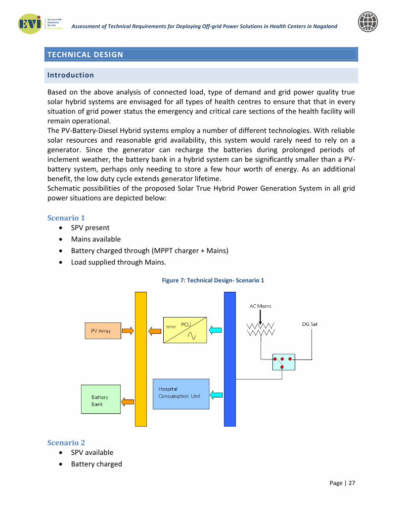
Based on the above analysis of connected load, type of demand and grid power quality true solar hybrid systems are envisaged for all types of health centres to ensure that that in every situation of grid power status the emergency and critical care sections of the health facility will remain operational. The PV-Battery-Diesel Hybrid systems employ a number of different technologies. With reliable solar resources and reasonable grid availability, this system would rarely need to rely on a generator. Since the generator can recharge the batteries during prolonged periods of inclement weather, the battery bank in a hybrid system can be significantly smaller than a PV-battery system, perhaps only needing to store a few hour worth of energy. As an additional benefit, the low duty cycle extends generator lifetime. Schematic possibilities of the proposed Solar True Hybrid Power Generation System in all grid power situations are depicted below:
Scenario 1 SPV present
Mains available
Battery charged through (MPPT charger + Mains)
Load supplied through Mains.
Figure 7: Technical Design- Scenario 1
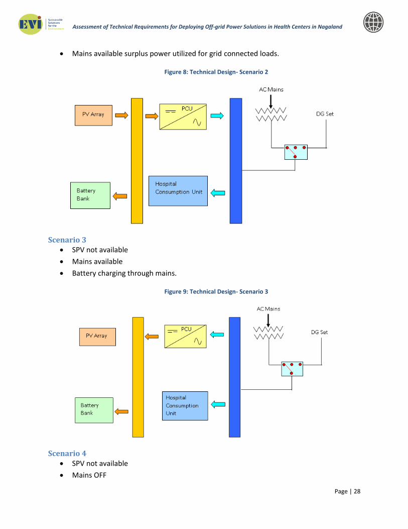
Scenario 2 SPV available
Battery charged
Page | 28
Assessment of Technical Requirements for Deploying Off-grid Power Solutions in Health Centers in Nagaland
Mains available surplus power utilized for grid connected loads.
Figure 8: Technical Design- Scenario 2
Scenario 3 SPV not available
Mains available
Battery charging through mains.
Figure 9: Technical Design- Scenario 3
Scenario 4 SPV not available
Mains OFF

Page | 29
Assessment of Technical Requirements for Deploying Off-grid Power Solutions in Health Centers in Nagaland
Inverter supplying power to grid connected loads through Battery
Figure 10: Technical Design- Scenario 4
Scenario 5 SPV & Mains not available Battery discharged
Start DG command
Battery charging through DG, & Load through DG
Figure 11: Technical Design- Scenario 5
Basis the above configurations for power backup, in various situations, following eight types of Solar Power Generation systems are designed for erection and commissioning in any type of health centre in Nagaland.

Page | 30
Assessment of Technical Requirements for Deploying Off-grid Power Solutions in Health Centers in Nagaland
Table 9: Proposed Solar Power Generation System
Parameters District Health
Centres CHC PHC Sub Centres
T-1 T-2 T-1 T-2 T-1 T-2 T-1 T-2
Connected load (kW) 62.25 46.40 17.00 11.00 6.00 4.00 2.0 1.0
Estimated energy demand (in kWh) 280 213 85 57 33 25 14 5.0
Meteorological and Solar Data
PV Syst simulation analysis was carried out for each of eight system possibilities considering the following mean of available solar data for Nagaland:
Table 10: Daily Solar Insolation
Station Jan Feb Mar Apr May Jun Jul Aug Sep Oct Nov Dec Annual
Mean of Nagaland6 kWh/m
2/day
Month wise Averaged daily Insolation Incident On A Horizontal Surface
4.1 4.61 5.1 5.09 4.9 4.6 4.3 4.3 4.01 4.3 4.4 4.05 4.47
Month wise Averaged daily Clear Sky Insolation Incident On A Horizontal Surface
4.8 5.75 6.9 7.79 8.2 8 7.5 7.3 6.34 5.8 5 4.53 6.49
Month wise Averaged daily Insolation Incident at OPT 5.8 5.74 5.5 5.06 4.9 4.6 4.3 4.3 4.08 5 5.9 6.14 5.1
Month wise Averaged daily Mean 4.52
Monthly Averaged Clear Sky Days 10 6 4 2 1 0 0 0 1 6 11 15
Monthly Averaged Daylight Hours 11 11.3 12 12.7 13 14 14 13 12.3 12 11 10.5 12.1
Table 11: Monthly and Averaged Annual Solar Insolation
Station Jan Feb Mar Apr May Jun Jul Aug Sep Oct Nov Dec Annual
Mean of Nagaland7 kWh/m
2
Monthly Averaged Insolation Incident On A Horizontal Surface
128 129 158 153 152 138 133 133 120 133 131 126 1633.44
Monthly Averaged Clear Sky Insolation Incident On A Horizontal Surface
150 161 214 234 254 240 231 225 190 179 150 140 2368.64
At OPT 180 161 170 152 151 137 133 133 122 153 177 190 1860.37
Mean 150 161 170 153 152 138 133 133 122 153 150 140 1756.12
Average yearly Global Solar Radiant Exposure Average of values above from S.No. 1 to 4 1904.64
Median yearly Global Solar Radiant Exposure - Median of values at S.No. 1 & 4 1808.25
Mean of lowest and average values Mean of values S.No. 5 & 6 1856.44
Value considered for energy generation 97% of value at S.No.-7 1800.00
6 Latitude: 26.3187, Longitude-94.5208, Elevation-1217 7 Latitude: 26.3187, Longitude-94.5208, Elevation-1217
Page | 31
Assessment of Technical Requirements for Deploying Off-grid Power Solutions in Health Centers in Nagaland
Indicative Technical Parameters
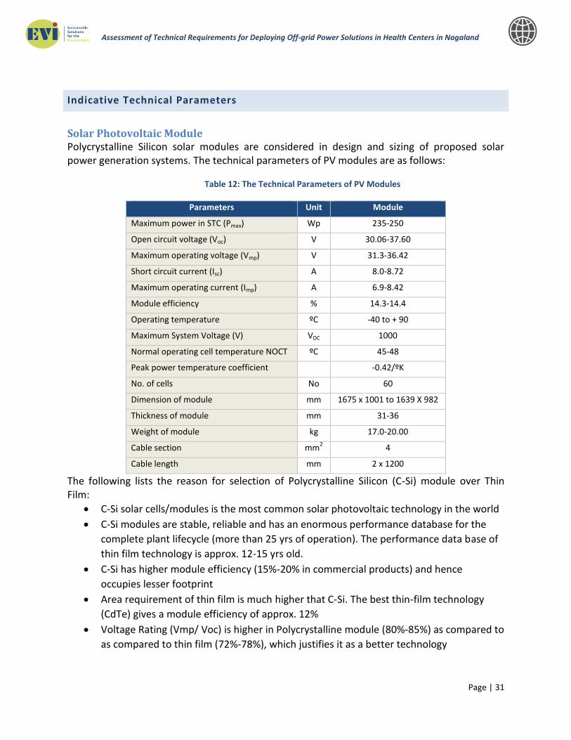
Solar Photovoltaic Module Polycrystalline Silicon solar modules are considered in design and sizing of proposed solar power generation systems. The technical parameters of PV modules are as follows:
Table 12: The Technical Parameters of PV Modules
Parameters Unit Module
Maximum power in STC (Pmax) Wp 235-250
Open circuit voltage (Voc) V 30.06-37.60
Maximum operating voltage (Vmp) V 31.3-36.42
Short circuit current (Isc) A 8.0-8.72
Maximum operating current (Imp) A 6.9-8.42
Module efficiency % 14.3-14.4
Operating temperature ºC -40 to + 90
Maximum System Voltage (V) VDC 1000
Normal operating cell temperature NOCT ºC 45-48
Peak power temperature coefficient -0.42/ºK
No. of cells No 60
Dimension of module mm 1675 x 1001 to 1639 X 982
Thickness of module mm 31-36
Weight of module kg 17.0-20.00
Cable section mm2 4
Cable length mm 2 x 1200
The following lists the reason for selection of Polycrystalline Silicon (C-Si) module over Thin Film:
C-Si solar cells/modules is the most common solar photovoltaic technology in the world
C-Si modules are stable, reliable and has an enormous performance database for the
complete plant lifecycle (more than 25 yrs of operation). The performance data base of
thin film technology is approx. 12-15 yrs old.
C-Si has higher module efficiency (15%-20% in commercial products) and hence
occupies lesser footprint
Area requirement of thin film is much higher that C-Si. The best thin-film technology
(CdTe) gives a module efficiency of approx. 12%
Voltage Rating (Vmp/ Voc) is higher in Polycrystalline module (80%-85%) as compared to
as compared to thin film (72%-78%), which justifies it as a better technology

Page | 32
Assessment of Technical Requirements for Deploying Off-grid Power Solutions in Health Centers in Nagaland
Although C-Si modules has a higher temperature co-efficient, this has higher impact only
in high temperature zones. Nagaland’s ambient temperature is low, hence this effect is
minimized
C-Si modules are robust and easy to handle, whereas thin film modules are fragile and
easily breakable. Polycrystalline module comes with Anodized Aluminium frame, but
thin film is frameless, sandwiched between glasses. Installation of this film module
requires higher level of expertise
Thin film module requires special clips and structures.
Thin film module require more number of circuit combiners and fuses.
Most importantly, there are several C-Si module manufacturers in India and the same is
preferred by MNRE, while thin film hardly has a domestic content in India.
Hence, other than being more expensive, C-Si technology is certainly a better choice for
the project under discussion.
Module Mounting Structure Mounting frames and legs are considered of structural steel angles conforming to IS 2062/ ASTM A36 (Steel for general structural purposes) minimum size-50 x 50 x 6 mm and properly Hot-Dip zinc coated/ galvanized as per IS 4759/ASTM A 123; having fasteners of stainless steel – SS 304. In case of ground mounted system, the base columns are of RCC construction. For rooftop installation, the mounting arrangement is designed as per site specification. For ground mounted systems, the mounting arrangement will have provision for tilting in to three angular position viz. latitude angle, -15º latitude angle and + 15º latitude angle position. For the project, fixed tilt structures are recommended for the following reasons:
Simple and standard design
Easy to fabricate and same can be done through localized sourcing.
Relatively lower cost
No additional operation required and easily maintainable
Orientation is easier
Easier to install in rooftops
DC Side Equipment Array junction/combiner box: Junction boxes considered are conforming to IP 54 protection class II. Every box will be consisting of DC side disconnect switch, fuses and a Type II surge protection device.
Power Conditioning Unit Including Inverters The PCUs/Inverters considered are of high-efficiency, microprocessor-controlled and capable of running in isolated mode. The equipment shall be housed in a suitable weatherproof and insect proof sheet metal cabinet in conformity with IP-54 for degree of ingress protection. All cable

Page | 33
Assessment of Technical Requirements for Deploying Off-grid Power Solutions in Health Centers in Nagaland
termination shall have suitable marker ferrules for easy identification. All doors and covers shall be fitted with suitable gaskets or otherwise designed to limit the entry of dust, vermin & moisture. The doors shall be fitted with suitable locking arrangement. The following types of PCUs are considered for systems to be installed at Sub Centres and Primary Health Centres
Table 13: Type of PCUs Considered for Systems to be Installed at Sub Centres and Primary Health Centres
PCU/Inverter Capacity 2 KVA 3 KVA 6 KVA 8 KVA
System connected load in KW 1 2 4 6
MPPT Charge Controller
Technology MPPT Charge Controller
MPPT Max Voltage (VDC) 90 90 288 360
MPPT Output Voltage 48 48 144 180
MPPT Max Current (Amp) 40 60 40 40
MPPT Efficiency > 93%
Inverter
Technology True Sine Wave Inverter True Sine Wave Inverter
Output Voltage & Regulation 1 Phase, 230 VAC, +/- 2%
Output Frequency 50 Hz +/- 0.5 HZ
Voltage THD < 3%
Inverter Efficiency > 85% > 87% > 88% > 90%
Operating Temperature (up to 50° with deration)
Relative Humidity 95% non-condensing
Protections 1. Short Circuit, 2. Overload Protection, 3. Under Voltage & Over
Voltage of Batteries, 4. Reverse Polarity Protection both for PV and Battery, 5. Output Under & Over Voltage, 6. Surge Protection
Acoustic Noise < 50 DB at 1M
Cooling Forced Air Cooled
Crest Factor 3:1
LED Indication 1. Mains ON 2. Inverter On 3. Battery Low 4. Overload 5. PV On
LCD Display 1. Output Voltage 2. Output Current 3. Output Frequency 4. PV
Voltage 5. PV Current 6. Load Capacity % 7. Battery Voltage
Overload 110% for 5min, 150% for 1 Min
Sleep Mode (Optional) When output load is < 2%
Grid Charger
AC Input 230 VAC +20% -30% , 1
Frequency 50 Hz +/-10%
Charging Current 10 Amps 10 Amps (Higher grid charger available on request)

Page | 34
Assessment of Technical Requirements for Deploying Off-grid Power Solutions in Health Centers in Nagaland
PCU/Inverter Capacity 2 KVA 3 KVA 6 KVA 8 KVA
Charging Type CVCC /
Bidirectional CVCC / Grid Charger
Overload 110% for 1 min, 150% for 5 sec
110% for 5min,150% for 30 sec, 200% for 5 sec
Following types of PCUs are considered for systems to be installed at Community Health Centres and District Health Centres:
Table 14: Type of PCUs Considered for Systems to be Installed at Community Health Centres and District Health Centres
Inverter Capacity 15 KVA 20 KVA 50 KVA 80 KVA
MPPT Charge Controller
MPPT Max Voltage 400 VDC
MPPT Output Voltage 240 V
MPPT Max Current 30A*2Nos 40A*2Nos 40A*5Nos 40A*8Nos
MPPT Efficiency > 93%
Inverter
Output Voltage & Regulation 3 Phase, 4 Wire 415 VAC, +/- 1% for balanced load
Output Frequency 50 Hz +/- 0.5 HZ
Voltage THD < 3%
Inverter Efficiency > 93 % @ 0.8PF
Efficiency Measurement As per IEC 61683
Environmental Testing As per IEC 60068-2 (1, 2, 14, 30)
Operating Temperature 0 to +40°C (up to 50° with deration)
Relative Humidity 95% non-condensing
Protections 1. Output Short Circuit 2. Overload protection 3. Output Under Voltage
4. Output Over Voltage 5. Over Charge Batteries 6. DC Over Voltage
Acoustic Noise < 50 DB at 1M
Cooling Forced Air Cooled
Crest Factor 3:1
LCD Display 1. Output Phase Voltage 2. Output Phase Current 3. Battery Voltage 4. Battery Current 5. Output Frequency 6. Faults 7. Status Information.
Overload 110% for 5min, 150% for 1 Min
Grid Charger
AC Input 415 VAC -20/+15%
Frequency 50 Hz +/-10%
Charging Type CV/CC Charger
Charging Voltage 270V
Page | 35
Assessment of Technical Requirements for Deploying Off-grid Power Solutions in Health Centers in Nagaland
Inverter Capacity 15 KVA 20 KVA 50 KVA 80 KVA
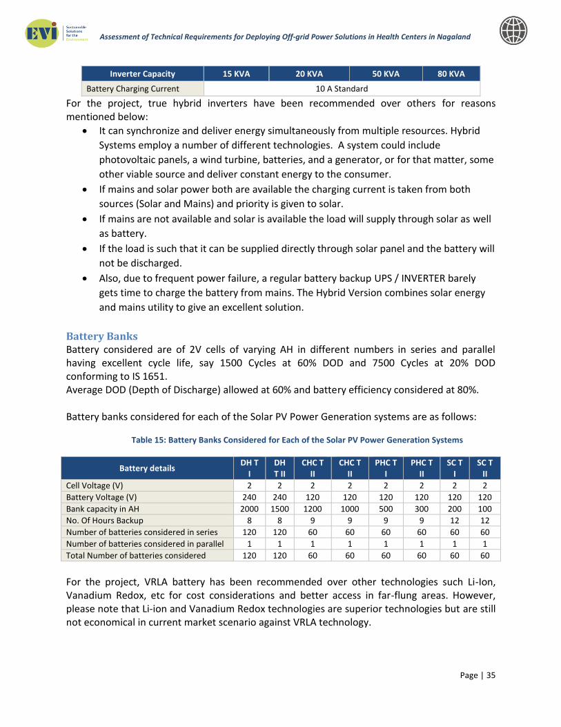
Battery Charging Current 10 A Standard
For the project, true hybrid inverters have been recommended over others for reasons mentioned below:
It can synchronize and deliver energy simultaneously from multiple resources. Hybrid
Systems employ a number of different technologies. A system could include
photovoltaic panels, a wind turbine, batteries, and a generator, or for that matter, some
other viable source and deliver constant energy to the consumer.
If mains and solar power both are available the charging current is taken from both
sources (Solar and Mains) and priority is given to solar.
If mains are not available and solar is available the load will supply through solar as well
as battery.
If the load is such that it can be supplied directly through solar panel and the battery will
not be discharged.
Also, due to frequent power failure, a regular battery backup UPS / INVERTER barely
gets time to charge the battery from mains. The Hybrid Version combines solar energy
and mains utility to give an excellent solution.
Battery Banks Battery considered are of 2V cells of varying AH in different numbers in series and parallel having excellent cycle life, say 1500 Cycles at 60% DOD and 7500 Cycles at 20% DOD conforming to IS 1651. Average DOD (Depth of Discharge) allowed at 60% and battery efficiency considered at 80%. Battery banks considered for each of the Solar PV Power Generation systems are as follows:
Table 15: Battery Banks Considered for Each of the Solar PV Power Generation Systems
Battery details DH T
I DH T II
CHC T II
CHC T II
PHC T I
PHC T II
SC T I
SC T II
Cell Voltage (V) 2 2 2 2 2 2 2 2
Battery Voltage (V) 240 240 120 120 120 120 120 120
Bank capacity in AH 2000 1500 1200 1000 500 300 200 100
No. Of Hours Backup 8 8 9 9 9 9 12 12
Number of batteries considered in series 120 120 60 60 60 60 60 60
Number of batteries considered in parallel 1 1 1 1 1 1 1 1
Total Number of batteries considered 120 120 60 60 60 60 60 60
For the project, VRLA battery has been recommended over other technologies such Li-Ion, Vanadium Redox, etc for cost considerations and better access in far-flung areas. However, please note that Li-ion and Vanadium Redox technologies are superior technologies but are still not economical in current market scenario against VRLA technology.

Page | 36
Assessment of Technical Requirements for Deploying Off-grid Power Solutions in Health Centers in Nagaland
Indicative Parameters of Equipments
Sr. No.
Particulars Reason to select these makes
1 Solar Photovoltaic modules
1.) Annual degradation 0.7 %.
2.) 7 % degradation in 10 years
3.) Linear degradation warranty
4.) Positive PMPP tolerance range is 0 ~ + 3% offered.
2 Power Conditioning Unit / Inverter
1.) MPPT above 3KW or above system installation; else,
PWM for systems below 3KW. Please note that MPPT is
minimally available for systems of low capacity. All
equipments should be IC certified – IP65 with a web
connectivity and good local after sales service
3 Interconnection Cables
1.) Tin plated copper for interconnection between modules and
module to junction box size; cable size of 4 sq.mm
2.) Solar grade cables; Reputed makes,
4 AC cables
1.) Reputed make optimized rated capacity,
2.) Only Copper Cables
3.) Compatible to system requirement
5 Array Junction Boxes
1.) Should be minimum IP-65 grade with minimum 5 in - 1 out
configuration.
2.) Equipped with reverse protection diodes and with SPD surge
protection device level 2;
3.) MoV is not allowed
4.) Should have MC 4 connector as terminal block
6 External Circuit Interconnection Box
MC4 - IP65 with optimized current and voltage rating compatible with external circuit and solar system
Performance (Efficiency) Matrix
The performance of proposed solar power generation systems/plants will be the Capacity Utilization Factor (CUF), which is the ratio of the actual electricity output from the system, to the maximum possible output during the year. The estimated output from the proposed solar power systems/plants are calculated, using standard PV Syst software. But since there are several variables which contribute to the final output from a plant, the CUF varies over a wide range. These could be on account of poor selection /quality of panels, derating of modules at

Page | 37
Assessment of Technical Requirements for Deploying Off-grid Power Solutions in Health Centers in Nagaland
higher temperatures, other design parameters like ohmic loss, atmospheric factors such as prolonged cloud cover and mist.
Therefore performance of the proposed PV power systems/plants however will depend on following several parameters:
Site location, solar insolation levels, climatic conditions specially temperature, technical losses in cabling, module mismatch, soiling losses, MPPT losses, transformer losses and the inverter losses.
There could also be losses due to module degradation through aging. Some of these are specified by the manufacturer, such as the dependence of power output on temperature, known as temperature coefficient.
Of all above mentioned parameters following factors are considered as key performance indicators:
1. Radiation at the site
2. Losses in PV systems
3. Temperature and climatic conditions
4. Design parameters of the plant
5. Inverter efficiency
6. Module Degradation due to aging
7. Operation and Maintenance practices (such as module cleaning)
8. Plant uptime
Losses in PV Solar systems The estimated system losses are all the losses in the system, which cause the power actually
delivered to the AC side of the inverter lower than the power produced by the PV modules. All the causes for this loss, such as losses in cables, power inverters, dirt (dew) on the modules, ambient temperature, varying insolation levels and so on are considered while designing the PV systems.
Reflection Losses PV module power ratings are determined at standard test conditions, which require
perpendicular incident light. Under field conditions larger incidence angles occur, resulting in higher reflection losses than accounted for in the nominal power rating. Calculations show that for modules faced towards the equator, and with a tilt angle equal to the latitude, yearly reflection losses relative to STC are about 1.
Soiling Soiling of solar panels can occur as a result of dust and dirt accumulation. In most cases, the
material is washed off the panel surface by rainfall; however dirt like bird droppings may stay even after heavy rains. The most critical part of a module is the lower edge. Especially with rather low inclinations, soiling at the edge of the frame occurs. By often repeated water collection in the shallow puddle between frame and glass and consecutive evaporation dirt
Page | 38
Assessment of Technical Requirements for Deploying Off-grid Power Solutions in Health Centers in Nagaland
accumulates. Once it causes shading of the cells, this dirt reduces the available power from a module. The losses are generally 1; however the power is restored if the modules are cleaned.
Mismatch Effects Mismatch losses are caused by the interconnection of solar modules in series and parallel. The
modules which do not have identical properties or which experience different conditions from one another. Mismatch losses are a serious problem in PV modules and arrays because the output of the entire PV array under worst case conditions is determined by the solar module with the lowest output. Therefore the selection of modules becomes quite important in overall performance of the plant.
Maximum Power Point Tracking (MPPT) Losses Power output of a Solar PV module changes with change in direction of sun, changes in solar
insolation level and with varying temperature. The power vs. voltage curve of the module there is a single maximum of power. There exists a peak power corresponding to a particular voltage and current. It is desirable to operate the module at the peak power point so that the maximum power can be delivered to the load under varying temperature and insolation conditions. Hence maximization of power improves the utilization of the solar PV module. A maximum power point tracker (MPPT) is used for extracting the maximum power from the solar PV module and transferring that power to the load. A DC/DC converter (step up/step down) serves the purpose of transferring maximum power from the solar PV module to the load. Maximum power point tracking is used to ensure that the panel output is always achieved at the maximum power point. Using MPPT significantly increases the output from the solar power plant.
Inverter Efficiency A solar PV inverter is a type of electrical inverter that is made to change the direct current
(DC) electricity from a photovoltaic array into alternating current (AC) for feeding into the utility grid. These inverters may be stand alone inverters, which are used in isolated systems, or grid tie inverters which are used to connect the power plant to the grid. The efficiency of an inverter has to do with how well it converts the DC voltage into AC. The currently available grid connected inverters have efficiencies of 93 to 98.5, and hence choosing the correct inverter is crucial to the design process.
Solar Plant Design The critical factors which are considered for design include proper selection of modules,
optimum angle of tilt, minimization of Ohmic losses with proper selection of conductors, selection of efficient transformers and inverters etc. Therefore, use of reliable and long life components for the proposed high capital intensive solar power systems/plants.
The actual energy output from the PV system will ultimately depend on the following factors:
• The PV efficiency decreasing with increasing temperature.
• Module show decreasing efficiency with low light intensity.
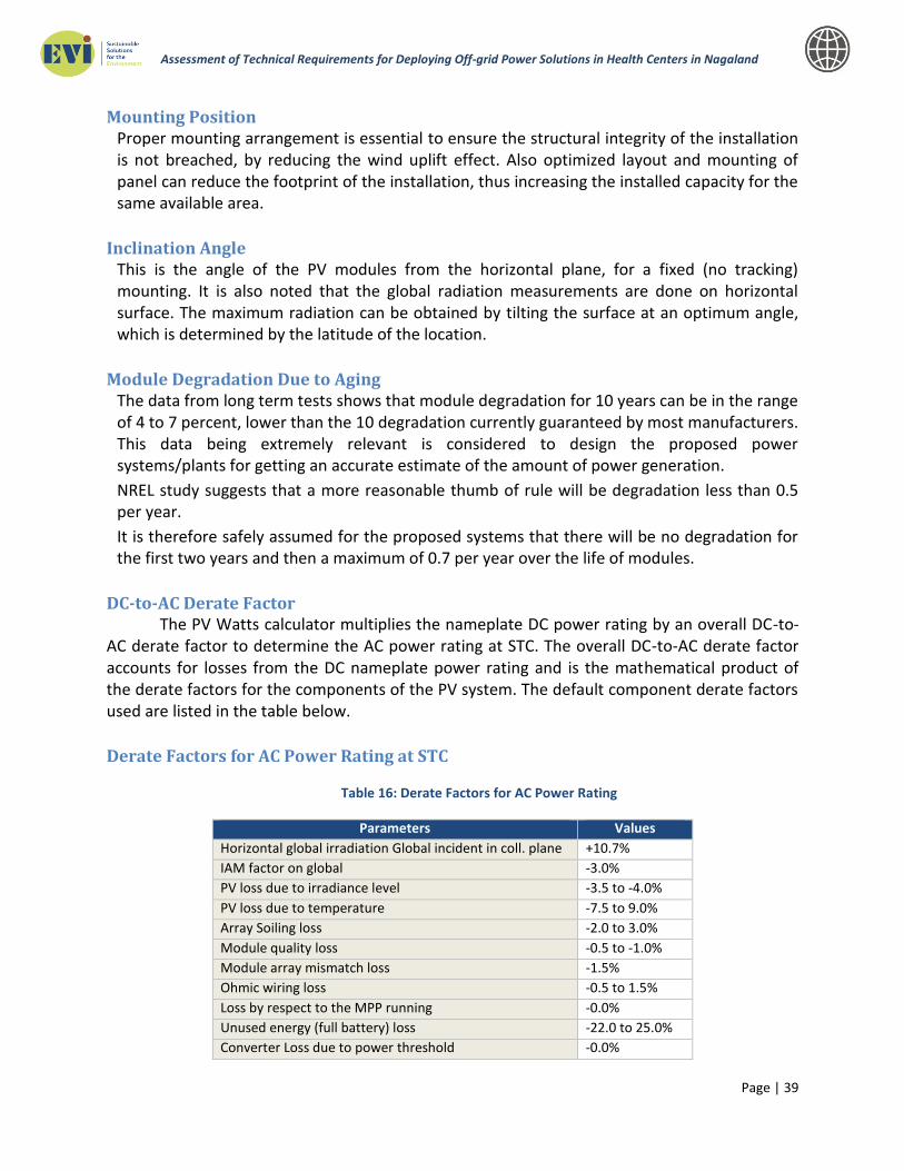
Page | 39
Assessment of Technical Requirements for Deploying Off-grid Power Solutions in Health Centers in Nagaland
Mounting Position Proper mounting arrangement is essential to ensure the structural integrity of the installation
is not breached, by reducing the wind uplift effect. Also optimized layout and mounting of panel can reduce the footprint of the installation, thus increasing the installed capacity for the same available area.
Inclination Angle This is the angle of the PV modules from the horizontal plane, for a fixed (no tracking)
mounting. It is also noted that the global radiation measurements are done on horizontal surface. The maximum radiation can be obtained by tilting the surface at an optimum angle, which is determined by the latitude of the location.
Module Degradation Due to Aging The data from long term tests shows that module degradation for 10 years can be in the range
of 4 to 7 percent, lower than the 10 degradation currently guaranteed by most manufacturers. This data being extremely relevant is considered to design the proposed power systems/plants for getting an accurate estimate of the amount of power generation.
NREL study suggests that a more reasonable thumb of rule will be degradation less than 0.5 per year.
It is therefore safely assumed for the proposed systems that there will be no degradation for the first two years and then a maximum of 0.7 per year over the life of modules.
DC-to-AC Derate Factor The PV Watts calculator multiplies the nameplate DC power rating by an overall DC-to-AC derate factor to determine the AC power rating at STC. The overall DC-to-AC derate factor accounts for losses from the DC nameplate power rating and is the mathematical product of the derate factors for the components of the PV system. The default component derate factors used are listed in the table below.
Derate Factors for AC Power Rating at STC
Table 16: Derate Factors for AC Power Rating
Parameters Values
Horizontal global irradiation Global incident in coll. plane +10.7%
IAM factor on global -3.0%
PV loss due to irradiance level -3.5 to -4.0%
PV loss due to temperature -7.5 to 9.0%
Array Soiling loss -2.0 to 3.0%
Module quality loss -0.5 to -1.0%
Module array mismatch loss -1.5%
Ohmic wiring loss -0.5 to 1.5%
Loss by respect to the MPP running -0.0%
Unused energy (full battery) loss -22.0 to 25.0%
Converter Loss due to power threshold -0.0%

Page | 40
Assessment of Technical Requirements for Deploying Off-grid Power Solutions in Health Centers in Nagaland
Parameters Values
Converter Loss during operation (efficiency) -8.0%
Converter Loss due to voltage threshold 0.0%
Converter Loss over nominal conv. voltage -0.2 to -0.5%
Battery Stored Energy balance +0.2 to +0.5%
Battery efficiency loss -5.0 to 7.0%
Gassing Current (electrolyte dissociation) -1.5%
Battery Self-discharge Current -0.2%
Missing Energy 1.0 to 5.0%
Overall loss -42.0 to -50.0%
System Design
Table 17: Final System Designed Size and Configuration
Parameters District Health
Centres CHC PHC Sub Centres
T-1 T-2 T-1 T-2 T-1 T-2 T-1 T-2
Connected load (kW) 62.25 46.40 17.00 11.00 6.00 4.00 2.0 1.0
Estimated energy demand (in kWh) 280 213 85 57 33 25 14 5.0
Solar Power generation System designed size
Solar PV module and array details
Module Maximum power in STC (Vmax) 250 250 250 250 250 250 250 250
Proposed Installed Solar PV capacity (kWp) 65 48 20 15 7.5 5.0 3.0 1.5
Module in series (Nos) 13 12 8 6 5 4 4 2
Module in Parallel (Nos) 20 16 10 10 6 5 3 3
Total modules 260 192 80 60 30 20 12 6
PV array Voltage (VDC) 390 360 240 180 150 120 120 60
PV array (Amp) 160 128 80 80 48 40 24 24
Energy to charge controller (kWh) 277 188 79 58 30 20 12 6.5
Power conditioning Unit
MPPT input Max voltage (V) 400 400 400 400 360 288 90 90
MPPT output Max voltage (V) 240 240 240 240 180 144 48 48
Max charging current (A) 320 200 80 60 40 40 60 40
Inverter capacity (KW/kVA) 75/80 50 20 15 6 4 3 1
Inverter Output Voltage (V AC) 440 V, AC, 3 Ph, 4 wire,
50 Hz 230 V, AC, 1 Ph, 2 wire, 50 Hz
Battery details
Cell Voltage (V) 2 2 2 2 2 2 2 2
Battery Voltage (V) 240 240 120 120 120 120 120 120
Bank capacity in AH 2000 1500 1200 1000 500 300 200 100
Number of batteries considered in series 120 120 60 60 60 60 60 60
Number of batteries considered in parallel 1 1 1 1 1 1 1 1
Total Number of batteries considered 120 120 60 60 60 60 60 60
Total Energy to be stored (kWh) 480 360 144 120 60 36 24 12
Energy can be drawn (60% DOD)-kWh 288 216 86.4 72 36 21.6 14.4 7.2
Energy can be converted after losses (kWh) 230.4 172.8 69.1 57 28.8 17.2 11.5 5.8
Ultimate energy available at AC side Load DBs (kWh)
214.3 160.7 64.2 53 26.7 16 10.7 5

Page | 41
Assessment of Technical Requirements for Deploying Off-grid Power Solutions in Health Centers in Nagaland
SLDs of the Designed Proposed Solar Power Generation Systems for Nagaland Health Centres
System Type-1 for District Health Centres
Figure 12: Technical Design for DHC System Type-1
DG SET
65 kWp PV module Energy from PV
274.95 kWh
PCU-75 kW, 440 V AC,
Charge Controller-324.22 A
Charging by charge controller
2 V cell, 2000 AH 120 Nos in series battery bank Out put V-240 V DC
Base load 8.50 kW
72.00 kWh
Critical load-1 14.25 kW 64.5 kWh
Critical load-2 15.95 kW
64.45 kWh
Total Emergency load
62.25 kW 214.3 kWh
Critical load-3 23.55 kW
79.05 kWh

Page | 42
Assessment of Technical Requirements for Deploying Off-grid Power Solutions in Health Centers in Nagaland
System Type-2 for District Health Centre
Figure 13: Technical Design for DHC System Type-2

Page | 43
Assessment of Technical Requirements for Deploying Off-grid Power Solutions in Health Centers in Nagaland
System Type-1 for Community Health Centre
Figure 14: Technical Design for CHC System Type-1
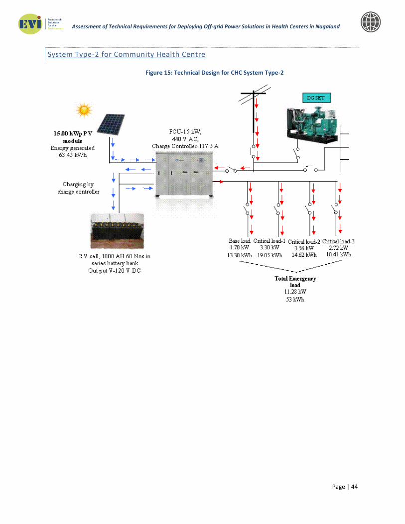
Page | 44
Assessment of Technical Requirements for Deploying Off-grid Power Solutions in Health Centers in Nagaland
System Type-2 for Community Health Centre
Figure 15: Technical Design for CHC System Type-2

Page | 45
Assessment of Technical Requirements for Deploying Off-grid Power Solutions in Health Centers in Nagaland
System Type-I for Primary Health Centre
Figure 16: Technical Design for PHC System Type-1

Page | 46
Assessment of Technical Requirements for Deploying Off-grid Power Solutions in Health Centers in Nagaland
System Type-2 for Primary Health Centre
Figure 17: Technical Design for PHC System Type-2

Page | 47
Assessment of Technical Requirements for Deploying Off-grid Power Solutions in Health Centers in Nagaland
System Type-I for Sub Primary Health Centre
Figure 18: Technical Design for Sub Centre System Type-1
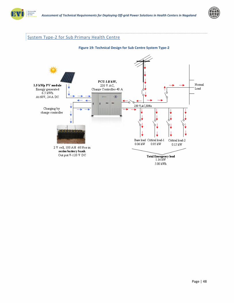
Page | 48
Assessment of Technical Requirements for Deploying Off-grid Power Solutions in Health Centers in Nagaland
System Type-2 for Sub Primary Health Centre
Figure 19: Technical Design for Sub Centre System Type-2

Page | 49
Assessment of Technical Requirements for Deploying Off-grid Power Solutions in Health Centers in Nagaland
CAPITAL COST ESTIMATION
The capital cost for the proposed solar PV power generation system in each category of health centres has been estimated. Refer to the table for the cost estimations:
Based on afore indicated final system design and configuration- a budgetary capital cost estimated has been calculated for each type of solar photovoltaic installation, as mentioned in the tables above. The estimate has been segregated broadly as per standard sub activity. The generic description of components and their technical specifications are already detailed above. The transportation cost for supplied components have been considered till Siliguri only. The Ministry of Commerce and Industry, GoI, provides a transport subsidy for the north eastern region which shall be availed in this case. Prior to commencement of an installation, a detailed survey for the site is to be carried out for understanding the existing electrical circuit and layout of the health centre. Any internal up gradation to the internal electrical network necessary for incorporating the solar hybrid installation is to be evaluated. The price for such up gradation is not included in the above estimate. Furthermore, in case of roof top installation is being considered for a specific centre, the load bearing capability of that particular roof is to be checked and any reinforcement required shall be undertaken as an independent exercise.
O&M Costs
The O&M cost is based on the service type to be undertaken contractually. Currently, there are
4 different kind of services included in the O&M Contract shown below:
O&M contract Type Cost*
Comprehensive On-Site Warranty 10%
Comprehensive Off-Site Warranty 8%
Warranty on Demand excluding spares 6%
Online Support/Call Support 2%
*Cost is on percentage basis of the total capital cost for the project
Based on the above, it is recommended that O&M services be undertaken through Online
Support/Call Support for the project which is estimated at 2% of the project cost.
This is due to the fact (as indicated in the O&M section of the report) that general scheduled
maintenance of solar system is a simple process and hence it is recommended that local health
centre undertake O&M on a daily basis at the health center. Further, entrepreneurs in central

Page | 50
Assessment of Technical Requirements for Deploying Off-grid Power Solutions in Health Centers in Nagaland
areas of districts be trained to provide services for specific unscheduled
maintenance/breakdowns on need basis. Therefore, the overall cost in due course can be
reduced to 0%, wherein, the local entrepreneurs will be able to provide local support for any
breakdown. However, please note that spares will need to be allotted accordingly for such
support. It is general practice to have basic spares included in the EPC contract as indicated in
the RFQ.
For the recurring capital costs, the batteries will require replacement every 5 years on an
average and hence, additional cost of battery storage (as shown in above table) will be incurred
every 5 years throughout the lifecycle (25 years) of the project.
Table 18: Recurring O&M Cost Estimation for the Proposed Solar PV Power Generation Systems in District Health Centre and Community Centre
Recurring Cost for O&M Year 5 Year 10 Year 15 Year 20
Solar PV Module 250 Wp 2% of Total Panel Cost
Misc Spares (such as Fuse, Relays, Terminal Blocks, Connectors of PCU, Distilled water for Battery, Terminals, Cable, Cable Connectors, Anti Theft Screws along with saw)
0.25% of Total Cost
Battery Bank in AH, 2V, 2000AH in No’s Complete
Substitution Complete
Substitution Complete
Substitution Complete
Substitution
O&M Contract 2% of CAPEX
per year 2% of CAPEX
per year 2% of CAPEX
per year 2% of CAPEX
per year
OPERATION AND MAINTENANCE OF SOLAR POWER SYSTEM
PV systems have been the focus of numerous efforts for rural electrification. The panels themselves typically have a very long lifetime (20-30 years). Unfortunately, installation programs do not always include a sufficient service component. Many health centers describe experiences with PV systems with inoperative batteries, resulting in, for example, lights and fans only operate when the sun is shining. Regular maintenance on batteries is essential; they should be checked every month, with the electrolyte level replenished as needed. Properly maintained, batteries should last several years before needing replacement. While training local health centre staff in system maintenance is essential for routine maintenance, a professional technician should also perform an annual maintenance check, examining wiring connections, mounting bolts, and inverter operation. Operation & Maintenance of the solar plant is consists of the following

Page | 51
Assessment of Technical Requirements for Deploying Off-grid Power Solutions in Health Centers in Nagaland
a. Routine operation & maintenance of the solar PV power plant including its associated array, inverters, power control units, and all civil structures, control room buildings, Battery etc. on day to day (24x7) basis b. Scheduled and unscheduled maintenance of the facility, c. Civil maintenance d. Security of the facility e. Data collection and analysis
Scheduled Maintenance Scheduled maintenance ideally includes regular cleaning of modules, checking connections and combiner box, inverter servicing, checking structures etc. It is required to scheduled maintenance as scheduled below
Table 19: Maintenance Schedule
Cleaning of Solar PV Modules Every 15 Days
Tightening of Electrical Connections Every 1 Month
Inverter Servicing Every 6 Months
Checking of Structure and Civil Every 6 Months
Checking of Battery Every 1 Month
Unscheduled Maintenance Unscheduled maintenance is carried out in response to failures. As such, the key parameter when considering unscheduled maintenance is diagnosis, speed of response and repair time. Although the shortest possible response is preferable for increasing energy yield, this should be balanced against the likely increased contractual costs of shorter response times. The agreed response times should be clearly stated within the O&M contract and will depend on the site location— and whether it is manned. Depending on the type of fault, an indicative response time may be within 48 hours, with liquidated damages if this limit is exceeded. The majority of unscheduled maintenance issues are related to the inverters. This can be attributed to their complex internal electronics, which are under constant operation. Depending on the nature of the fault, it may be possible to rectify the failure remotely – this option is clearly preferable if possible. Other common unscheduled maintenance requirements include:
Tightening cable connections that have loosened.
Replacing blown fuses.
Repairing lightning damage.
Repairing equipment damaged by intruders or during module cleaning.
Repairing mounting structure faults.
Operation and Maintenance Procedure Check the following items before starting operation work.

Page | 52
Assessment of Technical Requirements for Deploying Off-grid Power Solutions in Health Centers in Nagaland
Refer to the inverter manual for more information about inverter maintenance and
electrical work.
Maintenance and Care Under most weather conditions, normal rainfall is sufficient to keep the PV module glass
surface clean. If dust or dirt build-up becomes excessive, clean the glass only with a soft
cloth using mild detergent and water.
Do not clean the modules with cold water during the warmer hours of the day in order
to avoid creating any thermal shock that may damage the module.
Be cautious when cleaning the back surface of the module to avoid penetrating the
substrate material. Modules that are mounted flat (0° tilt angle) should be cleaned more
often, as they will not ''self clean'' as effectively as modules mounted at a 15° tilt or
greater.
At least once a year, it is recommended to check the torque of terminal screws and the
general condition of wiring. Also, check that mounting hardware is properly torque.
Loose connections will result in damage to the array.
Modules that have been replaced must be of the same type. Do not touch live parts of
cables and connectors. Use appropriate safety equipment (insulated tools, insulating
gloves, etc.) when handling modules.
Cover the front surface of modules by an opaque material when repairing. When
exposed to sunlight, modules generate high voltage and thus dangerous. Solar SPV
modules are equipped with bypass diodes in the junction box. This minimizes module
heating and current losses.
Do not try to open the junction box to change the diodes even if it malfunctions. This
should be done by qualified personnel only.
In a system that uses a battery, blocking diodes are typically placed between the battery
and the SPV module output to prevent battery discharge at night.
Condition of Roof where Solar Power System has been Installed It is important to inspect the structural integrity of the roof and the durability of the roof materials. The mounting structure and solar modules require a strong base for durable and reliable operation in local environments. Always wear a safety harness when working on the roof. Inspect the roof surface in the area of the operation for cracks, water leakage, and roof material quality and uniformity. This is especially important if the roof is older than 10 years. Inspect the roof for sags and other abnormalities. A sag or deep depression in the roof may indicate a structural weakness in the support system that may require correction. The following illustrations detail typical roof construction as well as old roof problems.

Page | 53
Assessment of Technical Requirements for Deploying Off-grid Power Solutions in Health Centers in Nagaland
Check that all rafters, trusses and other materials are in good condition.
Check for indication of previous water leaks.
Spare Parts Management In order to facilitate a rapid response, a suitably stocked spares inventory is essential. The numbers of spares required will depend on the size of the plant and site-specific parameters. Adequate supplies of the following components should be held:
Mounting structure pieces.
Junction/combiner boxes.
Fuses
DC and AC cabling components.

Mon District Hosiptal DPR

GAPS ASSESSMENT REPORT
Of
NAGALAND
DISTRICT HOSPITAL

LIST OF ABBREVIATION S
Abbreviations Full Name
CEA Central Electricity Authority
GRID Means High Voltage Backbone System Of Interconnecting
Transmission Lines, Substations And Generating Plants
DPR Detailed Project Report
DEVELOPER Entity Which Develops Project
AFC Annual Fixed Cost
CAPTIVE USER End User Of The Electricity Generated In A Captive Generating Plant
RENEWABLE
ENERGY
Means The Grid Quality Energy/Power Generated From Renewable
Energy Sources
RENEWABLE
ENERGY
SOURCES
Renewable Sources Such As Solar In This Case Including Its
Integration With Combined Cycle, Biomass, Bio Fuel Cogeneration,
Urban/Municipal Waste And Other Such Sources As Approved By The
MNRE
SOLAR PV
POWER
The Solar Photo Voltaic (PV) Power Project That Uses Sunlight For
Direct Conversion Into Electricity Through Photo Voltaic Technology.
SOLAR
THERMAL
POWER
Solar Thermal Power Project That Uses Sunlight For Direct
Conversion Into Electricity Through Concentrated Solar Power
Technology Based On Either Line Focus Or Pointy Focus Principle.
ETC Evacuated Tube Collector
FPC Flat Plate Collector
SPV Solar Photovoltaic
SPP Solar Photovoltaic Pump
AH Ampere Hour
KWH-DAY Kilo Watt Hour Per Day
KWH/M2 Kilo Watt Hour Radiation Per Square Meter Area
KVA Kilo Volt
KV Kilo Volt Ampere
KWH Kilo Watt Hour
MW Mega Watt
WP Watt Peak
LED Light Emitting Diode
APAC Asia-Pacific or Asia Pacific
CHC Community Health Centre
PHC Primary Health Centre

Gaps Assessment for District Hospital MON Draft Final Report
3
Table of Contents
List of Abbreviations ....................................................................................................................................................... ii
1. About the PROJECT ................................................................................................................................................ 4
2. Objectives of the assignment ............................................................................................................................. 7
3. Methodology ............................................................................................................................................................. 8
3.1 Process Flow .......................................................................................................................................................... 8
3.2 Checklist /Key Information Areas ................................................................................................................. 9
4. Findings from Hospital Assessment ............................................................................................................. 12
4.1 Current Status on Infrastructure and Gaps ...................................................................................... 12
4.1.1 Electricity .............................................................................................................................................. 13
5. CONCULSIONS, RECOMMENDATIONS AND COSTING .......................................................................... 26
Annexure I: LIST OF DOCUMENTS REFERRED .................................................................................................. 28
Annexure II: LIST OR PEOPLE MET ........................................................................................................................ 30
Annexure III: TERMS OF REFERENCE ................................................................................................................... 31

Gaps Assessment for District Hospital MON Draft Final Report
4
1. ABOUT THE PROJECT
NAGALAND HEALTH PROGRAM
Non Renewable Energy "A non-renewable resource is a natural resource that cannot be re-made or re-grown at a scale comparable to its consumption”.
Coal Petroleum Natural Gas Limited
Source: Coal, petroleum, and natural gas are considered non-renewable because they cannot be replenished in a short period of time. "Renewable Energy is energy that is derived from natural processes that are replenished constantly. In its various forms, it derives directly or indirectly from the sun.”
The District of Mon, which covers an area of 1786 Sq. km, is bounded on the North by Sibsagar District of
Assam, on the South by Tuensang District of Nagaland and Myanmar (Burma), on the East by Myanmar
(Burma) and on the West by Tuensang and Mokokchung Districts of Nagaland. On the Northeast lies the Tirap
District of Arunachal Pradesh. The altitude of Mon district headquarters is 897.64 meters above sea level.
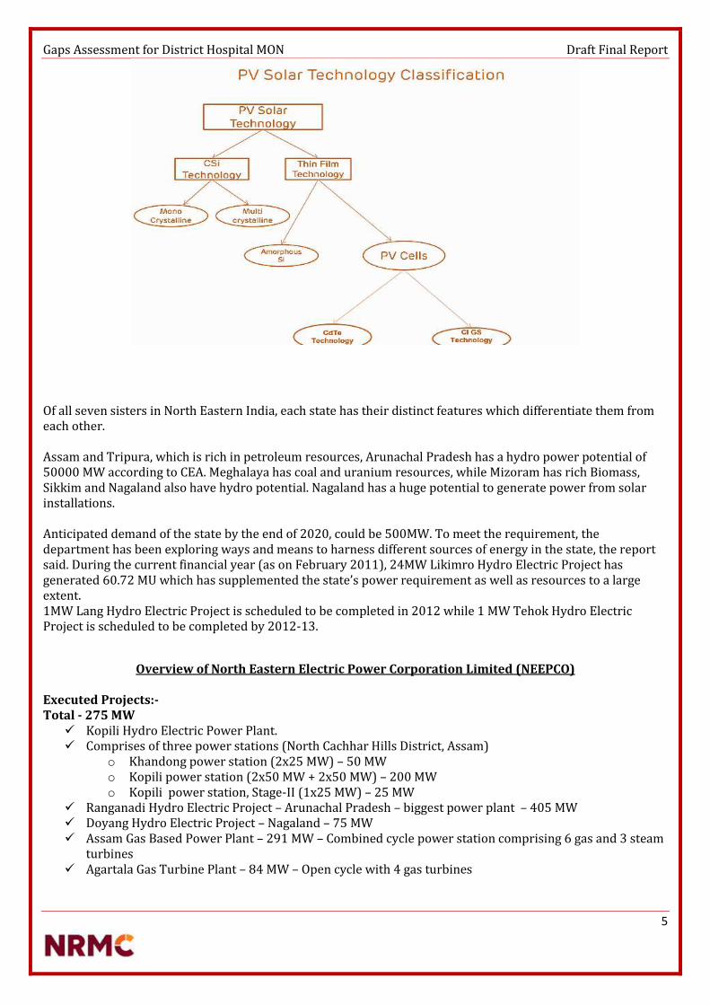
Gaps Assessment for District Hospital MON Draft Final Report
5
Of all seven sisters in North Eastern India, each state has their distinct features which differentiate them from each other.
Assam and Tripura, which is rich in petroleum resources, Arunachal Pradesh has a hydro power potential of 50000 MW according to CEA. Meghalaya has coal and uranium resources, while Mizoram has rich Biomass, Sikkim and Nagaland also have hydro potential. Nagaland has a huge potential to generate power from solar installations.
Anticipated demand of the state by the end of 2020, could be 500MW. To meet the requirement, the department has been exploring ways and means to harness different sources of energy in the state, the report said. During the current financial year (as on February 2011), 24MW Likimro Hydro Electric Project has generated 60.72 MU which has supplemented the state’s power requirement as well as resources to a large extent. 1MW Lang Hydro Electric Project is scheduled to be completed in 2012 while 1 MW Tehok Hydro Electric Project is scheduled to be completed by 2012-13.
Overview of North Eastern Electric Power Corporation Limited (NEEPCO)
Executed Projects:- Total - 275 MW
Kopili Hydro Electric Power Plant. Comprises of three power stations (North Cachhar Hills District, Assam)
o Khandong power station (2x25 MW) – 50 MWo Kopili power station (2x50 MW + 2x50 MW) – 200 MWo Kopili power station, Stage-II (1x25 MW) – 25 MW
Ranganadi Hydro Electric Project – Arunachal Pradesh – biggest power plant – 405 MW Doyang Hydro Electric Project – Nagaland – 75 MW Assam Gas Based Power Plant – 291 MW – Combined cycle power station comprising 6 gas and 3 steam
turbines Agartala Gas Turbine Plant – 84 MW – Open cycle with 4 gas turbines
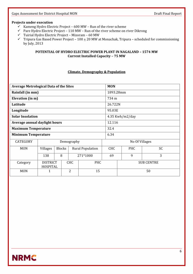
Gaps Assessment for District Hospital MON Draft Final Report
6
Projects under execution Kameng Hydro Electric Project – 600 MW – Run of the river scheme Pare Hydro Electric Project – 110 MW – Run of the river scheme on river Dikrong Tuirial Hydro Electric Project – Mizoram – 60 MW Tripura Gas Based Power Project – 100 + 20 MW at Monachak, Tripura – scheduled for commissioning
by July, 2013
POTENTIAL OF HYDRO ELECTRIC POWER PLANT IN NAGALAND – 1574 MW Current Installed Capacity – 75 MW
Climate, Demography & Population
Average Metrological Data of the Sites MON
Rainfall (in mm) 1893.28mm
Elevation (in m) 734 m
Latitude 26.722N
Longitude 95.03E
Solar Insolation 4.35 Kwh/m2/day
Average annual daylight hours 12.116
Maximum Temperature 32.4
Minimum Temperature 6.34
CATEGORY Demography No Of Villages
MON Villages Blocks Rural Population CHC PHC SC
138 8 271*1000 69 9 3
Category DISTRICT HOSPITAL
CHC PHC SUB CENTRE
MON 1 2 15 50

Gaps Assessment for District Hospital MON Draft Final Report
7
2. OBJECTIVES OF THE AS SIGNMENT
The objective of the study is to support the Nagaland health department, in accessing the needs, defining technical requirements and planning investments to provide appropriate technology for health facilities of different districts.
Strategies for improving working conditions in public hospitals 24 hours power supply in district hospital of MON, Nagaland
To access to a strong utility grid. They have had to rely on engine- or turbine-driven generator sets that, while highly reliable, typically produce power at a much higher cost than a large utility. Now a better model is emerging that combines newly cost-effective renewable energy from wind or solar sources with conventional diesel- or gas-fueled generation. These installations, called hybrid micro grids, also employ energy storage to add power system stability and enable further energy cost reduction. Aided by sharp declines in the cost of wind and solar energy, as well as lower energy storage costs relative to the price of fuel, hybrid micro grids are well suited to a host of applications, including individual buildings, resorts, mine sites, remote villages, small islands and others. Keeping the systems healthy in a district hospital is an essential part for well-being of the entire state. However, it can be challenging to stay up-to-date with the requirements and developments of hospital mechanical and electrical systems. There are many low-cost things we can do from a design standpoint that can reduce energy use. Electrical systems control nearly every aspect of a modern hospital. A hospital’s electrical system must provide reliable, disturbance-free power around the clock. Furthermore, it must be exceedingly safe, because patients are often in vulnerable states. All of this must be accomplished according to overlapping regulations from national and local authorities.
District Health Centre (High energy requirements) (>=50 Beds) Medical equipment similar to Category I Health Centre; frequency of use and number of devices are key
factors of differentiation between Category I and II health centers. Separate refrigerators may be used for food storage and cold chain May accommodate more sophisticated diagnostic medical equipment and perform more complex
surgical procedures.
The technology-driven hybrid power systems are characterized by high initial investments and low
switching cost. The abundant availability of component manufacturers as well as numerous
government incentives has fuelled the demand for and adoption of hybrid power systems across
developing economies. The lack of grid connectivity in remote and rural areas and its sheer unreliability
has boosted the installation of these power systems in recent years.
Hybrid power systems combine renewable energy sources such as wind and solar and energy produced
by conventional means such as diesel generators. By type, hybrid power systems include wind-solar-
diesel hybrid, PV-diesel hybrid, and others such as wind-hydro-diesel hybrid, solar thermal, and hybrid-
solar biomass. It will retain its dominance over other segments. Over the past few years, wind-solar-
diesel hybrid systems for rural electrification have been enormously developed by various stakeholders
across developing countries such as Indonesia, India, China, and South Africa.
The integration of renewable energy production with the electricity mix also reduces the cost of
transporting fuel to remote areas in the region. Japan is the leading contributor in the APAC hybrid
power systems, with the surge in utility-scale and commercial projects expected to drive demand in the
coming years. Over the past few years, the country has witnessed a rapid increase in the number of
companies registering to sell retail power

Gaps Assessment for District Hospital MON Draft Final Report
8
3. METHODOLOGY
3.1 Process Flow
Data collection for the systematic review was done by extracting relevant research studies from the site surveys by various technical experts. Data extraction allowed the researchers to determine which data was most important in answering the problems faced by various staffs at the hospital.
The poor working conditions are attributed to poor infrastructure, inadequate resources, lack of safety and security, poor interpersonal relationships, lack of involvement in decision making and lack of support from governing body. The study revealed that effective management at hospital level may create an enabling working environment modifying the impact of resource shortfalls.
The complete area was surveyed, MS and staffs took us around the entire area, explained few things what they go through because of the poor infrastructure facilities and policies. The area was studied; proper checklist sheet was worked on as per the data available. There were certain parameters which were not available, few things were not even known to the staffs.
Site analysis of the hospital. The feasibility for solar in that area The availability of space for the necessary installation. The availability of grid & other alternate supplies.
Each and every small detail was considered and every site was not only surveyed but also analysed, worked upon, to finally prepare the draft.

Gaps Assessment for District Hospital MON Draft Final Report
9
3.2 Checklist /Key Information Areas
Location (District, State) MON
Latitude 26.722N
Longitude 95.03E
Age of Building New & Old
Roof Type (NEW) Rcc
No. of Floors(NEW) G+3
Height of terrace from ground level 50 feet
Load bearing capacity of terrace (Need to be discussed with civil engineer as location is in seismic zone 5)
No. of Floors(OLD) G+1
Roof Type (OLD) Rcc
Height of terrace from ground level 24 feet
Load bearing capacity of terrace (Need to be discussed with civil engineer as location is in seismic zone 5)
Exact location of the solar power plant New building
Soil Type Rocky
Transformer Make & Rating if available Not available
Transformer Age Not available
DG availability Generator set ( As stated by the staff) Kirloskar 125 Kva * 1 25 Kva * 1 7.5 Kva * 2
Current Power Scenario 10 hours
Electricity Tariff Na
Proposed Storage Area for Inverter and Batteries Available
Risk of flooding during monsoons No
Land clearing requirements IF any No
Transportation Issues & dependencies Cost high
Is Emergency electric supply available for the system Yes
Exact location of the solar water heater Old building
Whether the solar systems will be installed will there be shadow?
No
Cold water supply to use points Yes
Present mode of heating Na
Is there a hot water distribution system already in existence?
No
Type of Collector to be Installed Fpc type
Required Capacity to be installed at MON DH 1000 lpd
Gaps Assessment for District Hospital MON Draft Final Report
10
IPHS GUIDELINES
Hospital Building – Planning and Lay out
Appearance and upkeep
There shall be provision of adequate light in the night so hospital is visible from approach road.
Signage
The building should have a prominent board displaying the name of the Centre in the local language at the gate and on the building. Signage indicating access to various facilities at strategic points in the Hospital for guidance of the public should be provided. Florescent Fire Exit plan shall be displayed at each floor. Roads shall be illuminated in the nights
Environmental friendly features
The Hospital should be, as far as possible, environment friendly and energy efficient. Rain-Water harvesting, solar energy use and use of energy-efficient bulbs/ equipments should be encouraged. Provision should be made for horticulture services including herbal garden.
Intensive Care Unit and High Dependency Wards General Location This unit should be located close to operation theatre department and other essential departments, such as, X-ray and pathology so that the staff and ancillaries could be shared. Easy and convenient access from emergency and accident department is also essential. This unit will also need all the specialized services, such as, piped suction and medical gases, uninterrupted electric supply, heating, ventilation, central air conditioning and efficient life services. A good natural light and pleasant environment would also be of great help to the patients and staff as well.
Emergency Unit Emergency block should have ECG, Cardiac Monitor with Defibrillator, Multi parameter Monitor, and Ventilator. OPERATION THEATRE This unit also needs constant specialized services, such as piped suction and medical gases, electric supply, heating, air-conditioning, ventilation and efficient lift service, if the theatres are located on upper floors. III) Central Sterile and Supply Department (CSSD) As the operation theatre department is the major consumerof this service, it is recommended to locate the department at a position of easy access to operation theatre department. It should have a provision of hot water supply.
Hospital Laundry It should be provided with necessary facilities for drying, pressing and storage of soiled and cleaned linens. It may be outsourced. Medical stores For Storage of Vaccines and other logistics Cold Chain Room: 3.5 m × 3 m in size Vaccine & Logistics Room: 3.5 m × 3 m in size Mortuary It provides facilities for keeping of dead bodies and conducting autopsy. The Mortuary shall be located in separate building near the Pathology on the Ground Floor, easily accessible from the wards, Accident and emergency Department and Operation Theatre. It shall be located away from general traffic routes used by public. Post-mortem room shall have stainless steel autopsy table with sink, a sink with running water for

Gaps Assessment for District Hospital MON Draft Final Report
11
specimen washing and cleaning and cup-board for keeping instruments. Proper illumination and air conditioning shall be provided in the post mortem room. A separate room for body storage shall be provided with at least 2 deep freezers for preserving the body.
Electric Engineering Sub Station and Generation Electrical load requirement per bed = 3 KW Electric substation and standby generator room should be provided. Illumination The illumination and lightning in the hospital should be done as per the prescribed standards. Emergency Lighting Shadow less light in operation theatre and delivery rooms should be provided. Emergency portable light units should be provided in the wards and departments. Ventilation The ventilation in the hospital may be achieved by either natural supply or by mechanical exhaust of air. Air-conditioning and Room Heating in operation theatre and neo-natal units should be provided. Air coolers or hot air convectors may be provided for the comfort of patients and staff depending on the local needs. Hospital should be provided with water coolers and refrigerator in wards and departments depending upon the local needs.

Gaps Assessment for District Hospital MON Draft Final Report
12
4. FINDINGS FROM HOSPITAL ASSESSMENT
4.1 Current Status on Infrastructure and Gaps
From this survey, it is clear that provision of a positive working environment is crucial for the wellbeing of the employees, the patients as well as the organisation. In facilities experiencing equipment problems that appear to be power related, on-site surveys generally are required in order to verify that power disturbances are the cause of electronic equipment malfunction or failure. Re-Wiring problems listed are detectable through effective testing and analysis of the wiring and grounding system. Provision of adequate infrastructure is of high importance. Mechanical and electrical systems act as vital organs to a hospital, providing power, water, fresh air and other important elements that keep the hospital running efficiently and safely. Please find the infrastructure requirements of a district hospital and also do go through the Findings at the site. Our high accuracy meters are used by many of the largest utilities to measure and analyze bulk power flow, both in intra- and inter-utility applications. These meters have been designed keeping in mind utility requirements of high accuracy over a wide power range. With a low level of current required for starting the measurement of power, these meters have become the preferred choice of utilities in monitoring and billing power flows.
Categories Findings
Grid Power 3phase Power – Yes with proper phase marking and proper phase change over switch
Power Availability Power Availability – 8-10 Hours (Average) (Weather Issues, At Times No Power For 30 days)
Generator Generator set Kirloskar - 125 Kva / 25 Kva / 7.5 Kva – 2nos [Kirloskar]
Transformer 125 KVA required minimum
Inverter Inverter Battery Set – 6.5 Kva *3 Inverter Sets Provided By MSF (Non-Working)
Portable Generator set 1 Set – New
Solar water Heater 1 water heater not workingWater Pump 1 Bore well available, rain water harvesting available. No running
water.3 Reservoirs available. Area & Compound Lighting CFLs & T8 Tube lights & Incandescent bulb available
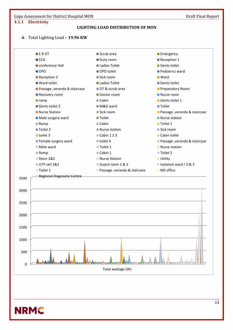
Gaps Assessment for District Hospital MON Draft Final Report
13
4.1.1 Electricity
LIGHTING LOAD DISTRIBUTION OF MON
Total Lighting Load – 19.96 KW
0
500
1000
1500
2000
2500
3000
3500
Total wattage (W)
E R OT Scrub area Emergency
ECG Duty room Reception 1
conference Hall Ladies Toilet Gents toilet
OPD OPD toilet Pediatrics ward
Reception 2 Sick room Ward
Ward toilet Ladies Toilet Gents toilet
Passage ,veranda & staircase OT & scrub area Preparatory Room
Recovery room Doctor room Nurse room
ramp Cabin Gents toilet 1
Gents toilet 2 M&G ward Toilet
Nurse Station Sick room Passage ,veranda & staircase
Male surgery ward Toilet Nurse station
Ramp Cabin Toilet 1
Toilet 2 Nurse station Sick room
toilet 3 Cabin 1 2 3 Cabin toilet
Female surgery ward toilet 4 Passage ,veranda & staircase
Male ward Toilet 1 Nurse station
Ramp Cabin 1 Toilet 2
Store 1&2 Nurse Station Utility
UTP cell 1&2 Guard room 1 & 2 Isolation ward ! 2 & 3
Toilet 1 Passage ,veranda & staircase MS office
Regional Diagnostic Centre

Gaps Assessment for District Hospital MON Draft Final Report
14
EQUIPMENT LOAD DISTRIBUTION OF MON
Total equipment Load – 72 KW
0
2000
4000
6000
8000
10000
12000
14000
16000
1
X ray machine 500 MA Dental [X-ray machine+Chair+Compressor+ Sterilizer]Autoclave (Dental) Small front Portable UltrasoundECG Machine computerized Cardiac Monitorinfusion pump NebulizerBaby Incubators Phototherapy UnitEmergency Resuscitation Kit- baby Radiant WarmerRoom warmer Foetal Dopplervacuum extractor metal Pulse Oximeter baby & adultRefrigerator Spot lampElectric Heater/Boiler Washing machine with dryer (Separate)Electronic fumigator Vertical AutoclaveFormalin Vaporizer CFL Phototherapywindow AC (1.5)/Split AC ILRDF Hub cuttersAuto clave HP Vertical (2 Bin) Operation Table Hydraulic MajorShadow less lamp stand model Focus lamp OrdinarySterilizer (Medium instruments) Diathermy Machine (Electric Cautery)Suction Apparatus- Electrical Lab incubatorElectric centrifuge, table Top Hematology AnalyzerBlood Bank Refrigerator Ordinary RefrigeratorAir conditioner with stabilizer Computer with UPS and printerAutomatic blood Gas Analyzer Gynae electric cauteryMTP suction apparatus Anesthesia machine with ventilatorO.H.P TV colorDVD player LCD ProjectorXerox machine Computer + printerSlit lamp Distance Vision chart

Gaps Assessment for District Hospital MON Draft Final Report
15
Emergency Equipment Load of MON
Emergency Equipment Load – 23.65 KW
A conservative approach has been taken and all the loads defined in the demand section may not be served. The
future demand may surpass the estimated supply which can later be catered by augmenting the plant size. A
detailed study and analysis of peak load, battery bank and grid analysis was done to serve additional loads over
and above the estimated supply.
Although apart from the below mentioned equipment the solar power can also be used to power the surface
pump & Treatment plant for an hour in case of grid failure or crisis situation. The capacity of power plant is
designed such that an additional load of 5 KW can be catered in emergency situation, but only as an auxiliary
power supply.
Imaging Equipment 60 M.A. X-Ray Machine (mobile) Specification discussed with Siemens 5000 Portable Ultrasound 1000 Cardio Pulmonary Equipment ECG Machine ordinary 350 Cardiac Monitor 150 Ventilator ( Adults) 650 Nebulizer 150 Labor ward, Neo Natal & Special Newborn Care Unit( SNCU) Baby Incubators(3) 450 Photo therapy Unit 150 Emergency Resuscitation Kit-Baby 450 Radiant Warmer (3) 2250 Suction Machine 320 Immunization Equipment ILR with stabilizer 550 DF with Stabilizer 650 OPD EQUIPMENT Dental Chair motorized with panel with compressor, ultrasonic scaler and suction & Filler 2300 OT Equipment Shadow less lamp ceiling type (major) 1500 Shadow less lamp ceiling type (minor) 500 Diathermy machine 4000 Sterilizer(Medium) 250 Suction Machine 1280 LAB EQUIPMENTS Hematology Analyzer with 22 parameters 250 Anesthesia Equipment Multi parameter Monitor 350 Infusion pumps 100 ADMIN Computer with modem with ups, printer & Internet connection 1000
TOTAL 23650

Gaps Assessment for District Hospital MON Draft Final Report
16
Electrical Works
Before recommending any change, a survey has to be conducted to identify distribution and grounding
problems, an initial physical site examination is recommended. It typically begins at the location of the sensitive
electronic load equipment and progresses back to the service entrance through the following sequence:
sensitive load equipment, branch circuit wiring, breaker panel, feeder wiring, main breaker panel,
switchboard, and service entrance.
Start at the load equipment to check the wiring for code violations, adequate insulation, visible damage,
miswired connectors (e.g., phase and neutral-reversed or phase sequence reversed); secure connections; and
measure the phase, neutral, and ground voltages and currents.
Verify that the breakers in the panel feed the sensitive electronic load. Check that no other loads are on a
dedicated circuit. Visually check for any code violations, the use of wire nuts, insulation, other visible damage,
and for secure connections. Look for signs of burnt areas or carbonization, which indicate previous faults,
flashovers, arcing, etc. Note the size of incoming and outgoing conductors and make sure that they are
adequately sized for the load, especially the neutral. Check for shared neutrals and possible overloads with high
harmonic loads. Check the temperature of the insulated face of circuit breakers and for visual signs of
overheating. Smell the panel, which may indicate overheating conditions. Measure phase, neutral, and ground
voltages and currents, as well as the voltage drop across each critical breaker. More than about 0.1-V indicates
a possibly bad unit. Look for signs of previous faults such as burnt areas, flashovers, arcing, etc. Note the size of
incoming and outgoing conductors. Check for visual signs of overheating. Use an infrared camera, if available,
for examining the hot spots in the main breaker panel and switchboard.
Measurements of load-phase current and neutral current are necessary to determine whether the load is
sharing a neutral conductor with other loads. They also determine whether the neutral conductor sizing is
adequate. When sizing neutral conductors, remember that the current in the neutral can exceed current in the
phase conductor in three-phase circuits supplying single-phase loads with nonlinear current characteristics. A
true RMS reading clamp-on ammeter must be used to make phase and neutral conductor measurements. To
determine whether the neutral serving the sensitive electronic load is shared with other loads, check the
neutral current with the sensitive load turned off. If the current is not zero, a shared neutral is being used.
Panel description, feeder description, branch circuit loads, branch circuit voltage, branch circuit currents and
other above mentioned details once compiled can make it easy for implementation of Re-wiring or Renovation
work of complete electrical system at the district hospital.

Gaps Assessment for District Hospital MON Draft Final Report
17
Servo Stabilizer
The Servo Stabilizers uses an advanced electronic servo-motor concept to control a motorized variable
transformer. Because of the motorization, there is a small delay in voltage correction. However, output voltage
accuracy is usually ± 1% with input voltage changes up to ± 50%. These machines are not affected unduly by
power factor or frequency variation. This type of technology tends to be extremely effective when considering
large three phase applications, as it is able to maintain its accuracy of all three phases, both line to line and line
to neutral, irrespective of input voltage balance and load balance at any power factor. They are also able to
withstand large inrush currents, normally experienced with inductive loads. However due to the mechanics of
this type of stabilizer, periodic maintenance is required.
Various Design Topologies:-
Single Phase Input & Single Phase Output
Three Phase Input & Three Phase Output (Balanced Load)
Three Phase Input & Three Phase Output (Unbalanced Load)
Inverter & Battery Backup for Emergency
A typical power inverter device or circuit requires a relatively stable DC power source capable of supplying enough current for the intended power demands of the system. The input voltage depends on the design and purpose of the inverter.
A power inverter device which produces a multiple step sinusoidal AC waveform is referred to as a sine wave inverter. To more clearly distinguish the inverters with outputs of much less distortion than the modified sine wave (three step) inverter designs, the manufacturers often use the phrase pure sine wave inverter. Almost all consumer grade inverters that are sold as a "pure sine wave inverter" do not produce a smooth sine wave output at all, just a less choppy output than the square wave (two step) and modified sine wave (three step) inverters. However, this is not critical for most electronics as they deal with the output quite well.
Where power inverter devices substitute for standard line power, a sine wave output is desirable because many electrical products are engineered to work best with a sine wave AC power source. The standard electric utility provides a sine wave, typically with minor imperfections but sometimes with significant distortion.
Sine wave inverters with more than three steps in the wave output are more complex and have significantly higher cost than a modified sine wave, with only three steps, or square wave (one step) types of the same power handling. Switch-mode power supply (SMPS) devices, such as personal computers or DVD players, function on quality modified sine wave power. AC motors directly operated on non-sinusoidal power may produce extra heat, may have different speed-torque characteristics, or may produce more audible noise than when running on sinusoidal power.

Gaps Assessment for District Hospital MON Draft Final Report
18
OFF GRID SOLAR POWER PLANT
PV systems have been the focus of numerous efforts for rural electrification. The panels themselves typically have a very long lifetime (20-30 years). Unfortunately, installation programs do not always include a sufficient service component. Regular maintenance on batteries is essential while training local hospital staff in system maintenance is essential for routine maintenance; a professional technician should also perform an annual maintenance check, examining wiring connections, mounting bolts, and inverter operation.
PV systems typically have higher capital costs, but lower operating costs when compared to other energy generation options. The availability of replacement components (model and brand) from local vendors should be considered when procuring initial system components. End-user expectations of solar systems are often unrealistic – education on the practical application of solar systems must accompany system design and installation. National standards for the placement, design, procurement, installation, and servicing of Photovoltaic systems can help improve sustainability. Donor-funded PV systems often fail for lack of operating funds and local service infrastructure. Detailed user manuals are critical – especially in cases where staff turnover is high. Local ownership, often established through a contribution to initial system cost, is critical for system sustainability.

Gaps Assessment for District Hospital MON Draft Final Report
19
SPV Modules
a. Modules of Hybrid Power Plant shall be made of poly crystalline Silicon Solar Cells.b. Each module shall have low iron tempered glass in front for strength and superior light transmission. It
shall have back sheet for environment protection against moisture and high voltage electrical insulation.c. The module frame shall be made of aluminium or corrosion resistant material, which shall be electrically
compatible with the structural material used for mounting the modules.d. Solar module shall be laminated using lamination technology using established polymer (EVA) and
Tedlar/Polyester laminate. The solar module shall have suitable encapsulation and sealing arrangements toprotect the silicon cells from the environment. The arrangement and the material of encapsulation shall becompatible with the thermal expansion properties of the Silicon Cell and the module framingarrangement/material. The encapsulation arrangement shall ensure complete moisture proofing during lifeof solar modules.
e. Individual Solar Module rating shall not be less than 200W at standard test conditions. Test reports of themodules should be submitted with the technical bid.
f. Power output Guarantee offered for the SPV Module shall not be less than 25 years.g. The modules would be warranted for output wattage not less than 90% at the end of 10 years and 80% at
the end of 25 years.h. SPV module conversion efficiency should be greater than 14%.i. Peak Power Point Voltage and Peak Power Point Current of any supplied module and /or any module string
(series connected module) shall not be more than 3% from the respective arithmetic means for the entiremodule and/or for all module strings, as the case may be.
j. Module rating is considered under standard test conditions, however Solar Modules shall be designed tooperate and perform relative humidity up to 100% with temperature between 0o C and +50o C and withgust up to 150km/hr from backside of the panel. the geological data for each health centre location ofNagaland from standard source can be referred for design to get optimum generation.
k. Sample modules and production processes employed in the manufacture of the offered module shall be inaccordance with the requirements of IEC 61215/ IS14286 and IEC61730 Part-I & Part-II with appropriatecertificate. IEC / equivalent BIS Equivalent IS Standards
l. PV modules to be used in a highly corrosive atmosphere (coastal areas, etc.) must qualify Salt MistCorrosion Testing as per IEC 61701 / IS 61701.

Gaps Assessment for District Hospital MON Draft Final Report
20
Array Structure
Structures shall be of flat-plate design either I or L sections. Structural material shall be corrosion resistant and electrolytically compatible with the materials used in the module frame, its fasteners, nuts and bolts. Galvanizing should meet ASTM A-123 hot dipped galvanizing or equivalent which provides at least spraying thickness of 70 microns on steel as per IS5905, if steel frame is used. Aluminum frame structures with adequate strength and in accordance with relevant BIS/ international standards can also be used. Structures shall be supplied complete with all members to be compatible for allowing easy installation at the rooftop site. The structures shall be designed to allow easy replacement of any module & can be either designed to transfer point loads on the roof top or UDL as per site conditions. Each structure shall have a provision to adjust its angle of inclination to the horizontal as per the site conditions. Each panel frame structure is so fabricated as to be fixed on the ground or roof. The structure should be capable of withstanding a wind load of 200 km/hr after grouting & installation. The front end of the solar array must be one meter above the ground. Grouting material for SPV structure shall be as per M15 (1:2:4) concrete specification. The structures shall be designed for simple mechanical and electrical installation. There shall be no requirement of welding or complex machinery at the installation site. If prior civil work or support platform is absolutely essential to install the structures, the supplier shall clearly and unambiguously communicate such requirements along with their specifications in the bid. Detailed engineering drawings and instructions for such prior civil work shall be carried out prior to the supply of Goods.
The supplier shall specify installation details of the PV modules and the support structures with appropriate diagrams and drawings. Such details shall include, but not limited to, the following:
Determination of true south at the site; Array tilt angle to the horizontal, with permitted tolerance; Details with drawings for fixing the modules; Details with drawings of fixing the junction/terminal boxes; Interconnection details inside the junction/terminal boxes; Structure installation details and drawings; Electrical grounding (earthing); Inter-panel/Inter-row distances with allowed tolerances; and Safety precautions to be taken. The array structure shall support SPV modules at a given orientation
and absorb and transfer the mechanical loads to the rooftop columns properly. All nuts and boltsshall be of very good quality stainless steel.

Gaps Assessment for District Hospital MON Draft Final Report
21
PCU
A solar inverter, or converter or PV inverter, converts the variable direct current (DC) output of a photovoltaic (PV) solar panel into a utility frequency alternating current (AC) that can be fed into a commercial electrical grid or used by a local, off-grid electrical network. It is a critical balance of system (BOS)–component in a photovoltaic system, allowing the use of ordinary AC-powered equipment. Solar power inverters have special functions adapted for use with photovoltaic arrays, including maximum power point tracking and anti-islanding protection.
Protections required in the PCU:
o Mains (Grid) over-under voltage and frequency protectiono Full proof protection against Islanding.o Included authentic tracking of the solar arrays maximum power operation voltage (MPPT).o Array ground fault detection.o LCD and piezoelectric keypad operator interface menu driveno Automatic fault conditions reset for all parameters like voltage, frequency and/or black out.o MOV type surge arresters on AC and DC terminals for over voltage protection from lightning-
induced surges.o PCU should be rated to operate at 0 -55 deg. Centigrade unless provision for air conditioning is
included in PCUo All parameters should be accessible through an industrial standard communication link.
Total Energy Consumption KW Units usage
Lighting Load MON & Energy Consumption 19.96 359.28
(Lighting Load can be catered for 6 hours)(3 days autonomy in case of bad weather & Grid failure) Total Units Required (60 % Load Utilization) 11.976 215.56
Total Energy Consumption
Emergency category Equipment Loads MON DC 23.65 189.2
(All emergency equipment operational for 4 hours) (2 Days Autonomy in case of bad weather & Grid failure) Total Units Required (60 % Load Utilization) 14.19 113.52
Total Number of Units Required to be generated to suffice the requirements 329.08
Solar Insolation In MON 4.35
Total Units Generation required 329.08
Capacity Of Solar Power plant required for the required Load (76KW) 80 KWP
Rough estimation of area required for Solar Power Plant Installation of the above mentioned capacity
8000 sq. feet
Monthly Energy Consumption 9872.64 KWH
Yearly Energy Consumption 120117 KWH
Generation Loss due to Maintenance & Service issues (12 days/yr.) 330 KWH/month
Generation Loss due to Bad Weather (36 days/yr.) 990 KWH/month
Total Effective Units Generated (Annual) 104277 KWH

Gaps Assessment for District Hospital MON Draft Final Report
22
SOLAR WATER HEATER
A 100 LPD Solar Water Heating (SWH) System having 2 square meter of collector area, can replace an electric geyser of 2 KW capacities for residential use and may save up to 1,500 units of electricity and up to 1.5 tons of CO2 per year depending upon the location of installation. The gross potential for solar water heating systems in India has been estimated to be about 140 million sq. m. of collector area. However, we have achieved about 12 million sq. meter collector areas. There is a lot of potential for Solar Water Heating Systems in the country.
Hot water usage in Hospitals
Water for drinking Water for housekeeping Cooking water supply Preheated water for the use of sterilizing equipment in autoclave machines. Fulfillment of hot water required in new born care unit & labor rooms.
The main objective of the program is to promote the widespread use of solar water heaters in the country through a combination of financial and promotional incentives, and other support measures so as to conserve electricity and other fossil fuels, apart from peak load saving in cities and towns.
Heating water is very expensive as it requires a huge amount of energy. It is believed that 18% of domestic energy is used to heat water. In most homes and businesses this energy is generated from fossil fuels – gas and oil. Most modern domestic boilers will run on gas and heat water on demand. But many people still heat their water using electricity which is the most expensive way to heat water. Simple calculations on the energy output, savings on LPG and reduction of CO2 have been conducted. Preliminary results indicated that the saving on LPG based on proposed system was more than 20%. With a prospect of 100+ health facilities throughout the state, this project shall improve public awareness in energy conservation in the hot water production of their buildings and increase the market of the solar energy systems
Solar thermal panels can only heat water and it requires space on roof top. Annual maintenance is recommended.
Incorporating the Solar Hot Water System to the commercial hot water system heated by LPG boilers, there
would be a large potential in energy saving and greenhouse emission reduction.

Gaps Assessment for District Hospital MON Draft Final Report
23
SOLAR STREET LIGHTS
Solar street lights are independent of the utility grid resulting to lessened operation costs.
Solar street lights require lesser maintenance than conventional street lights. These have lower chances of
overheating. Since solar wires do not have external wires, the risk of accidents is minimized.
Solar street lights are environment-friendly because its panels are solely dependent to the sun hence
eliminating your carbon footprints contribution. Some parts of solar street lighting systems can be easily
carried to remote areas making these more efficient and handy solutions to lighting problems. Lighting up
streets and roads enhance the comfort, security and overall safety of our rapidly growing urban environments.
Standalone solar street lighting is designed to achieve better light uniformity and maximum spacing between poles for both pedestrian and vehicle road applications, and higher efficiency to save panel size and battery capacity in solar lighting system. With its die-cast aluminum housing, it is easy to maintain, has a long lifetime and a consistency you can count on.
Light Source The light source will be a white LED type. Single lamp or multiple lamps can be used. The colour temperature of white LED used in the system should be in the range of 5500K–6500K. Use of LEDs which emits ultraviolet light is not permitted. The light output from the white LED light source should be constant throughout the duty cycle. The lamps should be housed in an assembly suitable for outdoor use. The temperature of heat sink should not increase more than 20oC above ambient Temperature even after 48 hours of continuous operation. This condition should be complied for the dusk to dawn operation of the lamp while battery operating at any voltage between the load disconnect and the charge regulation set point. The make, model number, country of origin and technical characteristics (including IESNA LM-80 report) of white LEDs used in the lighting system must be furnished to the Test Centers and to the buyers. In absence of this data the solar street lights may not be tested by the Test Center.
Battery Lead Acid, Tubular Positive Plate Flooded or Tubular GEL / AGM VRLA, 12 V- 40 AH @ C/10 discharge rate. Battery should conform to latest BIS standards. In view of non-availability of adequate test facilities for testing as per BIS standard in the country, existing facilities of battery manufacturers will be utilized by way of periodic quality audit by MNRE/BIS or their representative to ensure conformance of BIS standards. (i) Also initially for a period of six months from the date of the issue of these guidelines capacity test, Ampere-Hour (Ah) & Watt-Hour (Wh) Efficiency test and charge retention tests per BIS standards may be used to enable the program to continue. (ii) It is also mandatory for the battery manufacturers/ bulk users to comply with batteries (Management and handling) Rules 2001 of MOEF, as amended. (iii) The manufacturer is required to submit the test report on Ah efficiency Wh efficiency and charge retention test from an NABL accredited Lab Whereas the capacity test of the battery will be conducted by the system testing lab. (iv) At least 75 % of the rated capacity of the battery should be available between fully charged & load cut off conditions.
Electronics (i) The total electronic efficiency should be at least 85%.

Gaps Assessment for District Hospital MON Draft Final Report
24
(ii) Electronics should operate at 12 V and should have temperature compensation for proper charging of the battery throughout the year. (iii) The light output should remain constant with variations in the battery voltages.
Pv module The PV module (s) shall contain mono/ multi-crystalline silicon or thin film solar cells. In case of crystalline silicon solar cell module it is required to have certificate for the supplied PV module as per IEC 61215 specifications or equivalent National or International Standards whereas in case of thin film solar cell module it is required to have certificate for the supplied PV module as per IEC 61646 specifications or equivalent National or International Standards. In case of thin film modules for each model the modules should fulfill the wattage criterion after light soaking degradation. In case the supplied PV module is not a module of regular production of the manufacturer and does not have certificate as above then the manufacturer should have the required certification for at least one of the irregular modules. Further, the manufacturer should certify that the supplied module is also manufactured using same material design and process similar to that of certified PV module. In case of imported modules it is mandatory to provide a copy of the international product qualification certificate to the test center.
Solar Pump
A solar energy-powered water pump is a water pump running on the electricity that is generated by solar photovoltaic modules. Using solar energy as power source, such solar water pumps basically consist of three main components:
Water pump Solar Photovoltaic modules Pump controller (and inverter)
According to the water table level, distance to move the water and the pumping quantity requirements, different type sizes of water pumps apply. Shallow-well water pumping requirements are different from those for deep-well water pumping.
Water is a precious resource. Wastage needs to be minimized It is important for hospitals to monitor its water usage Safe and adequate water is essential for effective hospital infection control and monitoring its
microbiological quality is of paramount importance Water for drinking Water for housekeeping Cooking water supply Water for Sterilization and cleaning of equipment and use in hospital laundry
Water Situation 1 Bore well available, rain water harvesting available. No running water 4 RCC rain water storage tanks 2 steel rain water storage tanks 3 RCC pipe type rain water storage tanks 5 Overhead tanks – 3 located on top of OPD Building and 2 located on Admin building.

Gaps Assessment for District Hospital MON Draft Final Report
25
The district is basically a hilly one. Geomorphologically, the district comprises of high hills with steep gorges and limited intermontane valley. The foot hills lie adjacent to the plains of Assam i.e., the Tizit and Naganimora areas. Thus, the development of ground water is limited in nature. Moreover, logistic support in terms of approachable road and non-availability of valley areas are one of the main hindrances to ground water development.
Solar Surface Pump & Solar Submersible Pump
During hot months and in hot areas the requirement for water is high. Solar water pumps are electrically driven pumping systems, powered by photovoltaic panels. Solar water pumps use the generated electricity to pump water. According to each individual need, solar water pumps can be applied for following purposes where pumping water is needed:
Solar Surface Pump Indicative Technical Specification of Shallow Well (Surface) Solar Pumping Systems With D.C. Motor Pump Set with Brushes or Brush Less D.C. (B.L.D.C.) Description
Model-I Model-II Model-III
PV array 900 Wp 1800 Wp 2700 Wp Motor capacity 1 hp 2 hp 3 hp Shut Off Dynamic Head 12 meters 12 meters 12 meters Water output* 90,000 liters per day
from a total head of 10 meters
140,000 liters per day from a total head of 10 meters
135,000 liters per day from a total head of 20 meters

Gaps Assessment for District Hospital MON Draft Final Report
26
5. CONCLUSIONS & RECOMMENDATIONS
There are few drawings and survey reports required for complete implementation. Determine condition and adequacy of the wiring and grounding system. Determine ac voltage quality at the point of use Determine sources of power disturbances and their impacts of power disturbances on equipment
performance Analyse findings to identify immediate and long-term cost-effective solutions. Structure Design work for Solar Power Plant requires approval by Civil & Structural Engineer.
NOTE**In absence of electrical single line diagram and in absence of any details to calculate thecosting of the electrical works in the facility. The costing has been done on the basis of
assumptions, of rate per square feet area. The rates have been discussed with the building
contractors working in the North-eastern region and cost estimate has been prepared and
provided. The cost estimate per square feet includes products from mentioned companies
[Polycab, Havells, KEI, L&T, C&S] **
As per the annexure attached, CPWD DELHI Govt. rates, the calculation can be done only on the
basis of number of points that can be calculated on the basis of single line diagram. Please find
the annexure attached with the document for the CPWD rates. In absence of any diagram and no
detail of number of points, Just area wise costing is estimated for electrical works.
Categories Recommendations
Grid Power No Recommendation
Power Availability 4 Stages of Power Supply Required. Solar + Grid + Inverter + Generator
Wiring No changes Recommended
Generator Installation required for 125 KVA. 25 Kva has to be repaired. 7.5 KVA has to be repaired.
Transformer Required - 125 KVA
Inverter Inverters to be serviced, Batteries to be replaced. Back up duration less
Solar water Heater Installation of SWH (FPC) 1000litres
Water Pump 2 Surface Pumps to be installed. One running & One standby. Normal electric pumps recommended not a solar pump.
Area & Compound Lighting
20 Solar Led Street Lights for Illumination of outdoors and Energy Efficient Led Lighting required in corridors and rooms to reduce the lighting load.

Gaps Assessment for District Hospital MON Draft Final Report
27

Gaps Assessment for District Hospital MON Draft Final Report
29
ANNEXURE I : LIST OF DOCUMENTS REFERRED
Glossary & Abbreviations [Containing Definitions, Expansion Of Abbreviations In Cerc/Sercs ] Benchmark cost for “Off Grid & Decentralized Solar PV application programme. MNRE order -
5/23/2009 – P&C (Pt.III) dated 3rd Nov 2014 Technical data specification sheet of Siemens Mobile X-ray machine with 2.5 kW HF generator for
general use, mobile single-tank, diagnostic X-ray system National Solar Mission MNRE. Annual Report (2016-17) MNRE Empanelled list of SPV suppliers and their respective specifications. MNRE Empanelled list of SWH suppliers and their respective specifications. MNRE Empanelled list of Solar Powered Pumps suppliers and their respective specifications. MNRE Empanelled list of Standalone Street Lights suppliers and their respective specifications. Satec Envir Engineers specification for Control Panel Room & Mounting Structure. Emmvee Swh Brochure Emmvee SWH Quotation Emmvee SPV Brochures Emmvee SPV Quotation CPWD Wiring rates 2016 for Delhi Govt.

Gaps Assessment for District Hospital MON Draft Final Report
30
ANNEXURE II : LIST OF PEOPLE MET
Dr Yanang

Gaps Assessment for District Hospital MON Draft Final Report
31
ANNEXURE III : TERMS OF REFERENCE
Renewable Energy Expert
Base location: Kohima
Development of Questionnaires and Field Assessment Methodology
Site Visits and Data Collection
Technical Evaluation for Health Centres
Preparation of Detailed Project Report along with technical specifications, cost estimates for the sites.

Wokha District Hospital DPR

Gaps Assessment for District Hospital WOKHA Draft Final Report
GAPS ASSESSMENT REPORT
NAGALAND
DISTRICT HOSPITALS

Gaps Assessment for District Hospital WOKHA Draft Final Report
LIST OF ABBREVIATION S
Abbreviations Full Name
CEA Central Electricity Authority
GRID Means High Voltage Backbone System Of Interconnecting Transmission Lines, Substations And Generating Plants
DPR Detailed Project Report
DEVELOPER Entity Which Develops Project
AFC Annual Fixed Cost
CAPTIVE USER End User Of The Electricity Generated In A Captive Generating Plant
RENEWABLE ENERGY/ POWER
Means The Grid Quality Energy/Power Generated From Renewable Energy Sources
RENEWABLE ENERGY SOURCES
Renewable Sources Such As Solar In This Case Including Its Integration With Combined Cycle, Biomass, Bio Fuel Cogeneration, Urban/Municipal Waste And Other Such Sources As Approved By The MNRE
SOLAR PV POWER The Solar Photo Voltaic (PV) Power Project That Uses Sunlight For Direct Conversion Into Electricity Through Photo Voltaic Technology.
SOLAR THERMAL POWER Solar Thermal Power Project That Uses Sunlight For Direct Conversion Into Electricity Through Concentrated Solar Power Technology Based On Either Line Focus Or Pointy Focus Principle.
ETC Evacuated Tube Collector
FPC Flat Plate Collector
SPV Solar Photovoltaic
SPP Solar Photovoltaic Pump
AH Ampere Hour
KWH-DAY Kilo Watt Hour Per Day
KWH/M2 Kilo Watt Hour Radiation Per Square Meter Area
KVA Kilo Volt
KV Kilo Volt Ampere
KWH Kilo Watt Hour
MW Mega Watt
WP Watt Peak
LED Light Emitting Diode
APAC Asia-Pacific or Asia Pacific
CHC Community Health Centre
PHC Primary Health Centre

Gaps Assessment for District Hospital WOKHA DRAFT FINAL REPORT
iii
Table of Contents
List of Abbreviations ....................................................................................................................................................... ii
1. About the PROJECT ................................................................................................................................................ 4
2. Objectives of the assignment ............................................................................................................................. 7
3. Methodology ............................................................................................................................................................. 8
3.1 Process Flow .......................................................................................................................................................... 8
3.2 Checklist /Key Information Areas ................................................................................................................. 9
4. Findings from Hospital Assessment ............................................................................................................. 10
4.1 Current Status on Infrastructure and Gaps ...................................................................................... 10
4.1.1 Electricity .............................................................................................................................................. 13
5. CONCULSIONS, RECOMMENDATIONS AND COSTING .......................................................................... 31
Annexure I:LIST OF DOCUMENTS REFERRED ................................................................................................... 34
Annexure II: LIST OR PEOPLE MET ........................................................................................................................ 35
Annexure III: TERMS OF REFERENCE ................................................................................................................... 36

Gaps Assessment for District Hospital WOKHA DRAFT FINAL REPORT
4
1. ABOUT THE PROJECT
NAGALAND HEALTH PROGRAM
Of all seven sisters in North Eastern India, each state has their distinct features which differentiate them from each other.
Assam and Tripura, which is rich in petroleum resources, Arunachal Pradesh has a hydro power potential of 50000 MW according to CEA. Meghalaya has coal and uranium resources, while Mizoram has rich Biomass, Sikkim and Nagaland also have hydro potential. Nagaland has a huge potential to generate power from solar installations. Non Renewable Energy "A non-renewable resource is a natural resource that cannot be re-made or re-grown at a scale comparable to its consumption”.
Coal Petroleum Natural Gas Limited
Source: Coal, petroleum, and natural gas are considered non-renewable because they cannot be replenished in a short period of time. "Renewable Energy is energy that is derived from natural processes that are replenished constantly. In its various forms, it derives directly or indirectly from the sun.”
These are called fossil fuels. As per the increasing energy demand, we have to look after the renewable sources of energy to meet the demand. Environmental hazard: Using these sources of energy causes hazardous damage to the environment leading to effects of global warming, acid rain, carbon dioxide emission, health hazards and other impacts.
Anticipated demand of the state by the end of 2020, could be 500MW. To meet the requirement, the department has been exploring ways and means to harness different sources of energy in the state, the report said. During the current financial year (as on February 2011), 24MW Likimro Hydro Electric Project has generated 60.72 MU which has supplemented the state’s power requirement as well as resources to a large extent. 1MW Lang Hydro Electric Project is scheduled to be completed in 2012 while 1 MW Tehok Hydro Electric Project is scheduled to be completed by 2012-13.

Gaps Assessment for District Hospital WOKHA DRAFT FINAL REPORT
5
Overview of North Eastern Electric Power Corporation Limited (NEEPCO) Executed Projects :- Total - 275 MW
Kopili Hydro Electric Power Plant. Comprises of three power stations (North Cachhar Hills District, Assam)
o Khandong power station (2x25 MW) – 50 MW o Kopili power station (2x50 MW + 2x50 MW) – 200 MW o Kopili power station, Stage-II (1x25 MW) – 25 MW
Ranganadi Hydro Electric Project – Arunachal Pradesh – biggest power plant – 405 MW Doyang Hydro Electric Project – Nagaland – 75 MW Assam Gas Based Power Plant – 291 MW – Combined cycle power station comprising 6 gas and 3 steam
turbines Agartala Gas Turbine Plant – 84 MW – Open cycle with 4 gas turbines
Projects under execution
Kameng Hydro Electric Project – 600 MW – Run of the river scheme Pare Hydro Electric Project – 110 MW – Run of the river scheme on river Dikrong Tuirial Hydro Electric Project – Mizoram – 60 MW Tripura Gas Based Power Project – 100 + 20 MW at Monachak, Tripura – scheduled for commissioning
by July, 2013 Covering an area of 1,628 sq. km, Wokha is located in the mid-western part of Nagaland. It is bounded
by Assam in the West and North, Kohima and Dimapur district in the South, Zunheboto in the East and Mokokchung in the North-East. In terms of area, it represents 9.82 per cent of the total area of the state of Nagaland (16,579 sq.km) and occupies the 5th place among the eleven districts of the state. The main rivers in Wokha district are Doyang, Chubi, Nruk and Nzhu. The district belongs to Brahmaputra basin and Dhansiri and Disang sub-basin.

Gaps Assessment for District Hospital WOKHA DRAFT FINAL REPORT
6
DOYANG is the largest river in the District and there is a Hydro Electric Station with a capacity of 75MW called Doyang Hydro Project which is located across the Doyang River. Although Doyang Hydro Electric Project – the entire plant was taken over by the central government while Nagaland receives only a mere 12% in royalty. Out of the 75 megawatt (MW) of electricity generated in the DHEP, Nagaland receives only 7 MW. Wokha district, declared as 'the land of plenty', by the state government of Nagaland, due to her rich mineral resources, soil fertility and abounding flora and fauna. Wokha is the third largest town in Nagaland after Dimapur and Kohima.
Potential Of Hydro Electric Power Plant In Nagaland – 1574 MW Current Installed Capacity – 75 MW
Climate, Demography & Population
Category DISTRICT HOSPITAL CHC PHC SUB CENTRE
Wokha 1 2 12 37
Category Demography
Wokha
Villages Blocks Rural Population
150 7 166343
Average Metrological Data of the Sites WOKHA Rainfall (in mm) 2123.4 Elevation (in m) 1360 Latitude 26.074 N Longitude 94.259 E Solar Insolation 4.35 Kwh/m2/day Wind Speed 10.01 km/hr. Sunrise Time 4.46 A.M. Sunset Time 4.58 P.M. Average annual daylight hours 12hrs 12 minutes Maximum Temperature 32 degrees Minimum Temperature 7 degrees
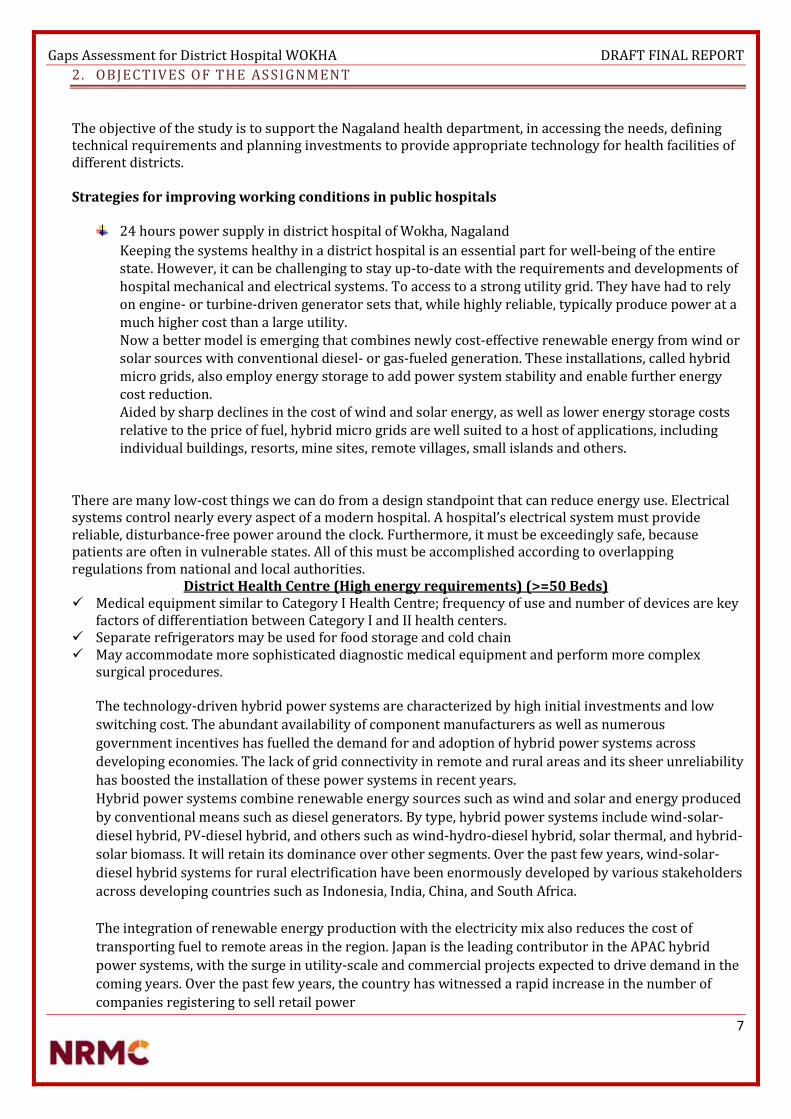
Gaps Assessment for District Hospital WOKHA DRAFT FINAL REPORT
7
2. OBJECTIVES OF THE AS SIGNMENT
The objective of the study is to support the Nagaland health department, in accessing the needs, defining technical requirements and planning investments to provide appropriate technology for health facilities of different districts. Strategies for improving working conditions in public hospitals
24 hours power supply in district hospital of Wokha, Nagaland
Keeping the systems healthy in a district hospital is an essential part for well-being of the entire state. However, it can be challenging to stay up-to-date with the requirements and developments of hospital mechanical and electrical systems. To access to a strong utility grid. They have had to rely on engine- or turbine-driven generator sets that, while highly reliable, typically produce power at a much higher cost than a large utility. Now a better model is emerging that combines newly cost-effective renewable energy from wind or solar sources with conventional diesel- or gas-fueled generation. These installations, called hybrid micro grids, also employ energy storage to add power system stability and enable further energy cost reduction. Aided by sharp declines in the cost of wind and solar energy, as well as lower energy storage costs relative to the price of fuel, hybrid micro grids are well suited to a host of applications, including individual buildings, resorts, mine sites, remote villages, small islands and others.
There are many low-cost things we can do from a design standpoint that can reduce energy use. Electrical systems control nearly every aspect of a modern hospital. A hospital’s electrical system must provide reliable, disturbance-free power around the clock. Furthermore, it must be exceedingly safe, because patients are often in vulnerable states. All of this must be accomplished according to overlapping regulations from national and local authorities.
District Health Centre (High energy requirements) (>=50 Beds) Medical equipment similar to Category I Health Centre; frequency of use and number of devices are key
factors of differentiation between Category I and II health centers. Separate refrigerators may be used for food storage and cold chain May accommodate more sophisticated diagnostic medical equipment and perform more complex
surgical procedures. The technology-driven hybrid power systems are characterized by high initial investments and low
switching cost. The abundant availability of component manufacturers as well as numerous
government incentives has fuelled the demand for and adoption of hybrid power systems across
developing economies. The lack of grid connectivity in remote and rural areas and its sheer unreliability
has boosted the installation of these power systems in recent years.
Hybrid power systems combine renewable energy sources such as wind and solar and energy produced
by conventional means such as diesel generators. By type, hybrid power systems include wind-solar-
diesel hybrid, PV-diesel hybrid, and others such as wind-hydro-diesel hybrid, solar thermal, and hybrid-
solar biomass. It will retain its dominance over other segments. Over the past few years, wind-solar-
diesel hybrid systems for rural electrification have been enormously developed by various stakeholders
across developing countries such as Indonesia, India, China, and South Africa.
The integration of renewable energy production with the electricity mix also reduces the cost of
transporting fuel to remote areas in the region. Japan is the leading contributor in the APAC hybrid
power systems, with the surge in utility-scale and commercial projects expected to drive demand in the
coming years. Over the past few years, the country has witnessed a rapid increase in the number of
companies registering to sell retail power

Gaps Assessment for District Hospital WOKHA DRAFT FINAL REPORT
8
3. METHODOLOGY
3.1 Process Flow
Data collection for the systematic review was done by extracting relevant research studies from the site surveys by various technical experts. Data extraction allowed the researchers to determine which data was most important in answering the problems faced by various staffs at the hospital. The poor working conditions are attributed to poor infrastructure, inadequate resources, lack of safety and security, poor interpersonal relationships, lack of involvement in decision making and lack of support from governing body. The study revealed that effective management at hospital level may create an enabling working environment modifying the impact of resource shortfalls. The complete area was surveyed, MS and staffs took us around the entire area, explained few things what they go through because of the poor infrastructure facilities and policies. The area was studied; proper checklist sheet was worked on as per the data available. There were certain parameters which were not available, few things were not even known to the staffs.
Site analysis of the hospital. The feasibility for solar in that area The availability of space for the necessary installation. The availability of grid & other alternate supplies.
Each and every small detail was considered and every site was not only surveyed but also analysed, worked upon, to finally prepare the draft.

Gaps Assessment for District Hospital WOKHA DRAFT FINAL REPORT
9
3.2 Checklist /Key Information Areas
Location (District, State) WOKHA
Latitude 26.074 N
Longitude 94.259 E
Age of Building Old (50 Years), New (0-10 Yrs.)
Roof Type Purlin Asbestos (50 Years Old) RCC Roof Top, 5 Structures With Rough Area Of 2000 Sq. Feet Per Structure
No. of Floor to terrace 36 Feet/24 Feet/12 Feet
Height of terrace from ground level G+1
Exact location of the solar power plant New Super Structure construction for Mounting SPV modules
Load bearing capacity of terrace Admin, X Ray & LAB Buildings Only Suitable (Need To Be Checked With Civil & Structural Engineer)
Soil Type Rocky
Transformer Make & Rating if available Not Available
Transformer Age Not Available
DG availability Yes - 125 Kva Kirloskar Generator Sets
Current Power Scenario 8
Electricity Tariff Not Available
Proposed Storage Area for Inverter and Batteries Admin Building Or New Control Panel To Be Constructed
Risk of flooding during monsoons No
Land clearing requirements IF any Yes For Ground Mounting & Super Structure(Need To Be Checked With Civil Engineer)
Transportation Issues & dependencies Cost Medium
Is Emergency electric supply available for the system Yes
Exact location of the solar water heater Opd building
Load bearing capacity of terrace for SWH Yes
Whether the solar systems will be installed will there be shadow?
No
Cold water supply to use points Gravity
Present mode of heating Boiler Electric Or Gas
Average Monthly expenditure on fuel Rs. Not Available
Is there a hot water distribution system already in existence?
No
Type of Collector to be Installed Fpc type
Required Capacity to be installed at WOKHA DH 500 Litres

Gaps Assessment for District Hospital WOKHA DRAFT FINAL REPORT
10
4. FINDINGS FROM HOSPITAL ASSESSMENT
4.1 Current Status on Infrastructure and Gaps
From this survey, it is clear that provision of a positive working environment is crucial for the wellbeing of the employees, the patients as well as the organisation. In facilities experiencing equipment problems that appear to be power related, on-site surveys generally are required in order to verify that power disturbances are the cause of electronic equipment malfunction or failure. Re-Wiring problems listed are detectable through effective testing and analysis of the wiring and grounding system. Provision of adequate infrastructure is of high importance. Mechanical and electrical systems act as vital organs to a hospital, providing power, water, fresh air and other important elements that keep the hospital running efficiently and safely. Please find the infrastructure requirements of a district hospital and also do go through the Findings at the site.
Categories Findings
Grid Power 3phase Power
Power Availability Power Availability – 8 hours (Average) (Weather Issues, At Times No Power For 15 days)
Wiring Old Building wiring has to be changed.
Generator Kirloskar - 125 Kva (Not working)
Transformer 125 KVA required
Inverter Inverter Battery Set – 4 Sets
Portable Generator set 1 Set – Non working
Solar water Heater No water heater
Water Situation One Bore well available, rain water harvesting available. No running water. RCC rain water storage tanks, steel storage tanks. Overhead tanks limited.
Area & Compound Lighting T8 Tube lights & maximum Incandescent bulb available

Gaps Assessment for District Hospital WOKHA DRAFT FINAL REPORT
11
IPHS GUIDELINES Hospital Building – Planning and Lay out Appearance and upkeep There shall be provision of adequate light in the night so hospital is visible from approach road. Signage The building should have a prominent board displaying the name of the Centre in the local language at the gate and on the building. Signage indicating access to various facilities at strategic points in the Hospital for guidance of the public should be provided. Florescent Fire Exit plan shall be displayed at each floor. Roads shall be illuminated in the nights Environmental friendly features The Hospital should be, as far as possible, environment friendly and energy efficient. Rain-Water harvesting, solar energy use and use of energy-efficient bulbs/ equipment should be encouraged. Provision should be made for horticulture services including herbal garden. Intensive Care Unit and High Dependency Wards General Location This unit should be located close to operation theatre department and other essential departments, such as, X-ray and pathology so that the staff and ancillaries could be shared. Easy and convenient access from emergency and accident department is also essential. This unit will also need all the specialized services, such as, piped suction and medical gases, uninterrupted electric supply, heating, ventilation, central air conditioning and efficient life services. A good natural light and pleasant environment would also be of great help to the patients and staff as well. Emergency Unit Emergency block should have ECG, Cardiac Monitor with Defibrillator, Multi parameter Monitor, and Ventilator. OPERATION THEATRE This unit also needs constant specialized services, such as piped suction and medical gases, electric supply, heating, air-conditioning, ventilation and efficient lift service, if the theatres are located on upper floors. III) Central Sterile and Supply Department (CSSD) As the operation theatre department is the major consumer of this service, it is recommended to locate the department at a position of easy access to operation theatre department. It should have a provision of hot water supply. Hospital Laundry It should be provided with necessary facilities for drying, pressing and storage of soiled and cleaned linens. It may be outsourced. Medical stores For Storage of Vaccines and other logistics Cold Chain Room: 3.5 m × 3 m in size Vaccine & Logistics Room: 3.5 m × 3 m in size Mortuary It provides facilities for keeping of dead bodies and conducting autopsy. The Mortuary shall be located in separate building near the Pathology on the Ground Floor, easily accessible from the wards, Accident and

Gaps Assessment for District Hospital WOKHA DRAFT FINAL REPORT
12
emergency Department and Operation Theatre. It shall be located away from general traffic routes used by public. Post-mortem room shall have stainless steel autopsy table with sink, a sink with running water for specimen washing and cleaning and cup-board for keeping instruments. Proper illumination and air conditioning shall be provided in the post mortem room. A separate room for body storage shall be provided with at least 2 deep freezers for preserving the body. Electric Engineering Sub Station and Generation Electrical load requirement per bed = 3 KW Electric substation and standby generator room should be provided. Illumination The illumination and lightning in the hospital should be done as per the prescribed standards. Emergency Lighting Shadow less light in operation theatre and delivery rooms should be provided. Emergency portable light units should be provided in the wards and departments. Ventilation The ventilation in the hospital may be achieved by either natural supply or by mechanical exhaust of air. Air-conditioning and Room Heating in operation theatre and neo-natal units should be provided. Air coolers or hot air convectors may be provided for the comfort of patients and staff depending on the local needs. Hospital should be provided with water coolers and refrigerator in wards and departments depending upon the local needs.

Gaps Assessment for District Hospital WOKHA DRAFT FINAL REPORT
13
4.1.1 Electricity
LIGHTING LOAD DISTRIBUTION OF WOKHA
Total Lighting Load – 13.93 KW
0
500
1000
1500
2000
2500
Total wattage (W)
Kitchen Typical pool room
OPD room with toilet Eye OPD room
SOPD (1 bed) M O.P.D (1 bed)
Dental OPD GYANE OPD (1 bed)
Medical Superintendent room computer room (Attached with MS room)
Counter Minor Oral Surgical
Registration room AYUSH doctor room -1 (AYUSH OPD)
Dispensary Nurse Duty
Wash room Dressing room
Linen room Male ward No 1 with bed - 10
Cabin 1 with toilet Operation room
Minor OT for dressing Doctor room 1
Emergency Doctor room with toilet (1 bed) Chapel room
Laboratory Trauma Centre
X ray room with photo room Staff room
Autoclave room Ultrasound room (1 bed)
Nurses sick room (2 bed) Female surgical ward No 1 with bed -10
Maternity ward (10 bed) Labour room with baby warmer and washing machine
Baby corner area with incubator (5 bed) Pediatric Ward (4 Bed)
Isolation ward (1 bed) Female Medical ward with bed 10
Cabin II with toilet Nurses changing room
Male medical ward with bed -10 Nurses store room
Linen room Emergency room with toilet (1 bed)
councilor room with computer Immunization room with refrigerator
Blood investigation room with toilet Store room with toilet
Store room with toilet Veranda ,passage way ,sitting area

Gaps Assessment for District Hospital WOKHA DRAFT FINAL REPORT
14
EQUIPMENT LOAD DISTRIBUTION OF WOKHA
Total equipment Load – 44 KW
0
2000
4000
6000
8000
10000
12000
14000
16000
wattages
X ray machine 500 MA Dental chair scaler and filler and motor
Color Doppler Ultrasound machine with 4 probes Portable Ultrasound
ECG Machine ordinary Cardiac Monitor
Nebulizer Baby Incubators
Phototherapy Unit Radiant Warmer
Room warmer Refrigerator
Spot lamp Electric Heater/Boiler
Washing machine with dryer (Separate) Electronic fumigator
Vertical Autoclave CFL Phototherapy
window AC (1.5)/Split AC ILR
DF Auto clave HP Vertical (2 Bin)
Operation Table Hydraulic Major Shadow less lamp stand model
Focus lamp Ordinary Sterilizer (Medium instruments)
Diathermy Machine (Electric Cautery) Suction Apparatus- Electrical
Lab incubator Electric centrifuge, table Top
Blood Bank Refrigerator Ordinary Refrigerator
Air conditioner with stabilizer Computer with UPS and printer

Gaps Assessment for District Hospital WOKHA DRAFT FINAL REPORT
15
Emergency Equipment Load of WOKHA
A conservative approach has been taken and all the loads defined in the demand section may not be served. The
future demand may surpass the estimated supply which can later be catered by augmenting the plant size. A
detailed study and analysis of peak load, battery bank and grid analysis was done to serve additional loads over
and above the estimated supply.
Although apart from the below mentioned equipment the solar power can also be used to power the surface
pump & Treatment plant for an hour in case of grid failure or crisis situation. The capacity of power plant is
designed such that an additional load of 5 KW can be catered in emergency situation, but only as an auxiliary
power supply.
Emergency Equipment Load – 23.65 KW
Imaging Equipment 60 M.A. X-Ray Machine (mobile) Specification discussed with Siemens 5000 Portable Ultrasound 1000 Cardio Pulmonary Equipment ECG Machine ordinary 350 Cardiac Monitor 150 Ventilator ( Adults) 650 Nebulizer 150 Labor ward, Neo Natal & Special Newborn Care Unit( SNCU) Baby Incubators(3) 450 Photo therapy Unit 150 Emergency Resuscitation Kit-Baby 450 Radiant Warmer (3) 2250 Suction Machine 320 Immunization Equipment ILR with stabilizer 550 DF with Stabilizer 650 OPD EQUIPMENT Dental Chair motorized with panel with compressor, ultrasonic scaler and suction & Filler 2300 OT Equipment Shadow less lamp ceiling type (major) 1500 Shadow less lamp ceiling type (minor) 500 Diathermy machine 4000 Sterilizer(Medium) 250 Suction Machine 1280 LAB EQUIPMENTS Hematology Analyzer with 22 parameters 250 Anesthesia Equipment Multi parameter Monitor 350 Infusion pumps 100 ADMIN Computer with modem with ups, printer & Internet connection 1000
TOTAL 23650

Gaps Assessment for District Hospital WOKHA DRAFT FINAL REPORT
16
Electrical Works
Before recommending any change, a survey has to be conducted to identify distribution and grounding
problems, an initial physical site examination is recommended. It typically begins at the location of the sensitive
electronic load equipment and progresses back to the service entrance through the following sequence:
sensitive load equipment, branch circuit wiring, breaker panel, feeder wiring, main breaker panel,
switchboard, and service entrance.
Start at the load equipment to check the wiring for code violations, adequate insulation, visible damage,
miswired connectors (e.g., phase and neutral-reversed or phase sequence reversed); secure connections; and
measure the phase, neutral, and ground voltages and currents.
Verify that the breakers in the panel feed the sensitive electronic load. Check that no other loads are on a
dedicated circuit. Visually check for any code violations, the use of wire nuts, insulation, other visible damage,
and for secure connections. Look for signs of burnt areas or carbonization, which indicate previous faults,
flashovers, arcing, etc. Note the size of incoming and outgoing conductors and make sure that they are
adequately sized for the load, especially the neutral. Check for shared neutrals and possible overloads with high
harmonic loads. Check the temperature of the insulated face of circuit breakers and for visual signs of
overheating. Smell the panel, which may indicate overheating conditions. Measure phase, neutral, and ground
voltages and currents, as well as the voltage drop across each critical breaker. More than about 0.1-V indicates
a possibly bad unit. Look for signs of previous faults such as burnt areas, flashovers, arcing, etc. Note the size of
incoming and outgoing conductors. Check for visual signs of overheating. Use an infrared camera, if available,
for examining the hot spots in the main breaker panel and switchboard.
Measurements of load-phase current and neutral current are necessary to determine whether the load is
sharing a neutral conductor with other loads. They also determine whether the neutral conductor sizing is
adequate. When sizing neutral conductors, remember that the current in the neutral can exceed current in the
phase conductor in three-phase circuits supplying single-phase loads with nonlinear current characteristics. A
true RMS reading clamp-on ammeter must be used to make phase and neutral conductor measurements. To
determine whether the neutral serving the sensitive electronic load is shared with other loads, check the
neutral current with the sensitive load turned off. If the current is not zero, a shared neutral is being used.
Panel description, feeder description, branch circuit loads, branch circuit voltage, branch circuit currents and
other above mentioned details once compiled can make it easy for implementation of Re-wiring or Renovation
work of complete electrical system at the district hospital.
Digital Panel Meters
Product range includes:- LED Meters VEGA Single function -
Ammeter, Voltmeter, Frequency meter
VEGA VAF + PF meter
VEGA Multifunction Meters
LCD meters NOVA QUASAR
kWh meters Counter type Acrux LCD type kWh meter DIN rail energy meter
- mi-energy This meter is designed for metering of distribution transformers via a set of external CTs. The meter has advanced data and tampers recording capabilities and is provided with communication ports. Software is available for data collection, load survey analysis and energy management applications. The data can also be used to perform energy accounting and energy audit functions. This meter can be interfaced to a variety of communication devices.

Gaps Assessment for District Hospital WOKHA DRAFT FINAL REPORT
17
Feeder Protection
Feeder Protection Relays offering:-
MC12A 1 phase, non-directional, Over Current or Earth Fault Relay nX Series MC31AnX – 3 Phase Time delayed Over Current and Earth fault MC61AnX – 3 Phase Time delayed Over Current and Earth fault + Instantaneous Over Current and Earth Fault
A comprehensive feeder control metering protection relay for complete protection of air, vacuum or gas-
insulated circuit breaker operated feeders in Medium and Low voltage switchgear assemblies.
Final Distribution Products (Mccb, Rccb,Rcbo,Dbs):- Complete final distribution portfolio for building segment MCB conforms to IS/IEC 60898 with breaking capacity of 6kA throughout the range RCCB conforms to IS 12640-1, IEC 61008 and available from 25A to 63A with 30mA and 100mA sensitivity. EL+MCBs offer 3 in 1 protection against earth leakage overload and short circuit Isolator available in DP, TP and FP from 40A to 100A Ergonomically designed complete range of distribution boards All protection devices (MCB, RCCB, EL+MCB) have ISI mark ensuring complete assurance Cable Ducts Cable ducts are manufactured from specially compounded high impact rigid polyvinyl chloride. These will not peel, chip or crack. It resists oil, salt solution and fungus. It is non-flammable confirming to UL 94 V0 standards, warp-proof and non-brittle. It has high dielectric strength and withstands temperature up to 60C. Its unique cover locking design prevents popping up of wires while removing cover. It enhances aesthetics and clarity, permits faster connections, addition and fault tracing of wires. It provides complete electrical insulation. Standard color of greenish grey for B type and light grey for A type are generally available. Other colors like black, white and blue are also available. LED Indicators, Push Button Actuators & Stations Remote control units play a crucial role on factory shop floor for operational safety and reliability. Reliable push buttons and indicators from our partners ESBEE have been trusted by users across industries over the past four decades. The new range of Gen Next series products are compact in size and aesthetically appealing. 16 mm Gen Next LED Indicators have sleek and integral design with special fire retardant plastic. They provide uniform and bright illumination with operating life of more than 0.1 million burning hours. Patented actuator is a ready to use solution for OEM and Panel builders that provides IP67 protection with shroud. It has isolated terminals for NO+NC applications. Illuminated actuators with LED have snap fit for ease in assembly with low power consumption of 0.6 W max. Push button stations provide round ergonomic enclosure with good aesthetics that occupies less space. They are robust, easy to grip, assemble and operate. It is available in standard configuration of actuators and LED indicators.

Gaps Assessment for District Hospital WOKHA DRAFT FINAL REPORT
18
Rotary & Load Break Switches CAM Operated Rotary Switches are used to perform make and break operation in a sequential way by rotating the switch to different positions. The CAM, which closes and opens the contacts, has rotary movement in multiple positions, thereby controlling multiple circuit functions. Further the flexibility in the switch type selection covering various current / voltage ratings and options to select the number of contacts, is an added advantage. This ensures that a right switch is chosen for the desired application. CAM Switches thus offer complete design flexibility to assemble complex switching programs, contact ratings and customize all switching applications. Cam Switches are suitable for AC as well as DC switching applications. The basic operating mechanism of cam switch is intended to suit application coupled with ‘Quick-Make’, ‘Quick-Make-Quick-Break’ and ‘Spring Return’ operating mechanisms. The CAM switches offers versatile mounting options in addition to standard panel / flush mounting and other special features like single hole, door interlocking, padlock, lock and key for various needs. The wide option such as type of knob, front plate color and customized marking on the marking plate eliminates the need of separate label on the panel. Superior quality of engineering material and ‘double butt’ contacts with silver bimetal on copper / brass provide stable electrical performance. The high-grade engineering plastics with high tracking index like nylon, silicon and glass filled polyamide for the components ensures greater mechanical strength. Advanced manufacturing processes for CAM switch components under stringent quality conditions ensure durability, reliability and enhanced life. Load Break Switches comply with the latest specifications for modern low voltage devices. Outstanding electrical characteristics of LB Switches with compact design, contribute to space saving and operational convenience. The construction and design of the switch make it compact, safe and highly reliable. The switch uses polyamide glass filled material, having excellent track resistance (CTI) for insulation to prevent flashover between phases in the most severe conditions. The special contact design and configuration makes the switch highly reliable to withstand high short circuit currents. HRC Fuse Link HRC Fuse Link Range HRC Fuse Link range covers ratings from 2A to 800A. HRC Fuse-link range is available in 14x51 Cylindrical, DIN and BS type High breaking capacity: 80kA for Cylindrical & BS Type & 100kA for DIN Type The complete range conforms to IS 13703 (Part 2) / IEC 60269-2 standards Let-through energy value of L&T’s fuse is extremely low; it leads to optimal selectivity for the cable size & downstream protection devices. Low power loss also leaded to low running cost & minimum heating. Fuse blown indication is available through a red pop-up indicator Suitable fuse base & fuse pulling handle are also available. Timers, Time Switches, Supply Monitors and Hour Meters & Counters Timers and supply monitoring devices find their use in a wide variety of applications in the industry. L&T's reliable Timing devices and Supply monitors from GIC over the past four decades have provided the best solutions to its customers Time Switches are used for fixed time based daily / weekly applications. They are ideal for lighting applications and are also used to control air-conditioners / coolers, geysers, conveyers, pumps & exhaust fans etc. Timers are used to control processing times in a wide range of applications which includes star to delta changeover operations in Motor control / Starter panels, elevators, conveyor belt sequences, air conditioning systems, warning light systems etc.

Gaps Assessment for District Hospital WOKHA DRAFT FINAL REPORT
19
The supply monitors ensure reliable detection of phase parameters such as phase loss, phase sequence and phase unbalance in all three-phase networks. They find application in HVAC, welding machines, elevators and cranes, etc. The Current Monitoring Relay provides monitoring and protection of loads against overload, under load, phase loss, phase asymmetry and phase sequence faults. Their applications include all motor and pump protection panels with single phase and three phase supply. The Earth Leakage Relay monitors, detects and protects power systems from earth leakage faults with wide selectable range of 30 mA to 30 A. They are widely used in mines and in Gen sets. Contactors
Whether it is motor control, capacitor switching, supply changeover or any other single phase or three phase
application, you can always be assured of finding a perfect solution in our extensive range of contactors. These
contactors are complimented with a range of thermal overload relays.
Motorised Change Over or Manual Change over
Changeover S-Ds are available in Motorised version with control voltage 240 Vac. Manual Changeover requires
a electrical personnel to look after phase changing schedule at various intervals, therefore a manual switch can
be easily replaced by Motorised Changeover without changing any of the electrical panel dimension.
WOKHA AREA
CANTEEN male ward DUTY ROOM STAFF SICK ROOM
192
Female ward ISOLATION WARD PAEDATRIC WARD LAUNDRY ROOM
294
NEW BORN MATERITY & Gynae ward Cabins Female surgical ward Nurse sick room
135.27
Store Cabins Immunization Centre
480
OT Doctor lounge Nurses lounge Ultrasound room
314
Cabins Toilets Passages Corridors
115
Total Area (Rewiring advised) 1530.27
**Note Rough estimated area has been calculated on the basis of the drawings provided by the department
people, the drawings provided is not an Auto-cad design but a handmade figure with approx. measurement
taken**

Gaps Assessment for District Hospital WOKHA DRAFT FINAL REPORT
20
Servo Stabilizer
The Servo Stabilizers uses an advanced electronic servo-motor concept to control a motorized variable
transformer. Because of the motorization, there is a small delay in voltage correction. However, output voltage
accuracy is usually ± 1% with input voltage changes up to ± 50%. These machines are not affected unduly by
power factor or frequency variation. This type of technology tends to be extremely effective when considering
large three phase applications, as it is able to maintain its accuracy of all three phases, both line to line and line
to neutral, irrespective of input voltage balance and load balance at any power factor. They are also able to
withstand large inrush currents, normally experienced with inductive loads. However due to the mechanics of
this type of stabilizer, periodic maintenance is required.
Various Design Topologies:-
Single Phase Input & Single Phase Output
Three Phase Input & Three Phase Output (Unbalanced Load)
Three Phase Input & Three Phase Output (Balanced Load)
Inverter & Battery Backup for Emergency
A typical power inverter device or circuit requires a relatively stable DC power source capable of supplying enough current for the intended power demands of the system. The input voltage depends on the design and purpose of the inverter.
A power inverter device which produces a multiple step sinusoidal AC waveform is referred to as a sine wave inverter. To more clearly distinguish the inverters with outputs of much less distortion than the modified sine wave (three step) inverter designs, the manufacturers often use the phrase pure sine wave inverter. Almost all consumer grade inverters that are sold as a "pure sine wave inverter" do not produce a smooth sine wave output at all, just a less choppy output than the square wave (two step) and modified sine wave (three step) inverters. However, this is not critical for most electronics as they deal with the output quite well.
The standard electric utility provides a sine wave, typically with minor imperfections but sometimes with significant distortion.
Sine wave inverters with more than three steps in the wave output are more complex and have significantly higher cost than a modified sine wave, with only three steps, or square wave (one step) types of the same power handling. Switch-mode power supply (SMPS) devices, such as personal computers or DVD players, function on quality modified sine wave power. AC motors directly operated on non-sinusoidal power may produce extra heat, may have different speed-torque characteristics, or may produce more audible noise than when running on sinusoidal power.

Gaps Assessment for District Hospital WOKHA DRAFT FINAL REPORT
21
OFF GRID SOLAR POWER PLANT
PV systems have been the focus of numerous efforts for rural electrification. The panels themselves typically have a very long lifetime (20-30 years). Unfortunately, installation programs do not always include a sufficient service component. Regular maintenance on batteries is essential while training local hospital staff in system maintenance is essential for routine maintenance; a professional technician should also perform an annual maintenance check, examining wiring connections, mounting bolts, and inverter operation.
PV systems typically have higher capital costs, but lower operating costs when compared to other energy generation options. The availability of replacement components (model and brand) from local vendors should be considered when procuring initial system components. End-user expectations of solar systems are often unrealistic – education on the practical application of solar systems must accompany system design and installation.
National standards for the placement, design, procurement, installation, and servicing of Photovoltaic systems can help improve sustainability. Donor-funded PV systems often fail for lack of operating funds and local service infrastructure. Detailed user manuals are critical – especially in cases where staff turnover is high. Local ownership, often established through a contribution to initial system cost, is critical for system sustainability.

Gaps Assessment for District Hospital WOKHA DRAFT FINAL REPORT
22
SPV Modules
a. Modules of Hybrid Power Plant shall be made of poly crystalline Silicon Solar Cells. b. Each module shall have low iron tempered glass in front for strength and superior light transmission. It
shall have back sheet for environment protection against moisture and high voltage electrical insulation. c. The module frame shall be made of aluminium or corrosion resistant material, which shall be electrically
compatible with the structural material used for mounting the modules. d. Solar module shall be laminated using lamination technology using established polymer (EVA) and
Tedlar/Polyester laminate. The solar module shall have suitable encapsulation and sealing arrangements to protect the silicon cells from the environment. The arrangement and the material of encapsulation shall be compatible with the thermal expansion properties of the Silicon Cell and the module framing arrangement/material. The encapsulation arrangement shall ensure complete moisture proofing during life of solar modules.
e. Individual Solar Module rating shall not be less than 200W at standard test conditions. Test reports of the modules should be submitted with the technical bid.
f. Power output Guarantee offered for the SPV Module shall not be less than 25 years. g. The modules would be warranted for output wattage not less than 90% at the end of 10 years and 80% at
the end of 25 years. h. SPV module conversion efficiency should be greater than 14%. i. Peak Power Point Voltage and Peak Power Point Current of any supplied module and /or any module string
(series connected module) shall not be more than 3% from the respective arithmetic means for the entire module and/or for all module strings, as the case may be.
j. Module rating is considered under standard test conditions, however Solar Modules shall be designed to operate and perform relative humidity up to 100% with temperature between 0o C and +50o C and with gust up to 150km/hr. from backside of the panel. The geological data for each health centre location of Nagaland from standard source can be referred for design to get optimum generation.
k. Sample modules and production processes employed in the manufacture of the offered module shall be in accordance with the requirements of IEC 61215/ IS14286 and IEC61730 Part-I & Part-II with appropriate certificate. IEC / equivalent BIS Equivalent IS Standards
l. PV modules to be used in a highly corrosive atmosphere (coastal areas, etc.) must qualify Salt Mist Corrosion Testing as per IEC 61701 / IS 61701.

Gaps Assessment for District Hospital WOKHA DRAFT FINAL REPORT
23
Array Structure
Structures shall be of flat-plate design either I or L sections. Structural material shall be corrosion resistant and electrolytically compatible with the materials used in the module frame, its fasteners, and nuts and bolts. Galvanizing should meet ASTM A-123 hot dipped galvanizing or equivalent which provides at least spraying thickness of 70 microns on steel as per IS5905, if steel frame is used. Aluminium frame structures with adequate strength and in accordance with relevant BIS/ international standards can also be used. Structures shall be supplied complete with all members to be compatible for allowing easy installation at the rooftop site. The structures shall be designed to allow easy replacement of any module & can be either designed to transfer point loads on the roof top or UDL as per site conditions. Each structure shall have a provision to adjust its angle of inclination to the horizontal as per the site conditions. Each panel frame structure is so fabricated as to be fixed on the ground or roof. The structure should be capable of withstanding a wind load of 200 km/hr after grouting & installation. The front end of the solar array must be one meter above the ground. Grouting material for SPV structure shall be as per M15 (1:2:4) concrete specification. The structures shall be designed for simple mechanical and electrical installation. There shall be no requirement of welding or complex machinery at the installation site. If prior civil work or support platform is absolutely essential to install the structures, the supplier shall clearly and unambiguously communicate such requirements along with their specifications in the bid. Detailed engineering drawings and instructions for such prior civil work shall be carried out prior to the supply of Goods.

Gaps Assessment for District Hospital WOKHA DRAFT FINAL REPORT
24
The supplier shall specify installation details of the PV modules and the support structures with appropriate diagrams and drawings. Such details shall include, but not limited to, the following:
Determination of true south at the site; Array tilt angle to the horizontal, with permitted tolerance; Details with drawings for fixing the modules; Details with drawings of fixing the junction/terminal boxes; Interconnection details inside the junction/terminal boxes; Structure installation details and drawings; Electrical grounding (earthing); Inter-panel/Inter-row distances with allowed tolerances; and Safety precautions to be taken. The array structure shall support SPV modules at a given orientation
and absorb and transfer the mechanical loads to the rooftop columns properly. All nuts and bolts shall be of very good quality stainless steel.

Gaps Assessment for District Hospital WOKHA DRAFT FINAL REPORT
25

Gaps Assessment for District Hospital WOKHA DRAFT FINAL REPORT
26
PCU
A solar inverter, or converter or PV inverter, converts the variable direct current (DC) output of a photovoltaic (PV) solar panel into a utility frequency alternating current (AC) that can be fed into a commercial electrical grid or used by a local, off-grid electrical network. It is a critical balance of system (BOS)–component in a photovoltaic system, allowing the use of ordinary AC-powered equipment. Solar power inverters have special functions adapted for use with photovoltaic arrays, including maximum power point tracking and anti-islanding protection.
Protections required in the PCU:
o Mains (Grid) over-under voltage and frequency protectiono Full proof protection against Islanding.o Included authentic tracking of the solar arrays maximum power operation voltage (MPPT).o Array ground fault detection.o LCD and piezoelectric keypad operator interface menu driveno Automatic fault conditions reset for all parameters like voltage, frequency and/or black out.o MOV type surge arresters on AC and DC terminals for over voltage protection from lightning-induced
surges.o PCU should be rated to operate at 0 -55 deg. Centigrade unless provision for air conditioning is included
in PCUo All parameters should be accessible through an industrial standard communication link.
Total Energy Consumption KW Units usage
Lighting Load Of Wokha & Energy Consumption 13.93 250.74
(Lighting Load can be catered for 6 hours)(3 days autonomy in case of bad weather & Grid failure) Total Units Required (60 % Load Utilization) 8.358 150.44
Total Energy Consumption
Emergency category Equipment Loads Wokha DC 23.65 189.2
(All emergency equipment operational for 4 hours) (2 Days Autonomy in case of bad weather & Grid failure) Total Units Required (60 % Load Utilisation) 14.19 113.52
Total Number of Units Required to be generated to suffice the requirements 263.964
Solar Insolation In Wokha 4.35
Total Units Generation required 263.964
Capacity Of Solar Power plant required for the required Load (60.86 KW) 60 KWP
Estimated area required for Solar Power Plant Installation of the above mentioned capacity
6600 sq. feet
Monthly Energy Consumption 7918.92 KWH
Yearly Energy Consumption 96346.86 KWH
Generation Loss due to Maintenance & Service issues (12 days) 264 KWH/month
Generation Loss due to Bad Weather (36 days) 792 KWH/month
Total Effective Units Generated (Annual) 83676 KWH
Gaps Assessment for District Hospital WOKHA DRAFT FINAL REPORT
27
Solar Water Heater
A 100 LPD Solar Water Heating (SWH) System having 2 square meter of collector area, can replace an electric geyser of 2 KW capacity for residential use and may save up to 1,500 units of electricity and up to 1.5 tons of CO2 per year depending upon the location of installation. The gross potential for solar water heating systems in India has been estimated to be about 140 million sq. m. of collector area. However, we have achieved about 12 million sq. collector areas. There is a lot of potential for Solar Water Heating Systems in the country.
Hot water usage in Hospitals
Water for drinking Water for housekeeping Cooking water supply Preheated water for the use of sterilizing equipment in autoclave machines. Fulfillment of hot water required in new born care unit & labor rooms.
The main objective of the program is to promote the widespread use of solar water heaters in the country through a combination of financial and promotional incentives, and other support measures so as to conserve electricity and other fossil fuels, apart from peak load saving in cities and towns.
Heating water is very expensive as it requires a huge amount of energy. It is believed that 18% of domestic energy is used to heat water. In most homes and businesses this energy is generated from fossil fuels – gas and oil. Most modern domestic boilers will run on gas and heat water on demand. But many people still heat their water using electricity which is the most expensive way to heat water. Simple calculations on the energy output, savings on LPG and reduction of CO2 have been conducted. Preliminary results indicated that the saving on LPG based on proposed system was more than 20%. With a prospect of 100+ health facilities throughout the state, this project shall improve public awareness in energy conservation in the hot water production of their buildings and increase the market of the solar energy systems
Solar thermal panels can only heat water and it requires space on roof top. Annual maintenance is recommended.
Incorporating the Solar Hot Water System to the commercial hot water system heated by LPG boilers, there
would be a large potential in energy saving and greenhouse emission reduction.
Solar Street Lights
Solar street lights are independent of the utility grid resulting to lessened operation costs.
Solar street lights require lesser maintenance than conventional street lights. These have lower chances of
overheating. Since solar wires do not have external wires, the risk of accidents is minimized.
Solar street lights are environment-friendly because its panels are solely dependent to the sun hence
eliminating your carbon footprints contribution. Some parts of solar street lighting systems can be easily
carried to remote areas making these more efficient and handy solutions to lighting problems. Lighting up
streets and roads enhance the comfort, security and overall safety of our rapidly growing urban environments.
Standalone solar street lighting is designed to achieve better light uniformity and maximum spacing between poles for both pedestrian and vehicle road applications, and higher efficiency to save panel size and battery capacity in solar lighting system. With its die-cast aluminum housing, it is easy to maintain, has a long lifetime and a consistency you can count on.

Gaps Assessment for District Hospital WOKHA DRAFT FINAL REPORT
28
Light Source The light source will be a white LED type. Single lamp or multiple lamps can be used. The color temperature of white LED used in the system should be in the range of 5500K–6500K. Use of LEDs which emits ultraviolet light is not permitted. The light output from the white LED light source should be constant throughout the duty cycle. The lamps should be housed in an assembly suitable for outdoor use. The temperature of heat sink should not increase more than 20oC above ambient temperature even after 48 hrs of continuous operation. This condition should be complied for the dusk to dawn operation of the lamp while battery operating at any voltage between the load disconnect and the charge regulation set point. The make, model number, country of origin and technical characteristics (including IESNA LM-80 report) of white LEDs used in the lighting system must be furnished to the Test Centers and to the buyers. In absence of this data the solar street lights may not be tested by the Test Center.
Battery Lead Acid, Tubular Positive Plate Flooded or Tubular GEL / AGM VRLA, 12 V- 40 AH @ C/10 discharge rate. Battery should conform to latest BIS standards. In view of non-availability of adequate test facilities for testing as per BIS standard in the country, existing facilities of battery manufacturers will be utilized by way of periodic quality audit by MNRE/BIS or their representative to ensure conformance of BIS standards. (i) Also initially for a period of six months from the date of the issue of these guidelines capacity test, Ampere-Hour (Ah) & Watt-Hour (Wh) efficiency test and charge retention tests per BIS standards may be used to enable the program to continue. (ii) It is also mandatory for the battery manufacturers/ bulk users to comply with batteries (Management and handling) Rules 2001 of MOEF, as amended. (iii) The manufacturer is required to submit the test report on Ah efficiency Wh efficiency and charge retention test from an NABL accredited Lab whereas the capacity test of the battery will be conducted by the system testing lab. (iv) At least 75 % of the rated capacity of the battery should be available between fully charged & load cut off conditions.
Electronics (i) The total electronic efficiency should be at least 85%. (ii) Electronics should operate at 12 V and should have temperature compensation for proper charging of the battery throughout the year. (iii) The light output should remain constant with variations in the battery voltages.
Pv Module The PV module (s) shall contain mono/ multi-crystalline silicon or thin film solar cells. In case of crystalline silicon solar cell module it is required to have certificate for the supplied PV module as per IEC 61215 specifications or equivalent National or International Standards whereas in case of thin film solar cell module it is required to have certificate for the supplied PV module as per IEC 61646 specifications or equivalent National or International Standards. In case of thin film modules for each model the modules should fulfill the wattage criterion after light soaking degradation. In case the supplied PV module is not a module of regular production of the manufacturer and does not have certificate as above then the manufacturer should have the required certification for at least one of the irregular modules. Further, the manufacturer should certify that the supplied module is also manufactured using same material design and process similar to that of certified PV module. In case of imported modules it is mandatory to provide a copy of the international product qualification certificate to the test center.

Gaps Assessment for District Hospital WOKHA DRAFT FINAL REPORT
29
Solar Pump
A solar energy-powered water pump is a water pump running on the electricity that is generated by solar photovoltaic modules. Using solar energy as power source, such solar water pumps basically consist of three main components:
Water pump Solar Photovoltaic modules Pump controller (and inverter)
According to the water table level, distance to move the water and the pumping quantity requirements, different type sizes of water pumps apply. Shallow-well water pumping requirements are different from those for deep-well water pumping.
Water is a precious resource. Wastage needs to be minimized It is important for hospitals to monitor its water usage Safe and adequate water is essential for effective hospital infection control and monitoring its
microbiological quality is of paramount importance Water for drinking Water for housekeeping Cooking water supply Water for Sterilization and cleaning of equipment and use in hospital laundry
Water Situation 1 Bore well available, rain water harvesting available. No running water 4 RCC rain water storage tanks 2 steel rain water storage tanks 3 RCC pipe type rain water storage tanks 5 Overhead tanks – 3 located on top of OPD Building and 2 located on Admin building.
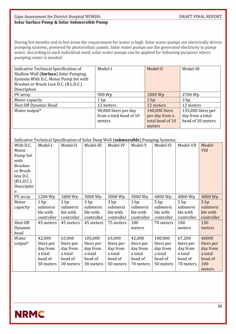
Gaps Assessment for District Hospital WOKHA DRAFT FINAL REPORT
30
Solar Surface Pump & Solar Submersible Pump
During hot months and in hot areas the requirement for water is high. Solar water pumps are electrically driven pumping systems, powered by photovoltaic panels. Solar water pumps use the generated electricity to pump water. According to each individual need, solar water pumps can be applied for following purposes where pumping water is needed:
Indicative Technical Specification of Shallow Well (Surface) Solar Pumping Systems With D.C. Motor Pump Set with Brushes or Brush Less D.C. (B.L.D.C.) Description
Model-I Model-II Model-III
PV array 900 Wp 1800 Wp 2700 Wp Motor capacity 1 hp 2 hp 3 hp Shut Off Dynamic Head 12 meters 12 meters 12 meters Water output* 90,000 liters per day
from a total head of 10 meters
140,000 liters per day from a total head of 10 meters
135,000 liters per day from a total head of 20 meters
Indicative Technical Specification of Solar Deep Well (submersible) Pumping Systems: With D.C. Motor Pump Set with Brushes or Brush less D.C. (B.L.D.C.) Description
Model-I Model-II Model-III Model-IV Model-V Model-VI Model-VII Model-VIII
PV array 1200 Wp 1800 Wp 3000 Wp 3000 Wp 3000 Wp 4800 Wp 4800 Wp 4800 Wp Motor capacity
1 hp submersible with controller
2 hp submersible with controller
3 hp submersible with controller
3 hp submersible with controller
3 hp submersible with controller
5 hp submersible with controller
5 hp submersible with controller
5 hp submersible with controller
Shut Off Dynamic head
45 meters 45 meters 45 meters 75 meters 100 meters
70 meters 100 meters
150 meters
Water output*
42,000 liters per day from a total head of 30 meters
63,000 liters per day from a total head of 30 meters
105,000 liters per day from a total head of 30 meters
63,000 liters per day from a total head of 50 meters
42,000 liters per day from a total head of 70 meters
100,800 liters per day from a total head of 50 meters
67,200 liters per day from a total head of 70 meters
40000 liters per day from a total head of 100 meters

Gaps Assessment for District Hospital WOKHA DRAFT FINAL REPORT
31
5. CONCLUSIONS & RECOMMENDATIONS
There are few drawings and survey reports required for complete implementation.. Determine condition and adequacy of the wiring and grounding system. Determine ac voltage quality at the point of use Determine sources of power disturbances and their impacts of power disturbances on
equipment performance Analyse findings to identify immediate and long-term cost-effective solutions. Structure Design work for Solar Power Plant requires approval by Civil & Structural
Engineer. As per the annexure attached, CPWD DELHI Govt. rates, the calculation can be done only on
the basis of number of points, that can be calculated on the basis of single line diagram.
Please find the annexure attached with the document for the CPWD rates. In absence of any
diagram, and no detail of number of points, Just area wise costing is estimated for electrical
works.
WOKHA
Categories Recommendations
Generator Repair work for 125 Kva Kirloskar generators set.
Transformer 125KVA required
Inverter Batteries to be replaced. Battery back up less than 2 hours.
Portable Generator set Repair work needed
Solar water Heater Installation of Solar water heater Capacity of 500 Litres (FPC TYPE)
Area & Compound Lighting Energy Efficient Bulbs (LED) recommended minimum 10 numbers of Standalone Solar Street lighting advised.
Water Pump Surface Pump Submersible Pump
Solar Plant Capacity Solar Plant Capacity
1800Wp 4800Wp
Pump 5 HP
2 HP Pump
Maximum Total Head Maximum Total Head
15 Metres 150 Meters
Water Output @ 10 Meter Head Water Output @ 120 Meter Head
140000 Litres per day 40000 Litres per day
Surface Pump is advisable for running water, but solar surface pump is not a compulsion. When there is a Solar power Plant of 60 KWp for emergency needs. Then normal electric pump can be operated on grid supply and solar power can be used to run the pumps in emergency situations. Although considering the maintenance conditions of the district hospital, one standby and one running pump is advised for the hospital. Submersible Pump is recommended as per guidelines, although considering the terrain, and the depth of boring required in rocky soil for ground water. One existing submersible is enough to suffice the need considering the footfall in the district hospital.
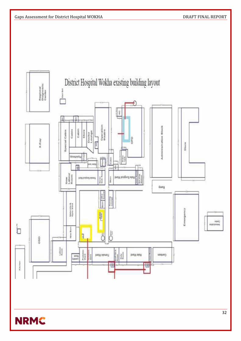
Gaps Assessment for District Hospital WOKHA DRAFT FINAL REPORT
32

Gaps Assessment for District Hospital WOKHA DRAFT FINAL REPORT
34
ANNEXURE I : LIST OF DOCUMENTS REFERRED
Glossary & Abbreviations [Containing Definitions, Expansion Of Abbreviations In Cerc/Sercs ] Benchmark cost for “Off Grid & Decentralized Solar PV application programme. MNRE order -
5/23/2009 – P&C (Pt.III) dated 3rd Nov 2014 Technical data specification sheet of Siemens Mobile X-ray machine with 2.5 kW HF generator for
general use, mobile single-tank, diagnostic X-ray system National Solar Mission MNRE. Annual Report (2016-17) MNRE Empanelled list of SPV suppliers and their respective specifications. MNRE Empanelled list of SWH suppliers and their respective specifications. MNRE Empanelled list of Solar Powered Pumps suppliers and their respective specifications. MNRE Empanelled list of Standalone Street Lights suppliers and their respective specifications. Emmvee Swh Brochure Emmvee SWH Quotation Emmvee SPV Brochures Emmvee SPV Quotation CPWD Wiring rates 2016 for Delhi Govt. Satec Envir Engineers specification for Control Panel Room & Mounting Structure.

Gaps Assessment for District Hospital WOKHA DRAFT FINAL REPORT
35
ANNEXURE II : LIST OF PEOPLE MET
Dr Robin Lotha
Dr Imkong Sanen

Gaps Assessment for District Hospital WOKHA DRAFT FINAL REPORT
36
ANNEXURE III : TERMS OF REFERENCE
Renewable Energy Expert
Base location: Kohima
Development of Questionnaires and Field Assessment Methodology
Site Visits and Data Collection
Technical Evaluation for Health Centres
Preparation of Detailed Project Report along with technical specifications, cost estimates for the sites.

Zunheboto District Hospital DPR
Gaps Assessment for District Hospital Zunheboto DRAFT FINAL REPORT
| 1
GAPS ASSESSMENT REPORT
NAGALAND
DISTRICT HOSPITALS

Gaps Assessment for District Hospital Zunheboto DRAFT FINAL REPORT
| 2
LIST OF ABBREVIATIONS
Abbreviations Full Name
CEA Central Electricity Authority
GRID Means High Voltage Backbone System Of Interconnecting Transmission Lines,
Substations And Generating Plants
DPR Detailed Project Report
DEVELOPER Entity Which Develops Project
AFC Annual Fixed Cost
CAPTIVE USER End User Of The Electricity Generated In A Captive Generating Plant
RENEWABLE ENERGY
SOURCES
Renewable Sources Such As Solar In This Case Including Its Integration With
Combined Cycle, Biomass, Bio Fuel Cogeneration, Urban/Municipal Waste And Other
Such Sources As Approved By The MNRE
SOLAR PV POWER The Solar Photo Voltaic (PV) Power Project That Uses Sunlight For Direct Conversion
Into Electricity Through Photo Voltaic Technology.
ETC Evacuated Tube Collector
FPC Flat Plate Collector
SPV Solar Photovoltaic
SPP Solar Photovoltaic Pump
AH Ampere Hour
KWH-DAY Kilo Watt Hour Per Day
KWH/M2 Kilo Watt Hour Radiation Per Square Meter Area
KVA Kilo Volt
KV Kilo Volt Ampere
KWH Kilo Watt Hour
MW Mega Watt
WP Watt Peak
LED Light Emitting Diode
APAC Asia-Pacific or Asia Pacific
CHC Community Health Centre
PHC Primary Health Centre

Gaps Assessment for District Hospital Zunheboto DRAFT FINAL REPORT
| 3
TABLE OF CONTENTS
List of Abbreviations ......................................................................................................................................................... 2
Table of Contents .............................................................................................................................................................. 3
Overview of North Eastern Electric Power Corporation Limited (NEEPCO) ................................................................. 4
Executed Projects ...................................................................................................................................................... 4
Projects under execution .......................................................................................................................................... 4
About the PROJECT ........................................................................................................................................................... 6
Nagaland Health Program ............................................................................................................................................. 6
Climate Demography & Population .................................................................................................................................. 6
Zunheboto ..................................................................................................................................................................... 6
Objectives of the assignment ............................................................................................................................................ 8
Methodology ..................................................................................................................................................................... 9
Process Flow.................................................................................................................................................................. 9
Checklist /Key Information Areas ............................................................................................................................... 10
IPHS GUIDELINES ......................................................................................................................................................... 11
Findings from Hospital Assessment ............................................................................................................................ 12
Current Status on Infrastructure and Gaps ............................................................................................................. 12
Equipment Load Distribution .................................................................................................................................. 16
As per Survey Standards & PMU Guidelines ........................................................................................................... 19
RECOMMENDATIONS...................................................................................................................................................... 22
Off Grid Solar Power Plant .......................................................................................................................................... 24
Servo Stabilizer ............................................................................................................................................................ 25
Electrical Works .......................................................................................................................................................... 25
Battery Inverter Sets ................................................................................................................................................... 27
Solar Water Heater ..................................................................................................................................................... 27
Solar Pump .................................................................................................................................................................. 28
Solar Street Lights ....................................................................................................................................................... 29
Energy Efficient Lighting (Led & T5) ............................................................................................................................ 29
Assumptions ...................................................................................................................... Error! Bookmark not defined.
COSTING & ESTIMATES ................................................................................................................................................... 33
Annexure I: List of documents referred .......................................................................................................................... 34
Annexure II: list of people met ....................................................................................................................................... 35
Annexure III: Terms of Reference ................................................................................................................................... 36

Gaps Assessment for District Hospital Zunheboto DRAFT FINAL REPORT
| 4
Overview of North Eastern Electric Power Corporation Limited (NEEPCO)
Executed Projects
(Total - 275 MW)
Kopili Hydro Electric Power Plant.
Comprises of three power stations (North Cachhar Hills District, Assam)
o Khandong power station (2x25 MW) – 50 MW
o Kopili power station (2x50 MW + 2x50 MW) – 200 MW
o Kopili power station, Stage-II (1x25 MW) – 25 MW
Ranganadi Hydro Electric Project – Arunachal Pradesh – biggest power plant – 405 MW
Doyang Hydro Electric Project – Nagaland – 75 MW
Assam Gas Based Power Plant – 291 MW – Combined cycle power station comprising 6 gas and 3 steam
turbines
Agartala Gas Turbine Plant – 84 MW – Open cycle with 4 gas turbines
Projects under execution
Kameng Hydro Electric Project – 600 MW – Run of the river scheme
Pare Hydro Electric Project – 110 MW – Run of the river scheme on river Dikrong
Tuirial Hydro Electric Project – Mizoram – 60 MW
Tripura Gas Based Power Project – 100 + 20 MW at Monachak, Tripura – scheduled for commissioning by
July, 2013(Delayed)
o Potential of hydroelectric power plant in Nagaland – 1574 MW
o Current Installed Capacity – 75 MW
Non Renewable Energy
"A non-renewable resource is a natural resource that cannot be re-made or re-grown at a scale comparable to its
consumption”.
Coal
Petroleum
Natural Gas Limited

Gaps Assessment for District Hospital Zunheboto DRAFT FINAL REPORT
| 5
"Renewable Energy is energy that is derived from natural processes that are replenished constantly. In its various forms,
it derives directly or indirectly from the sun.”
Of all seven sisters in North Eastern India, each state has their distinct features which differentiate them from each other.
Assam and Tripura, which is rich in petroleum resources, Arunachal Pradesh has a hydro power potential of 50000 MW
according to CEA. Meghalaya has coal and uranium resources, while Mizoram has rich Biomass, Sikkim and Nagaland
also have hydro potential. Nagaland has a huge potential to generate power from solar installations.
Anticipated demand of the state by the end of 2020 could be 500MW. To meet the requirement, the department has been
exploring ways and means to harness different sources of energy in the state, the report said. During the current financial
year (as on February 2011), 24MW Likimro Hydro Electric Project has generated 60.72 MU which has supplemented the
state’s power requirement as well as resources to a large extent.
1MW Lang Hydro Electric Project is scheduled to be completed in 2012 while 1 MW Tehok Hydro Electric Project is
scheduled to be completed by 2012-13.

Gaps Assessment for District Hospital Zunheboto DRAFT FINAL REPORT
| 6
ABOUT THE PROJECT
Nagaland Health Program ZUNHEBOTO (LAND OF WARRIORS) derived its name from two sets of words "Zunhebo" and "To" in Sumi dialect. Zunhebo is the name of a flowering shrub with white leaves which bear sponge like ears containing sweet juice and "To" means the top of a hill. Zunheboto District is situated in the heart of Nagaland and is bounded by Mokokchung district in the East and Wokha district in the West. Zunheboto is the home of the Sumis. Sumis are considered to be the Martial tribe among the Nagas. They have their colorful dance and songs. Their ceremonial war dresses are worth seeing. Tuluni is one of the most important festivals. It is observed in the second week of July every year. There are high hills spread over many areas of the district. The hills vary from 1000 to 2500 meters and most people live between1500 - 2000 meters altitude. The altitude of the district Hq. (ZBTO) is 1874.22 meters above sea level.
CLIMATE DEMOGRAPHY & POPULATION
Zunheboto According to the 2011 census, Zunheboto district has a population of 159,729, roughly equal to the nation of Saint Lucia.
This gives it a ranking of 598th in India (out of a total of 640). Zunheboto has a sex ratio of 981 females for every 1000
males, and a literacy rate of 86.26%.
The district had 210 villages and one statutory town, namely, Zunheboto Town and one Census Town namely, Satakha
Hq. The village having highest population Lazami under Pughoboto Circle at 2936 persons and the lowest population
under Aghunato Circle at 9 persons.
Zunheboto is the home to the Sumi Nagas, a warrior tribe of Nagaland. Head hunting was practiced extensively until the
advent of the Christian missionaries who converted the warriors to Christianity. Today the people are peaceful and
hardworking, practicing agriculture as their main occupation. The district is also home to the largest Baptist church in
Asia, the Sumi Baptist Church.
Soil: Almost all the soils of the Zunheboto district belong to the following classes/orders. There are alluvial soil, Forest
soil (organic) pertaining to moolisol, non-laterised soil and soils of high altitudes belonging to order spodosals.
Rivers: There are three important rivers in the district, viz, Tizu river originating in Tuensang district flows down
towards south crossing at the centre of Zunheboto district and join Chindwin. Doyang river originating in Japfu passes
through west part of the district and joins Dhansiri in Assam. Tsutha river, originating in North East of Zunheboto drains
eastern part of the district and joins Tizu below Nihoshe village, where a Mini Hydel Power project is located. Most of the
area under terrace cultivation on Tizu, Tsutha and Mela a tributary of Tizu river
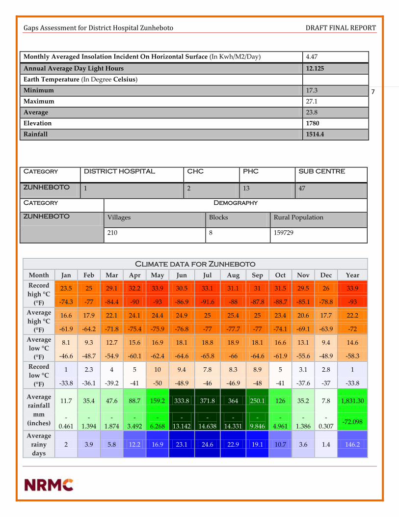
Gaps Assessment for District Hospital Zunheboto DRAFT FINAL REPORT
| 7
Monthly Averaged Insolation Incident On Horizontal Surface (In Kwh/M2/Day) 4.47
Annual Average Day Light Hours 12.125
Earth Temperature (In Degree Celsius))
Minimum 17.3
Maximum 27.1
Average 23.8
Elevation 1780
Rainfall 1514.4
Category DISTRICT HOSPITAL CHC PHC SUB CENTRE
ZUNHEBOTO 1 2 13 47
Category Demography
ZUNHEBOTO Villages Blocks Rural Population
210 8 159729
Climate data for Zunheboto
Month Jan Feb Mar Apr May Jun Jul Aug Sep Oct Nov Dec Year
Record
high °C
(°F)
23.5 25 29.1 32.2 33.9 30.5 33.1 31.1 31 31.5 29.5 26 33.9
-74.3 -77 -84.4 -90 -93 -86.9 -91.6 -88 -87.8 -88.7 -85.1 -78.8 -93
Average
high °C
(°F)
16.6 17.9 22.1 24.1 24.4 24.9 25 25.4 25 23.4 20.6 17.7 22.2
-61.9 -64.2 -71.8 -75.4 -75.9 -76.8 -77 -77.7 -77 -74.1 -69.1 -63.9 -72
Average
low °C
(°F)
8.1 9.3 12.7 15.6 16.9 18.1 18.8 18.9 18.1 16.6 13.1 9.4 14.6
-46.6 -48.7 -54.9 -60.1 -62.4 -64.6 -65.8 -66 -64.6 -61.9 -55.6 -48.9 -58.3
Record
low °C
(°F)
1 2.3 4 5 10 9.4 7.8 8.3 8.9 5 3.1 2.8 1
-33.8 -36.1 -39.2 -41 -50 -48.9 -46 -46.9 -48 -41 -37.6 -37 -33.8
Average
rainfall
mm
(inches)
11.7 35.4 47.6 88.7 159.2 333.8 371.8 364 250.1 126 35.2 7.8 1,831.30
-
0.461
-
1.394
-
1.874
-
3.492
-
6.268
-
13.142
-
14.638
-
14.331
-
9.846
-
4.961
-
1.386
-
0.307 -72.098
Average
rainy
days
2 3.9 5.8 12.2 16.9 23.1 24.6 22.9 19.1 10.7 3.6 1.4 146.2

Gaps Assessment for District Hospital Zunheboto DRAFT FINAL REPORT
| 8
AVG VILLAGE PER CENTRE
CHC 105
PHC 16
SC 4
AVG POPULATION
CHC 69000
PHC 11000
SC 3000
OBJECTIVES OF THE ASSIGNMENT
The objective of the study is to support the Nagaland health department, in accessing the needs, defining technical
requirements and planning investments to provide appropriate technology for health facilities of different districts.
Strategies for improving working conditions in public hospitals
24 hours power supply in district hospital of Zunheboto, Nagaland
Access to a strong utility grid, they have had to rely on engine- or turbine-driven generator sets that, while highly
reliable, typically produce power at a much higher cost than a large utility.
Now a better model is emerging that combines newly cost-effective renewable energy from wind or solar sources
with conventional diesel- or gas-fueled generation. These installations, called hybrid micro grids, also employ
energy storage to add power system stability and enable further energy cost reduction. Aided by sharp declines
in the cost of wind and solar energy, as well as lower energy storage costs relative to the price of fuel, hybrid
micro grids are well suited to a host of applications, including individual buildings, resorts, mine sites, remote
villages, small islands and others.
Keeping the systems healthy in a district hospital is an essential part for well-being of the entire state. However, it can be
challenging to stay up-to-date with the requirements and developments of hospital mechanical and electrical systems.
There are many low-cost things we can do from a design standpoint that can reduce energy use. Electrical systems control
nearly every aspect of a modern hospital. A hospital’s electrical system must provide reliable, disturbance-free power
around the clock. Furthermore, it must be exceedingly safe, because patients are often in vulnerable states. All of this
must be accomplished according to overlapping regulations from national and local authorities.
District Health Centre (low energy requirements)
o Lighting the facility.
o Maintaining the cold chain for vaccines, blood, and other medical supplies – one or two refrigerators may be
used.
o Utilizing basic lab equipment – a centrifuge, microscope, incubator, suction machine, oxygen concentrator, ECG
machine, Cardiac monitor, Ultrasound and hand-powered aspirator.
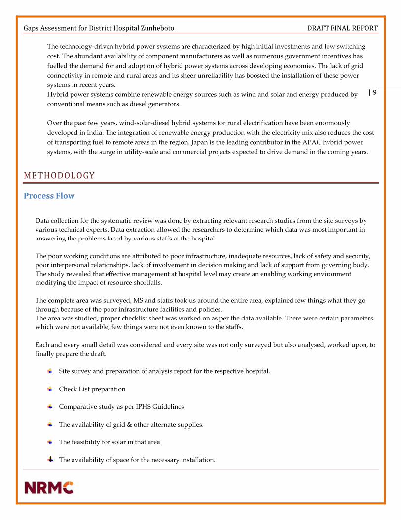
Gaps Assessment for District Hospital Zunheboto DRAFT FINAL REPORT
| 9
The technology-driven hybrid power systems are characterized by high initial investments and low switching
cost. The abundant availability of component manufacturers as well as numerous government incentives has
fuelled the demand for and adoption of hybrid power systems across developing economies. The lack of grid
connectivity in remote and rural areas and its sheer unreliability has boosted the installation of these power
systems in recent years.
Hybrid power systems combine renewable energy sources such as wind and solar and energy produced by
conventional means such as diesel generators.
Over the past few years, wind-solar-diesel hybrid systems for rural electrification have been enormously
developed in India. The integration of renewable energy production with the electricity mix also reduces the cost
of transporting fuel to remote areas in the region. Japan is the leading contributor in the APAC hybrid power
systems, with the surge in utility-scale and commercial projects expected to drive demand in the coming years.
METHODOLOGY
Process Flow
Data collection for the systematic review was done by extracting relevant research studies from the site surveys by
various technical experts. Data extraction allowed the researchers to determine which data was most important in
answering the problems faced by various staffs at the hospital.
The poor working conditions are attributed to poor infrastructure, inadequate resources, lack of safety and security,
poor interpersonal relationships, lack of involvement in decision making and lack of support from governing body.
The study revealed that effective management at hospital level may create an enabling working environment
modifying the impact of resource shortfalls.
The complete area was surveyed, MS and staffs took us around the entire area, explained few things what they go
through because of the poor infrastructure facilities and policies.
The area was studied; proper checklist sheet was worked on as per the data available. There were certain parameters
which were not available, few things were not even known to the staffs.
Each and every small detail was considered and every site was not only surveyed but also analysed, worked upon, to
finally prepare the draft.
Site survey and preparation of analysis report for the respective hospital.
Check List preparation
Comparative study as per IPHS Guidelines
The availability of grid & other alternate supplies.
The feasibility for solar in that area
The availability of space for the necessary installation.

Gaps Assessment for District Hospital Zunheboto DRAFT FINAL REPORT
| 10
Checklist /Key Information Areas
Location (District, State) ZUNHEBOTO
Latitude 26.009N
Longitude 94.523E
Age of Building New (5 yrs.) & Old (50 yrs.)
Load bearing capacity of terrace YES
Area identified for Installation of the solar power plant Children ward
OPD Building
OT Complex
Nursing Hostel
Roof Type Purlin/ Asbestos/ RCC
Super Structure for Mounting Ample roof top space available.
If we still plan for super structures.(It
needs to be discussed with civil engineer
as location is in seismic zone )
No. of Floor to terrace G+2
Soil Type Rocky
Transformer Make & Rating if available 100 KVA
Transformer Age New
DG availability 25 KVA (Running)
DG manufacturer & Rating Mahindra Powerol Generator sets
DG age New
Current Power Scenario 10 Hours
Electricity Tariff Not available
Proposed Storage Area for Inverter and Batteries OPD Building / OT Complex
Risk of flooding during monsoons No
Land clearing requirements IF any Yes for Ground mounting
Transportation Issues & dependencies Costing High

Gaps Assessment for District Hospital Zunheboto DRAFT FINAL REPORT
| 11
IPHS GUIDELINES
Hospital Building – Planning and Lay out
Appearance and upkeep There shall be provision of adequate light in the night so hospital is visible from approach road. Signage The building should have a prominent board displaying the name of the Centre in the local language at the gate and on the building. Signage indicating access to various facilities at strategic points in the Hospital for guidance of the public should be provided. Florescent Fire Exit plan shall be displayed at each floor. Roads shall be illuminated in the nights Environmental friendly features The Hospital should be, as far as possible, environment friendly and energy efficient. Rain-Water harvesting, solar energy use and use of energy-efficient bulbs/ equipment should be encouraged. Provision should be made for horticulture services including herbal garden. Intensive Care Unit and High Dependency Wards General - Location This unit should be located close to operation theatre department and other essential departments, such as, X-ray and pathology so that the staff and ancillaries could be shared. This unit will also need all the specialized services, such as, piped suction and medical gases, uninterrupted electric supply, heating, ventilation, central air conditioning and efficient life services. A good natural light and pleasant environment would also be of great help to the patients and staff as well. Emergency Unit Emergency block should have ECG, Cardiac Monitor with Defibrillator, Multi parameter Monitor, and Ventilator. Operation Theatre This unit also needs constant specialized services, such as piped suction and medical gases, electric supply, heating, air-conditioning, ventilation and efficient lift service, if the theatres are located on upper floors. III) Central Sterile and Supply Department (CSSD) As the operation theatre department is the major consumer of this service, it is recommended to locate the department at a position of easy access to operation theatre department. It should have a provision of hot water supply. Hospital Laundry It should be provided with necessary facilities for drying, pressing and storage of soiled and cleaned linens. It may be outsourced. Mortuary Proper illumination and air conditioning shall be provided in the post mortem room. A separate room for body storage shall be provided with at least 2 deep freezers for preserving the body. Electric Engineering Sub Station and Generation Electrical load requirement per bed = 3 KW Electric substation and standby generator room should be provided. Illumination The illumination and lightning in the hospital should be done as per the prescribed standards. Emergency Lighting Shadow less light in operation theatre and delivery rooms should be provided. Emergency portable light units should be provided in the wards and departments. Ventilation The ventilation in the hospital may be achieved by either natural supply or by mechanical exhaust of air. Air-conditioning and Room Heating in operation theatre and neo-natal units should be provided. Air coolers or hot air convectors may be provided for the comfort of patients and staff depending on the local needs. Hospital should be provided with water coolers and refrigerator in wards and departments depending upon the local needs.

Gaps Assessment for District Hospital Zunheboto DRAFT FINAL REPORT
| 12
Findings from Hospital Assessment
Current Status on Infrastructure and Gaps
From this survey, it is clear that provision of a positive working environment is crucial for the wellbeing of the
employees, the patients as well as the organisation. Provision of adequate infrastructure is of high importance.
Mechanical and electrical systems act as vital organs to a hospital, providing power, water, fresh air and other
important elements that keep the hospital running efficiently and safely.
Please find the infrastructure requirements of a district hospital and also do go through the Findings at the site.
They cannot run the lab equipment or the x-ray without starting the generator. Whenever there is cloud cover the
power cuts happen. Power disruptions result in a disruption of treatment programs or the inability to reliably use
electrical appliances such as laboratory equipment.
Categories Findings
Grid Power Hospital has 100 KVA transformer
Power Availability Power Availability – 10 hours (Average)
(Weather Issues) (At times no power for days)
Generator 25 Kva available
Inverter Inverter Battery Set – 2 Sets available
Portable Generator set Portable Generator set – 1 Set
Solar water Heater No water heater
Wiring condition Old wiring requires repair
Water Pump No Bore well
Rain water harvesting available
Running water available.
Area & Compound Lighting Very less outdoor illumination
Patients Footfall Count (Monthly Average) Patients in OPD 600
Patients in IPD 50
Cases of normal deliveries 30
Cases for C-Section deliveries 15
Other minor & major cases 35
Hospital Status Provision for Beds 75
Currently available 64
Plans for up gradation 100
Occupied currently 8
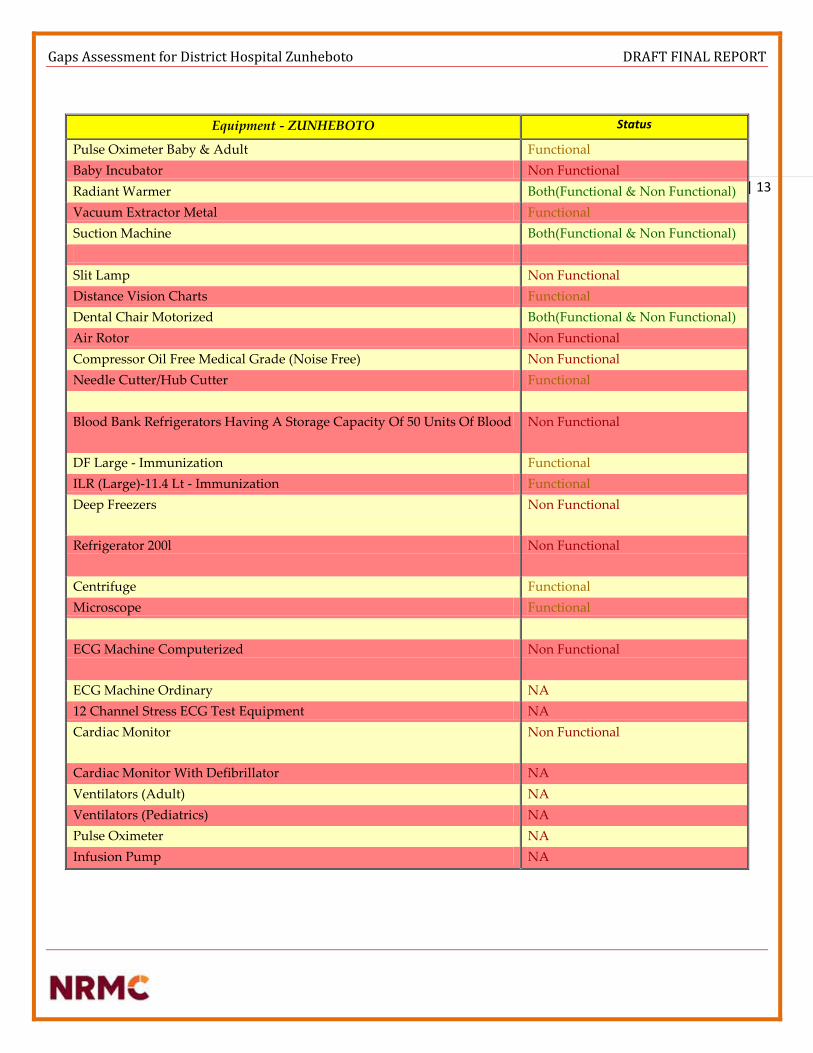
Gaps Assessment for District Hospital Zunheboto DRAFT FINAL REPORT
| 13
Equipment - ZUNHEBOTO Status
Pulse Oximeter Baby & Adult Functional
Baby Incubator Non Functional
Radiant Warmer Both(Functional & Non Functional)
Vacuum Extractor Metal Functional
Suction Machine Both(Functional & Non Functional)
Slit Lamp Non Functional
Distance Vision Charts Functional
Dental Chair Motorized Both(Functional & Non Functional)
Air Rotor Non Functional
Compressor Oil Free Medical Grade (Noise Free) Non Functional
Needle Cutter/Hub Cutter Functional
Blood Bank Refrigerators Having A Storage Capacity Of 50 Units Of Blood Non Functional
DF Large - Immunization Functional
ILR (Large)-11.4 Lt - Immunization Functional
Deep Freezers Non Functional
Refrigerator 200l Non Functional
Centrifuge Functional
Microscope Functional
ECG Machine Computerized Non Functional
ECG Machine Ordinary NA
12 Channel Stress ECG Test Equipment NA
Cardiac Monitor Non Functional
Cardiac Monitor With Defibrillator NA
Ventilators (Adult) NA
Ventilators (Pediatrics) NA
Pulse Oximeter NA
Infusion Pump NA

Gaps Assessment for District Hospital Zunheboto DRAFT FINAL REPORT
| 14
Although the survey and analysis shows that Nagaland public health infrastructure is yet to reach the
desired facilities as per Indian Public Health Standards as much as that: Only in Zunheboto district
average sub centers cover desired population of 3,000 per Sub center and 11000 for PHC compared to in
rest of all the districts average of each sub center covers population more than 4,000 to as high as 16,000
for PHCs.
Base Load Distribution
0 500 1000 1500 2000 2500 3000 3500 4000 4500 5000
RFD BUILDING
OT COMPLEX
X-RAY ROOM
OPD BUILDING
NURSING HOSTEL
MS & CMO BUILDING
Emergency
Ward
nursing superidendent
female medical ward
maternity ward
nurse duty room
labor room
children ward
blood bank
female surgical ward
nurse office
surgical ward duty room
male surgical ward
nurses room
MS ROOM
ADMIN ROOM
CONFERENCE ROOM
STORE
EYE OPD
AYUSH
IMMUNISATION
MAJOR O.T ROOM
MINOR OT ROOM
MTP ROOM
DOCTOR ROOM
15 TOILETS
CORRIDORS
LIGHTING LOAD DISTRIBUTION

Gaps Assessment for District Hospital Zunheboto DRAFT FINAL REPORT
| 15
Total Emergency Lighting Load 20300
Load Utilization Factor 8120
Total Consumption 48720
Units Consumption 48.72
Required Generation 11.07
EQUIPMENT No of STANDARD AS
PER IPHS
TOTAL WATTAGE OPERATIING
FREQUENCY
Equipment (in Watt) (in Watt)
Total Emergency
Lighting Load
8120 6 Hours
Projector
Xerox machine
1 500 500
Mobile Charger 3 5 15
Computer
Laptop 9 cell with
Modem with UPS
Printer with Internet
connection
1 800 800
TOTAL ADMIN LOAD 1315 6 Hours
Pump (surface pump of 3
HP(2300+overload of
30%) As discussed with watsan
1 3000 3000
TOTAL SUPPORT LOAD 3000 2 Hours
TOTAL BASE LOAD 12435
Total Base Load – 12.435 KW
Total Base Load 12435
Total Consumption 62610
Units Consumption 62.61
Required Generation 14.22

Gaps Assessment for District Hospital Zunheboto DRAFT FINAL REPORT
| 16
Equipment Load Distribution
1%
4%
7%
11%
4%
1%
1%
25% 7% 2%
2%
4%
3%
3%
2%
2%
3%
0% 4%
1% 2%
1% 3% 4%
2%
1%
1%
CRITICAL LEVEL I
Pulse Oximeter Baby & Adult
Baby Incubator
Radiant Warmer
Suction Machine
Slit Lamp
Distance Vision Charts
Air Rotor
Compressor Oil Free Medical Grade(Noise Free)
Needle Cutter/Hub Cutter
Blood Bank Refrigerators Having AStorage Capacity Of 50 Units Of Blood
DF Large - Immunization
ILR (Large)-11.4 Lt - Immunization
Deep Freezers
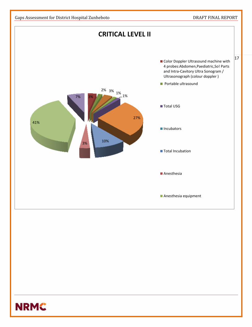
Gaps Assessment for District Hospital Zunheboto DRAFT FINAL REPORT
| 17
3%
2% 3% 1%
1%
27%
10% 3%
41%
7%
CRITICAL LEVEL II
Color Doppler Ultrasound machine with4 probes:Abdomen,Paediatric,So! Partsand Intra-Cavitory Ultra Sonogram /Ultrasonograph (colour doppler )
Portable ultrasound
Total USG
Incubators
Total Incubation
Anesthesia
Anesthesia equipment

Gaps Assessment for District Hospital Zunheboto DRAFT FINAL REPORT
| 18
(As per IPHS Guidelines) – If we go by IPHS Guidelines, it states very clearly that every bed in a
district hospital has a requirement of minimum 3 KW. As per thumb rule the basic power plant
requirement is mentioned below:-
Consumption & Generation
As per IPHS Guidelines
As per Number of available beds IN DH 79.2 kw
As per current provision of beds in DH 90 kw
Considering future expansions IN DH 120 kw
4%
0%
0% 0%
0%
1%
1%
1%
1%
1%
1% 2%
8%
15%
15%
2%
11%
7%
1%
5% 1%
0%
0%
6%
2%
0%
0%
9%
0% 1%
4%
CRITICAL LEVEL III
Computer +Printer+UPS+TV etc
Total OT
Total Critical Level-2
Critical Level-3
Labour & SNCU ward advancedequipment
Double sided blue light Phototheraphy
Pulse oxymeter baby & adult
infusion pump or syringe pump
cardiac monitor baby & adult
CFL phototherapy
Phototheraphy Unit
Cardio Toco Graphy Monitor

Gaps Assessment for District Hospital Zunheboto DRAFT FINAL REPORT
| 19
As per Survey Standards & PMU Guidelines
Equipment No of Standard as per IPHS Expected Solar usage Total Solar
Backup
Equipment (in Watt) (in hours) (in kWh)
Critical Level-1
Blood bank & Refrigeration
Deep freezers 1 300 6 1800
Refrigerator 200L 1 200 6 1200
Blood Bank refrigerators having a storage
capacity of 50 units of blood
1 460 6 2760
DF 200ltrs 1 150 6 900
ILR 180 liters 1 150 6 900
Total Blood Bank and Ref. 7560
OPD (only Emergency load)
Slit lamp 1 35 4 40
Distance vision Charts 1 100 4 104
Dental chair motorized 0 150 0
Air rotor 100
Compressor oil free medical grade (noise
free)
1200
Needle cutter/Hub cutter 500
Dental X ray IOP/OPG X ray viewer with
LED light
0 1500 0
Total OPD 144
Labour room (Normal delivery)
pulse Oximeter baby & adult 1 30 6 180
baby Incubator 1 400 6 2400
Radiant Warmer 1 750 6 4500
Vacuum extractor metal 0 2000 0 0
Suction Machine 1 320 6 1920
Total Labour Room 9000
Cardiopulmonary Equipment
ECG machine computerized 1 350 6 2100
ECG machine ordinary 1 40 6 240
12 channel stress ECG test equipment
treat mill
500 6 0
Echocardiography Machine 600 6 0
cardiac Monitor 600 6 0
Cardiac Monitor with defibrillator 1 100 6 600
Ventilators (Adult) 1 120 6 720
Ventilators (Pediatrics) 1 40 6 240
Pulse Oximeter 1 30 6 180
Pulse Oximeter with NIB.P* 1 15 6 90

Gaps Assessment for District Hospital Zunheboto DRAFT FINAL REPORT
| 20
Infusion pump 1 15 6 90
Total Cardiopulmonary Equipment 4260
Incineration
Incinerator and mortuary including waste
management
5000 0 0
Total Incineration
Total Critical Level-1 20964
Critical Level-2
Color Doppler Ultrasound machine with 4
probes:
500 2 1000
Portable ultrasound 0 250 0 0
Total USG 1000
Incubators
Incubator 1 500 4 2000
Total Incubation 2000
Anesthesia
Anesthesia equipment 1 200 4 800
Total Anesthesia 200 800
OT
Auto Clave HP Horizontal 0 4000 0 0
Operation Table Hydraulic Major 1500 4 0
Shadow less lamp ceiling type major* 1 500 4 2000
Sterilizer (Big instruments) 1 6000 4 24000
Computer + Printer + UPS + TV etc 1000 0
Total OT 26000
Total Critical Level-2 29800
Critical Level-3
Labour & SNCU ward advanced equipment
Double sided blue light Phototherapy 1 18 4 72
Pulse oxymeter baby & adult 30 0
infusion pump or syringe pump 80 0
cardiac monitor baby & adult 100 0
CFL phototherapy 150 0
Phototheraphy Unit 200 0
Cardio Toco Graphy Monitor 200 0
Nebulizer baby 200 0
Newborn care Equipment 250 0
Suction Machine 320 0
Infantometer 500 0
Servo- controlled Radiant Warmer 2250 0
Total Labour & SNCU advanced equipment 72

Gaps Assessment for District Hospital Zunheboto DRAFT FINAL REPORT
| 21
Operation additional
Auto Clave HP Vertical (2 Bin) 1 4000 4 16000
Autoclave vertical single bin 0 4000 0 0
Shadow less lamp ceiling type minor* 1 500 4 2000
Sterilizer (small instrument) 1 3000 4 12000
Bowl Sterilizer Medium 0 2000 0 0
Diathermy Machine (Electric Cautery) 1 250 4 1000
Suction Apparatus - electrical 1 1280 4 5120
Dehumidifier 350 0
Ultrasonic cutting and coagulation device 70 0
Total Operational Additional 36120
Laboratory
Electric microscope 1 30 4 120
Lab incubator 1500 0
Electric centrifuge,table top 3 1 500 4 2000
blood gas analyser 120 0
electrolyte analyser 1 60 4 240
Laboratory autoclaves 2500 0
automatic blood gas analyser-2 120 0
Blender 400 0
Hot air oven 1200 0
Total Laboratory 2360
ENT, Dental & Eye department, OPD Equipment
Dental X ray m/c 0 200 4 0
Dental Unit consisting of Dental Chair
and set of dental Equipment for
examination, extraction
1 1820 4 7280
Otoscope 20 0
Slit Lamp 1 30 0
Head Light 300 0
Total - ENT, Dental & Eye department,
OPD Equipment
7280
Total Critical Level-3 45832
Critical level Load Pattern
A conservative approach has been taken and all the loads defined in the demand section may not be served. The
future demand may surpass the estimated supply which can later be catered by augmenting the plant size. A
detailed study and analysis of peak load, battery bank and grid analysis was done to serve additional loads over
and above the estimated supply.

Gaps Assessment for District Hospital Zunheboto DRAFT FINAL REPORT
| 22
RECOMMENDATIONS
Categories
Recommendations
Power Availability
FLUCTUATING
Voltage
servo stabilizer recommended
Auxiliary power source
Hybrid Solar roof top power Plant advised
WIRING
REPLACEMENT of wiring in various sections
ELECTRICAL SWITCHGEARS DB BOX, METERS,PROTECTION DEVICES,MCB,
MAIN Panels
Generator
125 kva recommended
Inverter
4 sets recommended
Portable Generator set
Available
Solar water Heater
1 set – 500 liters advised
Water Pump
SOLAR SURFACE PUMP (3HP)
OUTDOOR Lighting
6 SET OF STREET LIGHTS
Corridor lighting & passages & staircases Energy Efficient Bulbs & t5 tube lights advised
Consumption & Generation
critical level I, II & III
Total WH Consumption 122596
Units Consumption 123

Gaps Assessment for District Hospital Zunheboto DRAFT FINAL REPORT
| 23
Total Base Load 12435
Total Base Load Consumption 62610
Units Consumption 62.61
Base load units consumption (0.8 load factor) 51
Total Critical Load Consumption 123
Critical load Units consumption (0.6 load factor) 74
Total Base load & Critical load consumption 186
Total consumption (Applied Load factor) 125
Total generation requirement 28.4 KwP
Losses in Solar generation due to various factors
Loss due to Irradiance variations 4.00%
PV loss due to temperature 8.50%
Array Soiling loss 2.00%
Module quality loss 1.00%
Module array mismatch loss 1.50%
Wiring Losses 0.50%
Total Solar Power required to be generated 28.4 KwP
Total Solar Power required after Correction Factor 33.78KwP
Autonomy as discussed with PMU 1 Day
Inverter Efficiency (Assumptions) 85 %
Battery Efficiency (Assumptions) 90%
BOS Efficiency (combiner boxes, wiring, main junction boxes) (Assumptions) 90%
Total Generation estimated from Solar Power Plant (After Losses) 44 KW
Estimated area Required for Installation 4500 Sq feet
Monthly Energy Consumption 4528 KWH
Yearly Energy Consumption 55000 KWH

Gaps Assessment for District Hospital Zunheboto DRAFT FINAL REPORT
| 24
Off Grid Solar Power Plant Off Grid Hybrid Solar Roof Top Power Plant of Capacity 37 KWP to 40 KWP is advised for ZUNHEBOTO district
hospital.
Area required for the installation of Power Plant will be 4000 sq feet.
As discussed there are various facilities (RCC roof tops) which can be used for integration of solar Power Plant
RCC ROOF TOP BUILDINGS SQ FEET
OT Complex (New Building) for Installation of 20 KwP Solar Roof Top Power Plant 2200
OPD Block (Old Building) for Installation of 20 KwP Solar Roof Top Power Plant 2100
Children Ward (Old Building) for Installation of 20 KwP Solar Roof Top Power Plant 2500
Nursing Hostel for Installation of 20 KwP Solar Roof Top Power Plant 2750
Total roof top area available for installation of SPV Power Plant 9550
Assumptions ( 80% Utilisation of total available space) 7640
New OT Complex, Children ward building can be utilised for control panel room

Gaps Assessment for District Hospital Zunheboto DRAFT FINAL REPORT
| 25
PV systems have been the focus of numerous efforts for rural electrification. The panels themselves typically have
a very long lifetime (20-30 years). Unfortunately, installation programs do not always include a sufficient service
component. Regular maintenance on batteries is essential while training local hospital staff in system
maintenance is essential for routine maintenance; a professional technician should also perform an annual
maintenance check, examining wiring connections, mounting bolts, and inverter operation.
PV systems typically have higher capital costs, but lower operating costs when compared to other energy
generation options. The availability of replacement components (model and brand) from local vendors should be
considered when procuring initial system components. End-user expectations of solar systems are often
unrealistic – education on the practical application of solar systems must accompany system design and
installation.
National standards for the placement, design, procurement, installation, and servicing of Photovoltaic systems
can help improve sustainability. Donor-funded PV systems often fail for lack of operating funds and local service
infrastructure. Detailed user manuals are critical – especially in cases where staff turnover is high. Local
ownership, often established through a contribution to initial system cost, is critical for system sustainability.
Servo Stabilizer The Servo Stabilizers uses an advanced electronic servo-motor concept to control a motorized variable transformer.
Because of the motorization, there is a small delay in voltage correction. However, output voltage accuracy is usually ±
1% with input voltage changes up to ± 50%. These machines are not affected unduly by power factor or frequency
variation. This type of technology tends to be extremely effective when considering large three phase applications, as it is
able to maintain its accuracy of all three phases, both line to line and line to neutral, irrespective of input voltage balance
and load balance at any power factor. They are also able to withstand large inrush currents, normally experienced with
inductive loads. However due to the mechanics of this type of stabilizer, periodic maintenance is required.
Various Design Topologies:-
o Single Phase Input & Single Phase Output
o Three Phase Input & Three Phase Output (Balanced Load)
o Three Phase Input & Three Phase Output (Unbalanced Load)
Electrical Works
Before recommending any change, a survey is advised which has to be conducted to identify distribution and grounding
problems, an initial physical site examination. It typically begins at the location of the sensitive electronic load equipment
and progresses back to the service entrance through the following sequence: sensitive load equipment, branch circuit
wiring, breaker panel, feeder wiring, main breaker panel, switchboard, and service entrance.
Start at the load equipment to check the wiring for code violations, adequate insulation, visible damage, miswired
connectors (e.g., phase and neutral-reversed or phase sequence reversed); secure connections; and measure the phase,
neutral, and ground voltages and currents.
Verify that the breakers in the panel feed the sensitive electronic load. Check that no other loads are on a dedicated circuit.
Visually check for any code violations, the use of wire nuts, insulation, other visible damage, and for secure connections.
Look for signs of burnt areas or carbonization, which indicate previous faults, flashovers, arcing, etc. Note the size of
incoming and outgoing conductors and make sure that they are adequately sized for the load, especially the neutral.

Gaps Assessment for District Hospital Zunheboto DRAFT FINAL REPORT
| 26
Check for shared neutrals and possible overloads with high harmonic loads. Check the temperature of the insulated face
of circuit breakers and for visual signs of overheating. Smell the panel, which may indicate overheating conditions.
Measure phase, neutral, and ground voltages and currents, as well as the voltage drop across each critical breaker. More
than about 0.1-V indicates a possibly bad unit. Look for signs of previous faults such as burnt areas, flashovers, arcing,
etc. Note the size of incoming and outgoing conductors. Check for visual signs of overheating. Use an infrared camera, if
available, for examining the hot spots in the main breaker panel and switchboard.
Digital Panel Meters
Feeder Protection
Feeder Protection Relays offering:-
o 1 phase, non-directional, Over Current or Earth Fault Relay
o 3 Phase Time delayed Over Current and Earth fault + Instantaneous
o Over Current and Earth Fault
Final Distribution Products (MCCB, RCCB, RCBO, DBs):-
Complete final distribution portfolio for building segment
MCB conforms to IS/IEC 60898 with breaking capacity of 6kA throughout the range
RCCB conforms to IS 12640-1, IEC 61008 and available from 25A to 63A with 30mA and 100mA sensitivity.
EL+MCBs offer 3 in 1 protection against earth leakage overload and short circuit
Isolator available in DP, TP and FP from 40A to 100A
Ergonomically designed complete range of distribution boards
All protection devices (MCB, RCCB, EL+MCB) have ISI mark ensuring complete assurance
Cable Ducts
Cable ducts are manufactured from specially compounded high impact rigid polyvinyl chloride. These will not peel, chip
or crack. It resists oil, salt solution and fungus.
It is non-flammable confirming to UL 94 V0 standards, warp-proof and non-brittle. It has high dielectric strength and
withstands temperature up to 60C.
LED Indicators, Push Button Actuators & Stations
Remote control units play a crucial role on factory shop floor for operational safety and reliability. Reliable push buttons
and indicators from our partners ESBEE have been trusted by users across industries over the past four decades.
Illuminated actuators with LED have snap fit for ease in assembly with low power consumption of 0.6 W max. Push
button stations provide round ergonomic enclosure with good aesthetics that occupies less space. They are robust, easy to
grip, assemble and operate. It is available in standard configuration of actuators and LED indicators.

Gaps Assessment for District Hospital Zunheboto DRAFT FINAL REPORT
| 27
Battery Inverter Sets A tubular battery uses technology that seals the active material in polyester tubes called gauntlets, instead of pasting it on
the surface of the plate. As a result, there's no shedding or corrosion, ensuring long battery life. Owing to their toughness
and durability, tubular batteries can operate at extreme temperatures, and are used in high cyclic applications involving
frequent and prolonged power outages.
A typical power inverter device or circuit requires a relatively stable DC power source capable of supplying enough current for the intended power demands of the system. The input voltage depends on the design and purpose of the inverter.
A power inverter device which produces a multiple step sinusoidal AC waveform is referred to as a sine wave inverter. To more clearly distinguish the inverters with outputs of much less distortion than the modified sine wave (three step) inverter designs, the manufacturers often use the phrase pure sine wave inverter. Almost all consumer grade inverters that are sold as a "pure sine wave inverter" do not produce a smooth sine wave output at all, just a less choppy output than the square wave (two step) and modified sine wave (three step) inverters. However, this is not critical for most electronics as they deal with the output quite well.
Where power inverter devices substitute for standard line power, a sine wave output is desirable because many electrical products are engineered to work best with a sine wave AC power source. The standard electric utility provides a sine wave, typically with minor imperfections but sometimes with significant distortion.
Sine wave inverters with more than three steps in the wave output are more complex and have significantly higher cost than a modified sine wave, with only three steps, or square wave (one step) types of the same power handling. Switch-mode power supply (SMPS) devices, such as personal computers or DVD players, function on quality modified sine wave power. AC motors directly operated on non-sinusoidal power may produce extra heat, may have different speed-torque characteristics, or may produce more audible noise than when running on sinusoidal power.
Solar Water Heater A 100 LPD Solar Water Heating (SWH) System having 2 square meter of collector area, can replace an electric geyser of 2 KW capacities for residential use and may save up to 1,500 units of electricity and up to 1.5 tons of CO2 per year depending upon the location of installation. The gross potential for solar water heating systems in India has been estimated to be about 140 million sq. m. of collector area. However, we have achieved about 12 million sq. meter collector area. There is a lot of potential for Solar Water Heating Systems in the country. Hot water usage in Hospitals
o Water for drinking o Water for housekeeping o Cooking water supply o Preheated water for the use of sterilizing equipment in autoclave machines. o Fulfillment of hot water required in new born care unit & labour rooms.
The main objective of the program is to promote the widespread use of solar water heaters in the country through a combination of financial and promotional incentives, and other support measures so as to conserve electricity and other fossil fuels, apart from peak load saving in cities and towns.

Gaps Assessment for District Hospital Zunheboto DRAFT FINAL REPORT
| 28
Heating water is very expensive as it requires a huge amount of energy. It is believed that 18% of domestic energy is used to heat water. In most homes and businesses this energy is generated from fossil fuels – gas and oil. Most modern domestic boilers will run on gas and heat water on demand. But many people still heat their water using electricity which is the most expensive way to heat water. Simple calculations on the energy output, savings on LPG and reduction of CO2 have been conducted. Preliminary results indicated that the saving on LPG based on proposed system was more than 20%. With a prospect of 100+ health facilities throughout the state, this project shall improve public awareness in energy conservation in the hot water production of their buildings and increase the market of the solar energy systems
o Solar thermal panels can only heat water and it requires space on roof top. o Annual maintenance is recommended.
Incorporating the Solar Hot Water System to the commercial hot water system heated by LPG boilers, there would
be a large potential in energy saving and greenhouse emission reduction.
Solar Pump A solar energy-powered water pump is a water pump running on the electricity that is generated by solar photovoltaic modules. Using solar energy as power source, such solar water pumps basically consist of three main components:
o Water pump
o Solar Photovoltaic modules
o Pump controller (and inverter)
Ground water exploration Most drinking water sources in Nagaland are surface water based, such as rivers, streams and ponds, and the systems are either gravity feed or pumping. Many habitations do not have viable surface water sources, and depletion of water sources is a common and distressing phenomenon. Augmentation of water supply in such habitations as well as providing new water supply facilities to non-covered habitations through ground water sources is an option which the department has started from 2013-14, by way of constructing deep tube wells. According to the water table level, distance to move the water and the pumping quantity requirements, different type sizes of water pumps apply. Shallow-well water pumping requirements are different from those for deep-well water pumping.
o Water is a precious resource. Wastage needs to be minimized
o It is important for hospitals to monitor its water usage
o Safe and adequate water is essential for effective hospital infection control and monitoring its
microbiological quality is of paramount importance
o Water for drinking
o Water for housekeeping
o Cooking water supply

Gaps Assessment for District Hospital Zunheboto DRAFT FINAL REPORT
| 29
o Water for Sterilization and cleaning of equipment and use in hospital laundry
Solar Surface Pump & Solar Submersible Pump
During hot months and in hot areas the requirement for water is high. Solar water pumps are electrically driven pumping systems, powered by photovoltaic panels. Solar water pumps use the generated electricity to pump water. According to each individual need, solar water pumps can be applied for following purposes where pumping water is needed.
Solar Street Lights
Solar street lights are independent of the utility grid resulting to lessened operation costs.
Solar street lights require lesser maintenance than conventional street lights. These have lower chances of
overheating. Since solar wires do not have external wires, the risk of accidents is minimized.
Solar street lights are environment-friendly because its panels are solely dependent to the sun hence eliminating your
carbon footprints contribution. Some parts of solar street lighting systems can be easily carried to remote areas making
these more efficient and handy solutions to lighting problems. Lighting up streets and roads enhance the comfort,
security and overall safety of our rapidly growing urban environments.
Standalone solar street lighting is designed to achieve better light uniformity and maximum spacing between poles for
both pedestrian and vehicle road applications, and higher efficiency to save panel size and battery capacity in solar
lighting system. With its die-cast aluminum housing, it is easy to maintain, has a long lifetime and a consistency you can
count on.
Energy Efficient Lighting (Led & T5)
“The most recent record for LED efficiency shows more than 300 lumen/watt. This result can be compared with regular
incandescent bulbs, and more than 15 incandescent bulbs will be required to create such luminance and close to 70 for

Gaps Assessment for District Hospital Zunheboto DRAFT FINAL REPORT
| 30
fluorescent lamps. LEDs last up to 100,000 hours, compared to 1,000 for incandescent bulbs and 10,000 hours for
fluorescent lights.”
A light-emitting diode, or LED for short, is a lamp that emits light in a very narrow band of wavelengths. Because of this,
LED’s are far more energy efficient than incandescent or fluorescent lights, which emit light in a much wider band of
wavelengths. LED’s produce light that renders a color similar (but not identical) to natural daylight, which is measured
on a scale called CRI, or Color Rendering Index. CRI’s range from 0-100, 100 being identical to natural daylight. Typical
LED’s are around 70-95 CRI, but it is not recommended to put anything indoors below 75 CRI. Like incandescent lamps
and unlike most fluorescent lamps, LEDs come to full brightness without need for a warm-up time.
o Average Requirement – 5000 lumens for an enclosed room
o Average Requirement – 3000 lumens for hallways, pathways, staircase, store, and kitchen.
On average, an incandescent bulb may last around 1000 hours, while a fluorescent (CFL) bulb producing the same
amount of light (in Lumens) may last around 8,000 hours, and an equivalent LED bulb may last around 25,000 hours.
Because of their efficiency, LED’s are generally more costly, but the energy saved on your electric bill pays off when
compared to incandescent bulbs.
When looking at a 60-Watt incandescent bulb, the price of running that single bulb for 20 years (based on 6 hours per day)
is $360. The price of running a 60-Watt LED equivalent for the same amount of time is only $72. So while an incandescent
might only be around $1.00/bulb in comparison to $10.00/bulb for the LED, think about how much you would save by
replacing every bulb in your house!
The 20-year savings on replacing a single candescent bulb with an LED would be $288

Gaps Assessment for District Hospital Zunheboto DRAFT FINAL REPORT
| 31
GALLERY

Gaps Assessment for District Hospital Zunheboto DRAFT FINAL REPORT
| 32
CONCLUSION
o Led Solar Standalone Street Light is planned to be installed in and around the campus for outdoor
lighting.
o Solar Power Plant of 40 KwP capacity will be integrated on roof top space available in the hospital. The
RCC roof top will be used for the installation of Hybrid solar power plant along with control panel
room which can be placed either in OT Complex or in other premises as per availability.
o Solar Water Heater (FPC / ETC) of 1000 Litres capacity to be installed on the roof top, total area
occupied by the water heater will be roughly 100 sq feet. There are different types of water heating
systems available, depending upon the water quality; we have finalized to install Evacuated Tube
Collector system, to avoid clogging of Cu Tubes which will frequently happen in Flat Plate Collector
System.
o There are two Inverter battery set which is currently available in the hospital, but both of them do
provide a back-up of not even 30 minutes. So we have concluded to repair or replace existing battery-
inverter system and there is a plan to install two more inverter battery set, one for operation theatre
and another for Labour room.
o There is a plan to replace existing incandescent bulbs by Led bulbs and led tubes or panel lights, so that
we can reduce the basic lighting load.
o The hospital does have their own transformer of 100 KVA, but the major issue is that there are power
failure maximum times because of the power scarcity and also due to weather conditions in the hilly
region. When also there is the electricity, the voltage fluctuation is quite common so the servo stabilizer
is decided of 100 KVA capacity, the inputs of all the major equipment in hospitals can be connected
through servo stabilizer to prevent the equipment from damaging during high voltage and high surge
currents.
Assumptions:
There are few drawings and survey reports required before going into implementation. Kindly consult before
implementation.
o Single Line Diagram of the entire hospital
o Determine condition and adequacy of the wiring and grounding system.
o Structure Design work for Solar Power Plant requires approval by Civil & Structural Engineer.
o Solar Pump (A.C or D.C) has been mentioned under water & sanitation report.
NOTE**In absence of electrical single line diagram and in absence of any details to calculate the costing of the
electrical works in the facility. The costing has been done on the basis of assumptions, of rate per square feet area.
The rates have been discussed with the building contractors working in the North-eastern region and cost
estimate has been prepared. The cost estimate per square feet includes products from only these mentioned
companies [Polycab, Havells, KEI, L&T, C&S] **
As per the annexure attached, CPWD DELHI Govt. rates, the calculation can be done only on the basis of number
of points, that can be calculated on the basis of single line diagram. Please find the annexure attached with the
document for the CPWD rates. In absence of any diagram and no detail of number of points, Just area wise
costing is estimated for electrical works.

Gaps Assessment for District Hospital Zunheboto DRAFT FINAL REPORT
| 34
ANNEXURE I: LIST OF DOCUMENTS REFERRED
o Glossary & Abbreviations [Containing Definitions, Expansion Of Abbreviations In Cerc/Sercs ]
o Benchmark cost for “Off Grid & Decentralized Solar PV application programme. MNRE order -5/23/2009 – P&C
(Pt.III) dated 3rd Nov 2014
o Technical data specification sheet of Siemens Mobile X-ray machine with 2.5 kW HF generator for general use,
mobile single-tank, diagnostic X-ray system
o National Solar Mission MNRE. Annual Report (2016-17)
o MNRE Empanelled list of SPV suppliers and their respective specifications.
o MNRE Empanelled list of SWH suppliers and their respective specifications.
o MNRE Empanelled list of Solar Powered Pumps suppliers and their respective specifications.
o MNRE Empanelled list of Standalone Street Lights suppliers and their respective specifications.
o Emmvee Swh Brochure
o Emmvee SWH Quotation
o Emmvee SPV Brochures
o Emmvee SPV Quotation
o CPWD Wiring rates 2016 for Delhi Govt.

Gaps Assessment for District Hospital Zunheboto DRAFT FINAL REPORT
| 35
ANNEXURE II: LIST OF PEOPLE MET
o Dr Khesto Zhimo (MS)
o Dr Mughalu
o Ms Kughani ( Blood bank)
o Ms Shetoli

Gaps Assessment for District Hospital Zunheboto DRAFT FINAL REPORT
| 36
ANNEXURE III: TERMS OF REFERENCE
Renewable Energy Expert - Base location: Kohima
o Development of Questionnaires and Field Assessment Methodology
o Site Visits and Data Collection
o Technical Evaluation for Health Centres
o Preparation of Detailed Project Report along with technical specifications, cost estimates.


![[XLS]nhmnagaland.innhmnagaland.in/programmes_file_path/HR- Incumbency Sept... · Web viewZupeno Ezung Kekhriesenuo Kintso Medongunuo Rokovonuo Chadi Shürhosienuo Belho Kedovikhonuo](https://img.pdfslide.net/doc/110x75/5aaf53347f8b9a5d0a8d4aea/xls-incumbency-septweb-viewzupeno-ezung-kekhriesenuo-kintso-medongunuo-rokovonuo.jpg)


![[XLS]nhmnagaland.innhmnagaland.in/programmes_file_path/HR- Incumbency .xlsx · Web viewZupeno Ezung Kekhriesenuo Kintso Medongunuo Rokovonuo Chadi Shürhosienuo Belho Kedovikhonuo](https://img.pdfslide.net/doc/110x75/5aaf53347f8b9a5d0a8d4aee/xls-incumbency-xlsxweb-viewzupeno-ezung-kekhriesenuo-kintso-medongunuo-rokovonuo.jpg)