Embed Size (px)
Citation preview

ORNL/SPR-2019/1311
Assessment of Technology for Additive Manufacturing of Ceramic Nuclear Fuels
A. Nelson S. Getley D. Spalding September 2019

DOCUMENT AVAILABILITY
Reports produced after January 1, 1996, are generally available free via US Department of Energy (DOE) SciTech Connect.
Website http://www.osti.gov
Reports produced before January 1, 1996, may be purchased by members of the public from the following source:
National Technical Information Service 5285 Port Royal Road Springfield, VA 22161 Telephone 703-605-6000 (1-800-553-6847) TDD 703-487-4639 Fax 703-605-6900 E-mail [email protected] Website http://classic.ntis.gov
Reports are available to DOE employees, DOE contractors, Energy Technology Data Exchange representatives, and International Nuclear Information System representatives from the following source:
Office of Scientific and Technical Information PO Box 62 Oak Ridge, TN 37831 Telephone 865-576-8401 Fax 865-576-5728 E-mail [email protected] Website http://www.osti.gov/contact.html
This report was prepared as an account of work sponsored by an agency of the United States Government. Neither the United States Government nor any agency thereof, nor any of their employees, makes any warranty, express or implied, or assumes any legal liability or responsibility for the accuracy, completeness, or usefulness of any information, apparatus, product, or process disclosed, or represents that its use would not infringe privately owned rights. Reference herein to any specific commercial product, process, or service by trade name, trademark, manufacturer, or otherwise, does not necessarily constitute or imply its endorsement, recommendation, or favoring by the United States Government or any agency thereof. The views and opinions of authors expressed herein do not necessarily state or reflect those of the United States Government or any agency thereof.

ORNL/SPR-2019/1311
Transformation Challenge Reactor Program
Assessment of Technology for Additive Manufacturing of Ceramic Nuclear Fuels
A. Nelson S. Getley
D. Spalding
Date Published: September 2019
Milestone M3CT-19OR06090131
Prepared by OAK RIDGE NATIONAL LABORATORY
Oak Ridge, Tennessee 37831-6283 managed by
UT-BATTELLE, LLC for the
US DEPARTMENT OF ENERGY under contract DE-AC05-00OR22725

EXECUTIVE SUMMARY
The Transformation Challenge Reactor (TCR) program is assessing methods by which additive and advanced manufacturing (AM) may be used to drive a paradigm shift to deploy technologies for nuclear energy production. Nuclear fuel fabrication is currently performed using methods developed during the early days of nuclear energy development, relying on technologies dating back to the early twentieth century. Therefore, evaluating potential modern manufacturing methods for fuel fabrication is a key program objective. Many different types of materials and printing methods are used to produce three-dimensional parts that meet the description of additively manufactured parts. Most processes result in a near-net shape part, often with some finishing required to produce a workable product. Over the past decade, an unprecedented amount of investment has been spent on the development of AM, most of which has been directed towards metal and polymer applications. However, the nuclear fuel materials of interest to the TCR program are ceramic materials such as uranium dioxide and uranium mononitride. It should be recognized that the investment in ceramic additive has been limited compared to polymer and metal systems. This is owing to the smaller market size for ceramics compared to the markets for metals and polymers. This report analyzes and compares the different technologies available for use in ceramic additive processing, provides a detailed assessment of current manufactures and technologies, and concludes with a discussion of the systems with the most potential for use in fabrication of nuclear fuel materials.

iii
TABLE OF CONTENTS
Page
List of Figures ............................................................................................................................................... iv Acronyms ....................................................................................................................................................... v 1. Introduction: General Ceramic Manufacturing Discussion Relevant to Additive Manufacturing ....... 1 2. Overview of Ceramic Manufacturing Processes ................................................................................... 2 3. Overview of the Major Additive Manufacturing Technologies Available ........................................... 4
3.1 Photopolymerization Technologies ............................................................................................. 4 3.1.1 Lithoz (DLP) .................................................................................................................. 6 3.1.2 3DCERAM – Laser ........................................................................................................ 7 3.1.3 Prodways – Moving light DLP ....................................................................................... 7 3.1.4 Admatec – DLP .............................................................................................................. 8 3.1.5 Advantages and Disadvantages of Photopolymerization ............................................... 9
3.2 Binder Jet Technologies .............................................................................................................. 9 3.2.1 ExOne ........................................................................................................................... 10 3.2.2 voxeljet ......................................................................................................................... 10 3.2.3 3D Systems ................................................................................................................... 11
3.3 Material Extrusion Technologies ............................................................................................... 11 3.4 Powder Bed Fusion Technologies ............................................................................................. 11
3.4.1 HP ................................................................................................................................. 12 3.4.2 Osseomatrix .................................................................................................................. 12
3.5 Material Jetting Technologies ................................................................................................... 13 4. Assessment of Discussed AM technologies for Ceramic Fuel FAbrication ....................................... 14
4.1 Aluminum Oxide (Al2O3) .......................................................................................................... 15 4.2 Zirconium Oxide (ZrO2) ............................................................................................................ 15 4.3 Silicon Nitride (Si3N4) ............................................................................................................... 15 4.4 Silicon Carbide (SiC) ................................................................................................................. 16 4.5 Tricalcium Phosphate (TCP) ..................................................................................................... 16 4.6 Hydroxyapatite (HA or HAP) .................................................................................................... 16 4.7 Silica-Based Materials for Casting Cores .................................................................................. 16
5. Technology Limitations ...................................................................................................................... 17 5.1 Material Preparation for Additive Manufacturing ..................................................................... 17 5.2 Printing ...................................................................................................................................... 17 5.3 Post-printing .............................................................................................................................. 18
6. Conclusions and Recommendations for Future Assessments for Nuclear Fuel Fabrication .............. 19 7. References ........................................................................................................................................... 20

iv
LIST OF FIGURES
Page
Figure 1. Schematic representation of photopolymerization AM technology2 ............................................. 5 Figure 2. Differentiation in the two photopolymerization technologies2 ...................................................... 5 Figure 3. Lithoz DLP Technology Representation2 ...................................................................................... 6 Figure 4. Prodways addition of the moving gantry light source5 .................................................................. 8 Figure 5. Admatec’s ADMAFLEX Technology6 .......................................................................................... 8 Figure 6. Typical Binder Jet AM process7 .................................................................................................. 10

v
ACRONYMS
AM additive manufacturing CIM ceramic injection molding DLP digital light processing HAP hydroxyapatite MIM metal injection molding MJP multijet printer SLA stereolithography SLS selective laser sintering TCR Transformational Challenge Reactor

PAGE INTENTIONALLY LEFT BLANK

1
1. INTRODUCTION: GENERAL CERAMIC MANUFACTURING DISCUSSION RELEVANT
TO ADDITIVE MANUFACTURING
Modern ceramic engineering and manufacturing encompasses many areas, ranging from proper material selection and component design through complex industrial processing and marketing channels. Generally, nearly all ceramic products start with powders and are formed into an unfired (green) shape, and then they are fired (sintered) to densify and strengthen the microstructure before being finished and delivered to the end-use application. A small portion of the ceramic industry also uses solution-based precursors and pre-ceramic polymers to bypass the powder processing route. Since the term ceramic can convey everything from pottery to hip joints, depending on the audience, the overall market can be distilled into about five distinct, very different segments. The vast majority of the ceramic industry can be classified as (1) traditional ceramics, (2) technical ceramics, (3) biomedical ceramics, (4) glass/glass-ceramics, or (5) ceramic matrix composites; these categories are defined as follows:
• Traditional Ceramics – widespread and high-visibility consumer products like brick/tile,
whiteware such as tableware/sanitaryware, as well as industrially important products like refractories.
• Technical Ceramics – highly engineered materials offering superior mechanical, electrical,
thermal, biological, and chemical properties superior to plastics and metals, including a wide array of products integral and critical to many industrial and consumer products.
• Biomedical Ceramics – implantable devices, as well as bone grafting applications.
• Glass/Glass-Ceramic – lacking the defining regular crystal structure found in other ceramics; glass
materials are generally considered to be within the ceramic industry due to other similarities; includes unique glass compositions that have been engineered to more closely resemble ceramic properties of interest.
• Ceramic Matrix Composites – one or more discrete ceramic materials that have been reinforced
with fiber or particulate materials to increase the strength and toughness, and/or to reduce weight.
While commercial examples of additive manufacturing (AM) applications can be found in each of the five segments above, the focus and resources are currently being applied primarily to the technical and biomedical ceramic industries. These are the largest markets with applications and manufacturing processes that could more readily be impacted by the currently available AM technologies.
The Transformational Challenge Reactor (TCR) program has been established to fully assess the opportunity space for AM to surpass the material limitations that restrict development and deployment of nuclear power. The previous TCR milestone included the initial analysis of opportunities to use AM to significantly impact the nuclear fuel fabrication paradigm.1 The conventional limitations of three basic solid fuel types are examined, and possible fabrication technologies to overcome these limitations are outlined. While various avenues and possibilities were identified in the previous analysis, no specific AM processes were assessed. This document provides a detailed review of current commercial AM systems that are marketed as viable for ceramic materials.

2
2. OVERVIEW OF CERAMIC MANUFACTURING PROCESSES
In the overwhelming majority of manufacturing processes for ceramics, the composition and form of the starting raw material begins as a relatively fine powder. The final ceramic part properties are highly dependent on the characteristics of the starting powder in comparison to metals and plastics, which in most cases are melted and homogenized before being formed. Of critical importance to ceramic engineers tasked with delivering a product with demanding performance criteria are the powder particle size, shape, surface area, and purity. As ceramics are initially being formed, the particles must be packed to high density for proper sintering to occur. During the sintering process, the particles merge through liquid or solid-state diffusion mechanisms and form grains to remove the starting porosity and to develop the defining microstructure that determines the important properties. This process often results in dimensional shrinkages from 15–30%, which present challenges in the manufacturing process.
Many technical ceramics derive their important properties by using high surface area and submicron particles that more readily sinter to full density. As part of the proprietary processes of many ceramic manufacturers, raw material powders are sourced from suppliers and are then specially milled to a precise size and particle distribution, and they are also mixed with minor amounts of dopants and other compounds to affect certain properties of interest. Ball, jet, and attrition mills are used extensively in these processes. To enable forming of these very fine powders to shape, they must be specially processed through agglomeration or by forming slurries, pastes, or viscous masses. Agglomeration typically involves spray drying, in which a thin liquid slurry of the powder, along with organic binders, lubricants, and other additives, is converted into spherical agglomerates that range from about 30–200 µm. This agglomerated powder is free flowing to aid in the part forming process. This process is performed on a large volume for low cost. Pastes and viscous masses are created in a similar fashion by mixing the fine powders with similar additives with less amounts of liquid. Additives and binders are very important in modern ceramic manufacturing and encompass both organic and inorganic compounds that contribute specialized functions such as lubrication, rheology control, imparting green part strength for handling and machining operations, and sintering densification aids.
Forming methods for ceramics are varied and include casting (slip, gel, tape, freeze, cement), extrusion, pressing (dry, isostatic, hot), and injection molding. Casting involves creating a liquid-based slurry of the ceramic powder(s) and casting it into a mold of the part’s geometry. This method can create both solid and hollow-profile part shapes and is generally constrained by the ability to remove the part from the mold after casting. Advantages are the ability to produce large and complex shapes, while disadvantages lie in the slow speed of production. Extrusion is used extensively to make tubular or other long, constant-profile part geometries at high volume and low cost. Pressing is also used for high part volumes at low cost and for more simplified geometries. Dry, agglomerated powders containing appropriate binders and lubricants are fed to die cavities at high speed; the powder agglomerates are deformed and compacted between punches at high pressures and are quickly ejected from the die. Ceramic injection molding (CIM) technology basically evolved from plastic injection molding, in which geometrically complex parts can be produced at very high volumes. While it is challenging and expensive to develop, the process is unmatched in part quality and speed.
Once a part has been formed into a successful green shape, some manufacturing processes take advantage of this state to perform machining prior to the sintering. After this stage, similar operations are significantly more difficult and more costly to perform. Features such as holes and surface profiles that cannot easily be integrated into the forming stage can be added. An engineering challenge, especially for many technical ceramics, is to very accurately calculate the dimensional shrinkages that will occur during the sintering stage. This calculation is highly dependent on good control over the batch-to-batch powder and forming repeatability.

3
De-binding and sintering operations can occur in the same furnace/kiln or can be performed using separate equipment. The organic binders that were added to form the green part must be successfully removed without causing damage to the part. This must be done prior to reaching the sintering temperatures where gaseous byproduct escape can destroy the part. Typical organic binder levels can be as small as 1% for dry pressing and as high as 30% for some injection molding applications. Binder removal can encompass a simple thermal process, or it can involve a more complex chemical removal, depending on the forming process and binder level. Once a ceramic part has been sintered, it can be sold as fired, or it may require extensive finishing operations such as grinding, polishing, joining, or coating. To reduce costs, many traditional ceramics can be engineered and controlled during the manufacturing process to require minimal finishing operations. Allowable dimensional tolerances often range from 0.005 inches to 0.025 inches. Many technical ceramics require a high degree of form and fit and thus must be further finished, adding significant complexity and cost. Allowable dimensional tolerances can range from only 0.0001 inches up to 0.001 inches for many of these applications. High levels of in-process and final part quality control, including automation and inspection, have enabled technical ceramic manufacturers to reduce costs and become highly competitive, penetrating markets once dominated by nonceramic materials. Commercial nuclear fuel fabrication of uranium dioxide (UO2) typically incorporates minor grinding operations following sintering to apply the dish and chamfers used to mitigate pellet cladding mechanical interaction.

4
3. OVERVIEW OF THE MAJOR ADDITIVE MANUFACTURING TECHNOLOGIES AVAILABLE
There are currently five major types of AM technologies leading the emerging push into the ceramic industry. They are (1) stereolithography (photopolymerization), (2) binder jetting, (3) material extrusion, (4) powder bed fusion, and (5) material jetting. A summary table of the major companies and their respective technologies is shown in Table 1 below.
Table 1. Current leading companies and technologies in the ceramic AM industry.
AM Classification Company Technology Photopolymerization 3DCeram Fast Ceramics Production (FCP)
ADMATEC ADMAFLEX Prodways MOVINGLight
Lithoz Lithography-Based Ceramics Manufacturing (LCM) Binder jetting technologies
ExOne 3DP voxeljet Phenol Direct Binding (PDB)
3D Systems ColorJet Printing (CJP) Material extrusion technologies
WASP Liquid Deposition Modeling (LDM) 3D-figo Fused Feedstock Depositioning (FFD)
EnvisionTEC 3D Bioplotter nScrypt Micro Dispensing Nanoe Zetamix/Zetaprint
Powder bed fusion technologies
HP Multi Jet Fusion (MJF) OsseoMatrix Direct Laser Microfusion (DLM)
Material jetting technologies
XJet NanoParticle Jetting (NPJ)
3.1 PHOTOPOLYMERIZATION TECHNOLOGIES
In 1983, Charles W. Hull invented stereolithography (SLA), one of the first additive processes to be developed, and it continues to be a method to prototype parts and models. Stereolithography processes for ceramic AM use a slurry or paste of fine ceramic powder that has been dispersed in a photocurable monomer medium. The green part is built through selective polymerization using mask exposure and is currently the most widely used system for AM of technical ceramics. Either laser-based SLA or digital light projection (DLP) is used as the light source.
5
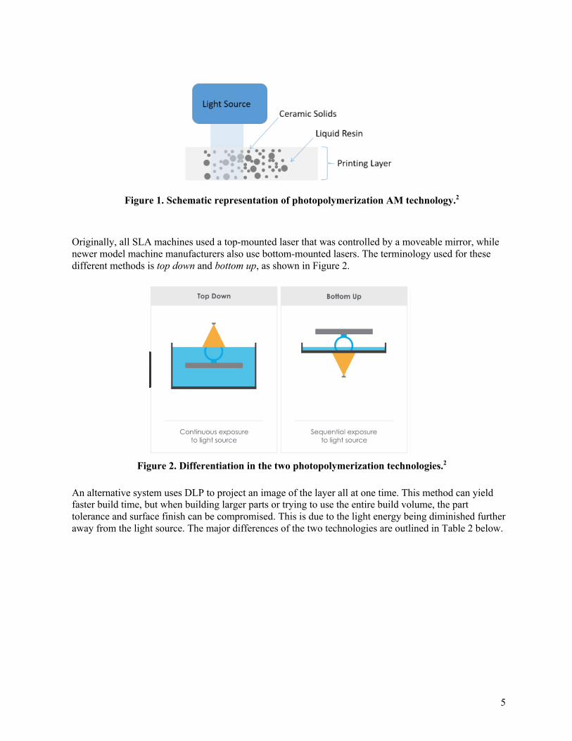
Originally, all SLA machines used a top-mounted laser that was controlled by a moveable mirror, while newer model machine manufacturers also use bottom-mounted lasers. The terminology used for these different methods is top down and bottom up, as shown in Figure 2.
An alternative system uses DLP to project an image of the layer all at one time. This method can yield faster build time, but when building larger parts or trying to use the entire build volume, the part tolerance and surface finish can be compromised. This is due to the light energy being diminished further away from the light source. The major differences of the two technologies are outlined in Table 2 below.
Figure 1. Schematic representation of photopolymerization AM technology.2
Figure 2. Differentiation in the two photopolymerization technologies.2

6
Table 2. Overview of top-down SLA and bottom-up DLP. Top-down SLA Bottom-up DLP
Projects UV from above the platform Projects layers as a flat image, hence not the same power reaches the entire part
The same power is provided all over the part on every layer Fast print time Can easily calculate Z compensation Feature resolution depends on the pixel size; therefore,
limitations exist for very fine part details Can take longer than DLP Projects layers as a flat image, hence not the same
power reaches all the part Capable of producing many parts on the same platform, bigger size
High viscosity paste, thin shearing behavior Several manufacturers offer more advanced machine and material technologies for ceramic AM utilizing photopolymerization. These manufacturers include Lithoz, Prodways, Admatec, and 3DCERAM. All of these manufacturers offer slightly different methods on the same core technology.
3.1.1 Lithoz (DLP)
The Lithoz DLP machine uses a transparent vat that is filled with a low-viscosity photocurable slurry. The vat rotates while a static wiper blade applies the slurry. The slurry is lit from below using a light-emitting diode projector and a mirror array in which pixels are operated individually, enabling dynamic mask exposure. The advantage of this procedure is that the entire surface area is exposed at the same time, making the duration of light exposure independent of the size of the cross section to be exposed. The basic principle of the Lithoz technique is illustrated in Figure 3.
Figure 3. Lithoz DLP Technology Representation.2
7
3.1.2 3DCERAM – Laser
The 3DCERAM uses a highly viscous paste loaded into a chamber with a piston at the bottom. The piston pushes up a small amount of the paste, and a re-coater spreads a thin layer onto the build platform. A high-speed UV laser scans the build platform, selectively solidifying the material. The process goes on layer after layer to create the green part, which is contained within a solid mass comprising cured and uncured resin. A unique consideration is that the 3D Ceram laser is designed to penetrate at least 3 layers in depth, therefore overlapping the polymerization from layer to layer to ensure a stronger green part. An advantage to this system is that the uncured paste in the build box acts as a support for the part, reducing the amount of supports required compared to other ceramic SLA systems. Complex geometries can be built and supported using their proprietary Freelink™ technology. An integral ceramic setter can even be incorporated as the part is being built with a single layer of unpolymerized material contained between the setter and the part. When firing the part and the setter together, they will shrink at the same rate, thus reducing the chance of part distortion. Also, the machines are open-source, and the build parameters can be adjusted to enable customers to develop their own materials using virgin photosensitive resin as the base material. A feature not presently available in other photopolymerization ceramic AM technologies on the market, the C900 series machines, can be fitted with a hybrid option which adds a 2-axis gantry system to the machine. This system uses a syringe to jet out a cavity in the part using high pressure air. The cavity can be filled with a sacrificial wax using the same gantry with different syringes mounted. Several materials could be included in the same build, including conductive or catalyst materials. As the only machine presently on the market with this type of feature, this could also be used to create a completely closed internal cavity in a part. This type of feature might be useful in light-weighting a ceramic part, for example. The bed of the machine moves up or down when the hybrid system is engaged to act as the z-axis. Future development could include integral sensors and conductors built into the part.4
3.1.3 Prodways – Moving light DLP
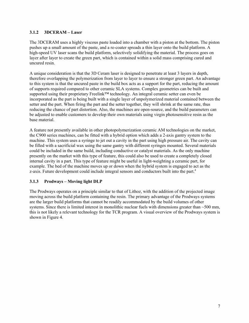
The Prodways operates on a principle similar to that of Lithoz, with the addition of the projected image moving across the build platform containing the resin. The primary advantage of the Prodways systems are the larger build platforms that cannot be readily accommodated by the build volumes of other systems. Since there is limited interest in monolithic nuclear fuels with dimensions greater than ~500 mm, this is not likely a relevant technology for the TCR program. A visual overview of the Prodways system is shown in Figure 4.
8
3.1.4 Admatec – DLP
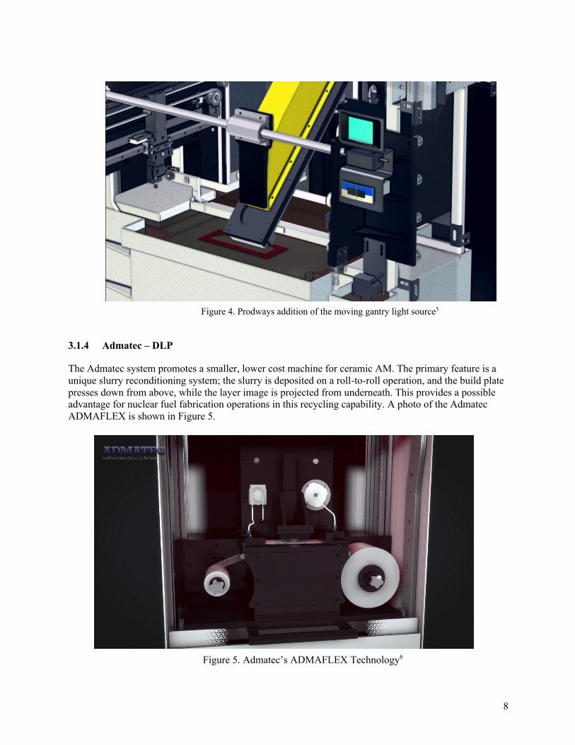
The Admatec system promotes a smaller, lower cost machine for ceramic AM. The primary feature is a unique slurry reconditioning system; the slurry is deposited on a roll-to-roll operation, and the build plate presses down from above, while the layer image is projected from underneath. This provides a possible advantage for nuclear fuel fabrication operations in this recycling capability. A photo of the Admatec ADMAFLEX is shown in Figure 5.
Figure 5. Admatec’s ADMAFLEX Technology6
Figure 4. Prodways addition of the moving gantry light source5

9
3.1.5 Advantages and Disadvantages of Photopolymerization
The most common initial points of comparison for photopolymerization systems are build size and resolution. Laser-based systems can offer a larger printing area and are applicable to machine box dimensions of approximately 500 × 500 mm, with a resolution of 35–50 µm. The overall build dimension is clearly adequate for all realistic monolithic nuclear fuels. The resolution capabilities will ultimately be dictated by the sensitivity of fuel performance to the desired dimensions imparted by the fabrication process. Laser-based systems provide better homogeneity to the fabricated part, having a constant exposure output on the entire build layer surface. This more homogeneous green density leads directly to more homogenous sintering shrinkage. DLP-based technologies rely on very accurate shaping of the pattern and are subject to slight distortions across the whole surface, leading to less homogeneous sintering shrinkage and resulting residual internal stresses. DLP-based technologies are inherently faster. A tradeoff exists between higher speed and lower quality parts versus slower speeds and higher quality parts, which is true of many fabrication processes. When analyzing photopolymerization ceramic AM compared to other types of AM and modern manufacturing, the limitations of employing some ceramic materials must be considered. In their simplest forms, all photopolymerization technologies involve loading fine ceramic powders into a transparent resin that must react with a certain wavelength range of light to polymerize and harden. The solids loading percentage—along with the color, size, and shape of the particles—will have some effect on this reaction. Light can be absorbed or scattered uncontrollably each time a new ceramic formulation is developed. The designer and ultimately the end-user must be prepared to spend a significant amount of time to optimize the machine settings to tune the process to the desired powder composition. This is of particular relevance to nuclear fuel fabrication. Uranium dioxide powders are not white as are many of the inert oxide powders outlined in Section 4. Stoichiometric UO2 is brown-orange, while hyperstoichiometric UO2 and other higher uranium oxides (e.g., U3O8) are black.
3.2 BINDER JET TECHNOLOGIES
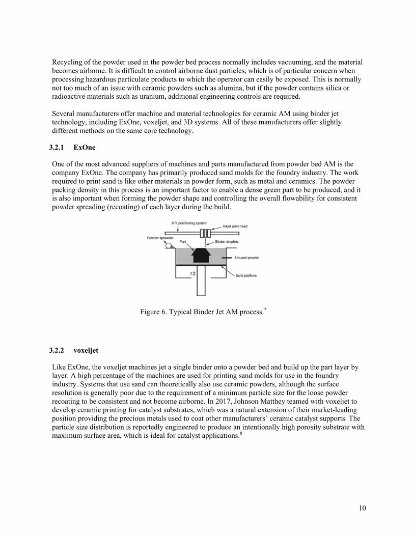
The powder-bed binder jet process produces a green part by jetting a binder onto a powder bed, gluing powder particles together layer by layer. One of the main advantages to this class of ceramic AM technologies is its ability to create large parts at a relatively high speed. While the photopolymerization technologies are targeting the technical ceramics segment, the binder jet technology is more suited to traditional ceramic manufacturing applications. Since the part is inherently contained within the powder bed during the build, no support structure is required. The green parts are removed from the loose powder bed, and the unbound powder can be recycled easily. Most of the research performed to date on binder jet AM has been with metal powders, while very little research has been performed on ceramic materials. The metal industry is much larger than the ceramic industry and has the advantage of an already established production route in the powder metal industry that can be used to de-bind and sinter the powder bed AM parts. As in existing modern ceramic manufacturing, the powder metallurgy manufacturing process uses organic binders and lubricants mixed with metal powder that is pressed into parts using high tonnage hydraulic or servo electric presses at very high speeds. In powder-bed binder jet AM, like most of the photopolymerization technologies (except 3DCeram), it is not possible to leave an internal closed void. This is because there must be a way to remove the loose powder, so an exit hole must be designed into the part to allow for powder removal. This is often not desirable and can compromise the integrity of the design. However, open-ended channels can be designed into the part, and the excess powder can be poured out, or dry compressed air can be used for total removal.
10
Recycling of the powder used in the powder bed process normally includes vacuuming, and the material becomes airborne. It is difficult to control airborne dust particles, which is of particular concern when processing hazardous particulate products to which the operator can easily be exposed. This is normally not too much of an issue with ceramic powders such as alumina, but if the powder contains silica or radioactive materials such as uranium, additional engineering controls are required.
Several manufacturers offer machine and material technologies for ceramic AM using binder jet technology, including ExOne, voxeljet, and 3D systems. All of these manufacturers offer slightly different methods on the same core technology.
3.2.1 ExOne
One of the most advanced suppliers of machines and parts manufactured from powder bed AM is the company ExOne. The company has primarily produced sand molds for the foundry industry. The work required to print sand is like other materials in powder form, such as metal and ceramics. The powder packing density in this process is an important factor to enable a dense green part to be produced, and it is also important when forming the powder shape and controlling the overall flowability for consistent powder spreading (recoating) of each layer during the build.
3.2.2 voxeljet
Like ExOne, the voxeljet machines jet a single binder onto a powder bed and build up the part layer by layer. A high percentage of the machines are used for printing sand molds for use in the foundry industry. Systems that use sand can theoretically also use ceramic powders, although the surface resolution is generally poor due to the requirement of a minimum particle size for the loose powder recoating to be consistent and not become airborne. In 2017, Johnson Matthey teamed with voxeljet to develop ceramic printing for catalyst substrates, which was a natural extension of their market-leading position providing the precious metals used to coat other manufacturers’ ceramic catalyst supports. The particle size distribution is reportedly engineered to produce an intentionally high porosity substrate with maximum surface area, which is ideal for catalyst applications.8
Figure 6. Typical Binder Jet AM process.7
11
3.2.3 3D Systems
3D Systems pioneered AM with the invention of SLA using photo sensitive resins. The company expanded its offering in the 1990s and early 2000s with the acquisition of several companies and through internal development of other technologies. More recently, they acquired companies such as LayerWise, Cimatron, BotObjects and Nextdent. In all, 3D Systems has acquired approximately 29 companies.
Their main focus for machine offerings is currently for metal, wax, sand, and plastic materials. The metal technology is selective laser sintering and is well developed. The machine offering for metal is quite broad, with some machines being developed for specific industries such as dental. The wax machines target the investment casting industry in this relatively new concept. Wax patterns can be printed directly and in volume by the Multi Jet Printer (MJP) and fitted with established processes in smaller investment-casting foundries. The sand printers can print in color, a technology was originally developed by Z Corporation, and they are generally useful for educational modeling purposes. The plastic printers are MJP type printers available in many different sizes. As the parts are built, a secondary wax material is deposited around the model to support it. Once the model is complete, the wax is melted away to leave the finished model, avoiding the need to remove supports. At the present time, there is no reported push into ceramic AM by the company.
3.3 MATERIAL EXTRUSION TECHNOLOGIES
Ceramic pastes and filaments are the primary product form used in material extrusion AM technologies. This class of ceramic AM has many end-use applications, ranging from large-area format cement structures to small porous bioceramics such as bone scaffold. The companies listed in Table 1 are all working on variations and application-specific technologies to force the prepared material through a die to build the part layer by layer. However, in the context of this report, this type of ceramic AM can be deemed low resolution technology for the foreseeable future and is not suited for high-volume traditional or technical ceramics manufacturing.
For example, French company Nanoe has been developing a ceramic filament technology named Zetamix which consists of spools of a CIM-based ceramic material that can be universally fed into many of the material extrusion machines currently on the market. The solids loading of their filament is reportedly quite high at around 85–90 wt. %, and sintered parts from their standard offerings of alumina and stabilized zirconia approach full density at around 99%. Additionally, the company has recently released the Zetaprint small desktop FDM printer specifically designed for use with their Zetamix filaments, with a price point less than $20,000. While Nanoe is the first company to release a ceramic filament, the overall poor resolution and slow speed of this type of technology most likely relegates it to small prototype and modeling operations rather than being a serious option for technical ceramics manufacturing. It is notable that the company was founded in 2008 and has established itself as a solid technical ceramic powder producer offering raw and ready-to-press alumina, zirconia, and alumina-zirconia mixtures. As part of its growth strategy, Nanoe has entered the ceramic AM market by adopting its nanometer-scale ceramic powder for use with the filament and now has the machine product offering.
3.4 POWDER BED FUSION TECHNOLOGIES
Metal additive parts can be produced using several different methods, including ion beam, selective laser sintering (SLS), and powder bed binder jet. Ion beam and SLS are also known as directly sintered processes. The ion beam method and the selective laser sintering both result in an almost fully dense part being produced directly from the machine. The result of the high density is largely due to the investment in R&D that powder metal suppliers have made in the powder processing production methods. The main difference between directly sintered and standard de-bind and sinter when applied to metals is processing

12
speed. The directly sintered process is faster to get to the finished part, but the time to finished product also depends on the support structure complexity. This can result in extended removal/finishing time. There is often more material in the support structure than in the part, and this can add significant cost to the overall process.
It is difficult to directly sinter ceramic materials due to the complex phases through which the material must pass during heating. Laser energy is also easily absorbed into many ceramic powders, inhibiting the high temperatures required to achieve the desired material properties. A major difference between using metal SLS and applying the technique to ceramics is the durability of thermal shock when heating and cooling rapidly. Metal can easily withstand this process, but ceramic may crack.
3.4.1 HP
HP has been specifically developing a ceramic AM technology based on CIM. The technology is derived from their more developed metal injection molded (MIM) and uses three or more printer heads that can print two materials. In one pass, the print head lays a fusion agent over the entire required layer shape and adds a detailing agent around the edge of the part to achieve high precision edges. During the build, the entire build chamber operates at elevated temperatures. A secondary heat source is attached to the print head and adds the final required heat to fully fuse the material, trailing the jetting heads as it moves across the powder bed. The advantage of these printers over competitors’ printers is speed. The HP printers jet binder in both directions and accurately form layers of 75 µm resolution at elevated speeds.
The company has reportedly been successful in creating extremely high resolution, high density ceramic parts as a result of the technology using a low content of organic binder, distinguishing it from the other technologies discussed above. HP has recently introduced its MIM technology, building on its decades of experience in inkjet technology, and HP has the expertise to introduce a high degree of flexibility and scalability to eventually support a successful push into ceramics AM. HP’s Multi Jet Fusion technology is targeted towards the large, industrial high-speed AM segment. Its first offering was nylon powder, and more recently, HP has been able to demonstrate success using metal and ceramic powders. The company does not have much publicly information available on ceramic materials, but it is possible that they could make a serious push into the directly sintered porcelain and technical ceramics industry.8
3.4.2 Osseomatrix
The French company Osseomatrix has been developing medical-based ceramics by SLS. As the only company to directly laser sinter ceramic powder, the company refers to the bonding method as fusing. On review of the published patents, the powder mix includes a laser energy–absorbing frittable material.9 The machines are currently purpose-built for the medical implant industry. The company is targeting patient-specific bioceramic implants to treat orthopedic and craniomaxillofacial bone loss, but little information is available on how widely this technology has been able to impact the market. Osseomatrix is focusing on an integrated solution from scans to ready-to-implant parts as a service bureau to the medical industry. Since the implant and bone reconstruction application requires a high-porosity and bioresorbable material, it is entirely possible that the issues of applying SLS to technical ceramics are not an obstacle for this niche industry. There are some advantages in not having to use an organic binder and not needing to subject green parts to the kiln for medical parts in which absolute purity and control of the process is critical.

13
3.5 MATERIAL JETTING TECHNOLOGIES
The Israeli company XJet has developed a different technology using binder jetting. It could be considered a hybrid, as the build method is similar to extrusion deposition. The XJet system is comprised of nanometer-sized particles dispersed in a liquid suspension. The liquid is then pushed through a head like an inkjet and deposited on a build plate layer by layer. To prevent distortion, a support structure must be built at the same time that the part is being built. The support structure is removed once the part is built, while still in the green state. The part is then cured in a de-binding kiln and is subsequently fired to temperature as in other AM technologies.
As with any fine ceramic particle, the major disadvantage is high shrinkage during firing. The more complex the part, the greater the risk of defects. Therefore, limitations of design exist, and attention must be paid to joining surfaces when initially designing the part. Any material used in this process must be converted into nanoparticles. This can be challenging, and the advantage of the system does not seem to warrant the amount of processing required for the raw material for nonstandard materials. If the material is already available on the open market in nanoparticle form, then it can easily be formulated to work in the machine. When nanoparticles are in the form of a dry powder, they can also be difficult to control from a safety perspective, and manufacturing in-house jettable materials could prove difficult.

14
4. ASSESSMENT OF DISCUSSED AM TECHNOLOGIES FOR CERAMIC FUEL FABRICATION
As described in the sections above, the success of modern ceramic manufacturing is highly dependent on the properties of the starting powders, especially when dealing with technical ceramics. A major emphasis of the TCR program is to evaluate methodologies suitable for fabrication of UO2, a material that behaves much like a conventional ceramic material from a processing point of view. However, other nuclear fuels such as uranium mononitride (UN) and uranium monocarbide (UC) behave more like technical ceramics. Additive manufacturing of UO2 is therefore likely to be accomplished through the use of significantly different machines and methods than for nitride or carbide fuels.
Photopolymerization AM technologies target the technical ceramic segments of the market since this is where the greatest impact and future growth lies. The photocurable resins at the heart of this class of ceramic AM technologies are sourced from the existing supply chain of polymer AM technology, and in most cases, they are being adapted to ceramics. These resin systems are simply loaded with fine ceramic powders. this must be balanced with the fact that if the solids loading is too high, then the light polymerization could be inhibited or could behave in different ways than expected. Therefore, extensive development work is required of the offeror of a “ready-to-print” ceramic resin in a given machine for a given part geometry, and a universally accepted standard will be difficult to attain.
For a given end-user application, the following general steps would be necessary for obtaining a robust process verification on other-than-prototypical parts. This assumes that the intended part geometry meets the initial criteria for minimum/maximum feature size (wall thickness, holes, part support during the build, provisions for unreacted material removal, etc.)
• Verify the raw powder properties of particle size distribution, particle shape, density, and specific
surface area • Determine resin/paste viscosity curve vs. solids loading (by volume or weight) by performing
trial mixing (Photopolymerization/Material Extrusion/Material Jetting) • Determine if any stabilizing agents needed to be incorporated into the paste • Perform initial printing trials to determine machine variables (layer thickness, UV power output
setting, build speed, requirement of any part support [Photopolymerization/Material Extrusion/Material Jetting])
• Perform initial printing trials to determine machine variables (loose powder spreading performance, layer thickness, build speed [Binder jetting/Powder Bed Fusion])
• Implement part removal from the machine and post-print cleaning trials to determine if there are any issues with the initial print and visual observation of surface resolution and defects
• Conduct de-bind studies, including maximum rate, part measurement for distortion effects • Conduct sintering studies to determine temperature and atmosphere profiles, if required • Perform part surface finishing if necessary to meet required tolerances for surface
roughness/flatness • Measure post-sinter part dimensions and compare them to available historical reference models • Make corrections to the to part model as needed • Repeat printing/de-binding/sintering/post-processing steps until the print parameters match the
finished part specifications
Specific to the photopolymerization technologies, the solids-loading of the resin varies from manufacturer to manufacturer. The higher the solids loading, the less sintering shrinkage would be

15
expected, with powder packing also being a factor. The above-mentioned companies have a ceramic solids-loading (volume %) in the offered resins, as follows:
Table 3. Solids-loading reported by various polymerization technology manufacturers.
Company Solids-loading (volume percent) Lithoz 40–55 Prodways Not provided Admatec 40–45 3DCERAM 55–65
Ceramic materials are generally classified into two main groups: oxides and non-oxides. The most important oxide materials involve pure forms of alumina, zirconia, and silica and mixes between them. The important non-oxides are comprised of aluminum, zirconium, and silicon combined with nitrogen, carbon, or boron (nitrides, carbides, and borides). Cermets are a class of materials with properties of both metals and ceramics and are generally metallic carbides, silicides, and other unique compounds. In addition to the materials above, biomedical and cement applications include calcium and phosphorous-based compounds, while glasses and clays are mixtures of minerals that are processed to react and form complex amorphous or crystalline phases. The current materials available for commercial ceramic AM are as described below.
4.1 ALUMINUM OXIDE (AL2O3)
Alumina is one of the most important oxide ceramic materials and is characterized by high levels of hardness, as well as good corrosion and temperature resistance, at a relatively low cost. Components made from alumina are electrically and thermally insulating and are therefore suitable for a wide range of applications such as substrates in the electronics industry, thread guides in textile engineering, protection in thermal processes, and many others. Many technical ceramic manufactures have formulated very specific grades of alumina products with anywhere from 92% to 99.99% alumina content and have thoroughly characterized the resultant properties. Some grades are specifically tailored to specific dielectric applications, while others are optimized for specific hardness and wear properties.
4.2 ZIRCONIUM OXIDE (ZRO2)
Zirconia is used for applications with extreme demands on the material. High-end metal forming, valves, bearings, and cutting tools are some of the applications which benefit from the mechanical properties of zirconia. The biocompatibility of zirconia facilitates its use in medical and dental applications and as part of permanent implants. Zirconia can exist in varying crystal forms, depending on temperature, and thus stabilizing additives such as yttria, magnesia, and ceria, are typically used. 3 and 8 mol Y-stabilized zirconia (3/8YSZ) are the most common grades. Depending on the additive and the sintering process used, color for zirconia can range from bright white, to yellow/tan, to black.
4.3 SILICON NITRIDE (SI3N4)
Silicon nitride exhibits superior material properties such as high strength, high toughness, thermal shock resistance, low thermal conductivity, good electrical conductivity and good chemical resistance to corrosion by many acids and alkalis. It has a wide range of applications, including insulators, heating elements, bearings, impellers and more. Furthermore, it can be used for the medical engineering of permanent implants due to its osseointegrative potential and anti-infective properties.

16
4.4 SILICON CARBIDE (SIC)
Silicon carbide is an important technical ceramic, yet it has not been extensively used in ceramic AM to date. It is valued for its high hardness, electrical, and thermal conductivity properties, along with its low density. Important applications are heating elements, abrasives for grinding and cutting, wear-resistance components, and increasingly as a component in ceramic matrix composites for aerospace. The TCR program is actively developing a combination of a binder jet and chemical vapor infiltration processes for producing high density SiC.
4.5 TRICALCIUM PHOSPHATE
Tricalcium phosphate exhibits excellent biocompatibility, bioresorbability and osteoconductivity, and is therefore a well-established material for bone replacement in regenerative medicine. Due to its properties, it is possible to manufacture patient-specific resorbable implants with defined pore structures and geometries using this material. During the healing phase, these implants will be resorbed by the body and replaced by native bone tissue, so a second surgery to remove the implant is not necessary.
4.6 HYDROXYAPATITE (HAP)
Hydroxyapatite is a naturally occurring mineral that forms the main component of bones. Due to its similarities to the inorganic components of bone, HAP possesses excellent biocompatibility and osteoconductivity and has a number of potential applications as a bone substitute. In comparison to tricalcium phosphate, hydroxyapatite takes far more time to be absorbed into the body, therefore giving the body more time to heal. Using HAP, ceramic AM can be used to manufacture patient-specific bioresorbable implants with defined pore structures and geometries. Like TCP, these implants will be reabsorbed by the body and will be replaced by native bone tissue, so the implant does not need to be removed once the healing process is finished.
4.7 SILICA-BASED MATERIALS FOR CASTING CORES
Modern investment casting of metals relies heavily on leachable ceramic cores of various formulations, depending on the metal alloy being cast. Formulations are a closely guarded trade secret in many instances, but a common one is silica with minor additions of alumina and zircon. Typical applications include single crystal casting of turbine blades. Sintered ceramic core properties are typically characterized as having very low thermal expansion at the casting temperature, a high porosity, outstanding surface quality, and a very good leachability.

17
5. TECHNOLOGY LIMITATIONS
Industry adoption of ceramic AM to replace mass-production faces serious technical and economic challenges. While it is clearly a technology that is well suited to some applications, much advancement will be required to begin to meaningfully penetrate modern ceramic manufacturing industries.
5.1 MATERIAL PREPARATION FOR ADDITIVE MANUFACTURING
As discussed in more detail above, the finished ceramic part property is highly dependent on the characteristics of the starting powder. Technical ceramics typically use starting raw powder particle sizes of 0.5 µm to 2 µm to achieve a high degree of sintered density, high strength and fracture toughness, and surface finish. During the sintering process, the particles fuse and form grains, and the key to achieving the excellent mechanical and electrical properties is the limitation of grain growth during the sintering process. Therefore, along with the raw powder, a ceramic powder formulation that is fed into the forming process has undergone extensive preparation, including further milling to increase the surface area, addition of specialized dopants, and then agglomeration to a free-flowing, low-dust powder (in the case of pressing). Casting, extrusion, and CIM transform the powder formulation into a slurry, paste, or pellets, which is introduced into the forming machine.
In preparing powders for ceramic AM, the current industry practice is for the machine operators to offer a standard mix been optimized for the particular machine. Therefore, for example, only one or two alumina grades are offered, and the typical finished part properties are sometimes characterized in data sheets. This type of business model is sufficient for low volume prototyping by non-ceramic material engineers, but eventual end-use ceramic manufacturers will be required to develop their proprietary formulations to the type of printer, and this may limit adoption in the short term. Additives specifically meant to impart high green strength, to keep particles in suspension, or to serve as sintering aids must be reformulated to achieve the particular viscosity and other specific parameters that the machine would require. In the instance or the photopolymerization machine types, the interactions of the laser light with particle size and shape would be completely unknown and would need to be qualified by the manufacturer. Different types of high-shear mixing and resin-handling equipment would also be necessary, but this is not current practice in most ceramic manufacturing operations. In the case of photopolymerizaton AM, the use of dark powder materials such as silicon carbide, boron carbide, and other specialized oxides and non-oxides appears highly limited due to absorption of a portion of the light spectrum by the powder. If a high proportion of the light source is absorbed by the powder and not by the resin, then the layer thickness and print speed could be impacted, as well as the strength of the green part.
5.2 PRINTING
The main selling feature of ceramic AM machines is that it is possible to form complex geometries not attainable by current forming processes. The elimination of tooling required in such other forming operations like pressing, casting, extrusion, and CIM is another major differentiating attribute. In the vast majority of the ceramic industry, the geometry limitation of a customer is seldom an issue and is limited to a minority of the applications. High complexity part geometries are possible with CIM, although the upfront tooling cost is high. Therefore, prototyping and low volume part runs are one of the early market adoption opportunities for ceramic AM. Many technical ceramic applications evolved as replacements for previously used metal parts. It is not unusual for ceramic parts with complex geometries to be

18
designed from multiple pieces and joined and even metallized for straightforward joining to metal parts. Current limitations in ceramic AM include the actual print speed for more than a few parts at once, the batch-to-batch inconsistency that may arise due to the small machine size, the requirement to load/re-load material into the machine interface, and the recycling of the unused powder and the resulting quality of this operation.
5.3 POST-PRINTING
Many of the ceramic AM technologies require separating the green part from the unused/un-reacted feedstock. In some cases, this is a dry powder operation that involves compressed air blowing, vacuuming, and labor intensive hand-work. In other application, it involves wet processing using solvents and hand tools to chemically or physically separate the part from the supporting material. This is typically performed in a separate workstation from the printer and requires some method to collect and reprocess the feedstock that was not formed into the green part. Compared to modern pressing, casting, extrusion, and CIM operation, in which the part usually exits the forming process and immediately proceeds to the next step, post-print operations are one of the most limiting process steps facing widespread ceramic AM adoption.
After the green parts are separated, they are then subjected to a debinding process similar to processes used in more traditional ceramic manufacturing. However, in dry-pressing, casting, and extrusion, it is typical to have a 1–5% maximum organic binder fraction that must be removed as compared to the very high levels required in most ceramic AM technologies. CIM involves similar levels of organic binder, and the manufacturers using CIM have optimized the process through the use of specialized catalytic or thermal profiles prior to sintering to minimize defects. In the leachable ceramic cores industry, it is standard practice to manufacture refractory setters with the same part profile or to entirely encase the parts in a loose granular ceramic power to provide part support during the de-bind and sintering processes. One major difficulty in having a high binder content is the corresponding long de-bind time and the potential for defects due to gas evolution from within the part. In ceramic AM, a significant current limitation is maximum wall thickness due to the de-bind step. For example, in CIM a polyacetal-based binder is often used and is removed quickly with an ammonia gas-based thermal decomposition process that does not require specialized part support.

19
6. CONCLUSIONS AND RECOMMENDATIONS FOR FUTURE ASSESSMENTS FOR NUCLEAR FUEL FABRICATION
The nascent field of ceramic AM encompasses a suite of machine and materials technologies that can vary significantly, depending on the material and the part geometry being produced. Designers and manufacturers today have a wide range of available tools at their disposal, and AM is finding a place within various industries where its advantages can be realized. However, it must be recognized that significant limitations in both the technology and the economics exist in this industry today. The technology is still in its relative infancy with respect to ceramic materials, but there are successful applications in which the combination of novel geometry capabilities and time-to-produce have to be recognized. For applications with existing mature high-volume manufacturing operations, the ability of AM to have a significant impact may be limited by the high capital and material costs for the foreseeable future. New ceramic manufacturing opportunities where AM can offer freedom-of-design to meet complex geometry requirements will have a far greater chance of success. Furthermore, operations that could benefit greatly from remote or on-demand ceramic part production (space exploration, nuclear, aerospace) due to very high part value or environmental restrictions on personnel could offer a compelling case to consider one of the technologies described herein. Adaptation of the AM methods described in this report for UO2 or other uranium ceramics is likely to occur in two areas. First, methods such as binder jet may be capable of fabricating low density or otherwise engineered architectures or relevance for subsequent fabrication processes. However, it is unlikely that binderjet methods will be capable of yielding densities and microstructures comparable to those achievable using reference conventional fabrication processes. Conversely, DLP methods have a high potential for production of high density monolithic fuels with engineered features. The challenge in adaptation of these systems for uranium materials lies in overcoming commercial reference methods developed for traditional oxide ceramics and operations not concerned with radiological hazards.

20
7. REFERENCES
1. A. Nelson, “Features that further performance limits of nuclear fuel fabrication: opportunities for
additive manufacturing of nuclear fuels” ORNL/SPR-2019/1183. May 2019. 2. 3DCeram presentation documents 3. Lithoz website, http://Lithoz.com/en 4. 3DCeram website, http://3dceram.com/en 5. Prodways website, http://prodways.com/en 6. Admatec website, http://admateceurope.com 7. Dini, F. et al, “A review of binder jet process parameters; powder, binder, printing and sintering
condition”, Metal Powder Report, 23 May 2019 8. “Ceramic Additive Manufacturing Markets 2017–2028”, SmarTech Publishing, September 2018 9. Christophe Colin, Jean-Dominique Bartout, Emmanuelle Shaker, David Marchat, Didier Nimal,
European Patent Application EP2784045A1, “Selective laser sintering/melting process”, OSSEOMATRIX ARMINES Assoc pour Recherche et Dev des Methodes et Process Ind