Embed Size (px)
Citation preview
21J. Kang (ed.), Assessment of the Nuclear Programs of Iran and North Korea, DOI 10.1007/978-94-007-6019-6_2, © Springer Science+Business Media Dordrecht 2013
1 Introduction
This chapter contains a technical analysis of the 100 MWth LWR (in the event of its successful construction) and the Yongbyon uranium enrichment plant that constitute the DPRK’s main nuclear facilities. The analysis is primarily based on a November 12, 2010 meeting between Dr. Siegfried Hecker, the former director of Los Alamos National Laboratory, who is currently with Stanford University, USA, and North Korean of fi cials. During this meeting, North Korean Of fi cials disclosed the existence of an experimental light water reactor (LWR) program and uranium enrichment facility. The chapter also describes a veri fi cation methodology for the entire DPRK nuclear program, including sites, methods and overarching objectives.
2 The DPRK’s New Nuclear Facilities
2.1 100 MWth LWR
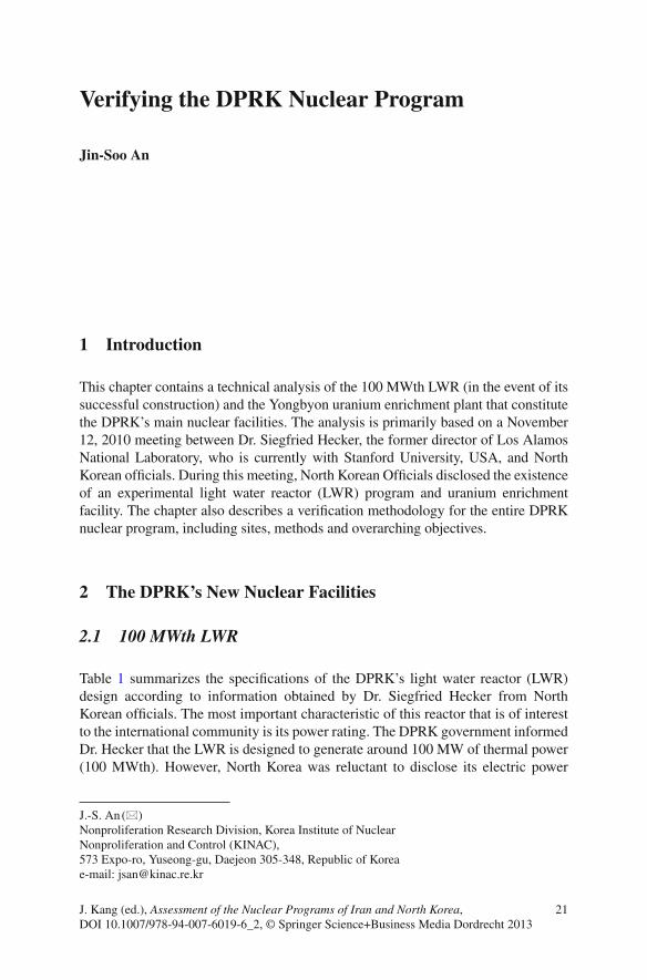
Table 1 summarizes the speci fi cations of the DPRK’s light water reactor (LWR) design according to information obtained by Dr. Siegfried Hecker from North Korean of fi cials. The most important characteristic of this reactor that is of interest to the international community is its power rating. The DPRK government informed Dr. Hecker that the LWR is designed to generate around 100 MW of thermal power (100 MWth). However, North Korea was reluctant to disclose its electric power
Verifying the DPRK Nuclear Program
Jin-Soo An
J.-S. An (*) Nonproliferation Research Division, Korea Institute of Nuclear Nonproliferation and Control (KINAC) , 573 Expo-ro , Yuseong-gu, Daejeon 305-348 , Republic of Korea e-mail: [email protected]
22 J.-S. An
generation capacity and instead said that thermal ef fi ciency (the transformational ef fi ciency from heat power to electric power) was approximately 30%. Accordingly, Dr. Hecker estimates the LWR’s electric power at around 25–30 MWe (Hecker 2010 ) .
According to Dr. Hecker, DPRK of fi cials declared that they had independently fabricated reactor-related parts, including the reactor vessel, pumps and LWR fuel, and that the DPRK possesses suf fi cient uranium ore reserves to fuel the reactor. They also said that research into the manufacture of uranium-dioxide (UO
2 )-type
fuel was currently in progress and that North Korea would soon initiate domestic UO
2 manufacture without external support. In addition, DPRK of fi cials reported
that they had not decided upon whether to use zircaloy or stainless steel for the clad-ding. Other details, such as operating pressure and temperature, coolant fl ow rate, as well as information about the moderator and burn-up rate were not veri fi ed.
The primary system of the LWR, such as the reactor vessel, should be capable of enduring high temperature and pressure. Therefore, LWR fabrication necessarily requires high levels of technology and substantial experience. However, some of these challenges can be mitigated by decreasing the target heat ef fi ciency of the power plant because that would diminish the heat and pressure burden on the primary system.
North Korean of fi cials were especially reluctant to disclose speci fi c electric power generation capabilities to Dr. Hecker. This could be due to equipment perfor-mance defects, construction problems or a general reluctance to admit shortcomings in their LWR fabrication program.
2.2 Uranium Enrichment Facility
According to what North Korean of fi cials told Dr. Hecker on November 12, 2010, the uranium enrichment facility had been built in April 2009 and begun operation in early November 2010, several days prior to Dr. Hecker’s visit to North Korea. Dr. Hecker reported that he saw panels and LED displays within the facility’s control
Table 1 Yongbyon 100 MWth LWR: known speci fi cations
Thermal power 100 MW th
Heat ef fi ciency ~30% Estimated by DPRK scientist Electric power 25–30 MW
e Estimated by Hecker
Fuel type UO 2 Cladding material not fi xed
as of December 2010. Fuel enrichment Average 3.5% (2.2–4%) Fuel 1 core Quantity
(U base) 4,000 kg
Pressure vessel High-strength steel Possibly with a stainless steel liner
Containment vessel ~ D: 22 m, H: 40 m, Thick : 0.9 m
Reinforced concrete
23Verifying the DPRK Nuclear Program
room listing operating parameters. Hecker also reported that the facility had fi ve large panels toward the rear that had numerous LED displays with similar opera-tional information.
North Korea argues that this enrichment facility is intended to supply fuel (3.5% low enriched uranium) to their experimental LWR, which is currently under construction. The points below summarize characteristics of the enrichment facility that are either known or estimable:
Location: Yongbyon Nuclear Fuel Fabrication Plant (re-modeled U-metal manu-• facturing facility, 39.7701 N, 125.7493 E) Chronology:•
Commencement of Construction: April 2009 – Commencement of Operation: Early November 2010 –
Building Size: 120 m × 18 m (two story building) • Capacity: 8,000 kg-SWU/year (per North Korean announcement) • Number of Centrifuges/Cascades/Zone: 2,000/6/2 • Centrifuge Speci fi cations:•
Type: P-2 – 1 (G-2) Outside Diameter: about 20 cm (8 in.) – Height: About 1.8 m (6 ft) – Enrichment Capacity: About 4 kg-SWU/year – Rotor: Iron alloy (Possibly maraging steel) – Case: Aluminum (Probably?) –
Enrichment Level of Product/Tail: Average 3.5%/0.27% • Enriched Uranium Production Capacity (estimated value)•
LEU (3.5%): about 1,800 kg/year – HEU (90%): about 40 kg/year –
Based on disclosed information regarding the Yongbyon enrichment facility, it is possible to deduce the following with regard to the DPRK’s uranium enrichment program:
Since North Korea was able to build centrifuges on the above-mentioned scale • within the relatively short period of one and half years, there could be separate enrichment facilities in another location. Also, the North could build additional clandestine enrichment facilities in the future. Although North Korea reported that it operates all 2,000 centrifuges in the enrich-• ment facility, based on other cases (such as Iran), it is probable that the DPRK will experience dif fi culties in operating centrifuges on this scale.
1 Dr. Hecker reported that North Korea were “most likely” to be “P-2 centrifuges (which were based on the German G-2, that was developed by the Germans as part of the URENCO consor-tium), which typically have high-strength maraging steel rotors that can by spun much faster than the aluminum rotors, thereby increasing the throughput.”
24 J.-S. An
Even though North Korea argues that this facility is intended for the production • of low enriched uranium, the facility could easily be diverted to produce HEU for nuclear weapons. If diverted, the facility could produce around 40 kg of HEU per year, from which one or two HEU bombs could be manufactured. In the context of negotiations over denuclearization, verifying DPRK compli-• ance with any eventual agreement will be dif fi cult. North Korea is not eager to abandon its uranium enrichment program and continues to justify its ongoing nuclear program under the guise of the peaceful pursuit of nuclear power.
3 Veri fi cation
The purpose of veri fi cation is to verify a nation’s reported nuclear-related activities and con fi rm non-existence of un-declared activities.
3.1 Programs and Items to Verify
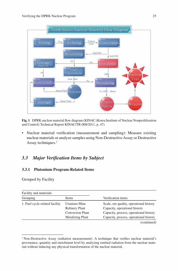
Issues related to DPRK nuclear veri fi cation can be broadly grouped into (a) the plu-tonium production program, (b) the uranium enrichment program, and (c) the nuclear weapons production program. The complete veri fi cation of North Korea’s nuclear weapons development program, based on Fig. 1 , requires the veri fi cation of:
the history and current status of all nuclear materials that North Korea has • produced, stored or used the history of development of nuclear weapons and their current status • the history and current status of facilities and equipment used for nuclear weapons • development the facilities that manufacture equipment that is used for nuclear weapon • development the current status of human power, especially scientists and engineers, involved • in nuclear weapon related activities
3.2 Major Veri fi cation Methods
In order to verify DPRK compliance, it is necessary to inspect documents, conduct extensive interviews with people involved in the associated programs, and perform nuclear material measurement and sampling.
Document inspection: Match reported data with actual operational records, • verify design information, compare the information in documents with measure-ments on existing nuclear materials and the measurement management record. Record and interview: Photograph and interview key personnel in order to verify • facility scale, instruments, and organizational manpower.
25Verifying the DPRK Nuclear Program
Nuclear material veri fi cation (measurement and sampling): Measure existing • nuclear materials or analyze samples using Non-Destructive Assay or Destructive Assay techniques. 2
3.3 Major Veri fi cation Items by Subject
3.3.1 Plutonium Program-Related Items
Grouped by Facility
Facility and materials
Grouping Items Veri fi cation items
1. Fuel cycle-related facility Uranium Mine Scale, ore quality, operational history Re fi nery Plant Capacity, operational history Conversion Plant Capacity, process, operational history Metalizing Plant Capacity, process, operational history
(continued)
2 Non-Destructive Assay (radiation measurement): A technique that verifies nuclear material’s provenance, quantity and enrichment level by analyzing emitted radiation from the nuclear mate-rial without inducing any physical transformation of the nuclear material.
Fig. 1 DPRK nuclear material fl ow diagram (KINAC (Korea Institute of Nuclear Nonproliferation and Control) Technical Report KINAC/TR-008/2011, p. 47)
26 J.-S. An
– Destructive Assay (chemical analysis): A technique that verifies a nuclear material’s quantity or isotope ratio by sampling a portion of the nuclear material itself or by using an environmental sample from the vicinity of the facility and measuring chemical properties.
– Other techniques: Measure the physical properties of tested sample (weight, thickness of the container, density, etc.)
Facility and materials
Grouping Items Veri fi cation items
2. Nuclear materials Natural Uranium Stock, chemical form, history Plutonium Stock, isotope composition/ratio,
chemical form, history Fuel (New Fuel) Stock, history
3. Reactor 5 MWe GMR Operational history (including thermal power), Spent fuel history
50 MWe GMR Present state 200 MWe GMR Present state IRT-2000 Operational history, spent fuel history,
nuclear material irradiation history Critical Device Operational history and present state
4. Spent fuel 5 MWe Spent Fuel Quantity produced, burn-up, present state, quantity reprocessed
IRT-2000 Spent Fuel Quantity, burn-up, present state 5. Reprocessing plant Radio-chemical
Experimental Laboratory
Capacity, operational history, quantity of recovered Pu
HLW a Storage Facility HLW quantity and composition MLW b Storage Facility MLW quantity and composition
6. Research facility Yongbyon Nuclear Research Center
Scale of facility, substance of study
Universities ” Other Nuclear Research
Laboratories ”
7. Materials and instrument manufacturing facility
Reactor Instruments Scale, instrument production quantity and quality
Uranium Production Related Materials and Instruments
”
Reprocessing-Related Materials and Instruments
”
Import Materials and Instruments
Verify quantity imported, used, and stocked
8. Workers Human Power and Organization
Past and present state veri fi cation
Interview Activity veri fi cation
(continued)
a High level radioactive waste b Medium level radioactive waste
27Verifying the DPRK Nuclear Program
Materials to Verify
Material Use Remarks
1 Uranium ore Uranium production Mine scale, ore quantity and quality, gangue quantity
2 Yellow cake Uranium production TBP, HNO 3 , H
2 SO
4 , etc.
3 UF 4 Uranium metalizing
or F 6 production
HF, F 2 , CaF
2 , H
2 SO
4 , etc.
4 UF 6 Enrichment ”
5 Uranium metal Fuel production Electric furnace, Ca and/or Mg metal powder 6 Fuel rod Reactor operation Fuel fabrication facility, cladding materials 7 Spent fuel Pu production Reprocessing plant, TBP, HNO
3 , H
2 SO
4 ,
NaOH, etc. 8 Plutonium Weapons manufacture HF, F
2 , CaF
2 , H
2 SO
4 , H
2 C
2 O
4 , Ca and/or Mg
metal powder, I 2 , etc.
Veri fi cation of Plutonium Production
The veri fi cation of DPRK’s plutonium program will require historical and current data on all related activity of the DPRK. However, the plutonium production reactor in North Korea, the 5 MWe graphite reactors, are unique because plutonium outturn would be veri fi ed using the GRIM (Graphite Isotope Radio Method). It is estimated that this technique will allow for a fairly accurate con fi rmation of plutonium produc-tion; estimates suggest an error range of 1–10% (Gesh 2004 ) or even below 3% (Reid et al. 1999 ) . But this would require utmost cooperation on the part of the DPRK.
3.4 Uranium Enrichment Program-Related Items
First, an agreement on speci fi c veri fi cation methods and steps for the dismantlement of North Korea’s uranium enrichment program should be prepared through negotiations such as the Six Party talks. The most important issues requiring agreement regard sam-pling the North’s declared uranium enrichment related facilities and broad environ-mental sampling in order to detect undeclared uranium enrichment related facilities.
In addition, it would be desirable to negotiate full access (including “snap inspec-tions”) to other suspicious facilities as mandated by the IAEA Additional Protocol. Access should include even those facilities where military or commercial con fi dentiality is claimed provided the IAEA presents adequate justi fi cation for requesting access. For this to occur, the DPRK must agree to the IAEA Additional Protocol or submit to similarly invasive inspections.
Another veri fi cation issue is the history of North Korea’s uranium enrichment program. This entails the veri fi cation of: (a) External support to North Korea’s uranium enrichment program development (e.g. Pakistani support from the late 1990s to the early 2000s), (b) North Korean support to 3rd party countries’ uranium enrichment efforts (e.g. UF
6 export to Libya in the early 2000s), and (c) North Korea’s independent
28 J.-S. An
3 North Korea insists that it developed all uranium enrichment programs with its own indigenous technology and resources.
uranium enrichment program. 3 With these measures, undeclared uranium enrichment activities as well as cases of nonproliferation regime violations could be detected.
In advance of any veri fi cation regime, an agreement on target facilities and the scope of the DPRK uranium enrichment program must be agreed upon through some negotiation format (such as the Six Party Talks) and North Korea should accordingly carry out the agreed-upon nuclear declaration.
3.4.1 Veri fi cation Target Facilities
No. Category Activity or name Veri fi cation item Method
1 Mine/re fi ning Uranium production
Same as Pu veri fi cation program
2 Conversion UF 6 production Site location, capacity,
material balance (U, F
2 , etc.)
Document inspection (design information, log book, etc.), worker interview, inspection, measurement,
3 Enrichment Yongbyon Enrichment Plant
Capacity, plant design, centrifuge quantity and spec. material balance (HEU/LEU/DU) organization and manpower
Unknown enrichment plants
Site location, capacity, centrifuge quantity and spec. material balance (HEU/LEU/DU) organization and manpower
NDA and sampling
4 Research Enrichment research and development
Site location, facility scale and capacity, research substance, research history, organization and manpower
5 Nuclear-related equipment and materials production and/or imports
Local production
Produce, use, stock
Imports Imports, use, stock
(continued)
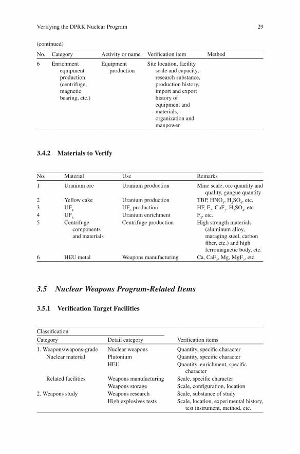
29Verifying the DPRK Nuclear Program
No. Category Activity or name Veri fi cation item Method
6 Enrichment equipment production (centrifuge, magnetic bearing, etc.)
Equipment production
Site location, facility scale and capacity, research substance, production history, import and export history of equipment and materials, organization and manpower
3.4.2 Materials to Verify
No. Material Use Remarks
1 Uranium ore Uranium production Mine scale, ore quantity and quality, gangue quantity
2 Yellow cake Uranium production TBP, HNO 3 , H
2 SO
4 , etc.
3 UF 4 UF
6 production HF, F
2 , CaF
2 , H
2 SO
4 , etc.
4 UF 6 Uranium enrichment F
2 , etc.
5 Centrifuge components and materials
Centrifuge production High strength materials (aluminum alloy, maraging steel, carbon fi ber, etc.) and high ferromagnetic body, etc.
6 HEU metal Weapons manufacturing Ca, CaF 2 , Mg, MgF
2 , etc.
3.5 Nuclear Weapons Program-Related Items
3.5.1 Veri fi cation Target Facilities
Classi fi cation
Veri fi cation items Category Detail category
1. Weapons/wapons-grade Nuclear weapons Quantity, speci fi c character Nuclear material Plutonium Quantity, speci fi c character
HEU Quantity, enrichment, speci fi c character
Related facilities Weapons manufacturing Scale, speci fi c character Weapons storage Scale, con fi guration, location
2. Weapons study Weapons research Scale, substance of study High explosives tests Scale, location, experimental history,
test instrument, method, etc.
(continued)
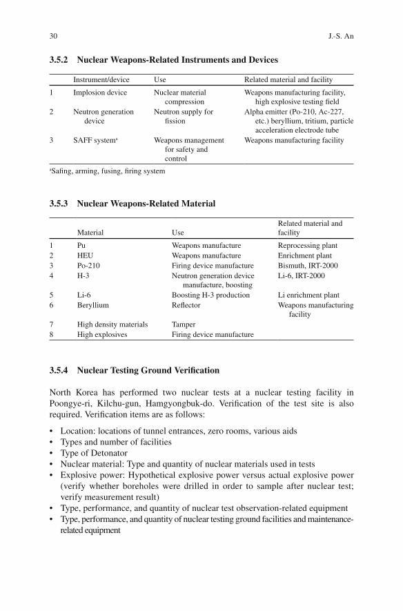
30 J.-S. An
3.5.2 Nuclear Weapons-Related Instruments and Devices
Instrument/device Use Related material and facility
1 Implosion device Nuclear material compression
Weapons manufacturing facility, high explosive testing fi eld
2 Neutron generation device
Neutron supply for fi ssion
Alpha emitter (Po-210, Ac-227, etc.) beryllium, tritium, particle acceleration electrode tube
3 SAFF system a Weapons management for safety and control
Weapons manufacturing facility
a Sa fi ng, arming, fusing, fi ring system
3.5.3 Nuclear Weapons-Related Material
Material Use Related material and facility
1 Pu Weapons manufacture Reprocessing plant 2 HEU Weapons manufacture Enrichment plant 3 Po-210 Firing device manufacture Bismuth, IRT-2000 4 H-3 Neutron generation device
manufacture, boosting Li-6, IRT-2000
5 Li-6 Boosting H-3 production Li enrichment plant 6 Beryllium Re fl ector Weapons manufacturing
facility 7 High density materials Tamper 8 High explosives Firing device manufacture
3.5.4 Nuclear Testing Ground Veri fi cation
North Korea has performed two nuclear tests at a nuclear testing facility in Poongye-ri, Kilchu-gun, Hamgyongbuk-do. Veri fi cation of the test site is also required. Veri fi cation items are as follows:
Location: locations of tunnel entrances, zero rooms, various aids • Types and number of facilities • Type of Detonator • Nuclear material: Type and quantity of nuclear materials used in tests • Explosive power: Hypothetical explosive power versus actual explosive power • (verify whether boreholes were drilled in order to sample after nuclear test; verify measurement result) Type, performance, and quantity of nuclear test observation-related equipment • Type, performance, and quantity of nuclear testing ground facilities and maintenance-• related equipment
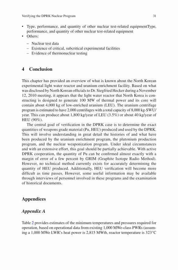
31Verifying the DPRK Nuclear Program
Type, performance, and quantity of other nuclear test-related equipmentType, • performance, and quantity of other nuclear test-related equipment Others:•
Nuclear test data – Existence of critical, subcritical experimental facilities – Evidence of thermonuclear testing –
4 Conclusion
This chapter has provided an overview of what is known about the North Korean experimental light water reactor and uranium enrichment facility. Based on what was disclosed by North Korean of fi cials to Dr. Siegfried Hecker during a November 12, 2010 meeting, it appears that the light water reactor that North Korea is con-structing is designed to generate 100 MW of thermal power and its core will contain about 4,000 kg of low-enriched uranium (LEU). The uranium centrifuge program is estimated to have 2,000 centrifuges with a total capacity of 8,000 kg-SWU/year. This can produce about 1,800 kg/year of LEU (3.5%) or about 40 kg/year of HEU (90%).
The central goal of veri fi cation in the DPRK case is to determine the exact quantities of weapons grade material (Pu, HEU) produced and used by the DPRK. This will involve understanding in great detail the histories of and what have been produced by the uranium enrichment program, the plutonium production program, and the nuclear weaponization program. Under ideal circumstances and with an extensive effort, this goal should be partially achievable. With active DPRK cooperation, the quantity of Pu can be con fi rmed almost exactly with a margin of error of a few percent by GRIM (Graphite Isotope Radio Method). However, no technical method currently exists for accurately determining the quantity of HEU produced. Additionally, HEU veri fi cation will become more dif fi cult as time passes. However, some useful information may be available through interviews of personnel involved in these programs and the examination of historical documents.
Appendices
Appendix A
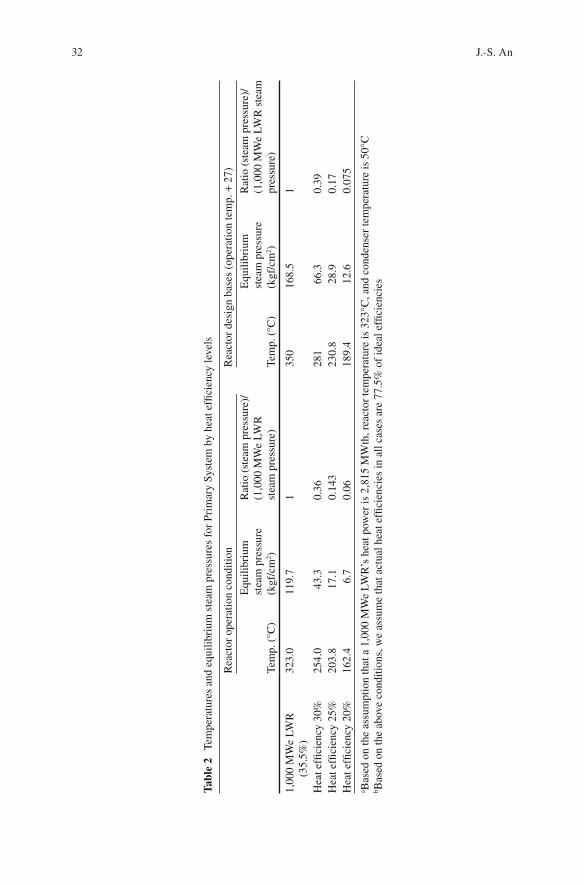
Table 2 provides estimates of the minimum temperatures and pressures required for operation, based on operational data from existing 1,000 MWe-class PWRs (assum-ing a 1,000 MWe LWR’s heat power is 2,815 MWth, reactor temperature is 323°C
32 J.-S. An
Tabl
e 2
Tem
pera
ture
s an
d eq
uilib
rium
ste
am p
ress
ures
for
Pri
mar
y Sy
stem
by
heat
ef fi
cien
cy le
vels
Rea
ctor
ope
ratio
n co
nditi
on
Rea
ctor
des
ign
base
s (o
pera
tion
tem
p. +
27)
Tem
p. (
°C)
Equ
ilibr
ium
st
eam
pre
ssur
e (k
gf/c
m 2 )
Rat
io (
stea
m p
ress
ure)
/(1
,000
MW
e LW
R
stea
m p
ress
ure)
Te
mp.
(°C
)
Equ
ilibr
ium
st
eam
pre
ssur
e (k
gf/c
m 2 )
Rat
io (
stea
m p
ress
ure)
/(1
,000
MW
e LW
R s
team
pr
essu
re)
1,00
0 M
We
LWR
(3
5.5%
) 32
3.0
119.
7 1
350
168.
5 1
Hea
t ef fi
cien
cy 3
0%
254.
0 43
.3
0.36
28
1 66
.3
0.39
H
eat e
f fi ci
ency
25%
20
3.8
17.1
0.
143
230.
8 28
.9
0.17
H
eat e
f fi ci
ency
20%
16
2.4
6.7
0.06
18
9.4
12.6
0.
075
a Bas
ed o
n th
e as
sum
ptio
n th
at a
1,0
00 M
We
LWR
’s h
eat p
ower
is 2
,815
MW
th, r
eact
or te
mpe
ratu
re is
323
°C, a
nd c
onde
nser
tem
pera
ture
is 5
0°C
b B
ased
on
the
abov
e co
nditi
ons,
we
assu
me
that
act
ual h
eat e
f fi ci
enci
es in
all
case
s ar
e 77
.5%
of
idea
l ef fi
cien
cies
33Verifying the DPRK Nuclear Program
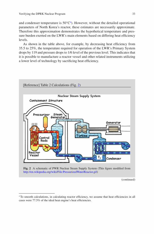
and condenser temperature is 50°C 4 ). However, without the detailed operational parameters of North Korea’s reactor, these estimates are necessarily approximate. Therefore this approximation demonstrates the hypothetical temperature and pres-sure burden exerted on the LWR’s main elements based on differing heat ef fi ciency levels.
As shown in the table above, for example, by decreasing heat ef fi ciency from 35.5 to 25%, the temperature required for operation of the LWR’s Primary System drops by 119 and pressure drops to 1/6 level of the previous level. This indicates that it is possible to manufacture a reactor vessel and other related instruments utilizing a lower level of technology by sacri fi cing heat ef fi ciency.
4 To smooth calculations, in calculating reactor efficiency, we assume that heat efficiencies in all cases were 77.5% of the ideal heat engine’s heat efficiencies.
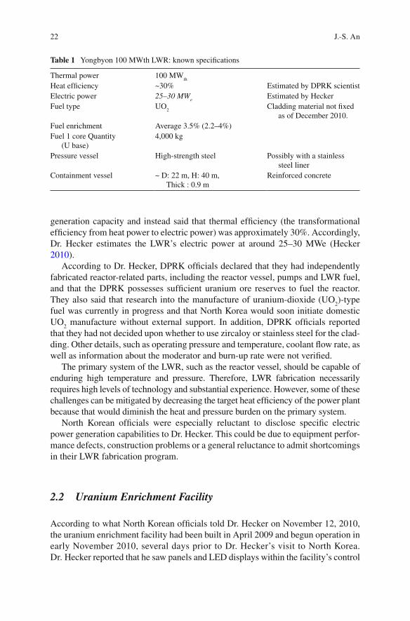
[Reference] Table 2 Calculations (Fig. 2 )
Fig. 2 A schematic of PWR Nuclear Steam Supply System (This fi gure modi fi ed from http://en.wikipedia.org/wiki/File:PressurizedWaterReactor.gif )
(continued)
34 J.-S. An
5 This is a hypothetical temperature. 6 In the absence of actual temperature information we substituted an arbitrary temperature. If temperature changes, heat efficiency would change, but the system and overall trends would not change significantly.
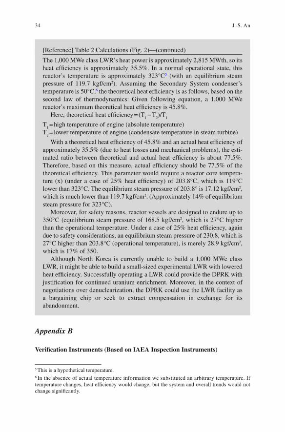
The 1,000 MWe class LWR’s heat power is approximately 2,815 MWth, so its heat ef fi ciency is approximately 35.5%. In a normal operational state, this reactor’s temperature is approximately 323°C 5 (with an equilibrium steam pressure of 119.7 kgf/cm 2 ). Assuming the Secondary System condenser’s temperature is 50°C, 6 the theoretical heat ef fi ciency is as follows, based on the second law of thermodynamics: Given following equation, a 1,000 MWe reactor’s maximum theoretical heat ef fi ciency is 45.8%.
Here, theoretical heat ef fi ciency = (T 1 − T
2 )/T
1
T 1 = high temperature of engine (absolute temperature)
T 2 = lower temperature of engine (condensate temperature in steam turbine)
With a theoretical heat ef fi ciency of 45.8% and an actual heat ef fi ciency of approximately 35.5% (due to heat losses and mechanical problems), the esti-mated ratio between theoretical and actual heat ef fi ciency is about 77.5%. Therefore, based on this measure, actual ef fi ciency should be 77.5% of the theoretical ef fi ciency. This parameter would require a reactor core tempera-ture (x) (under a case of 25% heat ef fi ciency) of 203.8°C, which is 119°C lower than 323°C. The equilibrium steam pressure of 203.8° is 17.12 kgf/cm 2 , which is much lower than 119.7 kgf/cm 2 . (Approximately 14% of equilibrium steam pressure for 323°C).
Moreover, for safety reasons, reactor vessels are designed to endure up to 350°C (equilibrium steam pressure of 168.5 kgf/cm 2 , which is 27°C higher than the operational temperature. Under a case of 25% heat ef fi ciency, again due to safety considerations, an equilibrium steam pressure of 230.8, which is 27°C higher than 203.8°C (operational temperature), is merely 28.9 kgf/cm 2 , which is 17% of 350.
Although North Korea is currently unable to build a 1,000 MWe class LWR, it might be able to build a small-sized experimental LWR with lowered heat ef fi ciency. Successfully operating a LWR could provide the DPRK with justi fi cation for continued uranium enrichment. Moreover, in the context of negotiations over denuclearization, the DPRK could use the LWR facility as a bargaining chip or seek to extract compensation in exchange for its abandonment.
[Reference] Table 2 Calculations (Fig. 2)—(continued)
Appendix B
Veri fi cation Instruments (Based on IAEA Inspection Instruments)
(1)
Ver
i fi ca
tion
Mea
sure
men
ts a
t Nat
ural
and
Low
Enr
iche
d U
rani
um C
onve
rsio
n an
d Fa
bric
atio
n Pl
ants
(IA
EA
, IA
EA
Saf
egua
rds
Man
ual
SMC
5 (2
003)
, p. 1
3)
Mat
eria
l C
ateg
ory
Mai
n st
ratu
m
Mat
eria
l typ
e co
mpo
nent
s D
efec
t ty
pe
Def
ect d
escr
iptio
n M
easu
rem
ents
req
uire
d A
pplic
able
m
etho
d R
ecom
men
ded
inst
rum
ents
In-d
irec
t-us
e Fr
esh
fuel
(as
sem
blie
s bu
ndle
s, r
ods)
(F
F, F
R)
DU
, NU
, LE
U
Gro
ss
Rep
lace
d by
dum
my,
or
mis
sing
Id
enti fi
catio
n, r
adia
tion
()
U r
adia
tion
(LE
U)
A (
1), H
M
MC
N, M
MC
C,
MM
CG
, HM
-5
LE
U
Part
ial
Low
er U
-235
C
onte
nt
U a
nd U
-235
Con
tent
F
UN
CL
+ H
M-5
(2),
FR
SC,
MM
CN
+ H
M-5
(2)
D
U, N
U, L
EU
B
ias
(4)
U c
onte
nt b
ias
U a
nd U
-235
con
tent
B
+ D
(3
) FR
SC
Sint
ered
pel
lets
(PL
),
gree
n pe
llets
, po
wde
r (P
D),
sc
rap
(SC
)
DU
, NU
, LE
U
Gro
ss
No
uran
ium
U
rad
iatio
n H
M
MC
N, M
MC
C,
MM
CG
, HM
-5 (
4)
Part
ial
Part
of
uran
ium
m
issi
ng
U a
nd U
-235
con
tent
B
+ F
E
BA
L +
MM
CN
LE
U
Bia
s U
con
tent
bia
s U
and
U-2
35 c
onte
nt
B +
D
EB
AL
+ D
A
UF 6 c
ylin
der
(VF)
(5)
L
EU
G
ross
N
o ur
aniu
m
Ura
nium
pre
senc
e H
A
cous
tic +
MM
CN
or
MM
CG
(6)
Pa
rtia
l L
ower
U-2
35
cont
ent
U a
nd U
-235
con
tent
B
+ F
L
CB
S +
MM
CG
+ U
LTG
, L
CB
S +
MM
CN
B
ias
U c
onte
nt b
ias
U a
nd U
-235
con
tent
B
+ D
L
CB
S +
DA
N
U
Gro
ss
No
uran
ium
U
rani
um p
rese
nce
H
Aco
ustic
+ M
MC
N o
r M
MC
G (
6)
Part
ial
Part
of
uran
ium
m
issi
ng
U c
onte
nt
B +
H (
7)
LC
BS
+ M
MC
N o
r M
MC
G
(con
tinue
d)
Mat
eria
l C
ateg
ory
Mai
n st
ratu
m
Mat
eria
l typ
e co
mpo
nent
s D
efec
t ty
pe
Def
ect d
escr
iptio
n M
easu
rem
ents
req
uire
d A
pplic
able
m
etho
d R
ecom
men
ded
inst
rum
ents
DU
G
ross
N
o ur
aniu
m
Ura
nium
pre
senc
e H
A
cous
tic +
MM
CN
or
MM
CG
(6)
W
aste
D
U, N
U, L
EU
G
ross
N
o ur
aniu
m
Rad
iatio
n (D
N)
U
radi
atio
n (L
EU
) H
M
MC
N, M
MC
C,
MM
CG
, HM
-5
Not
es:
(1)
Whe
re a
pplic
able
. (2
) H
M-5
use
d fo
r ac
tive
leng
th m
easu
rem
ent.
(3)
Pelle
t sam
plin
g at
rod
load
ing
stat
ion
(+E
BA
L).
A r
od s
cann
er m
ay b
e us
ed in
stea
d if
the
nucl
ear
mat
eria
l con
tent
in th
e ro
ds is
det
erm
ined
with
RSD
< 0
.06:
in
this
cas
e w
eigh
ing
is n
ot r
equi
red.
(4
) H
M-5
not
to b
e us
ed w
ith n
este
d (g
ross
+ p
artia
l + b
ias
defe
cts)
sam
plin
g pl
ans.
(5
) Fo
r U
F6 th
e op
erat
or’s
dec
lara
tion
of u
rani
um c
once
ntra
tion
is a
ccep
ted
if it
doe
s no
t dif
fer
by m
ore
than
0.0
03 f
rom
the
stoi
chio
met
ric
valu
e (0
.676
).
(6)
For
veri
fyin
g he
els
in U
F 6 cyl
inde
rs, w
eigh
ing
and
radi
atio
n m
easu
rem
ents
can
be
used
. (7
) E
nric
hmen
t mea
sure
men
ts f
or n
atur
al U
F 6 are
not
req
uire
d fo
r pa
rtia
l def
ects
.
(con
tinue
d)
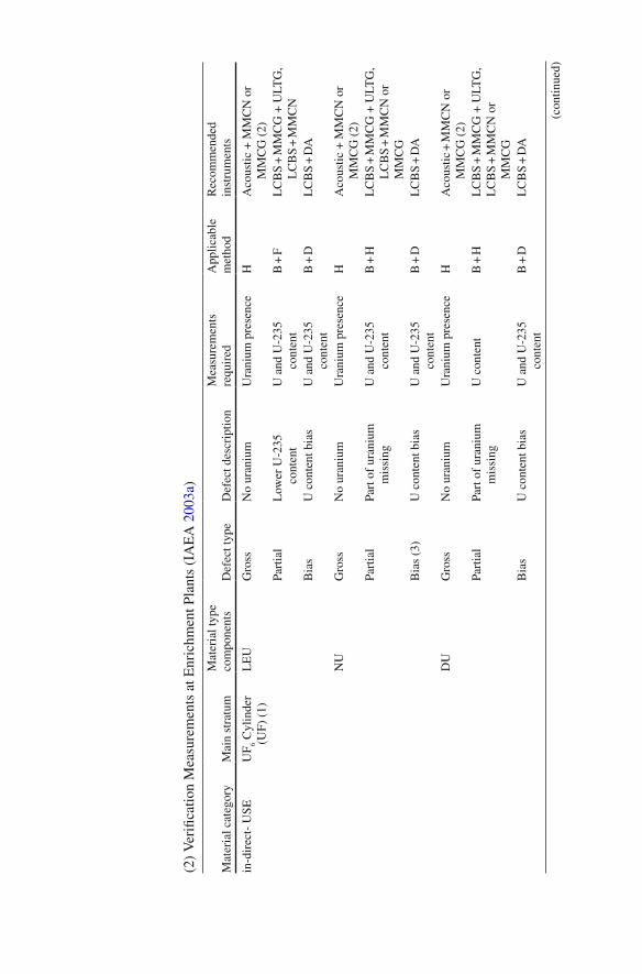
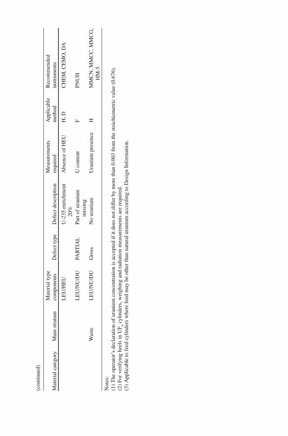
(2)
Ver
i fi ca
tion
Mea
sure
men
ts a
t Enr
ichm
ent P
lant
s (I
AE
A 2
003a
)
Mat
eria
l cat
egor
y M
ain
stra
tum
M
ater
ial t
ype
com
pone
nts
Def
ect t
ype
Def
ect d
escr
iptio
n M
easu
rem
ents
re
quir
ed
App
licab
le
met
hod
Rec
omm
ende
d in
stru
men
ts
in-d
irec
t- U
SE
UF 6 C
ylin
der
(UF)
(1)
L
EU
G
ross
N
o ur
aniu
m
Ura
nium
pre
senc
e H
A
cous
tic +
MM
CN
or
MM
CG
(2)
Pa
rtia
l L
ower
U-2
35
cont
ent
U a
nd U
-235
co
nten
t B
+ F
L
CB
S +
MM
CG
+ U
LTG
, L
CB
S +
MM
CN
B
ias
U c
onte
nt b
ias
U a
nd U
-235
co
nten
t B
+ D
L
CB
S +
DA
NU
G
ross
N
o ur
aniu
m
Ura
nium
pre
senc
e H
A
cous
tic +
MM
CN
or
MM
CG
(2)
Pa
rtia
l Pa
rt o
f ur
aniu
m
mis
sing
U
and
U-2
35
cont
ent
B +
H
LC
BS
+ M
MC
G +
ULT
G,
LC
BS
+ M
MC
N o
r M
MC
G
Bia
s (3
) U
con
tent
bia
s U
and
U-2
35
cont
ent
B +
D
LC
BS
+ D
A
DU
G
ross
N
o ur
aniu
m
Ura
nium
pre
senc
e H
A
cous
tic +
MM
CN
or
MM
CG
(2)
Pa
rtia
l Pa
rt o
f ur
aniu
m
mis
sing
U
con
tent
B
+ H
L
CB
S +
MM
CG
+ U
LTG
, L
CB
S +
MM
CN
or
MM
CG
B
ias
U c
onte
nt b
ias
U a
nd U
-235
co
nten
t B
+ D
L
CB
S +
DA
(con
tinue
d)
Mat
eria
l cat
egor
y M
ain
stra
tum
M
ater
ial t
ype
com
pone
nts
Def
ect t
ype
Def
ect d
escr
iptio
n M
easu
rem
ents
re
quir
ed
App
licab
le
met
hod
Rec
omm
ende
d in
stru
men
ts
LE
U/H
EU
U
-235
enr
ichm
ent
20%
A
bsen
ce o
f H
EU
H
, D
CH
EM
, CE
MO
, DA
LE
U/N
U/D
U
PAR
TIA
L
Part
of
uran
ium
m
issi
ng
U c
onte
nt
F PN
UH
Was
te
LE
U/N
U/D
U
Gro
ss
No
uran
ium
U
rani
um p
rese
nce
H
MM
CN
, MM
CC
, MM
CG
, H
M-5
Not
es:
(1)
The
ope
rato
r’s
decl
arat
ion
of u
rani
um c
once
ntra
tion
is a
ccep
ted
if it
doe
s no
t dif
fer
by m
ore
than
0.0
03 f
rom
the
stoi
chio
met
ric
valu
e (0
.676
).
(2)
For
veri
fyin
g he
els
in U
F 6 cyl
inde
rs, w
eigh
ing
and
radi
atio
n m
easu
rem
ents
are
req
uire
d.
(3)
App
licab
le to
fee
d cy
linde
rs w
here
fee
d m
ay b
e ot
her
than
nat
ural
ura
nium
acc
ordi
ng to
Des
ign
Info
rmat
ion.
(con
tinue
d)
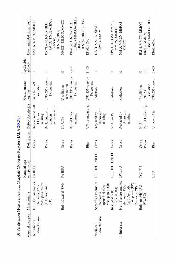
(3)
Ver
i fi ca
tion
Mea
sure
men
ts a
t Gra
phite
Mod
erat
e R
eact
or (
IAE
A 2
003b
)
Mat
eria
l cat
egor
y M
ain
stra
tum
M
ater
ial t
ype
com
pone
nts
Def
ect t
ype
Def
ect d
escr
iptio
n M
easu
rem
ents
re
quir
ed
App
licab
le
met
hods
R
ecom
men
ded
inst
rum
ents
Uni
rrad
iate
d di
rect
ed u
se
Fres
h fu
el a
ssem
bles
, el
emen
ts (
FM),
ro
ds, p
ins,
pla
tes
(FR
), c
oupo
ns
(CP)
Pu H
EU
G
ross
R
epla
cem
ent w
ith
LE
U, o
r m
issi
ng
Pu r
adia
tion/
U
radi
atio
n H
M
MC
N, N
MC
G, M
MC
C
Part
ial
Rod
, pin
, pla
te,
coup
on
repl
acem
ents
U/U
-235
con
tent
, Pu
con
tent
F
UN
CL
+ M
H-5
for
HE
U
AW
CC
, PN
CL
+ H
RG
S fo
r M
OX
, H
LN
C +
HR
GS
Bul
k M
ater
ial (
SM)
Pu H
EU
G
ross
N
o U
/Pu
U r
adia
tion
H
MM
CN
, MM
CG
, MM
CC
Pu
rad
iatio
n Pa
rtia
l Pa
rt o
f U
Pu
mis
sing
U
/U-2
35 c
onte
nt/
Pu c
onte
nt
B +
F
EB
AL
+ M
MC
N +
ULT
G,
EB
AL
+ M
MC
G +
HLT
G
(HE
U)
HL
NC
+ H
RG
S(M
OX
) B
ias
U/P
u co
nten
t bia
s U
/U-2
35 c
onte
nt/
Pu c
onte
nt
B +
D
EB
AL
+ D
A
Irra
diat
ed
dire
cted
use
Sp
ent f
uel a
ssem
bles
, el
emen
t (SF
) sp
ent f
uel r
ods,
pi
ns, p
late
s (S
R)
PU, H
EU
DN
LE
U
Gro
ss
Rep
lace
d by
du
mm
y, o
r m
issi
ng
Rad
iatio
n H
IC
VD
, MM
CN
, SFA
T,
CPM
U, H
SGM
Irra
diat
ed b
ulk
mat
eria
l (IM
) PU
, HE
U, D
NL
EU
G
ross
N
o U
, or
Pu
Rad
iatio
n H
C
PMU
, HSG
M, M
MC
G,
MM
CN
, MM
CC
In
dire
ct u
se
Fres
h fu
el a
ssem
bles
, el
emen
ts (
FE),
fr
esh
fuel
rod
s,
pins
, pla
tes
(FR
),
Cou
pons
(C
P)
DN
LE
U
Gro
ss
Rep
lace
d by
du
mm
y, o
r m
issi
ng
Rad
iatio
n H
M
H-5
, MM
CN
, MM
CG
, M
MC
C
Bul
k m
ater
ial (
SM,
WA
, SC
) D
NL
EU
G
ross
N
o U
U
rad
iatio
n H
H
M-4
, MM
CN
, MM
CC
Pa
rtia
l Pa
rt o
f U
mis
sing
U
/U-2
35
radi
atio
n B
+ F
E
BA
L +
MM
CN
, E
BA
L +
MM
CG
+ U
LTG
L
EU
B
ias
U c
onte
nt b
ias
U/U
-235
con
tent
B
+ D
E
BA
L +
DA
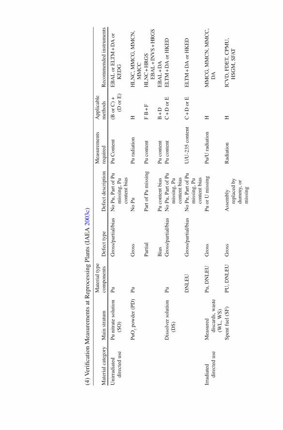
(4)
Ver
i fi ca
tion
Mea
sure
men
ts a
t Rep
roce
ssin
g Pl
ants
(IA
EA
200
3c )
Mat
eria
l cat
egor
y M
ain
stra
tum
M
ater
ial t
ype
com
pone
nts
Def
ect t
ype
Def
ect d
escr
iptio
n M
easu
rem
ents
re
quir
ed
App
licab
le
met
hods
R
ecom
men
ded
inst
rum
ents
Uni
rrad
iate
d di
rect
ed u
se
Pu n
itrat
e so
lutio
n (S
O)
Pu
Gro
ss/p
artia
l/bia
s N
o Pu
, Par
t of
Pu
mis
sing
, Pu
cont
ent b
ias
Pu C
onte
nt
(B o
r C
) +
(D
or
E)
EB
AL
or
ELT
M +
DA
or
KE
DG
PuO
2 pow
der
(PD
) Pu
G
ross
N
o Pu
Pu
rad
iatio
n H
H
LN
C, M
MC
G, M
MC
N,
MM
CC
Pa
rtia
l Pa
rt o
f Pu
mis
sing
Pu
con
tent
F
B +
F
HL
NC
+ H
RG
S E
BA
L +
INV
S +
HR
GS
Bia
s Pu
con
tent
bia
s Pu
con
tent
B
+ D
E
BA
L +
DA
D
isso
lver
sol
utio
n (D
S)
Pu
Gro
ss/p
artia
l/bia
s N
o Pu
, Par
t of
Pu
mis
sing
, Pu
cont
ent b
ias
Pu c
onte
nt
C +
D o
r E
E
LTM
+ D
A o
r H
KE
D
DN
LE
U
Gro
ss/p
artia
l/bia
s N
o Pu
, Par
t of
Pu
mis
sing
, Pu
cont
ent b
ias
U/U
-235
con
tent
C
+ D
or
E
ELT
M +
DA
or
HK
ED
Irra
diat
ed
dire
cted
use
M
easu
red
disc
ards
, was
te
(WL
, WS)
Pu, D
NL
EU
G
ross
Pu
or
U m
issi
ng
Pu/U
rad
iatio
n H
M
MC
G, M
MC
N, M
MC
C,
DA
Spen
t fue
l (SF
) PU
, DN
LE
U
Gro
ss
Ass
embl
y re
plac
ed b
y du
mm
y, o
r m
issi
ng
Rad
iatio
n H
IC
VD
, FD
ET,
CPM
U,
HSG
M, S
FAT
Mat
eria
l cat
egor
y M
ain
stra
tum
M
ater
ial t
ype
com
pone
nts
Def
ect t
ype
Def
ect d
escr
iptio
n M
easu
rem
ents
re
quir
ed
App
licab
le
met
hods
R
ecom
men
ded
inst
rum
ents
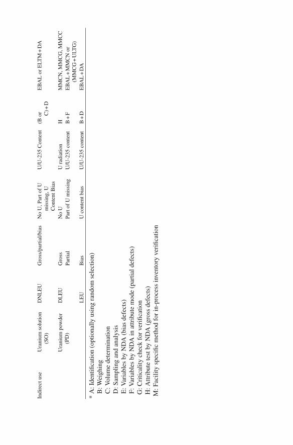
Indi
rect
use
U
rani
um s
olut
ion
(SO
) D
NL
EU
G
ross
/par
tial/b
ias
No
U, P
art o
f U
m
issi
ng, U
C
onte
nt B
ias
U/U
-235
Con
tent
(B
or C) +
D
EB
AL
or
ELT
M +
DA
Ura
nium
pow
der
(PD
) D
LE
U
Gro
ss
No
U
U r
adia
tion
H
MM
CN
, MM
CG
, MM
CC
Pa
rtia
l Pa
rt o
f U
mis
sing
U
/U-2
35 c
onte
nt
B +
F
EB
AL
+ M
MC
N o
r (M
MC
G +
ULT
G)
LE
U
Bia
s U
con
tent
bia
s U
/U-2
35 c
onte
nt
B +
D
EB
AL
+ D
A
* A
: Ide
nti fi
catio
n (o
ptio
nally
usi
ng r
ando
m s
elec
tion)
B: W
eigh
ing
C
: Vol
ume
dete
rmin
atio
n
D: S
ampl
ing
and
anal
ysis
E: V
aria
bles
by
ND
A (
bias
def
ects
)
F: V
aria
bles
by
ND
A in
attr
ibut
e m
ode
(par
tial d
efec
ts)
G
: Cri
tical
ity c
heck
for
ver
i fi ca
tion
H
: Attr
ibut
e te
st b
y N
DA
(gr
oss
defe
cts)
M
: Fac
ility
spe
ci fi c
met
hod
for
in-p
roce
ss in
vent
ory
veri
fi cat
ion
42 J.-S. An
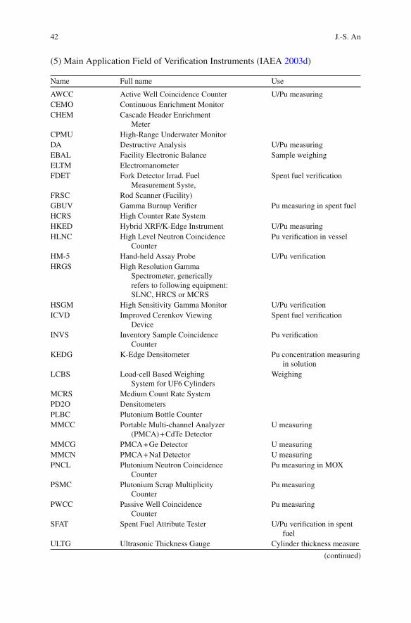
(5) Main Application Field of Veri fi cation Instruments (IAEA 2003d )
Name Full name Use
AWCC Active Well Coincidence Counter U/Pu measuring CEMO Continuous Enrichment Monitor CHEM Cascade Header Enrichment
Meter CPMU High-Range Underwater Monitor DA Destructive Analysis U/Pu measuring EBAL Facility Electronic Balance Sample weighing ELTM Electromanometer FDET Fork Detector Irrad. Fuel
Measurement Syste, Spent fuel veri fi cation
FRSC Rod Scanner (Facility) GBUV Gamma Burnup Veri fi er Pu measuring in spent fuel HCRS High Counter Rate System HKED Hybrid XRF/K-Edge Instrument U/Pu measuring HLNC High Level Neutron Coincidence
Counter Pu veri fi cation in vessel
HM-5 Hand-held Assay Probe U/Pu veri fi cation HRGS High Resolution Gamma
Spectrometer, generically refers to following equipment: SLNC, HRCS or MCRS
HSGM High Sensitivity Gamma Monitor U/Pu veri fi cation ICVD Improved Cerenkov Viewing
Device Spent fuel veri fi cation
INVS Inventory Sample Coincidence Counter
Pu veri fi cation
KEDG K-Edge Densitometer Pu concentration measuring in solution
LCBS Load-cell Based Weighing System for UF6 Cylinders
Weighing
MCRS Medium Count Rate System PD2O Densitometers PLBC Plutonium Bottle Counter MMCC Portable Multi-channel Analyzer
(PMCA) + CdTe Detector U measuring
MMCG PMCA + Ge Detector U measuring MMCN PMCA + NaI Detector U measuring PNCL Plutonium Neutron Coincidence
Counter Pu measuring in MOX
PSMC Plutonium Scrap Multiplicity Counter
Pu measuring
PWCC Passive Well Coincidence Counter
Pu measuring
SFAT Spent Fuel Attribute Tester U/Pu veri fi cation in spent fuel
ULTG Ultrasonic Thickness Gauge Cylinder thickness measure
(continued)
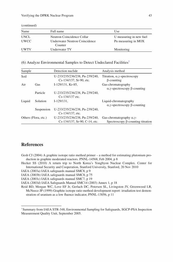
43Verifying the DPRK Nuclear Program
Name Full name Use
UNCL Neutron Coincidence Collar U measuring in new fuel UWCC Underwater Neutron Coincidence
Counter Pu measuring in MOX
UWTV Underwater TV Monitoring
(6) Analyze Environmental Samples to Detect Undeclared Facilities 7
Sample Detection nuclide Analysis method
Soil U-233/235/236/238, Pu-239/240, Cs-134/137, Sr-90, etc.
Titration, a , g -spectroscopy b -counting
Air Gas I-129/131, Kr-85, Gas-chromatography a , g -spectroscopy b -counting
Particle U-233/235/236/238, Pu-239/240, Cs-134/137 etc.
Liquid Solution I-129/131, Liquid-chromatography a , g -spectroscopy b -counting
Suspension U-233/235/236/238, Pu-239/240, Cs-134/137, etc.
Others (Flora, etc.) U-233/235/236/238, Pu-239/240, Cs-134/137, Sr-90, C-14, etc.
Gas-chromatography a , g -Spectroscopy b -counting titration
References
Gesh CJ (2004) A graphite isotope ratio method primer – a method for estimating plutonium pro-duction in graphite moderated reactors. PNNL-14568, Feb 2004, p 8
Hecker SS (2010) A return trip to North Korea’s Yongbyon Nuclear Complex. Center for International Security and Cooperation, Stanford University, Stanford, 20 Nov 2010
IAEA (2003a) IAEA safeguards manual SMC8, p 9 IAEA (2003b) IAEA safeguards manual SMC8, p 75 IAEA (2003c) IAEA safeguards manual SMC7, p 19 IAEA (2003d) IAEA Safeguards Manual SMC14 (2003) Annex 1, p 18 Reid BD, Morgan WC, Love EF Jr, Gerlach DC, Petersen SL, Livingston JV, Greenwood LR,
McNeece JP (1999) Graphite isotope ratio method development report: irradiation test demon-stration of uranium as a low fl uence indicator, PNNL-13056, p 11
(continued)
7 Summary from IAEA STR-348, Environmental Sampling for Safeguards, SGCP-PSA Inspection Measurement Quality Unit, September 2005.


![DPRK RFSA 24March[2]](https://img.pdfslide.net/doc/110x75/61fb5ba62e268c58cd5d39ac/dprk-rfsa-24march2.jpg)

